WO2013190816A1 - 洗濯機および洗濯機制御システム - Google Patents
洗濯機および洗濯機制御システム Download PDFInfo
- Publication number
- WO2013190816A1 WO2013190816A1 PCT/JP2013/003757 JP2013003757W WO2013190816A1 WO 2013190816 A1 WO2013190816 A1 WO 2013190816A1 JP 2013003757 W JP2013003757 W JP 2013003757W WO 2013190816 A1 WO2013190816 A1 WO 2013190816A1
- Authority
- WO
- WIPO (PCT)
- Prior art keywords
- washing machine
- unit
- display unit
- power
- course
- Prior art date
- Legal status (The legal status is an assumption and is not a legal conclusion. Google has not performed a legal analysis and makes no representation as to the accuracy of the status listed.)
- Ceased
Links
Images


Classifications
-
- D—TEXTILES; PAPER
- D06—TREATMENT OF TEXTILES OR THE LIKE; LAUNDERING; FLEXIBLE MATERIALS NOT OTHERWISE PROVIDED FOR
- D06F—LAUNDERING, DRYING, IRONING, PRESSING OR FOLDING TEXTILE ARTICLES
- D06F34/00—Details of control systems for washing machines, washer-dryers or laundry dryers
- D06F34/28—Arrangements for program selection, e.g. control panels therefor; Arrangements for indicating program parameters, e.g. the selected program or its progress
-
- G—PHYSICS
- G08—SIGNALLING
- G08C—TRANSMISSION SYSTEMS FOR MEASURED VALUES, CONTROL OR SIMILAR SIGNALS
- G08C17/00—Arrangements for transmitting signals characterised by the use of a wireless electrical link
- G08C17/02—Arrangements for transmitting signals characterised by the use of a wireless electrical link using a radio link
-
- D—TEXTILES; PAPER
- D06—TREATMENT OF TEXTILES OR THE LIKE; LAUNDERING; FLEXIBLE MATERIALS NOT OTHERWISE PROVIDED FOR
- D06F—LAUNDERING, DRYING, IRONING, PRESSING OR FOLDING TEXTILE ARTICLES
- D06F34/00—Details of control systems for washing machines, washer-dryers or laundry dryers
- D06F34/14—Arrangements for detecting or measuring specific parameters
-
- D—TEXTILES; PAPER
- D06—TREATMENT OF TEXTILES OR THE LIKE; LAUNDERING; FLEXIBLE MATERIALS NOT OTHERWISE PROVIDED FOR
- D06F—LAUNDERING, DRYING, IRONING, PRESSING OR FOLDING TEXTILE ARTICLES
- D06F39/00—Details of washing machines not specific to a single type of machines covered by groups D06F9/00 - D06F27/00
- D06F39/12—Casings; Tubs
-
- G—PHYSICS
- G08—SIGNALLING
- G08C—TRANSMISSION SYSTEMS FOR MEASURED VALUES, CONTROL OR SIMILAR SIGNALS
- G08C2201/00—Transmission systems of control signals via wireless link
- G08C2201/50—Receiving or transmitting feedback, e.g. replies, status updates, acknowledgements, from the controlled devices
Definitions
- the present invention relates to a washing machine for washing clothes put in a washing and dewatering tub, and a washing machine control system for controlling the washing machine.
- FIG. 9 is a cross-sectional view seen from the side showing the configuration of the conventional washing machine 101
- FIG. 10 is a circuit block diagram of the washing machine 101
- FIG. 11 shows the operation unit 102 of the washing machine 101. It is a figure which shows a structure.
- the washing machine 101 includes a housing 103 configured substantially in a rectangular parallelepiped shape. Inside the housing 103, a water receiving tank 104 configured in a substantially cylindrical shape is suspended by a suspension bar 105. In the water receiving tub 104, a washing and dewatering tub 106 having a substantially cylindrical shape is rotatably included. A stirring blade 107 is provided at the bottom of the washing and dewatering tank 106 so as to be rotatable about an axis along the vertical direction.
- a motor 108 for rotating the stirring blade 107 is provided on the outer bottom of the water receiving tank 104.
- the motor 108 is constituted by a direct current brushless motor.
- a power switching mechanism 109 is provided between the motor 108 and the stirring blade 107. The power switching mechanism 109 decelerates the driving force from the motor 108 during washing and transmits it to the stirring blade 107, and transmits the driving force from the motor 108 to the stirring blade 107 one-on-one during dehydration.
- a cover body 110 that constitutes a sprinkling part for watering is provided on the water receiving tank 104.
- a water supply valve 111 for supplying water into the washing and dewatering tub 106 is provided above the housing 103.
- a drain valve 112 for draining the washing water in the water receiving tank 104 is provided below the water receiving tank 104.
- a connecting portion 113 is provided at the lower part of the outer wall of the water receiving tank 104.
- a water level detector 114 that detects the water level of the water receiving tank 104 is connected to the connection unit 113.
- the water level detector 114 is configured to convert the water pressure at the connection portion 113 into an electrical frequency.
- an operation unit 102 is disposed on the front upper surface of the washing machine 101. Selection of a mode such as a driving course and various functions is performed by a user inputting to the input unit 126 of the operation unit 102.
- the control unit 122 provided inside the front upper surface of the washing machine 101 displays on the display unit 127 of the operation unit 102 based on the input information to notify the user.
- the motor 108 is driven by the inverter circuit 115.
- the inverter circuit 115 has six switching elements 116A to 116F. Each of the switching elements 116A to 116F has a parallel circuit composed of a power transistor and a reverse conducting diode.
- the power source 117 supplies a voltage to the inverter circuit 115 through a DC power source conversion device including a diode bridge 118, a choke coil 119, and a smoothing capacitor 120.
- the power source 117 also supplies a voltage to the pump 160, the water supply valve 111, the drain valve 112, and the power switching mechanism 109.
- the motor 108 is provided with three position detectors 121.
- the position detector 121 detects the rotational position of the motor 108.
- the control unit 122 has a rotation control unit 123.
- the rotation control unit 123 controls the drive circuit 124 based on the rotation position of the motor 108 detected by the position detector 121 and the water level of the water receiving tank 104 detected by the water level detector 114.
- the drive circuit 124 drives the inverter circuit 115 based on an instruction from the rotation control unit 123.
- the pump 160, the water supply valve 111, the drain valve 112, and the power switching mechanism 109 are connected to the load driving unit 125.
- the load driving unit 125 drives the pump 160, the water supply valve 111, the drain valve 112, and the power switching mechanism 109 based on an instruction from the control unit 122.
- the operation unit 102 includes an input unit 126 for inputting the washing time, the number of times of rinsing, and the dehydration time, and a display unit 127 for displaying the washing time, the number of times of rinsing, the dehydration time, and the like input to the input unit 126.
- an input unit 126 for inputting the washing time, the number of times of rinsing, and the dehydration time
- a display unit 127 for displaying the washing time, the number of times of rinsing, the dehydration time, and the like input to the input unit 126.
- the input unit 126 includes a washing time setting switch 126a for setting a washing time, a rinsing frequency setting switch 126b for setting a rinsing frequency, a dehydration time setting switch 126c for setting a dehydration time, and a drying time.
- a drying time setting switch 126d has a drying time setting switch 126d.
- the input unit 126 includes a start / pause switch 126e, a power-on switch 126f, a power-off switch 126g, and the like.
- the display unit 127 includes a washing time display unit 127a, a rinse count display unit 127b, a dehydration time display unit 127c, a drying time display unit 127d, and the like.
- the input unit 126 includes a driving course selection switch 126h that selects any one of a plurality of basic driving courses and special driving courses, and a plurality of driving courses corresponding to each of the plurality of basic driving courses and special driving courses. And a selection display portion 127e.
- the special operation course is set by changing at least one of the washing time, the number of times of rinsing, and the dehydrating time by input to the input unit 126.
- the plurality of driving course selection display units 127e are each configured by a light emitting diode.
- the basic driving course includes, for example, an “automatic course”, a “hurry course”, and a “home cleaning course”. “Omakase Course” is the most standard driving course. For example, the washing time is set to “9 minutes”, the number of times of rinsing is set to “twice water injection”, and the dehydration time is set to “7 minutes”. ing.
- the “hurry course” is a basic operation course for washing in a hurry.
- the washing time is set to “3 minutes”
- the number of rinsings is set to “1 water injection”
- the dehydration time is “3 minutes”. "Is set.
- the “house cleaning course” is a basic operation course for washing clothes recommended for dry cleaning with the washing machine 101 in the home.
- the washing time is set to “12 minutes” and the number of times of rinsing is “ “Twice” is set, and the dehydration time is set to “40 seconds”.
- the driving course selection display section 127e is provided for each of the “automatic course”, “hurry course”, “house cleaning course”, and “special driving course”. Every time the driving course selection switch 126h is pressed, the driving course selection display section 127e is switched in order of “automatic course”, “hurry course”, “home cleaning course”, and “special driving course”, and lights up.
- the washing time, the number of times of rinsing, and the dehydrating time specified in advance in the “automatic course” that is the most standard driving course are selected.
- the washing time display portion 127a, the rinse count display portion 127b, and the dehydration time display portion 127c are displayed on the washing time display portion 127a, the rinse count display portion 127b, and the dehydration time display portion 127c, respectively.
- the user then performs his / her own washing while referring to the washing time, the number of times of rinsing, and the dehydrating time of the “Omakase Course” displayed on the washing time display portion 127a, the rinse count display portion 127b, and the dehydration time display portion 127c.
- the washing time setting switch 126a the rinsing number setting switch 126b, and the dehydration time setting switch 126c is pressed a desired number of times.
- the user can set a special operation course by changing at least one of the washing time, the number of times of rinsing, and the dehydration time of the “Random Course”.
- control unit 122 performs a series of steps of washing, rinsing, and dehydration based on the conditions of the “special operation course” set by the input unit 126, and the drive circuit 124 and the load driving unit 125. To control.
- ⁇ Provides a washing machine with excellent operability and a washing machine control system that can set a washing machine operation course from a remote location.
- the washing machine performs wireless communication with the terminal device.
- the washing machine includes a control unit that controls the operation and communication of the washing machine, and an operation display unit that is arranged in the left-right direction above the washing machine and sets and displays an operation course.
- the operation display unit includes a power-on switch for turning on the power, a display unit for displaying setting details of the driving course, and a washing machine transmission / reception unit for communicating with the terminal device.
- the control unit receives the driving course information transmitted from the terminal device by the washing machine transmission / reception unit, and displays the driving course and controls the driving based on the driving course information.
- the power-on switch is disposed on either the left or right side of the operation display unit, and the washing machine transmission / reception unit is disposed on the left or right side of the operation display unit on the opposite side to the position where the power-on switch is disposed. ing.
- the washing machine control system includes a terminal device and a washing machine that performs wireless communication with the terminal device.
- the washing machine includes a control unit that controls the operation and communication of the washing machine, and an operation display unit that is arranged in the left-right direction above the washing machine and sets and displays an operation course.
- the operation display unit includes a power-on switch that turns on the power, a display unit that displays the setting content of the driving course, and a washing machine transmission / reception unit that communicates with the terminal device.
- the terminal device has a terminal transmission / reception unit that communicates with the washing machine.
- the control unit of the washing machine receives the driving course information transmitted from the terminal transmission / reception unit of the terminal device, and displays the driving course and controls driving based on the driving course information.
- the power-on switch is arranged on either the left or right side of the operation display unit, and the washing machine transmission / reception unit is arranged on the left or right side of the operation display unit on the side opposite to the position where the power-on switch is arranged.
- FIG. 1 is a perspective view showing the configuration of the washing machine control system according to the first embodiment of the present invention.
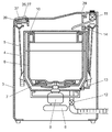
- FIG. 2 is a cross-sectional view of the washing machine of the washing machine control system according to the first embodiment of the present invention as seen from the side.
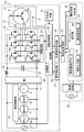
- FIG. 3 is a circuit block diagram of the washing machine control system according to the first embodiment of the present invention.
- FIG. 4 is a diagram showing an operation display unit of the washing machine in the washing machine control system according to the first embodiment of the present invention.
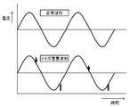
- FIG. 5 is a diagram showing a normal waveform of a power supply voltage and a noise superimposed waveform in the first embodiment of the present invention.
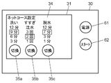
- FIG. 6A is a diagram illustrating a terminal operation unit of the terminal device of the washing machine control system according to the first embodiment of the present invention.
- FIG. 6B is a diagram illustrating a terminal operation unit for explaining a procedure of transferring the net course setting content of the terminal device of the washing machine control system according to the first embodiment of the present invention.
- FIG. 7 is a flowchart showing the operation of the washing machine control system in the embodiment of the present invention.
- FIG. 8 is a perspective view of a drum-type washing machine according to the second embodiment of the present invention.
- FIG. 9 is a cross-sectional view seen from the side showing the configuration of a conventional washing machine.
- FIG. 10 is a circuit block diagram of a conventional washing machine.
- FIG. 11 is a diagram illustrating a configuration of an operation unit of a conventional washing machine.
- FIG. 1 is a perspective view showing the configuration of the washing machine control system 50 according to the first embodiment of the present invention
- FIG. 2 is a sectional view of the washing machine 29 of the washing machine control system 50 as viewed from the side.
- FIG. 3 is a circuit block diagram of the washing machine control system 50.
- the washing machine 29 and the terminal device 28 are connected by wireless communication.
- the user can control the washing machine 29 while confirming the setting contents on the display unit 27 by operating the input unit 26 of the operation display unit 37 of the washing machine 29.
- the user can also operate the terminal device 28 to control the washing machine 29. Therefore, the terminal device 28 has a terminal transmission / reception unit 33 that exchanges information with the washing machine 29.
- the operation display unit 37 of the washing machine 29 includes a washing machine transmission / reception unit 38 that exchanges information with the terminal device 28.
- the washing machine 29 includes a housing 3 configured substantially in a rectangular parallelepiped.
- a water receiving tank 4 configured substantially in a cylindrical shape is suspended inside a housing 3 by a suspension bar 5.
- a washing and dewatering tub 6 having a substantially cylindrical shape is rotatably included in the water receiving tub 4, a washing and dewatering tub 6 having a substantially cylindrical shape is rotatably included in the water receiving tub 4, a washing and dewatering tub 6 having a substantially cylindrical shape is rotatably included.
- a stirring blade 7 is provided at the bottom of the washing and dewatering tub 6 so as to be rotatable about an axis along the vertical direction.
- a motor 8 for rotating the stirring blade 7 is provided on the outer bottom of the water receiving tank 4.
- the motor 8 is configured by a direct current brushless motor.
- a power switching mechanism 9 is provided between the motor 8 and the stirring blade 7. The power switching mechanism 9 decelerates the driving force from the motor 8 during washing and transmits it to the stirring blade 7, and transmits the driving force from the motor 8 to the stirring blade 7 one-on-one during dehydration.
- a cover body 10 that constitutes a sprinkling discharge section is provided on the water receiving tank 4.
- a water supply valve 11 for supplying water into the washing and dewatering tub 6 is provided above the housing 3.
- a drain valve 12 for draining the washing water in the water receiving tank 4 is provided below the water receiving tank 4.
- a connecting portion 13 is provided at the lower part of the outer wall of the water receiving tank 4.
- a water level detector 14 that detects the water level of the water receiving tank 4 is connected to the connecting portion 13.
- the water level detector 14 is configured to convert the water pressure at the connection portion 13 into an electrical frequency.
- the mode such as the driving course and various functions are selected when the user inputs to the input unit 26. Based on the input information, display is performed on the display unit 27 to notify the user.
- the operation display unit 37 is disposed on the front upper surface of the washing machine 29 and has a shape extending in the left-right direction.
- the operation display unit 37 is provided on an inclined surface on the front upper surface of the washing machine 29.
- a control unit 39 that controls the washing machine is disposed inside the front upper surface of the washing machine 29.
- the terminal transmission / reception part 33 protruded from the terminal device 28 was shown in FIG. 1, it is not limited to such a shape.
- the terminal transmission / reception unit 33 may be built in the terminal device 28.
- the inverter circuit 15 has six switching elements 16A to 16F. Each of the switching elements 16A to 16F has a parallel circuit composed of a power transistor and a reverse conducting diode.
- the power source 17 supplies a voltage to the inverter circuit 15 through a DC power source conversion device including a diode bridge 18, a choke coil 19, and a smoothing capacitor 20.
- the power source 17 also supplies voltage to the pump 60, the water supply valve 11, the drain valve 12, and the power switching mechanism 9.
- the motor 8 is provided with three position detectors 21.
- the position detector 21 detects the rotational position of the motor 8.
- the control unit 39 has a rotation control unit 23.
- the rotation control unit 23 controls the drive circuit 24 based on the rotation position of the motor 8 detected by the position detector 21 and the water level of the water receiving tank 4 detected by the water level detector 14.
- the drive circuit 24 drives the inverter circuit 15 based on an instruction from the rotation control unit 23.
- the pump 60, the water supply valve 11, the drain valve 12, and the power switching mechanism 9 are connected to the load driving unit 25.
- the load drive unit 25 drives the pump 60, the water supply valve 11, the drain valve 12, and the power switching mechanism 9 based on an instruction from the control unit 39.
- the operation display unit 37 includes an input unit 26 for inputting the washing time, the number of times of rinsing, and the dehydration time, and the display unit 27 for displaying the washing time, the number of times of rinsing, the dehydration time, and the like input to the input unit 26. have.
- the terminal device 28 includes a terminal operation unit 30.
- the terminal operation unit 30 includes a net course setting unit 31 and a transfer start button 32.
- the net course setting unit 31 sets the contents of the net course executed by the washing machine 29 by changing the contents of at least one of the series of washing, rinsing, and dehydration processes from the basic operation course.
- the terminal transmission / reception unit 33 transmits information representing the contents of the net course set by the net course setting unit 31 to the washing machine 29 by wireless communication.
- a wireless communication method NFC (which has been recently used in mobile phones and the like, which has a power supply for supplying voltage to the terminal operation unit 30 and the terminal transmission / reception unit 33 and supplies power using energy at the time of transmission.
- Communication can be performed by Near Field Communication), or a battery can be used as a power source.
- the net course setting unit 31 includes a terminal display unit 34 and a terminal input unit 35.
- the terminal display unit 34 displays the contents of the washing, rinsing, and dehydration processes set in the net course.
- the terminal input unit 35 allows the user to change the setting contents.
- the driving state determination unit 36 determines the driving state of the washing machine 29 based on the data received by the terminal transmission / reception unit 33.
- the terminal operation unit 30 is configured by a touch panel, and is formed to include a net course setting unit 31 and a transfer start button 32.
- a mobile phone can be used as the terminal device 28 . Details of the terminal operation unit 30 will be described later (see FIGS. 6A and 6B).
- the washing machine 29 includes a control unit 39.
- the control unit 39 has a storage unit 40.
- the storage unit 40 stores information indicating the contents of the net course received by the washing machine transmission / reception unit 38.
- the control unit 39 performs program control on a series of steps of washing, rinsing, and dehydration based on information indicating the contents of the net course received by the washing machine transmission / reception unit 38 and stored in the storage unit 40.
- FIG. 4 is a diagram showing the operation display unit 37 of the washing machine 29 of the washing machine control system 50 according to the first embodiment of the present invention.
- the input unit 26 of the operation display unit 37 has a washing time setting switch 26a for setting a washing time, a rinse number setting switch 26b for setting the number of rinses, and a dehydration time setting switch 26c for setting the dehydration time. is doing.
- the input unit 26 includes a drying time setting switch 26d for setting a drying time, a start / pause switch 26e, a power-on switch 26f, a power-off switch 26g, and the like, and an existing course selection switch 26i. .
- the existing course selection switch 26i can select one of the courses that the washing machine 29 has in advance.
- An operation start can be instructed by the start / pause switch 26e.
- the washing machine 29 can be turned on and off by the power-on switch 26f and the power-off switch 26g.
- At least one of the washing time, the number of times of rinsing, and the dehydration time of the course selected by the existing course selection switch 26i is set as at least one of the washing time setting switch 26a, the number of times of rinsing setting switch 26b, and the dehydration time setting switch 26c.
- the display unit 27 includes a washing time display unit 27 a, a rinse count display unit 27 b, a dehydration time display unit 27 c, a drying time display unit 27 d, and the like, and a net that is turned on when a net course is selected by the terminal device 28.
- a course display portion 27f is provided.
- the display unit 27 includes a plurality of driving course selection display units 27e corresponding to the plurality of basic driving courses and the special driving course, respectively.
- the special operation course is set by changing at least one of the washing time, the number of times of rinsing, and the dehydrating time by the input to the input unit 26.
- the plurality of driving course selection display units 27e are each configured by a light emitting diode.
- the basic driving course includes, for example, an “automatic course”, a “hurry course”, and a “home cleaning course”. “Omakase Course” is the most standard driving course. For example, the washing time is set to “9 minutes”, the number of times of rinsing is set to “twice water injection”, and the dehydration time is set to “7 minutes”. ing.
- the “hurry course” is a basic operation course for washing in a hurry.
- the washing time is set to “3 minutes”
- the number of rinsings is set to “1 water injection”
- the dehydration time is “3 minutes”. "Is set.
- the “house cleaning course” is a basic operation course for washing clothes recommended for dry cleaning with the washing machine 29 in the home.
- the washing time is set to “12 minutes” and the number of times of rinsing is “ “Twice” is set, and the dehydration time is set to “40 seconds”.
- the driving course selection display unit 27e is provided for each of the “automatic course”, “hurry course”, “house cleaning course”, and “special driving course”.
- the operation display unit 37 further includes a washing machine transmission / reception unit 38, and the terminal device 28 is set by the user approaching the washing machine transmission / reception unit 38 by setting the terminal device 28 set by inputting the contents of the net course.
- Information is transmitted by the terminal transmission / reception unit 33 provided in, and input to the washing machine 29.
- the washing machine transmission / reception unit 38 is disposed on the left side that is the opposite side of the power-on switch 26f provided on the right side with respect to the horizontal center of the operation display unit 37.
- the washing machine transmission / reception unit 38 in the operation display unit 37 is arranged on the left side of the center.
- the power-on switch 26f is connected to a power supply line (for example, a commercial power supply with a power supply voltage of 100 V).
- a noise component is superimposed on the power supply voltage.
- FIG. 5 is a diagram showing a normal waveform of the power supply voltage and a noise superimposed waveform in the first embodiment of the present invention.
- a switch for turning on / off the power such as the power-on switch 26f, is often arranged on the right side so that it can be easily operated with the right hand, which is the dominant hand of many users. Switches that require action are preferentially placed on the right.
- the user's dominant hand is a right hand and a mobile phone is used as the terminal device 28.
- the user performs the setting operation on the washing machine 29 side with the right hand that is the dominant hand while holding the mobile phone with the left hand opposite to the dominant hand.
- the user When transmitting the operating conditions set in the terminal device 28 to the washing machine transmission / reception unit 38 of the washing machine 29, the user performs an operation of bringing the terminal device 28 close to the vicinity of the washing machine transmission / reception unit 38.
- the user's hand performing this action is the left hand.
- the user-friendly configuration can be realized by disposing the washing machine transmitting / receiving unit 38 on the left side of the center.
- the width of the washing machine 29 is about 640 mm, but is generally formed between about 520 mm and 640 mm.
- the power-on switch 26f is arranged on either the left or right side of the operation display unit 37, and the washing machine transmission / reception unit 38 is on the side opposite to the arrangement position of the power-on switch 26f. It is arranged on either the left or right side.
- the position of the washing machine transmitting / receiving unit 38 can be separated from the power-on switch 26f by 200 mm or more. It can be secured sufficiently.
- the terminal transmission / reception part 33 provided in the terminal device 28 and the washing machine transmission / reception part 38 provided in the washing machine 29 can transmit / receive information using NFC, for example.
- FIG. 6A is a diagram illustrating the terminal operation unit 30 of the terminal device 28 of the washing machine control system 50 according to the first embodiment of the present invention
- FIG. 6B transfers the net course setting content of the terminal device 28. It is a figure which shows the terminal operation part 30 explaining a procedure.
- the user presses the power button 61 of the terminal operation unit 30 of the terminal device 28 and then presses the switching buttons 35a to 35c of the terminal input unit 35 in the net course setting unit 31.
- the washing time of the net course, the number of rinses, and the dehydration time can be set.
- the user can check the setting contents on the terminal display unit 34.
- the user can transmit the setting contents to the washing machine 29 by pressing the transfer start button 32 after the setting is completed.
- the function of the transfer start button 32 will be described later with reference to the flowchart of FIG.
- the terminal device 28 can perform the above-described operation by starting and functioning a dedicated application.
- washing machine control system 50 configured as described above will be described below.
- FIG. 7 is a flowchart showing the operation of the washing machine control system 50 in the embodiment of the present invention.
- Step S43 shows a case where the washing time is changed.
- FIG. 6A shows an example in which the washing time “6 minutes” is changed to the washing time “9 minutes” by the user touching the switching button 35 a of the touch panel as the terminal input unit 35.
- Step S44 shows a case where the number of times of rinsing is changed.
- FIG. 6A shows an example in which the number of times of rinsing “1” is changed to the number of times of rinsing “2” by the user touching the switching button 35 b of the touch panel as the terminal input unit 35.
- Step S45 shows a case where the dehydration time is changed.
- FIG. 6A shows an example in which the dehydration time “3 minutes” is changed to the dehydration time “7 minutes” by the user touching the switching button 35 c of the touch panel as the terminal input unit 35.
- the power of the washing machine 29 is in the “off” state (S46). Since the power is turned off, the washing machine 29 is not ready to receive information (receivable state). Therefore, the transfer start button 32 is not displayed as shown in FIG. 6A.
- the washing machine 29 When the user presses the power-on switch 26f of the washing machine 29, the washing machine 29 is turned on (S47).
- the washing machine 29 transmits power-on data (data notifying that the power has been turned on) to the terminal device 28 through the washing machine transmission / reception unit 38 (S48).
- the terminal device 28 receives the power-on data, and recognizes that the washing machine 29 is turned on by the driving state determination unit 36 (S49). The terminal device 28 recognizes that the washing machine 29 is ready to receive. As a result, the terminal device 28 displays the transfer start button 32 on the terminal operation unit 30 as shown in FIG. 6B (S50).
- the washing machine 29 receives all data of the net course setting by the washing machine transmission / reception unit 38 (S54).
- the washing machine 29 stores all data of the net course setting in the storage unit 40 (S55) and lights the net course display unit 27f of the operation display unit 37 (S56).
- S55 the storage unit 40
- S56 the washing machine 29 stores all data of the net course setting in the storage unit 40
- all data can be stored even when the power of the washing machine 29 is shut off.
- the washing machine 29 starts a sequence operation based on the received net course setting content (S57). Note that the washing machine 29 can also drive a sequence based on the received net course setting contents by pressing a start button 62 provided on the terminal operation unit 30 of the terminal device 28.
- FIG. 8 is a perspective view of a drum-type washing machine 129 according to the second embodiment of the present invention. Note that in this embodiment, the same components as those described in the first embodiment are denoted by the same reference numerals, and description thereof is omitted.
- the washing machine 129 and the terminal device 28 are connected by wireless communication as in the first embodiment.
- the user can control the washing machine 129 while operating the input unit 26 of the operation display unit 37 of the washing machine 129 and confirming the setting contents on the display unit 27. Further, the washing machine 129 can be controlled by operating the terminal device 28. Therefore, the terminal device 28 is provided with a terminal transmission / reception unit 33 for exchanging information with the washing machine 129, and the operation display unit 37 of the washing machine 129 has a washing machine transmission / reception unit 38 for exchanging information with the terminal device 28. Is provided.
- the operation display unit 37 has a shape extending in the left-right direction on the front upper surface of the washing machine 129.
- the operation display unit 37 is provided on an inclined surface on the front upper surface of the washing machine 129.
- a control unit 39 for controlling the washing machine is disposed inside the front upper surface of the washing machine 129.
- the operation display unit 37, the operation unit, the washing machine transmission / reception unit 38, and the like for example, the arrangement shown in FIG. 4 can be used.
- washing machine 129 Since the specific operation of the washing machine 129 is the same as that of the washing machine 29 of the first embodiment, detailed description thereof is omitted.
- washing machine transmission / reception unit 38 is disposed on the left side opposite to the power-on switch 26f provided on the right side with respect to the center in the lateral direction of the operation display unit 37.
- washing machine transmission / reception unit 38 in the operation display unit 37 will be described. Similar to the first embodiment, as shown in the lower side of FIG. 5, there may be a case where a large amount of noise components are superimposed on the power supply voltage. It is also assumed that it is affected by the magnetic field due to the main current flowing.
- the power-on switch 26f is arranged on either the left or right side of the operation display unit 37, and the washing machine transmission / reception unit 38 is provided. It is arranged on the left or right side of the operation display section 37 on the opposite side to the arrangement position of the power-on switch 26f.
- the position of the washing machine transmission / reception unit 38 can be sufficiently separated from the power-on switch 26f, so that the distance from the communication switch 26f is less susceptible to noise generated around the power-on switch 26f. It can be secured sufficiently.
- a switch for turning on / off the power such as the power-on switch 26f, is arranged on the right side so that the right hand, which is the dominant hand of many users, is easy to operate.
- the switch that requires quick action is preferentially arranged on the right side.
- the user's dominant hand is the right hand and a mobile phone is used as the terminal device 28.
- the user operates the setting operation on the washing machine 29 side with the right hand which is the dominant hand while holding the mobile phone with the left hand opposite to the dominant hand.
- the user performs an operation of bringing the terminal device 28 close to the vicinity of the washing machine transmission / reception unit 38 when transmitting the operation condition set by the terminal device 28 to the washing machine transmission / reception unit 38 of the washing machine 129.
- the user's hand performing this approach is the left hand.
- the user-friendly configuration can be realized by arranging the washing machine transmitting / receiving unit 38 on the left side of the center.
- the washing machine transmission / reception unit 38 of the washing machines 29 and 129 is arranged on the left side of the center of the operation display unit 37, and the power-on switch 26 f is arranged on the right side of the operation display unit 37.
- washing machine transmission / reception unit 38 on the inclined surface of the operation display unit 37, it is possible to prevent water from adhering to the washing machine transmission / reception unit 38. For this reason, water does not adhere to the terminal device 28 that is close to the washing machine transmitting / receiving unit 38 at the time of transmission, and communication failure can be prevented.
- washing machine control system 50 which communicates the terminal device 28 close to the washing machine transmission / reception part 38 of the washing machines 29 and 129 was demonstrated, this invention is not limited to this example.
- it may be configured to be connected by a short-range wireless communication technology using infrared rays or radio waves.
- the control system in the case where the washing machines 29 and 129 are used has been described.
- the apparatus controlled by the program is not limited to the washing machines 29 and 129. Any device that is program-controlled using a microcomputer can be applied to other devices, and the same operations and effects as those using the washing machines 29 and 129 can be obtained.
- the operability for the user can be improved and the transmission / reception function can be provided without being affected by electromagnetic noise. It is possible to realize an easy-to-use configuration that operates reliably and does not cause malfunction.
- washing machines 29 and 129 described in the embodiments are the washing machines 29 and 129 that perform wireless communication with the terminal device 28.
- the washing machines 29 and 129 include a control unit 39 that controls the operation and communication of the washing machines 29 and 129, and an operation display unit that is disposed in the left and right directions above the washing machines 29 and 129 and sets and displays an operation course. 37.
- the operation display unit 37 includes a power-on switch 26 f that turns on the power, a display unit 27 that displays the setting contents of the driving course, and a washing machine transmission / reception unit 38 that communicates with the terminal device 28.
- the control unit 39 receives the driving course information transmitted from the terminal device 28 by the washing machine transmission / reception unit 38, and performs driving course display and driving control based on the driving course information.
- the power-on switch 26f is arranged on either the left or right side of the operation display unit 37, and the washing machine transmission / reception unit 38 is either on the left or right side of the operation display unit 37 on the opposite side to the position where the power-on switch 26f is arranged. Arranged on the other side.
- the washing machine control system 50 in each embodiment includes a terminal device 28 and washing machines 29 and 129 that perform wireless communication with the terminal device 28.
- the washing machines 29 and 129 include a control unit 39 that controls the operation and communication of the washing machines 29 and 129, and an operation display unit that is disposed in the left and right directions above the washing machines 29 and 129 and sets and displays an operation course.
- the operation display unit 37 includes a power-on switch 26 f that turns on the power, a display unit 27 that displays the setting contents of the driving course, and a washing machine transmission / reception unit 38 that communicates with the terminal device 28.
- the terminal device 28 includes a terminal transmission / reception unit 33 that communicates with the washing machines 29 and 129.
- the control unit 39 of the washing machines 29 and 129 receives the driving course information transmitted from the terminal transmission / reception unit 33 of the terminal device 28 by the washing machine transmission / reception unit 38, and displays the driving course information and the driving course information based on the driving course information. Control the operation.
- the power-on switch 26f is arranged on either the left or right side of the operation display unit 37, and the washing machine transmission / reception unit 38 is either the left or right side of the operation display unit 37 on the side opposite to the position where the power-on switch 26f is arranged. Arranged on the side.
- the washing machine transmission / reception unit 38 can be operated by electromagnetic noise or the like by separating the washing machine transmission / reception unit 38 from the power-on switch 26f that is easy to operate and easily generate electromagnetic noise. It is possible to reliably transmit and receive a signal transmitted without being affected by the above.
- washing machine transmission / reception unit 38 is arranged on the left side of the center of the operation display unit 37, and the power-on switch 26f is arranged on the right side of the center of the operation display unit 37.
- Such a configuration makes it possible to realize a configuration that is easy to operate for a user whose right hand is the dominant hand.
- washing machine transmission / reception unit 38 is disposed on an inclined surface of the operation display unit 37.
- the present invention is useful as a washing machine for washing clothes put in the washing and dewatering tub, a washing machine control system for controlling the washing machine, and the like. Further, the present invention can also be applied to control of other electric devices that are electronically controlled.
Landscapes
- Engineering & Computer Science (AREA)
- Computer Networks & Wireless Communication (AREA)
- Physics & Mathematics (AREA)
- General Physics & Mathematics (AREA)
- Textile Engineering (AREA)
- Control Of Washing Machine And Dryer (AREA)
- Main Body Construction Of Washing Machines And Laundry Dryers (AREA)
- Detail Structures Of Washing Machines And Dryers (AREA)
- Selective Calling Equipment (AREA)
Abstract
端末装置(28)と無線通信を行う洗濯機(29)であって、洗濯機(29)の運転および通信の制御を行う制御部と、洗濯機(29)の上部に左右方向に配置され、運転コースの設定および表示を行う操作表示部(37)とを備えている。操作表示部(37)は、電源を投入する電源入りスイッチと、運転コースの設定内容を表示する表示部(26)と、端末装置(28)と通信を行う洗濯機送受信部(38)とを有している。制御部は、端末装置(28)から送信された運転コースの情報を洗濯機送受信部(38)で受信し、運転コースの情報に基づいて、運転コースの表示および運転の制御を行う。電源入りスイッチは、操作表示部(37)の左右いずれか一方側に配置され、洗濯機送受信部(38)は、電源入りスイッチの配置された位置とは反対側の、操作表示部(37)の左右いずれか他方側に配置されている。
Description
本発明は、洗濯兼脱水槽内に投入された衣類を洗濯する洗濯機、およびその洗濯機を制御する洗濯機制御システムに関する。
従来から、洗濯兼脱水槽内に投入された衣類を洗濯する洗濯機の制御方式として、制御部により、洗い、すすぎ、および脱水等の一連の工程をプログラム制御する方式が提案されている(例えば、特許文献1を参照)。
図9は、従来の洗濯機101の構成を示す横から見た断面図であり、図10は、同洗濯機101の回路ブロック図であり、図11は、同洗濯機101の操作部102の構成を示す図である。
図9において、洗濯機101は、実質的に直方体に構成された筐体103を備えている。筐体103の内部には、実質的に円筒形に構成された水受け槽104が、吊り棒105によって吊り下げられている。水受け槽104内には、実質的に円筒形に構成された洗濯兼脱水槽106が回転自在に内包されている。洗濯兼脱水槽106の底部には、撹拌翼107が、垂直方向に沿った軸の回りに回転自在に設けられている。
水受け槽104の外底部には、撹拌翼107を回転するモータ108が設けられている。モータ108は、直流ブラシレスモータにより構成されている。モータ108と撹拌翼107との間には、動力切換機構109が設けられている。動力切換機構109は、洗濯時にはモータ108からの駆動力を減速して撹拌翼107に伝達し、脱水時にはモータ108からの駆動力を一対一に撹拌翼107に伝達する。
水受け槽104の上には、散水用の吐出部を構成するカバー体110が設けられている。また、筐体103の上方には、洗濯兼脱水槽106内に給水する給水弁111が設けられている。さらに、水受け槽104の下方には、水受け槽104内の洗濯水を排水する排水弁112が設けられている。
水受け槽104の外壁下部には、接続部113が設けられている。接続部113には、水受け槽104の水位を検知する水位検知器114が接続されている。水位検知器114は、接続部113における水圧を電気的な周波数に変換するように構成されている。
また、洗濯機101の前方上面には、操作部102が配設されている。運転コース等のモードや各種機能の選択は、使用者が操作部102の入力部126に入力することによって行われる。洗濯機101の前方上面内方に設けられた制御部122は、入力された情報に基づいて、操作部102の表示部127に表示を行って、使用者に知らせる。
図10に示したように、モータ108は、インバータ回路115によって駆動される。インバータ回路115は、六個のスイッチング素子116A~116Fを有している。スイッチング素子116A~116Fは、それぞれ、パワートランジスタと逆導通ダイオードとによって構成される並列回路を有している。
電源117は、ダイオードブリッジ118、チョークコイル119、および平滑用コンデンサ120によって構成される直流電源変換装置を介して、インバータ回路115に電圧を供給する。電源117はまた、ポンプ160、給水弁111、排水弁112、および、動力切換機構109にも電圧を供給する。
モータ108には、三個の位置検出器121が設けられている。位置検出器121は、モータ108の回転位置を検出する。
制御部122は、回転制御部123を有している。回転制御部123は、位置検出器121によって検出されたモータ108の回転位置と、水位検知器114によって検知された水受け槽104の水位とに基づいて、駆動回路124を制御する。駆動回路124は、回転制御部123からの指示に基づいて、インバータ回路115を駆動する。
ポンプ160、給水弁111、排水弁112、および動力切換機構109は、負荷駆動部125に接続されている。負荷駆動部125は、制御部122からの指示に基づいて、ポンプ160、給水弁111、排水弁112、および動力切換機構109を駆動する。
操作部102は、洗い時間、すすぎ回数、および脱水時間等が入力される入力部126と、入力部126に入力された、洗い時間、すすぎ回数、および脱水時間等を表示する表示部127とを有している。
図11に示したように、入力部126は、洗い時間を設定する洗い時間設定スイッチ126a、すすぎ回数を設定するすすぎ回数設定スイッチ126b、脱水時間を設定する脱水時間設定スイッチ126c、および、乾燥時間を設定する乾燥時間設定スイッチ126dを有している。また、入力部126は、スタート・一時停止スイッチ126e、電源入りスイッチ126f、および電源切りスイッチ126g等を有している。
表示部127は、洗い時間表示部127a、すすぎ回数表示部127b、脱水時間表示部127c、および乾燥時間表示部127d等を有している。
また、入力部126は、複数の基本運転コース、および特別運転コースのいずれかを選択する運転コース選択スイッチ126hと、複数の基本運転コース、および特別運転コースのそれぞれに対応する、複数の運転コース選択表示部127eとを有している。ここで、特別運転コースは、入力部126への入力によって、洗い時間、すすぎ回数、および脱水時間の少なくとも一つが変更されることにより設定される。
複数の運転コース選択表示部127eは、それぞれ、発光ダイオードによって構成されている。基本運転コースには、例えば、「おまかせコース」、「お急ぎコース」、および「おうちクリーニングコース」が含まれている。「おまかせコース」は、最も標準的な運転コースであって、例えば洗い時間は「9分」に設定され、すすぎ回数は「注水2回」に設定され、脱水時間は「7分」に設定されている。
「お急ぎコース」は、急いで洗濯するための基本運転コースであって、例えば洗い時間は「3分」に設定され、すすぎ回数は「注水1回」に設定され、脱水時間は「3分」に設定されている。
「おうちクリーニングコース」は、ドライクリーニングを推奨されている衣類を家庭内の洗濯機101で洗うための基本運転コースであって、例えば洗い時間は「12分」に設定され、すすぎ回数は「ため2回」に設定され、脱水時間は「40秒」に設定されている。
特別運転コースにおいては、洗い時間、すすぎ回数、および脱水時間を、使用者が任意に設定することができる。運転コース選択表示部127eは、「おまかせコース」、「お急ぎコース」、「おうちクリーニングコース」および「特別運転コース」毎に設けられている。運転コース選択スイッチ126hを押すたびに、「おまかせコース」、「お急ぎコース」、「おうちクリーニングコース」、「特別運転コース」と、順番に運転コース選択表示部127eが切り替わって点灯してゆく。
次に、このような構成の洗濯機101において、その動作を説明する。
使用者が運転コース選択スイッチ126hを押すことによって、「特別運転コース」が選択されると、最も標準的な運転コースである「おまかせコース」に予め規定された洗い時間、すすぎ回数、および脱水時間が、洗い時間表示部127a、すすぎ回数表示部127b、および脱水時間表示部127cにそれぞれ表示される。そして、使用者は、洗い時間表示部127a、すすぎ回数表示部127b、および脱水時間表示部127cに表示された「おまかせコース」の洗い時間、すすぎ回数、および脱水時間を参照しながら、自らの洗濯事情に合わせて、洗い時間設定スイッチ126a、すすぎ回数設定スイッチ126b、および脱水時間設定スイッチ126cの少なくとも一つを所望の回数押す。これによって、使用者は、「おまかせコース」の洗い時間、すすぎ回数、および脱水時間の少なくとも一つを変更して、特別運転コースを設定することができる。
その後、制御部122は、入力部126によって設定された「特別運転コース」の条件に基づいて、洗い、すすぎ、および脱水の一連の工程を実行するように、駆動回路124と負荷駆動部125とを制御する。
一般に、洗濯機101が置かれている環境は照明が十分でない場合が多いので、この環境で操作を行うこと、例えば「特別運転コース」を設定するために「おまかせコース」の細かい設定を変更することは、使用者にとって楽な動作ではない。特に、高齢者には、操作が非常にやりづらく感じられるという課題がある。
離れた場所からでも洗濯機の運転コース等を設定できる、操作性に優れた洗濯機および洗濯機制御システムが提供される。
洗濯機は、端末装置と無線通信を行う。洗濯機は、洗濯機の運転および通信の制御を行う制御部と、洗濯機の上部に左右方向に配置され、運転コースの設定および表示を行う操作表示部とを備えている。また、操作表示部は、電源を投入する電源入りスイッチと、運転コースの設定内容を表示する表示部と、端末装置と通信を行う洗濯機送受信部とを有している。制御部は、端末装置から送信された運転コースの情報を洗濯機送受信部で受信し、運転コースの情報に基づいて、運転コースの表示および運転の制御を行う。電源入りスイッチは、操作表示部の左右いずれか一方側に配置され、洗濯機送受信部は、電源入りスイッチの配置された位置とは反対側の、操作表示部の左右いずれか他方側に配置されている。
また、洗濯機制御システムは、端末装置、および、端末装置と無線通信を行う洗濯機を備えている。洗濯機は、洗濯機の運転および通信の制御を行う制御部と、洗濯機の上部に左右方向に配置され、運転コースの設定および表示を行う操作表示部とを有している。操作表示部は、電源を投入する電源入りスイッチと、運転コースの設定内容を表示する表示部と、端末装置と通信を行う洗濯機送受信部とを有している。端末装置は、洗濯機と通信を行う端末送受信部を有している。洗濯機の制御部は、端末装置の端末送受信部から送信された運転コースの情報を洗濯機送受信部で受信し、運転コースの情報に基づいて、運転コースの表示および運転の制御を行う。電源入りスイッチは、操作表示部の左右いずれか一方側に配置され、洗濯機送受信部は、電源入りスイッチの配置された位置とは反対側の操作表示部の左右いずれか他方側に配置されている。
以下、本発明の実施の形態について、図面を参照しながら説明する。なお、これらの実施の形態によって本発明が限定されるものではない。
(第1の実施の形態)
図1は、本発明の第1の実施の形態における洗濯機制御システム50の構成を示す斜視図であり、図2は、同洗濯機制御システム50の洗濯機29を横から見た断面図であり、図3は、同洗濯機制御システム50の回路ブロック図である。
図1は、本発明の第1の実施の形態における洗濯機制御システム50の構成を示す斜視図であり、図2は、同洗濯機制御システム50の洗濯機29を横から見た断面図であり、図3は、同洗濯機制御システム50の回路ブロック図である。
図1および図2に示したように、洗濯機29と端末装置28とは、無線通信によって接続されている。使用者は、洗濯機29の操作表示部37の入力部26を操作して、表示部27にて設定内容を確認しながら洗濯機29を制御することができる。また、使用者は、端末装置28を操作して、洗濯機29を制御することもできる。このため、端末装置28は、洗濯機29と情報のやり取りをする端末送受信部33を有している。洗濯機29の操作表示部37は、端末装置28と情報をやり取りする洗濯機送受信部38を有している。
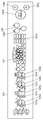
また、図1および図2に示したように、洗濯機29は、実質的に直方体に構成された筐体3を備えている。筐体3の内部には、実質的に円筒形に構成された水受け槽4が、吊り棒5によって吊り下げられている。水受け槽4内には、実質的に円筒形状に構成された洗濯兼脱水槽6が回転自在に内包されている。洗濯兼脱水槽6の底部には、撹拌翼7が、垂直方向に沿った軸の回りに回転自在に設けられている。
水受け槽4の外底部には、撹拌翼7を回転させるモータ8が設けられている。モータ8は、直流ブラシレスモータにより構成されている。モータ8と撹拌翼7との間には、動力切換機構9が設けられている。動力切換機構9は、洗濯時にはモータ8からの駆動力を減速して撹拌翼7に伝達し、脱水時にはモータ8からの駆動力を一対一に撹拌翼7に伝達する。
水受け槽4の上には、散水用の吐出部を構成するカバー体10が設けられている。また、筐体3の上方には、洗濯兼脱水槽6内に給水する給水弁11が設けられている。さらに、水受け槽4の下方には、水受け槽4内の洗濯水を排水する排水弁12が設けられている。
また、水受け槽4の外壁下部には、接続部13が設けられている。接続部13には、水受け槽4の水位を検知する水位検知器14が接続されている。水位検知器14は、接続部13における水圧を電気的な周波数に変換するように構成されている。
運転コース等のモードや各種機能の選択は、使用者が入力部26に入力することによって行われる。入力された情報に基づいて、表示部27に表示が行われ、使用者に報知される。
操作表示部37は、洗濯機29の前方上面に配置され、左右方向に延伸された形状を有している。操作表示部37は、洗濯機29の前方上面にある傾斜面上に設けられている。洗濯機29の前方上面内方には、洗濯機を制御する制御部39が配設されている。なお、図1においては、端末送受信部33が端末装置28から突出している例を示したが、このような形状に限定されない。端末送受信部33は、端末装置28の内部に内蔵されていてもよい。
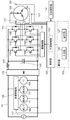
図3に示したように、洗濯機29のモータ8は、インバータ回路15によって駆動されている。インバータ回路15は、六個のスイッチング素子16A~16Fを有している。スイッチング素子16A~16Fは、それぞれ、パワートランジスタと逆導通ダイオードとによって構成される並列回路を有している。
電源17は、ダイオードブリッジ18、チョークコイル19、および平滑用コンデンサ20によって構成される直流電源変換装置を介して、インバータ回路15に電圧を供給する。電源17はまた、ポンプ60、給水弁11、排水弁12、および動力切換機構9にも電圧を供給する。
モータ8には、三個の位置検出器21が設けられている。位置検出器21は、モータ8の回転位置を検出する。
制御部39は、回転制御部23を有している。回転制御部23は、位置検出器21によって検出されたモータ8の回転位置と、水位検知器14によって検知された水受け槽4の水位とに基づいて、駆動回路24を制御する。駆動回路24は、回転制御部23からの指示に基づいて、インバータ回路15を駆動する。
ポンプ60、給水弁11、排水弁12、および動力切換機構9は、負荷駆動部25に接続されている。負荷駆動部25は、制御部39からの指示に基づいて、ポンプ60、給水弁11、排水弁12、および動力切換機構9を駆動する。
操作表示部37は、洗い時間、すすぎ回数、および脱水時間等が入力される入力部26と、入力部26に入力された、洗い時間、すすぎ回数、および脱水時間等を表示する表示部27とを有している。
また、図3において、端末装置28は、端末操作部30を備えている。端末操作部30は、ネットコース設定部31と転送開始ボタン32とを有している。
ネットコース設定部31は、洗い、すすぎ、および脱水の一連の工程のうち少なくとも一つの工程の内容を基本運転コースから変更することによって、洗濯機29によって実行されるネットコースの内容を設定する。
端末送受信部33は、ネットコース設定部31によって設定されたネットコースの内容を表す情報を、無線通信によって洗濯機29に送信する。無線通信方式としては、端末操作部30と端末送受信部33とに電圧を供給する電源を有し、送信する際のエネルギーを用いて電力供給を行う、近年携帯電話等に利用されているNFC(Near Field Communication)等によって通信を行うこともできるし、電源として電池を用いる構成としてもよい。
ネットコース設定部31は、端末表示部34と端末入力部35とを有している。端末表示部34には、ネットコースで設定されている洗い、すすぎ、および脱水の各工程の内容が表示される。また、端末入力部35によって、使用者が設定内容を変更することができる。運転状態判定部36は、端末送受信部33によって受信されたデータによって、洗濯機29の運転状態を判定する。
ここで、端末操作部30は、タッチパネルによって構成されており、ネットコース設定部31と転送開始ボタン32とを含むように形成されている。この端末装置28としては、携帯電話を用いることが可能である。なお、端末操作部30の詳細については、後述する(図6Aおよび図6B参照)。
洗濯機29は、制御部39を備えている。制御部39は、記憶部40を有している。記憶部40は、洗濯機送受信部38によって受信されたネットコースの内容を示す情報を記憶する。また、制御部39は、洗濯機送受信部38によって受信され、記憶部40に記憶された、ネットコースの内容を示す情報に基づいて、洗い、すすぎ、および脱水の一連の工程をプログラム制御する。
図4は、本発明の第1の実施の形態における洗濯機制御システム50の洗濯機29の操作表示部37を示す図である。
図4において、操作表示部37の入力部26は、洗い時間を設定する洗い時間設定スイッチ26a、すすぎ回数を設定するすすぎ回数設定スイッチ26b、および、脱水時間を設定する脱水時間設定スイッチ26cを有している。また、入力部26は、乾燥時間を設定する乾燥時間設定スイッチ26d、スタート・一時停止スイッチ26e、電源入りスイッチ26f、および電源切りスイッチ26g等を有するとともに、既存コース選択スイッチ26iを有している。
既存コース選択スイッチ26iによって、洗濯機29があらかじめ有しているコースのうちの一つを選択することができる。スタート・一時停止スイッチ26eによって、運転開始を指示することができる。電源入りスイッチ26f、および電源切りスイッチ26gによって、洗濯機29の電源を入れたり切ったりすることができる。
また、既存コース選択スイッチ26iで選択されたコースの洗い時間、すすぎ回数、および脱水時間の少なくとも一つを、洗い時間設定スイッチ26a、すすぎ回数設定スイッチ26b、および脱水時間設定スイッチ26cの少なくとも一つを押すことによって、変更設定して運転することもできる。
表示部27は、洗い時間表示部27a、すすぎ回数表示部27b、脱水時間表示部27c、および乾燥時間表示部27d等を有するとともに、端末装置28にてネットコースが選択された場合に点灯するネットコース表示部27fを有している。
また、表示部27は、複数の基本運転コース、および特別運転コースのそれぞれに対応する、複数の運転コース選択表示部27eを有している。ここで、特別運転コースは、入力部26への入力によって、洗い時間、すすぎ回数、および脱水時間の少なくとも一つが変更されることにより設定される。
複数の運転コース選択表示部27eは、それぞれ、発光ダイオードによって構成されている。基本運転コースには、例えば、「おまかせコース」、「お急ぎコース」、および「おうちクリーニングコース」が含まれている。「おまかせコース」は、最も標準的な運転コースであって、例えば洗い時間は「9分」に設定され、すすぎ回数は「注水2回」に設定され、脱水時間は「7分」に設定されている。
「お急ぎコース」は、急いで洗濯するための基本運転コースであって、例えば洗い時間は「3分」に設定され、すすぎ回数は「注水1回」に設定され、脱水時間は「3分」に設定されている。
「おうちクリーニングコース」は、ドライクリーニングを推奨されている衣類を家庭内の洗濯機29で洗うための基本運転コースであって、例えば洗い時間は「12分」に設定され、すすぎ回数は「ため2回」に設定され、脱水時間は「40秒」に設定されている。
特別運転コースにおいては、洗い時間、すすぎ回数、および脱水時間を、使用者が任意に設定することができる。運転コース選択表示部27eは、「おまかせコース」、「お急ぎコース」、「おうちクリーニングコース」および「特別運転コース」毎にそれぞれ設けられている。
操作表示部37は、さらに、洗濯機送受信部38を有しており、使用者が、ネットコースの内容を入力して設定した端末装置28を洗濯機送受信部38に近づけることにより、端末装置28に設けられた端末送受信部33によって情報が送信され、洗濯機29に入力される。なお、洗濯機送受信部38は、操作表示部37の横方向の中央に対して、右側に設けられた電源入りスイッチ26fの反対側である左側に配置されている。
ここで、操作表示部37における洗濯機送受信部38を中央よりも左側に配置する理由について説明する。操作表示部37の中で、電源入りスイッチ26fは、電源ライン(例えば電源電圧100Vの商用電源)と接続している。この電源ラインに他の電気機器が接続された場合、電源ラインにノイズが発生する可能性がある。この場合、例えば図5の下側に示すように、電源電圧にノイズ成分が重畳される。
図5は、本発明の第1の実施の形態における、電源電圧の正常波形とノイズ重畳波形とを示す図である。
洗濯機送受信部38による通信を行う際には、この重畳したノイズ成分の影響や、メイン電流が流れることによる磁界の影響等を受けることが想定される。
また、多くの使用者の利き手である右手で操作がしやすいように、電源入りスイッチ26f等の電源を入り切りするスイッチは、右側部に配置されることが多く、安全面から見ても、早くアクションが必要なスイッチは優先して右側に配置される。
例えば、使用者の利き手が右手の場合で、端末装置28として携帯電話を用いる場合を想定する。このとき、使用者は、利き手と反対の左手で携帯電話を持ちながら、洗濯機29側の設定作業を、利き手である右手で行うことになる。
端末装置28に設定された動作条件を、洗濯機29の洗濯機送受信部38に送信する際、使用者は、洗濯機送受信部38の近傍に端末装置28を近づける動作を行う。この動作を行う使用者の手は左手になる。この左手で端末装置28を近づける動作を行うにあたっては、中央よりも左側部に洗濯機送受信部38を配置することにより、使用者に使いやすい構成を実現することができる。
本実施の形態において、洗濯機29の横幅は640mm程度であるが、一般的には、およそ520mm~640mmの間に形成される。本実施の形態においては、電源入りスイッチ26fを操作表示部37の左右いずれか一方側に配置し、洗濯機送受信部38を電源入りスイッチ26fの配置位置とは反対側の、操作表示部37の左右いずれか他方側に配置する。これにより、洗濯機送受信部38の位置を、電源入りスイッチ26fに対して200mm以上離すことができるようになるので、電源入りスイッチ26f周辺から発生するノイズに対して、通信障害を受けにくい距離を十分に確保することができる。
なお、端末装置28に設けられた端末送受信部33と、洗濯機29に設けられた洗濯機送受信部38とは、例えばNFCを用いて情報を送受信することができる。
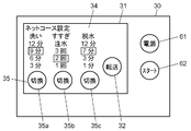
図6Aは、本発明の第1の実施の形態における洗濯機制御システム50の端末装置28の端末操作部30を示す図であり、図6Bは、同端末装置28のネットコース設定内容を転送する手順を説明する端末操作部30を示す図である。
図6Aおよび図6Bにおいて、使用者は、端末装置28の端末操作部30の電源ボタン61を押した後、ネットコース設定部31にて、端末入力部35の切換ボタン35a~35cを押すことにより、ネットコースの洗い時間、すすぎ回数、および脱水時間を設定することができる。使用者は、その設定内容を端末表示部34で確認することができる。
使用者は、設定が完了した後、転送開始ボタン32を押すことにより、設定内容を洗濯機29に送信することができる。転送開始ボタン32の機能については、図7のフローチャートを用いて後述する。なお、端末装置28は、携帯電話の機能に加えて、専用のアプリケーションを起動して機能させることにより、上述の動作を行うことができる。
以上のように構成された洗濯機制御システム50について、以下、その動作および作用を説明する。
図7は、本発明の実施の形態における洗濯機制御システム50の動作を示すフローチャートである。
図7において、使用者が、端末装置28の端末操作部30に設けられた電源ボタン61を押すと、図6Aに示したように、ネットコース設定の内容がネットコース設定部31に設けられた端末表示部34に表示される(S41)。
次に、ネットコース設定内容の初期値から、洗い時間、すすぎ回数、および脱水時間のいずれが変更されたか否かが判定される(S42)。
ステップS43は、洗い時間が変更された場合を示している。図6Aでは、端末入力部35であるタッチパネルの切換ボタン35aに使用者がタッチすることによって、洗い時間「6分」が洗い時間「9分」に変更された例を示している。
ステップS44は、すすぎ回数が変更された場合を示している。図6Aでは、端末入力部35であるタッチパネルの切換ボタン35bに使用者がタッチすることによって、すすぎ回数「1回」がすすぎ回数「2回」に変更された例を示している。
ステップS45では、脱水時間が変更された場合を示している。図6Aでは、端末入力部35であるタッチパネルの切換ボタン35cに使用者がタッチすることによって、脱水時間「3分」が脱水時間「7分」に変更された例を示している。
このとき、洗濯機29の電源は「切」状態である(S46)。電源が切れているので、洗濯機29は情報を受信できる状態(受信可能状態)にはなっていない。そのため、図6Aに示したように、転送開始ボタン32は表示されていない。
使用者が洗濯機29の電源入りスイッチ26fを押すことによって、洗濯機29の電源が「入」状態となる(S47)。洗濯機29は、洗濯機送受信部38により電源入データ(電源が入ったことを知らせるデータ)を端末装置28に送信する(S48)。
端末装置28は、電源入データを受信して、運転状態判定部36によって、洗濯機29の電源が入ったことを認知する(S49)。端末装置28は、洗濯機29が受信可能状態になったことを認知する。その結果、端末装置28は、図6Bに示すように、端末操作部30に転送開始ボタン32を表示する(S50)。
次に、使用者が転送開始ボタン32を押す(S51)と、NFCを用いて通信する場合には、使用者が端末装置28を洗濯機送受信部38に近づける(S52)。これにより、端末送受信部33からネットコース設定の全データが洗濯機29に送信される(S53)。
洗濯機29は、洗濯機送受信部38によってネットコース設定の全データを受信する(S54)。
そして、洗濯機29は、記憶部40にネットコース設定の全データを記憶する(S55)とともに、操作表示部37のネットコース表示部27fを点灯させる(S56)。記憶部40として不揮発性のメモリを用いることにより、洗濯機29の電源が遮断されても、全データを保存することができる。
次に、使用者が、スタート・一時停止スイッチ26eを押すことにより、洗濯機29は、受信したネットコース設定内容に基づいたシーケンスの運転を開始する(S57)。なお、端末装置28の端末操作部30に設けられたスタートボタン62を押すことによっても、洗濯機29は受信したネットコース設定内容に基づいたシーケンスを運転することができる。
(第2の実施の形態)
次に、本発明の第2の実施の形態について説明する。
次に、本発明の第2の実施の形態について説明する。
図8は、本発明の第2の実施の形態におけるドラム式の洗濯機129の斜視図である。なお、本実施の形態において、第1の実施の形態で説明した構成要素と同じ要素については、同じ符号を用いて、その説明を省略する。
洗濯機129と端末装置28とは、第1の実施の形態と同様に、無線通信によって接続されている。使用者は、洗濯機129の操作表示部37の入力部26を操作し、表示部27にて設定内容を確認しながら洗濯機129を制御することができる。また、端末装置28を操作することにより、洗濯機129を制御することもできる。このため、端末装置28には、洗濯機129と情報をやり取りする端末送受信部33が設けられ、洗濯機129の操作表示部37には、端末装置28と情報をやり取りする洗濯機送受信部38が設けられている。
操作表示部37は、洗濯機129の前方上面に左右方向に延伸された形状を有している。操作表示部37は、洗濯機129の前方上面にある傾斜面上に設けられている。また、洗濯機129の前方上面内方には、洗濯機を制御する制御部39が配設されている。操作表示部37や操作部、洗濯機送受信部38等の具体的な配置例については、例えば図4に示した配置を用いることができる。
洗濯機129の具体的な動作については、第1の実施の形態の洗濯機29と同様なので、詳細な説明は省略する。
使用者が、ネットコースの内容を入力して設定した端末装置28を洗濯機送受信部38に近づけることにより、端末装置28に設けられた端末送受信部33から情報が送信されて、洗濯機送受信部38を介して洗濯機129に入力される。なお、洗濯機送受信部38は、操作表示部37横方向の中央に対して、右側に設けられた電源入りスイッチ26fの反対側である左側に配置されている。
ここで、操作表示部37における洗濯機送受信部38の配置について説明する。第1の実施の形態と同様に、図5の下側に示したように、電源電圧にノイズ成分が多く重畳された状態になる場合があり、通信を行う際には、そのノイズ成分の影響や、メイン電流が流れることによる磁界の影響等を受けることが想定される。
そこで、通信に対する電源電圧のノイズ成分の影響や磁界の影響を受けないようにするために、電源入りスイッチ26fを操作表示部37の左右いずれか一方側に配置して、洗濯機送受信部38を電源入りスイッチ26fの配置位置とは反対側の操作表示部37の左右いずれか他方側に配置する。これにより、洗濯機送受信部38の位置を、電源入りスイッチ26fに対して、十分に距離を離すことができるので、電源入りスイッチ26f周辺から発生するノイズに対して、通信障害を受けにくい距離を十分に確保することができる。
また、本実施の形態においては、多くの使用者の利き手である右手で操作がしやすいように、電源入りスイッチ26f等の電源を入り切りするスイッチが右側に配置されており、安全面から見て、早くアクションが必要なスイッチは優先して右側に配置されている。
例えば、使用者の利き手が右手で、端末装置28として携帯電話を用いる場合を想定する。この場合、使用者は、利き手と反対の左手で携帯電話を持ちながら、洗濯機29側の設定作業を、利き手である右手で操作することになる。
使用者は、端末装置28で設定された動作条件を洗濯機129の洗濯機送受信部38に送信する際に、洗濯機送受信部38の近傍に端末装置28を近づける動作を行う。この近づける動作を行う使用者の手は左手となる。左手で端末装置28を近づける動作を行うにあたっては、中央よりも左側部に洗濯機送受信部38を配置することにより、使用者に使いやすい構成を実現することができる。
以上述べたように、各実施の形態においては、洗濯機29,129と端末装置28とで情報の通信を行って工程制御することができる。また、洗濯機29,129の洗濯機送受信部38は、操作表示部37の中心よりも左側に配置され、電源入りスイッチ26fは、操作表示部37の右側に配置される。これにより、使用者が洗濯機29,129から離れた場所からでも洗濯機29,129を設定できるので、操作し易く、かつ、洗濯機送受信部38が、電磁ノイズ等の影響を受けることなく、確実に情報の送受信を行うことができる。
また、洗濯機送受信部38を操作表示部37の傾斜面に配置することにより、洗濯機送受信部38に水が付着するのを防止することができる。このため、送信時に洗濯機送受信部38に近づける端末装置28にも水が付着することがなく、通信障害を防止することができる。
なお、各実施の形態においては、端末装置28を洗濯機29,129の洗濯機送受信部38に近づけて通信する洗濯機制御システム50について説明したが、本発明はこの例に限定されない。例えば、赤外線または電波を利用した短距離無線通信技術によって接続される構成であってもよい。
また、本実施の形態においては、洗濯機29,129を用いた場合の制御システムについて説明したが、プログラム制御される機器は洗濯機29,129に限定されるものではない。マイクロコンピュータを用いてプログラム制御される機器であれば他の機器にも適用可能であり、洗濯機29,129を用いた場合と同様の作用および効果を得ることができる。
以上述べたように、各実施の形態における洗濯機29,129および洗濯機制御システム50によれば、使用者の操作性を向上することができるとともに、電磁ノイズの影響を受けずに送受信機能を確実に動作させ、誤動作を起こさないような使い勝手のよい構成を実現することができる。
また、各実施の形態で説明した洗濯機29,129は、端末装置28と無線通信を行う洗濯機29,129である。洗濯機29,129は、洗濯機29,129の運転および通信の制御を行う制御部39と、洗濯機29,129の上部に左右方向に配置され、運転コースの設定および表示を行う操作表示部37とを備えている。操作表示部37は、電源を投入する電源入りスイッチ26fと、運転コースの設定内容を表示する表示部27と、端末装置28と通信を行う洗濯機送受信部38とを有している。制御部39は、端末装置28から送信された運転コースの情報を洗濯機送受信部38で受信し、運転コースの情報に基づいて、運転コースの表示および運転の制御を行う。電源入りスイッチ26fは、操作表示部37の左右いずれか一方側に配置され、洗濯機送受信部38は、電源入りスイッチ26fの配置された位置とは反対側の、操作表示部37の左右いずれか他方側に配置されている。
また、各実施の形態における洗濯機制御システム50は、端末装置28、および、端末装置28と無線通信を行う洗濯機29,129を備えている。洗濯機29,129は、洗濯機29,129の運転および通信の制御を行う制御部39と、洗濯機29,129の上部に左右方向に配置され、運転コースの設定および表示を行う操作表示部37とを有している。操作表示部37は、電源を投入する電源入りスイッチ26fと、運転コースの設定内容を表示する表示部27と、端末装置28と通信を行う洗濯機送受信部38とを有している。端末装置28は、洗濯機29,129と通信を行う端末送受信部33を有している。洗濯機29,129の制御部39は、端末装置28の端末送受信部33から送信された運転コースの情報を洗濯機送受信部38で受信し、運転コースの情報に基づいて、運転コースの表示および運転の制御を行う。電源入りスイッチ26fは、操作表示部37の左右いずれか一方側に配置され、洗濯機送受信部38は、電源入りスイッチ26fの配置された位置とは反対側の操作表示部37の左右いずれか他方側に配置されている。
これらの構成により、使用者が操作し易く、かつ、洗濯機送受信部38の配置を電磁ノイズを発生しやすい電源入りスイッチ26fから適度に距離を離すことにより、洗濯機送受信部38が電磁ノイズ等の影響を受けることなく確実に送信された信号を送受信することができる。
また、洗濯機送受信部38は、操作表示部37の中心よりも左側に配置され、電源入りスイッチ26fは、操作表示部37の中心よりも右側に配置されている。
このような構成により、利き手が右手である使用者にとって、操作のしやすい構成を実現することができる。
また、洗濯機送受信部38は、操作表示部37が有する傾斜面に配置されている。
このような構成により、洗濯機送受信部38に水が付着することを防止できるので、通信時に洗濯機送受信部38に近づける端末装置28にも水が付着することなく、通信障害を防止することができる。
以上述べたように、本発明によれば、離れた場所からでも洗濯機の運転コース等を設定できる、という格別な効果を奏することができる。よって、本発明は、洗濯兼脱水槽内に投入された衣類を洗濯する洗濯機、およびその洗濯機を制御する洗濯機制御システム等として有用である。また、電子制御が行なわれる他の電気機器の制御にも適用することができる。
3 筐体
4 水受け槽
5 吊り棒
6 洗濯兼脱水槽
7 撹拌翼
8 モータ
9 動力切換機構
10 カバー体
11 給水弁
12 排水弁
13 接続部
14 水位検知器
15 インバータ回路
17 電源
16A~16F スイッチング素子
18 ダイオードブリッジ
19 チョークコイル
20 平滑用コンデンサ
21 位置検出器
23 回転制御部
24 駆動回路
25 負荷駆動部
26 入力部
26a 洗い時間設定スイッチ
26b すすぎ回数設定スイッチ
26c 脱水時間設定スイッチ
26d 乾燥時間設定スイッチ
26e スタート・一時停止スイッチ
26f 電源入りスイッチ
26g 電源切りスイッチ
26i 既存コース選択スイッチ
27 表示部
27a 洗い時間表示部
27b すすぎ回数表示部
27c 脱水時間表示部
27d 乾燥時間表示部
27e 運転コース選択表示部
27f ネットコース表示部
28 端末装置
29,129 洗濯機
30 端末操作部
31 ネットコース設定部
32 転送開始ボタン
33 端末送受信部
34 端末表示部
35 端末入力部
35a~35c 切換ボタン
36 運転状態判定部
37 操作表示部
38 洗濯機送受信部
39 制御部
40 記憶部
50 洗濯機制御システム
60 ポンプ
61 電源ボタン
62 スタートボタン
Claims (4)
- 端末装置と無線通信を行う洗濯機であって、
前記洗濯機の運転および通信の制御を行う制御部と、
前記洗濯機の上部に左右方向に配置され、運転コースの設定および表示を行う操作表示部とを備え、
前記操作表示部は、電源を投入する電源入りスイッチと、前記運転コースの設定内容を表示する表示部と、前記端末装置と通信を行う洗濯機送受信部とを有し、
前記制御部は、前記端末装置から送信された前記運転コースの情報を前記洗濯機送受信部で受信し、前記運転コースの情報に基づいて、前記運転コースの表示および運転の制御を行い、
前記電源入りスイッチは、前記操作表示部の左右いずれか一方側に配置され、前記洗濯機送受信部は、前記電源入りスイッチの配置された位置とは反対側の、前記操作表示部の左右いずれか他方側に配置される
洗濯機。 - 前記洗濯機送受信部は、前記操作表示部の中心よりも左側に配置され、前記電源入りスイッチは、前記操作表示部の中心よりも右側に配置される
請求項1に記載の洗濯機。 - 前記洗濯機送受信部は、前記操作表示部が有する傾斜面に配置される
請求項1または請求項2に記載の洗濯機。 - 端末装置、および、前記端末装置と無線通信を行う洗濯機を備えた洗濯機制御システムであって、
前記洗濯機は、
前記洗濯機の運転および通信の制御を行う制御部と、
前記洗濯機の上部に左右方向に配置され、運転コースの設定および表示を行う操作表示部とを有し、
前記操作表示部は、電源を投入する電源入りスイッチと、前記運転コースの設定内容を表示する表示部と、前記端末装置と通信を行う洗濯機送受信部とを有し、
前記端末装置は、
前記洗濯機と通信を行う端末送受信部を有し、
前記洗濯機の前記制御部は、前記端末装置の前記端末送受信部から送信された前記運転コースの情報を前記洗濯機送受信部で受信し、前記運転コースの情報に基づいて、前記運転コースの表示および運転の制御を行い、
前記電源入りスイッチは、前記操作表示部の左右いずれか一方側に配置され、前記洗濯機送受信部は、前記電源入りスイッチの配置された位置とは反対側の前記操作表示部の左右いずれか他方側に配置される
洗濯機制御システム。
Priority Applications (2)
| Application Number | Priority Date | Filing Date | Title |
|---|---|---|---|
| EP13806528.9A EP2862972B1 (en) | 2012-06-18 | 2013-06-17 | Washing machine and washing machine control system |
| CN201380031758.5A CN104411874B (zh) | 2012-06-18 | 2013-06-17 | 洗衣机以及洗衣机控制系统 |
Applications Claiming Priority (2)
| Application Number | Priority Date | Filing Date | Title |
|---|---|---|---|
| JP2012136594A JP6019390B2 (ja) | 2012-06-18 | 2012-06-18 | 洗濯機制御システム |
| JP2012-136594 | 2012-06-18 |
Publications (1)
| Publication Number | Publication Date |
|---|---|
| WO2013190816A1 true WO2013190816A1 (ja) | 2013-12-27 |
Family
ID=49768430
Family Applications (1)
| Application Number | Title | Priority Date | Filing Date |
|---|---|---|---|
| PCT/JP2013/003757 Ceased WO2013190816A1 (ja) | 2012-06-18 | 2013-06-17 | 洗濯機および洗濯機制御システム |
Country Status (4)
| Country | Link |
|---|---|
| EP (1) | EP2862972B1 (ja) |
| JP (1) | JP6019390B2 (ja) |
| CN (1) | CN104411874B (ja) |
| WO (1) | WO2013190816A1 (ja) |
Cited By (3)
| Publication number | Priority date | Publication date | Assignee | Title |
|---|---|---|---|---|
| CN106154848A (zh) * | 2014-12-22 | 2016-11-23 | Lg电子株式会社 | 家用电器 |
| CN106715778A (zh) * | 2015-02-02 | 2017-05-24 | 夏普株式会社 | 洗涤系统 |
| CN108931944A (zh) * | 2017-05-27 | 2018-12-04 | 青岛海尔洗衣机有限公司 | 用于洗衣机的控制终端和洗衣机 |
Families Citing this family (5)
| Publication number | Priority date | Publication date | Assignee | Title |
|---|---|---|---|---|
| JP6159267B2 (ja) | 2014-01-20 | 2017-07-05 | アクア株式会社 | 洗濯機 |
| CN108625112A (zh) * | 2017-03-23 | 2018-10-09 | 青岛海尔滚筒洗衣机有限公司 | 一种洗衣机控制系统 |
| JP7438669B2 (ja) * | 2019-03-28 | 2024-02-27 | シャープ株式会社 | 洗濯機 |
| JP7516026B2 (ja) * | 2019-09-20 | 2024-07-16 | 日立グローバルライフソリューションズ株式会社 | 洗濯機 |
| JP2021094258A (ja) * | 2019-12-18 | 2021-06-24 | 東芝ライフスタイル株式会社 | 洗濯システム、サーバ、制御方法及びプログラム |
Citations (8)
| Publication number | Priority date | Publication date | Assignee | Title |
|---|---|---|---|---|
| JPH0542293A (ja) * | 1991-08-12 | 1993-02-23 | Toshiba Corp | 洗濯機 |
| JPH0580486U (ja) * | 1992-04-03 | 1993-11-02 | ソニー株式会社 | 洗濯機 |
| JPH05293293A (ja) * | 1992-04-21 | 1993-11-09 | Toshiba Corp | 洗濯機 |
| JP2002119788A (ja) | 2000-10-13 | 2002-04-23 | Matsushita Electric Ind Co Ltd | 洗濯乾燥機 |
| JP2003210890A (ja) * | 2002-01-23 | 2003-07-29 | Matsushita Electric Ind Co Ltd | 洗濯機 |
| JP2005034179A (ja) * | 2003-07-15 | 2005-02-10 | Matsushita Electric Ind Co Ltd | 機器の制御システム |
| JP2009226060A (ja) * | 2008-03-24 | 2009-10-08 | Sanyo Electric Co Ltd | 電気洗濯機 |
| JP2012105694A (ja) * | 2010-11-15 | 2012-06-07 | Panasonic Corp | 洗浄機器 |
Family Cites Families (5)
| Publication number | Priority date | Publication date | Assignee | Title |
|---|---|---|---|---|
| CN1465770A (zh) * | 2002-07-05 | 2004-01-07 | 乐金电子(天津)电器有限公司 | 洗衣机以及洗衣机的外部信号接收方法 |
| DE602005001194T3 (de) * | 2005-03-04 | 2012-01-12 | Electrolux Home Products Corporation N.V. | Haushaltsgeräteanordnung mit integriertem Betrieb |
| KR20070075548A (ko) * | 2006-01-13 | 2007-07-24 | 엘지전자 주식회사 | 무선통신 방식의 콘트롤러를 갖는 세탁 또는 세탁물 건조를위한 기계장치 |
| CN101545191B (zh) * | 2008-03-25 | 2012-03-07 | 松下家电研究开发(杭州)有限公司 | 具有蓝牙通信功能的洗衣机及通信工作方法 |
| KR20110128005A (ko) * | 2010-05-20 | 2011-11-28 | 엘지전자 주식회사 | 세탁물 처리기기 및 세탁물 처리 시스템 |
-
2012
- 2012-06-18 JP JP2012136594A patent/JP6019390B2/ja active Active
-
2013
- 2013-06-17 EP EP13806528.9A patent/EP2862972B1/en not_active Not-in-force
- 2013-06-17 CN CN201380031758.5A patent/CN104411874B/zh active Active
- 2013-06-17 WO PCT/JP2013/003757 patent/WO2013190816A1/ja not_active Ceased
Patent Citations (8)
| Publication number | Priority date | Publication date | Assignee | Title |
|---|---|---|---|---|
| JPH0542293A (ja) * | 1991-08-12 | 1993-02-23 | Toshiba Corp | 洗濯機 |
| JPH0580486U (ja) * | 1992-04-03 | 1993-11-02 | ソニー株式会社 | 洗濯機 |
| JPH05293293A (ja) * | 1992-04-21 | 1993-11-09 | Toshiba Corp | 洗濯機 |
| JP2002119788A (ja) | 2000-10-13 | 2002-04-23 | Matsushita Electric Ind Co Ltd | 洗濯乾燥機 |
| JP2003210890A (ja) * | 2002-01-23 | 2003-07-29 | Matsushita Electric Ind Co Ltd | 洗濯機 |
| JP2005034179A (ja) * | 2003-07-15 | 2005-02-10 | Matsushita Electric Ind Co Ltd | 機器の制御システム |
| JP2009226060A (ja) * | 2008-03-24 | 2009-10-08 | Sanyo Electric Co Ltd | 電気洗濯機 |
| JP2012105694A (ja) * | 2010-11-15 | 2012-06-07 | Panasonic Corp | 洗浄機器 |
Non-Patent Citations (1)
| Title |
|---|
| See also references of EP2862972A4 |
Cited By (7)
| Publication number | Priority date | Publication date | Assignee | Title |
|---|---|---|---|---|
| CN106154848A (zh) * | 2014-12-22 | 2016-11-23 | Lg电子株式会社 | 家用电器 |
| CN106154848B (zh) * | 2014-12-22 | 2020-01-31 | Lg电子株式会社 | 家用电器 |
| US11092937B2 (en) | 2014-12-22 | 2021-08-17 | Lg Electronics Inc. | Electric product |
| CN106715778A (zh) * | 2015-02-02 | 2017-05-24 | 夏普株式会社 | 洗涤系统 |
| CN106715778B (zh) * | 2015-02-02 | 2019-04-12 | 夏普株式会社 | 洗涤系统 |
| CN108931944A (zh) * | 2017-05-27 | 2018-12-04 | 青岛海尔洗衣机有限公司 | 用于洗衣机的控制终端和洗衣机 |
| CN108931944B (zh) * | 2017-05-27 | 2022-10-25 | 重庆海尔洗衣机有限公司 | 用于洗衣机的控制终端和洗衣机 |
Also Published As
| Publication number | Publication date |
|---|---|
| EP2862972A4 (en) | 2015-09-16 |
| EP2862972A1 (en) | 2015-04-22 |
| JP2014000187A (ja) | 2014-01-09 |
| EP2862972B1 (en) | 2017-08-30 |
| CN104411874A (zh) | 2015-03-11 |
| CN104411874B (zh) | 2016-11-23 |
| JP6019390B2 (ja) | 2016-11-02 |
Similar Documents
| Publication | Publication Date | Title |
|---|---|---|
| CN104411874B (zh) | 洗衣机以及洗衣机控制系统 | |
| KR102504104B1 (ko) | 세탁기, 그와 통신하는 단말기 및 그의 제어 방법 | |
| KR100555999B1 (ko) | 세탁기, 식기 세척 건조기 및 이들의 제어 시스템 | |
| US9722668B2 (en) | Home appliance, home appliance system, and method of controlling the same | |
| JP2015080657A (ja) | 洗濯機制御システム | |
| JP2014054279A (ja) | 洗濯機制御システム | |
| US20140018961A1 (en) | Pool system with user selectable communication protocols and method of operating the same | |
| KR101814328B1 (ko) | 가전기기의 원격조작시스템 | |
| JP2004097645A5 (ja) | ||
| EP2824230B1 (en) | Washing machine and communication system for washing machine | |
| KR20110137614A (ko) | 가전기기 및 그 동작방법 | |
| KR20110126437A (ko) | 가전기기 및 그 동작방법 | |
| JP5945693B2 (ja) | 洗濯機通信システム | |
| JP5945694B2 (ja) | 洗濯機通信システム | |
| JP2005034179A (ja) | 機器の制御システム | |
| JP6573094B2 (ja) | 洗濯機制御システム | |
| JP2009226060A (ja) | 電気洗濯機 | |
| JP2014023810A (ja) | 洗濯機制御システム | |
| JP6149251B2 (ja) | 洗濯機通信システム | |
| JP2005034412A (ja) | 洗濯機 | |
| JP4265344B2 (ja) | 洗濯機の制御システム | |
| JP2014023809A (ja) | 洗濯機 | |
| JP2005034413A (ja) | 洗濯機および洗濯機システム | |
| JP2005034180A (ja) | 洗濯機 | |
| JP2014195542A (ja) | 洗濯機 |
Legal Events
| Date | Code | Title | Description |
|---|---|---|---|
| 121 | Ep: the epo has been informed by wipo that ep was designated in this application |
Ref document number: 13806528 Country of ref document: EP Kind code of ref document: A1 |
|
| REEP | Request for entry into the european phase |
Ref document number: 2013806528 Country of ref document: EP |
|
| NENP | Non-entry into the national phase |
Ref country code: DE |