WO2013190817A1 - Manufacturing method of structure and manufacturing apparatus - Google Patents
Manufacturing method of structure and manufacturing apparatus Download PDFInfo
- Publication number
- WO2013190817A1 WO2013190817A1 PCT/JP2013/003759 JP2013003759W WO2013190817A1 WO 2013190817 A1 WO2013190817 A1 WO 2013190817A1 JP 2013003759 W JP2013003759 W JP 2013003759W WO 2013190817 A1 WO2013190817 A1 WO 2013190817A1
- Authority
- WO
- WIPO (PCT)
- Prior art keywords
- modeling
- material layer
- support member
- intermediate transfer
- manufacturing
- Prior art date
- Legal status (The legal status is an assumption and is not a legal conclusion. Google has not performed a legal analysis and makes no representation as to the accuracy of the status listed.)
- Ceased
Links
Images


Classifications
-
- B—PERFORMING OPERATIONS; TRANSPORTING
- B29—WORKING OF PLASTICS; WORKING OF SUBSTANCES IN A PLASTIC STATE IN GENERAL
- B29C—SHAPING OR JOINING OF PLASTICS; SHAPING OF MATERIAL IN A PLASTIC STATE, NOT OTHERWISE PROVIDED FOR; AFTER-TREATMENT OF THE SHAPED PRODUCTS, e.g. REPAIRING
- B29C64/00—Additive manufacturing, i.e. manufacturing of three-dimensional [3D] objects by additive deposition, additive agglomeration or additive layering, e.g. by 3D printing, stereolithography or selective laser sintering
- B29C64/10—Processes of additive manufacturing
- B29C64/106—Processes of additive manufacturing using only liquids or viscous materials, e.g. depositing a continuous bead of viscous material
- B29C64/112—Processes of additive manufacturing using only liquids or viscous materials, e.g. depositing a continuous bead of viscous material using individual droplets, e.g. from jetting heads
-
- B—PERFORMING OPERATIONS; TRANSPORTING
- B29—WORKING OF PLASTICS; WORKING OF SUBSTANCES IN A PLASTIC STATE IN GENERAL
- B29C—SHAPING OR JOINING OF PLASTICS; SHAPING OF MATERIAL IN A PLASTIC STATE, NOT OTHERWISE PROVIDED FOR; AFTER-TREATMENT OF THE SHAPED PRODUCTS, e.g. REPAIRING
- B29C64/00—Additive manufacturing, i.e. manufacturing of three-dimensional [3D] objects by additive deposition, additive agglomeration or additive layering, e.g. by 3D printing, stereolithography or selective laser sintering
- B29C64/10—Processes of additive manufacturing
- B29C64/106—Processes of additive manufacturing using only liquids or viscous materials, e.g. depositing a continuous bead of viscous material
- B29C64/124—Processes of additive manufacturing using only liquids or viscous materials, e.g. depositing a continuous bead of viscous material using layers of liquid which are selectively solidified
-
- B—PERFORMING OPERATIONS; TRANSPORTING
- B29—WORKING OF PLASTICS; WORKING OF SUBSTANCES IN A PLASTIC STATE IN GENERAL
- B29C—SHAPING OR JOINING OF PLASTICS; SHAPING OF MATERIAL IN A PLASTIC STATE, NOT OTHERWISE PROVIDED FOR; AFTER-TREATMENT OF THE SHAPED PRODUCTS, e.g. REPAIRING
- B29C64/00—Additive manufacturing, i.e. manufacturing of three-dimensional [3D] objects by additive deposition, additive agglomeration or additive layering, e.g. by 3D printing, stereolithography or selective laser sintering
- B29C64/10—Processes of additive manufacturing
- B29C64/141—Processes of additive manufacturing using only solid materials
-
- B—PERFORMING OPERATIONS; TRANSPORTING
- B29—WORKING OF PLASTICS; WORKING OF SUBSTANCES IN A PLASTIC STATE IN GENERAL
- B29C—SHAPING OR JOINING OF PLASTICS; SHAPING OF MATERIAL IN A PLASTIC STATE, NOT OTHERWISE PROVIDED FOR; AFTER-TREATMENT OF THE SHAPED PRODUCTS, e.g. REPAIRING
- B29C64/00—Additive manufacturing, i.e. manufacturing of three-dimensional [3D] objects by additive deposition, additive agglomeration or additive layering, e.g. by 3D printing, stereolithography or selective laser sintering
- B29C64/40—Structures for supporting 3D objects during manufacture and intended to be sacrificed after completion thereof
-
- B—PERFORMING OPERATIONS; TRANSPORTING
- B32—LAYERED PRODUCTS
- B32B—LAYERED PRODUCTS, i.e. PRODUCTS BUILT-UP OF STRATA OF FLAT OR NON-FLAT, e.g. CELLULAR OR HONEYCOMB, FORM
- B32B37/00—Methods or apparatus for laminating, e.g. by curing or by ultrasonic bonding
- B32B37/02—Methods or apparatus for laminating, e.g. by curing or by ultrasonic bonding characterised by a sequence of laminating steps, e.g. by adding new layers at consecutive laminating stations
-
- B—PERFORMING OPERATIONS; TRANSPORTING
- B33—ADDITIVE MANUFACTURING TECHNOLOGY
- B33Y—ADDITIVE MANUFACTURING, i.e. MANUFACTURING OF THREE-DIMENSIONAL [3D] OBJECTS BY ADDITIVE DEPOSITION, ADDITIVE AGGLOMERATION OR ADDITIVE LAYERING, e.g. BY 3D PRINTING, STEREOLITHOGRAPHY OR SELECTIVE LASER SINTERING
- B33Y30/00—Apparatus for additive manufacturing; Details thereof or accessories therefor
-
- G—PHYSICS
- G03—PHOTOGRAPHY; CINEMATOGRAPHY; ANALOGOUS TECHNIQUES USING WAVES OTHER THAN OPTICAL WAVES; ELECTROGRAPHY; HOLOGRAPHY
- G03G—ELECTROGRAPHY; ELECTROPHOTOGRAPHY; MAGNETOGRAPHY
- G03G15/00—Apparatus for electrographic processes using a charge pattern
- G03G15/22—Apparatus for electrographic processes using a charge pattern involving the combination of more than one step according to groups G03G13/02 - G03G13/20
- G03G15/221—Machines other than electrographic copiers, e.g. electrophotographic cameras, electrostatic typewriters
- G03G15/224—Machines for forming tactile or three dimensional images by electrographic means, e.g. braille, 3d printing
-
- B—PERFORMING OPERATIONS; TRANSPORTING
- B29—WORKING OF PLASTICS; WORKING OF SUBSTANCES IN A PLASTIC STATE IN GENERAL
- B29K—INDEXING SCHEME ASSOCIATED WITH SUBCLASSES B29B, B29C OR B29D, RELATING TO MOULDING MATERIALS OR TO MATERIALS FOR MOULDS, REINFORCEMENTS, FILLERS OR PREFORMED PARTS, e.g. INSERTS
- B29K2105/00—Condition, form or state of moulded material or of the material to be shaped
- B29K2105/0058—Liquid or visquous
-
- Y—GENERAL TAGGING OF NEW TECHNOLOGICAL DEVELOPMENTS; GENERAL TAGGING OF CROSS-SECTIONAL TECHNOLOGIES SPANNING OVER SEVERAL SECTIONS OF THE IPC; TECHNICAL SUBJECTS COVERED BY FORMER USPC CROSS-REFERENCE ART COLLECTIONS [XRACs] AND DIGESTS
- Y10—TECHNICAL SUBJECTS COVERED BY FORMER USPC
- Y10T—TECHNICAL SUBJECTS COVERED BY FORMER US CLASSIFICATION
- Y10T156/00—Adhesive bonding and miscellaneous chemical manufacture
- Y10T156/17—Surface bonding means and/or assemblymeans with work feeding or handling means
Definitions
- the present invention relates to a manufacturing method of a structure and a manufacturing apparatus.
- a method for making a three-dimensional object a method is known in which a material to be a three-dimensional object is stacked in layers and a final structure is manufactured.
- a material to be a support is provided so as to surround this layer, and patterning is performed.
- a support member (support) is thereby formed, and more material to be the three-dimensional object is stacked on the layers of the support and the three-dimensional object in the process of formation.
- the layer of the support and the layer of the three-dimensional object are made in different processes and of different materials, and therefore it is difficult to equalize the thickness of both layers in the process of formation. Since the amount of volume change due to the effect of temperature or the like varies depending on the material, it is supposed that the layer thickness differs between the layer to be the three-dimensional object and the layer of the support. In an object formed by stacking layers having different thicknesses, distortion is caused by the difference in layer thickness described above, and there is fear that the desired final shape of the three-dimensional object cannot be obtained.
- the present invention provides a manufacturing method by which a structure formed with a high degree of shape accuracy can be obtained.
- a manufacturing method of a structure includes providing a stack of a first material layer to be a part of the structure and a restricting member wherein the first material layer is provided on a surface of the structure in the process of formation, a part of the restricting member is provided on a surface of the first material layer in reverse of the surface of the structure in the process of formation, and the other part is provided above the surface of the structure in the process of formation, providing a support member so as to fill between the restricting member and the surface of the structure in the process of formation, removing the restricting member, and providing a second material layer to be a part of the structure on surfaces of the first material layer and the support member exposed by removing the restricting member.
- the surface of a layer to be a structure and the surface of a layer of the support member can be made accurately coplanar compared to the related art, and a structure formed with a high degree of shape accuracy can be obtained.
- Figs. 1A-1B are schematic diagrams showing an example of a stacking modeling apparatus according to a first embodiment of the present invention.
- Figs. 2A-2B are schematic diagrams showing an example of a stacking modeling apparatus according to a second embodiment of the present invention.
- Fig. 3 includes sectional views schematically showing steps of each of an example of the manufacturing method of a structure according to the first embodiment of the present invention and a manufacturing method of a structure of a comparative embodiment.
- Fig. 4 is a conceptual diagram showing the function of a stacking modeling apparatus according to an embodiment of the present invention.
- Figs. 5A-5F are schematic sectional views showing a part of the process of the manufacturing method of a structure in the stacking modeling apparatus according to the first embodiment of the present invention.
- Figs. 1A-1B are schematic diagrams showing an example of a stacking modeling apparatus according to a first embodiment of the present invention.
- Figs. 2A-2B are schematic diagrams showing an example of a stacking modeling
- FIGS. 6A-6F are schematic sectional views showing a part of the process of the manufacturing method of a structure in the stacking modeling apparatus according to the first embodiment of the present invention.
- Figs. 7A-7E are schematic sectional views showing a part of the process of the manufacturing method of a structure in the stacking modeling apparatus according to a third embodiment of the present invention.
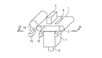
- Figs. 1A and 1B are schematic diagrams showing an example of a stacking modeling apparatus that is a manufacturing apparatus performing a manufacturing method of an object that is a three-dimensional structure, according to a first embodiment of the present invention.
- Fig. 1B is a perspective view of the whole apparatus
- Fig. 1A is a sectional view of the apparatus taken along line IA-IA of Fig. 1B perpendicularly to the surface of an intermediate transfer member 1.
- the intermediate transfer member 1 is conveyed by a conveyance mechanism 2.
- the support member 6 can be removed by a support removing mechanism 15.
- the support removing mechanism 15 may be provided inside the stacking modeling apparatus, or the stacked layers of modeling pattern and the support member 6 may be taken out of the stacking modeling apparatus, and the support member 6 may be removed using an external removing mechanism such as a chamber of solvent.
- the intermediate transfer member 1 can be made of a material having a high releasability from the modeling material. If the material of the intermediate transfer member 1 does not have releasability, for example, if the modeling material is transferred like the offset printing, an object can be created. From the viewpoint of modeling accuracy, all of the modeling material on the intermediate transfer member 1 can be transferred.
- the intermediate transfer member 1 can have not a little elasticity.
- Materials suitable as the intermediate transfer member 1 include silicone rubber and fluoro-rubber. Depending on the modeling material used for patterning, sometimes repelling occurs. Therefore, the intermediate transfer member 1 can be surface-treated according to the modeling material.
- the rubber hardness depends on the thickness of the elastic body. When the elastic body is thick, a hard rubber can be used. When the elastic body is thin, a relatively soft rubber can be used. When the elastic body is thick, a rubber having a hardness of about 80 degrees is suitable. When the intermediate transfer member 1 is treated like a belt as in the apparatus in the figures, a relatively soft rubber having a rubber hardness of about 50 degrees to 20 degrees can be used in the form of a thin film having a thickness of about 0.1 to 0.5 mm.
- a non-elastic polytetrafluoroethylene sheet or a film coated with a submicron thickness of a mold release agent is suitable.
- an ejection head having ejection ports that eject liquid is shown as a unit for forming a modeling pattern on the intermediate transfer member 1, and a method in which a modeling material is ejected from the ejection head onto a desired position is shown.
- the present invention is not limited to this.
- Examples of other units include a digital recording apparatus such as an electrophotographic device or a dispenser. Patterns can be formed using a patterning method using a printing plate, such as offset printing or screen printing, while changing the printing plate used. Patterns obtained by a method such as photolithography or electrolytic plating can be used without any problem.
- the patterning unit does not necessarily have to be located in the stacking modeling apparatus.
- the patterning unit can be selected based on the material of the object and the modeling accuracy.
- an inkjet which can perform patterning in a non-contact manner, is a very suitable patterning unit.
- Layer-like modeling patterns are formed using UV ink 4 as a molding material that is a material for formation.
- UV ink is solidified by irradiating with ultraviolet, and a lightweight and relatively strong object can be made.
- a patterning mechanism does not necessarily have to be disposed in the stacking apparatus, and layer-like patterns each layer of which is made using a different patterning mechanism in the same model according to the required accuracy and the material can also be stacked. By disposing different color materials in a layer-like pattern, a desired color of layer can be obtained.
- the modeling material can be freely selected within the range of application of the patterning unit used, and the patterning unit can be selected according to the material that one wants to use.
- Figs. 6A to 6F are schematic sectional views for explaining a part of the manufacturing process in the manufacturing apparatus of a structure according to an embodiment of the present invention, and show the same section as Fig. 1A.
- the object in the process of formation shown in Figs. 6A to 6F is the same as that shown in Figs. 1A and 1B but is simplified.
- the patterned modeling material shown in Fig. 1A is conveyed by the conveyance mechanism 2 onto the modeling table 8, is aligned with the object in the process of formation by an alignment unit (not shown), and is brought into a state shown in Fig. 6A.
- a stacking unit including a modeling container 7, a modeling table 8, a raising and lowering mechanism 9, a support filling mechanism 10, and a support receiver 11 moves upward and comes into contact with the ink pattern 4.
- the transfer surface 501 that comes into contact with the ink pattern 4 is a plane formed by a modeling pattern 502 that is a structure in the process of formation prepared by being previously transferred and stacked, and a support member 6 that is a solidified supporting material.
- the transfer surface 501 is held at a position lower than the upper end of the modeling container 7 by one layer thickness by the raising and lowering mechanism 9.
- the transfer surface 501 is raised until the upper end of the modeling container 7 comes into contact with the intermediate transfer member 1.
- the UV ink is sandwiched between two planes: the surface of the intermediate transfer member 1 and the transfer surface 501, and both the upper and lower surfaces of the UV ink are planarized with a high degree of accuracy. Only the modeling material is transferred at the time of stacking.
- the modeling material is held in this state and is irradiated with ultraviolet light from a UV lamp 12 (shown in Figs. 1A and 1B) disposed as a hardening and bonding unit.
- the UV ink is hardened with its surface planarized, is integrated with the previous modeling pattern, and forms an expanded modeling pattern 502. Hardening may be promoted by heat from the heater 13.
- a supporting material 5 for the support member is injected into the modeling container 7 in a liquid state.
- the modeling container 7 has a shape surrounding the modeling table 8 and restricts the filling range of the supporting material.
- the supporting material automatically flows into a space where the modeling pattern 502 does not exist, and therefore there is no need for alignment and layer thickness restriction. It is only necessary to stop injection when the space has been filled with the supporting material 5, just before the supporting material 5 overflows.
- the inner surface of the modeling container 7 needs to be prevented from adhering to the liquid supporting material used, and is preferably coated with polytetrafluoroethylene or the like.
- a liquid material that is solidified by an external stimulus is suitable.
- a material that can be easily removed from the object is suitable.
- External stimuli include heat, light, electricity, magnetism, and vibration.
- heat is easy to utilize the reversibility of the material.
- paraffin wax is used as a supporting material 6, it can be injected at a temperature above the melting point and can be solidified by lowering the temperature below the melting point. If the melting point of the supporting material is set below the melting point of the modeling material, the support can be easily removed by keeping the whole above the melting point of the supporting material and below the melting point of the modeling material for a predetermined length of time after the modeling is completed.
- the support can be injected using a normal liquid moving method such as pressure injection or reduced-pressure suction.
- a normal liquid moving method such as pressure injection or reduced-pressure suction.
- it is effective to increase the flowability by heating with the heater 13 as a temperature control mechanism, or to assist filling by applying minute high-frequency vibration with an ultrasonic vibrator or reducing the pressure.
- the injection of the supporting material can be basically performed every time a layer is stacked but sometimes need not be performed every time a layer is stacked.
- a support need not be used if the strength at the middle stage of modeling is sufficient.
- the supporting material 5 is solidified, is thereby integrated with the already formed support member, and forms an expanded support member 6.
- the intermediate transfer member 1 is peeled and removed from the upper surface 501.
- the support member 6 after solidification can hold the modeling pattern, and therefore even an isolated part forming an overhang can be fixed at a specified position. Therefore, the intermediate transfer member 1 can be peeled after the support is solidified.
- the upper surface 501 of the modeling pattern exposed by peeling the intermediate transfer member 1 has been restricted by the surface of the intermediate transfer member 1. Therefore, the support member 6 and the modeling pattern 502 can form an even, and highly accurately flat surface.
- This surface is moved by the raising and lowering mechanism 9 to a position lower than the upper end of the modeling container 7 by one layer thickness as shown in Fig. 6F in order to prepare to receive the next ink pattern in which ink is disposed in a cross-section of the object.
- the peeling of the intermediate transfer member 1, the lowering of the stacking unit, and the lowering of the transfer surface from the upper end of the modeling container 7 may be performed in any order.
- Figs. 1A and 1B after the transfer of an ink pattern is completed, the surface of the intermediate transfer member 1 is cleaned by the cleaner 12 as needed, and the intermediate transfer member 1 is repeatedly used.
- the intermediate transfer member 1 may be disposed after use, or may be recycled.
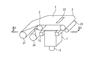
- Figs. 2A and 2B are schematic diagrams showing an example of a stacking modeling apparatus that is a manufacturing apparatus performing a manufacturing method of an object that is a three-dimensional structure, according to a second embodiment of the present invention.
- Fig. 2B is a perspective view of the whole apparatus
- Fig. 2A is a sectional view of the apparatus taken along line IIA-IIA of Fig. 2B perpendicularly to the surface of an intermediate transfer member 1.
- the apparatus of Fig. 2 does not have therein a patterning mechanism for forming an object.
- the stacking unit including a modeling table 8 supporting a support member 6 and an object, a raising and lowering mechanism 9, a modeling container 7, and an intermediate transfer member 1 is the same as that of the first embodiment.
- the support filling mechanism 10, the support receiver 11, and the roller 2 are also the same as those of the first embodiment.
- the modeling pattern 22 used can be made, for example, by partially applying polyester resin onto the intermediate transfer member 1 using a separate screen printing apparatus and then hardening the polyester resin.
- the intermediate transfer member 1 for example, a PET film thinly coated with silicone rubber can be used.
- the intermediate transfer member 1 on which a patterned layer for forming an object is already provided is set in the apparatus.
- an intermediate transfer member 1 wound into a roll is shown in Fig. 2A and 2B, sheet-like intermediate transfer members 1 stacked in order may be supplied one by one from a sorter.
- an apparatus that patterns a layer to be an object is separate from a stacking apparatus, less wasteful operation can be performed if the apparatuses differ in processing speed.
- an inspection apparatus for inspecting whether or not patterning is properly performed after patterning and before stacking, the inspection can be performed efficiently.
- the layer-like modeling pattern 22 on the intermediate transfer member 1 is solidified, and a mechanism that applies adhesive to the modeling pattern 22 in order to perform bonding at the time of stacking is disposed.
- the modeling pattern 22 comes into contact with the adhesive application mechanism by the conveyance by the conveyance mechanism, and passes over it, and adhesive is applied to the surface of the modeling pattern 22.
- adhesive can be selected according to the material of the object, based on indices such as contraction ratio and adhesive strength.
- indices such as contraction ratio and adhesive strength.
- a roll coater is depicted as an adhesive applicator, the present invention is not limited to this, and a spray-type application mechanism such as a spray can also be used.
- the bonding method at the time of stacking is not limited to application of adhesive.
- the process of stacking is the same as that of the first embodiment. After the transfer is completed, the intermediate transfer member is rewound by a rewinding mechanism 24, and is reused.
- the greatest advantageous effect obtained by the present invention is that, in each layer-like pattern, there is no difference in thickness between the modeling material and the material of the support member, and very high thickness accuracy can be reproduced.
- An object manufactured by this does not have any distortion and is highly accurate.
- the intermediate transfer member 1 serves as a restricting member that restricts the upper surfaces of the support member 6 and the modeling pattern when expanding the support member 6.
- a restricting member separate from the intermediate transfer member 1 may be used.
- the intermediate transfer member 1 may be removed, and a restricting member separate from the intermediate transfer member 1 may be brought into contact with the upper surface of the modeling pattern 502.
- the supporting material 5 may be injected, and a support may be formed while restricting the upper surface of the support member 6 with the restricting member so that the upper surface of the support member 6 is coplanar with the upper surface 501 of the modeling pattern.
- Fig. 3 includes sectional views schematically showing steps of each of an example of the manufacturing method of a structure according to the first embodiment of the present invention and a manufacturing method of a structure of a comparative embodiment, and illustrates the effect of the thickness accuracy of the layer-like patterns on the object.
- (a1) to (f1) show a comparative embodiment
- (a2) to (e2) show a stacking method according to an embodiment of the present invention.
- Fig. 3 (a1) shows a state where a layer-like modeling pattern 302 is formed on a base material 301.
- a support member 303 is disposed around the modeling pattern 302. This state is shown in Fig. 3 (b1).
- the support member hardens and a volume change is thereby caused.
- the volume change is expansion or contraction depending on the material. In general, contraction often occurs, and contraction is shown in the explanatory diagrams.
- the surface is open, and owing to the difference in contraction ratio between the materials of the modeling pattern 302 and the support member 303, as shown in Fig. 3 (c1), the upper surface of the modeling pattern 302 differs from the upper surface of the support member 303 in the height from the base material 301.
- Fig. 3 (d1) transfer is performed as shown in Fig. 3 (d1).
- the modeling pattern 302 is transferred together with the support member 303 from the base material 301 to another base material 304.
- a stacked object is formed. Since the thickness of each layer varies greatly from part to part, the layers 302 of modeling patterns are not aligned as desired as shown in Fig. 3 (e2), and are stacked in a distorted state as shown in Fig. 3 (f1).
- the embodiment of the present invention is as follows.
- a modeling pattern 202 is formed on a board member 201 (a2).
- a board member 204 is brought into contact with the surface of the modeling pattern 202 on the side opposite to the base material (b2).
- the material 203 of a support member is injected between the board-like board member 201 and the base material 204 (c2).
- the material of a support member is hardened (d2).
- the board member 201 functions as a restricting member that restricts the upper surfaces of the layer 202 of the modeling pattern and the layer 203 of the support member. Therefore, the surfaces of the layer of the support member and the layer of the modeling pattern can be formed at the same height and flat, and therefore a structure that does not have any distortion is manufactured as shown in Fig. 3 (e2).
- Fig. 4 shows an example of a control system of the apparatus for modeling a three-dimensional object of Figs. 1A and 1B.
- a CPU 101 is a main control unit of the entire system and controls each sections.
- a memory 102 includes a ROM storing a basic program of the CPU 101, and a RAM used for storing object data 104 taken in through an interface 103 and as a work area for data processing.
- the CPU 101 Upon receiving a modeling start signal, the CPU 101 starts the processing of converting the object data into slice data output according to set conditions, and performs communication for checking the states of the conveyance mechanism 2, inkjet 3, raising and lowering mechanism 9, support filling mechanism 10, and cleaner 12. If modeling can be started, the conveyance mechanism 2 and the raising and lowering mechanism 9 move to predetermined positions based on the information of the position detection 105, an ejection signal is sent to the inkjet 3, and modeling starts. When the stacking of layers to be a three-dimensional object is completed, communication for checking the state of the removing mechanism 15 is performed in order to remove the support member, and removal is started.
- Figs. 7A to 7E are schematic sectional views showing steps of a manufacturing method of an object according to a third embodiment of the present invention viewed at the position of a cross-section.
- the cross-sections are taken at the same position as Figs. 5A to 5F and 6A to 6F.
- stacking of the next structure is performed without removing the support member.
- Fig. 7A shows the same state as the state shown in Fig. 6F.
- modeling patterns 4 supported by a support member 6 are stacked.
- the stacking of modeling patterns 4 forming a structure is completed.
- the intermediate transfer member 1 and the modeling unit are moved closer to each other, and a material 5 of support member is injected so as to fill the space between the stacked modeling patterns 4 and the intermediate transfer member 1.
- the intermediate transfer member 1 is peeled, and as shown in Fig. 7C, the layer of the modeling pattern 4 is buried in the support member 6.
- a layer of a modeling pattern 1004 for making a new structure is provided on the surface exposed by peeling the intermediate transfer member 1.
- the next modeling pattern 1004 is stacked thereon.
- Example 1 slice data with a spacing of 25 micrometers was used.
- an intermediate transfer member 1 a belt made by forming a layer of fluoro-rubber (DAI-EL T530 manufactured by Daikin Industries, Ltd.) 150 micrometers in thickness on a PET film 50 micrometers in thickness was used.
- DAI-EL T530 fluoro-rubber manufactured by Daikin Industries, Ltd.
- a pattern of UV ink was applied on the intermediate transfer member 1 using an inkjet unit according to the first layer slice data of the object.
- the ink volume was adjusted to a constant value using clear ink.
- ink is irradiated relatively strongly in order to prevent color mixture and excessive spread of ink.
- the amount of light was adjusted so that flowability was kept until stacking.
- FIGS. 5A to 5F are schematic sectional views for explaining a part of the manufacturing process in the manufacturing apparatus of a structure according to an embodiment of the present invention, and show the same section as Fig. 1A.
- the upper end of the modeling container 7 was brought into contact with a part where there is no modeling pattern 4 of ink, of the surface of the intermediate transfer member 1 on which the ink pattern 4 is provided (Fig. 5B).
- the modeling pattern 4 on the intermediate transfer member 1 was a semisolid having a shape close to a hemisphere, the top thereof came into contact with the support member on the modeling table, and the modeling pattern 4 was compressed to 25 micrometers while being planarized.
- a slice pattern of the modeling pattern 4 was made.
- the space between the intermediate transfer member and the solidified support material was filled with a support material heated to about 60 degrees Celsius and melted (Paraffin wax 115 degrees Fahrenheit: commercially available).
- temperature was controlled by a heater (not shown) on the reverse side of the intermediate transfer member 1, and the flowability of the material 5 of support member was maintained.
- a part of the pre-existing support member melts.
- displacement does not occur.
- the surface of the intermediate transfer member is cleaned by a cleaner, and the intermediate transfer member is used repeatedly.
Landscapes
- Engineering & Computer Science (AREA)
- Chemical & Material Sciences (AREA)
- Materials Engineering (AREA)
- Manufacturing & Machinery (AREA)
- Physics & Mathematics (AREA)
- Mechanical Engineering (AREA)
- Optics & Photonics (AREA)
- General Physics & Mathematics (AREA)
- Micromachines (AREA)
- Pressure Sensors (AREA)
- Liquid Crystal (AREA)
Priority Applications (7)
| Application Number | Priority Date | Filing Date | Title |
|---|---|---|---|
| EP13807336.6A EP2736701B1 (de) | 2012-06-19 | 2013-06-17 | Verfahren zur herstellung einer struktur und herstellungsvorrichtung |
| RU2014107727/05A RU2564355C1 (ru) | 2012-06-19 | 2013-06-17 | Способ изготовления конструкции и устройство для изготовления |
| KR1020147005220A KR101567267B1 (ko) | 2012-06-19 | 2013-06-17 | 구조물의 제조 방법 및 제조 장치 |
| CN201380002895.6A CN103764377B (zh) | 2012-06-19 | 2013-06-17 | 构造物的制造方法及制造设备 |
| US14/240,009 US9636897B2 (en) | 2012-06-19 | 2013-06-17 | Manufacturing method of structure and manufacturing apparatus |
| BR112014004428A BR112014004428B8 (pt) | 2012-06-19 | 2013-06-17 | método de fabricação de estrutura e aparelho de fabricação |
| US15/476,441 US20170203510A1 (en) | 2012-06-19 | 2017-03-31 | Manufacturing method of structure and manufacturing apparatus |
Applications Claiming Priority (2)
| Application Number | Priority Date | Filing Date | Title |
|---|---|---|---|
| JP2012-137917 | 2012-06-19 | ||
| JP2012137917 | 2012-06-19 |
Related Child Applications (2)
| Application Number | Title | Priority Date | Filing Date |
|---|---|---|---|
| US14/240,009 A-371-Of-International US9636897B2 (en) | 2012-06-19 | 2013-06-17 | Manufacturing method of structure and manufacturing apparatus |
| US15/476,441 Continuation US20170203510A1 (en) | 2012-06-19 | 2017-03-31 | Manufacturing method of structure and manufacturing apparatus |
Publications (1)
| Publication Number | Publication Date |
|---|---|
| WO2013190817A1 true WO2013190817A1 (en) | 2013-12-27 |
Family
ID=49768431
Family Applications (1)
| Application Number | Title | Priority Date | Filing Date |
|---|---|---|---|
| PCT/JP2013/003759 Ceased WO2013190817A1 (en) | 2012-06-19 | 2013-06-17 | Manufacturing method of structure and manufacturing apparatus |
Country Status (8)
| Country | Link |
|---|---|
| US (2) | US9636897B2 (de) |
| EP (1) | EP2736701B1 (de) |
| JP (1) | JP6253273B2 (de) |
| KR (1) | KR101567267B1 (de) |
| CN (1) | CN103764377B (de) |
| BR (1) | BR112014004428B8 (de) |
| RU (1) | RU2564355C1 (de) |
| WO (1) | WO2013190817A1 (de) |
Cited By (5)
| Publication number | Priority date | Publication date | Assignee | Title |
|---|---|---|---|---|
| JP2015120343A (ja) * | 2013-12-20 | 2015-07-02 | ゼロックス コーポレイションXerox Corporation | エポキシ、硬化剤、および後で組み立てられる対象物の部品の3次元(3d)印刷 |
| WO2015168457A1 (en) * | 2014-04-30 | 2015-11-05 | Solid Fusion, LLC | Discrete 3d deposition printer |
| WO2016143334A1 (en) * | 2015-03-12 | 2016-09-15 | Canon Kabushiki Kaisha | Method and apparatus for manufacturing three-dimensional body |
| EP3010699A4 (de) * | 2013-06-18 | 2017-02-08 | Canon Kabushiki Kaisha | Verfahren zur herstellung eines bauteiles und herstellungsvorrichtung dafür |
| FR3050391A1 (fr) * | 2016-04-22 | 2017-10-27 | Nantes Ecole Centrale | Procede de fabrication additive et piece obtenue par un tel procede |
Families Citing this family (21)
| Publication number | Priority date | Publication date | Assignee | Title |
|---|---|---|---|---|
| JP6376831B2 (ja) * | 2013-06-20 | 2018-08-22 | キヤノン株式会社 | 構造体の製造方法 |
| JP2015150886A (ja) * | 2014-02-19 | 2015-08-24 | シャープ株式会社 | 積層造形装置及び積層造形方法 |
| JP6296901B2 (ja) * | 2014-05-27 | 2018-03-20 | キヤノン株式会社 | 立体物の製造方法およびその製造装置 |
| US20170087775A1 (en) | 2014-05-29 | 2017-03-30 | The Nippon Synthetic Chemical Industry Co., Ltd. | Support material for laminate shaping, product laminate-shaped by using the same, and laminate-shaped product production method |
| JP6463049B2 (ja) * | 2014-09-08 | 2019-01-30 | 学校法人慶應義塾 | 立体物製造方法及び立体物製造装置、並びに、これらに用いられる立体物支持部材、経時固化材若しくはその前駆体、又は凹部形成用部材 |
| CN104260353B (zh) * | 2014-09-24 | 2017-01-25 | 英华达(上海)科技有限公司 | 快速成型系统及其方法 |
| US10442138B2 (en) * | 2014-12-01 | 2019-10-15 | Canon Kabushiki Kaisha | Three-dimensional object manufacturing method and three-dimensional shaping apparatus |
| EP3120967B1 (de) | 2015-07-20 | 2019-06-12 | SLM Solutions Group AG | Verfahren und vorrichtung zur steuerung einer bestrahlungsanlage je nach werkstückgeometrie |
| DE102015117418A1 (de) * | 2015-10-13 | 2017-04-13 | M & R Beteiligungsgesellschaft mbH | Verfahren und Vorrichtung zur Herstellung eines Werkstücks |
| JP6733155B2 (ja) * | 2015-11-24 | 2020-07-29 | 三菱ケミカル株式会社 | 積層造形用サポート材およびそれを用いた積層造形物の製造方法 |
| US11130286B2 (en) * | 2016-09-07 | 2021-09-28 | Canon Kabushiki Kaisha | Three-dimensional manufacturing apparatus, three-dimensional manufactured object producing method, and container for three-dimensional manufacturing apparatus |
| US12251884B2 (en) * | 2017-04-28 | 2025-03-18 | Divergent Technologies, Inc. | Support structures in additive manufacturing |
| WO2019123629A1 (ja) * | 2017-12-22 | 2019-06-27 | 株式会社Fuji | 3次元積層電子デバイスの製造方法及び製造装置 |
| US11584065B2 (en) * | 2018-01-23 | 2023-02-21 | Rapidflight Holdings, Llc | Additively manufactured structure and method for making the same |
| WO2019203871A1 (en) * | 2018-04-17 | 2019-10-24 | Bmf Material Technology Inc. | Membrane-coating stereolithography |
| CN108973116A (zh) * | 2018-09-04 | 2018-12-11 | 广州捷和电子科技有限公司 | 一种3d打印机 |
| EP3819100B1 (de) * | 2019-11-08 | 2021-08-11 | Ivoclar Vivadent AG | Verfahren zum generativen aufbau von formkörpern durch stereolithographie |
| CN114829449A (zh) | 2019-11-28 | 2022-07-29 | 三菱化学株式会社 | 层叠造型用支承材料、使用其的层叠造型物和立体结构体的制造方法 |
| CN111497416B (zh) * | 2020-04-29 | 2022-05-06 | 辽宁鸿邦装备技术有限公司 | 一种高效低阻涤纶过滤材料的覆膜设备 |
| WO2023129659A1 (en) * | 2021-12-31 | 2023-07-06 | Evolve Additive Solutions, Inc. | Additive manufacturing method and article with improved heat transfer |
| JPWO2024117214A1 (de) | 2022-12-02 | 2024-06-06 |
Citations (4)
| Publication number | Priority date | Publication date | Assignee | Title |
|---|---|---|---|---|
| JPH08281808A (ja) * | 1995-04-17 | 1996-10-29 | Ricoh Co Ltd | 立体形状の製造方法 |
| JP2003053849A (ja) * | 2001-08-16 | 2003-02-26 | Konica Corp | 積層造形装置及び積層造形方法 |
| JP2003159754A (ja) * | 2001-11-27 | 2003-06-03 | Casio Comput Co Ltd | 三次元像生成方法及び三次元像生成装置 |
| JP2012040757A (ja) * | 2010-08-19 | 2012-03-01 | Sony Corp | 3次元造形装置、造形物及び造形物の製造方法 |
Family Cites Families (12)
| Publication number | Priority date | Publication date | Assignee | Title |
|---|---|---|---|---|
| US5876550A (en) | 1988-10-05 | 1999-03-02 | Helisys, Inc. | Laminated object manufacturing apparatus and method |
| US5637175A (en) | 1988-10-05 | 1997-06-10 | Helisys Corporation | Apparatus for forming an integral object from laminations |
| US5506607A (en) * | 1991-01-25 | 1996-04-09 | Sanders Prototypes Inc. | 3-D model maker |
| US5593531A (en) | 1994-11-09 | 1997-01-14 | Texas Instruments Incorporated | System, method and process for fabrication of 3-dimensional objects by a static electrostatic imaging and lamination device |
| US6136132A (en) * | 1997-03-26 | 2000-10-24 | Kinzie; Norman F. | Method and apparatus for the manufacture of three-dimensional objects |
| JP3161362B2 (ja) | 1997-05-01 | 2001-04-25 | 富士ゼロックス株式会社 | 微小構造体、その製造方法、その製造装置、基板および成形型 |
| JP3679634B2 (ja) * | 1998-11-30 | 2005-08-03 | キヤノン株式会社 | 多層構造物の製造方法および製造装置 |
| US7706910B2 (en) * | 2007-01-17 | 2010-04-27 | 3D Systems, Inc. | Imager assembly and method for solid imaging |
| DE102007016852A1 (de) * | 2007-04-10 | 2008-10-16 | Bioregeneration Gmbh | Verfahren zur Herstellung einer kristalline Cellulose umfassenden Struktur |
| CN101561674A (zh) * | 2009-05-22 | 2009-10-21 | 南京师范大学 | 多相材料零件的成型方法 |
| WO2011065920A1 (en) * | 2009-11-26 | 2011-06-03 | Yu En Tan | Process for building three-dimensional objects |
| DE202011003443U1 (de) | 2011-03-02 | 2011-12-23 | Bego Medical Gmbh | Vorrichtung zur generativen Herstellung dreidimensionaler Bauteile |
-
2013
- 2013-06-17 BR BR112014004428A patent/BR112014004428B8/pt active IP Right Grant
- 2013-06-17 RU RU2014107727/05A patent/RU2564355C1/ru active
- 2013-06-17 WO PCT/JP2013/003759 patent/WO2013190817A1/en not_active Ceased
- 2013-06-17 CN CN201380002895.6A patent/CN103764377B/zh active Active
- 2013-06-17 US US14/240,009 patent/US9636897B2/en active Active
- 2013-06-17 KR KR1020147005220A patent/KR101567267B1/ko active Active
- 2013-06-17 EP EP13807336.6A patent/EP2736701B1/de active Active
- 2013-06-19 JP JP2013128845A patent/JP6253273B2/ja active Active
-
2017
- 2017-03-31 US US15/476,441 patent/US20170203510A1/en not_active Abandoned
Patent Citations (4)
| Publication number | Priority date | Publication date | Assignee | Title |
|---|---|---|---|---|
| JPH08281808A (ja) * | 1995-04-17 | 1996-10-29 | Ricoh Co Ltd | 立体形状の製造方法 |
| JP2003053849A (ja) * | 2001-08-16 | 2003-02-26 | Konica Corp | 積層造形装置及び積層造形方法 |
| JP2003159754A (ja) * | 2001-11-27 | 2003-06-03 | Casio Comput Co Ltd | 三次元像生成方法及び三次元像生成装置 |
| JP2012040757A (ja) * | 2010-08-19 | 2012-03-01 | Sony Corp | 3次元造形装置、造形物及び造形物の製造方法 |
Non-Patent Citations (1)
| Title |
|---|
| See also references of EP2736701A4 * |
Cited By (7)
| Publication number | Priority date | Publication date | Assignee | Title |
|---|---|---|---|---|
| EP3010699A4 (de) * | 2013-06-18 | 2017-02-08 | Canon Kabushiki Kaisha | Verfahren zur herstellung eines bauteiles und herstellungsvorrichtung dafür |
| US10279546B2 (en) | 2013-06-18 | 2019-05-07 | Canon Kabushiki Kaisha | Method for manufacturing structural body and manufacturing apparatus therefor |
| JP2015120343A (ja) * | 2013-12-20 | 2015-07-02 | ゼロックス コーポレイションXerox Corporation | エポキシ、硬化剤、および後で組み立てられる対象物の部品の3次元(3d)印刷 |
| WO2015168457A1 (en) * | 2014-04-30 | 2015-11-05 | Solid Fusion, LLC | Discrete 3d deposition printer |
| WO2016143334A1 (en) * | 2015-03-12 | 2016-09-15 | Canon Kabushiki Kaisha | Method and apparatus for manufacturing three-dimensional body |
| US10773460B2 (en) | 2015-03-12 | 2020-09-15 | Canon Kabushiki Kaisha | Method and apparatus for manufacturing three-dimensional body |
| FR3050391A1 (fr) * | 2016-04-22 | 2017-10-27 | Nantes Ecole Centrale | Procede de fabrication additive et piece obtenue par un tel procede |
Also Published As
| Publication number | Publication date |
|---|---|
| EP2736701A1 (de) | 2014-06-04 |
| RU2014107727A (ru) | 2015-09-10 |
| BR112014004428B1 (pt) | 2020-08-25 |
| JP6253273B2 (ja) | 2017-12-27 |
| EP2736701A4 (de) | 2015-03-25 |
| KR101567267B1 (ko) | 2015-11-06 |
| CN103764377B (zh) | 2016-03-02 |
| US20170203510A1 (en) | 2017-07-20 |
| US20140182775A1 (en) | 2014-07-03 |
| BR112014004428A2 (pt) | 2017-03-28 |
| CN103764377A (zh) | 2014-04-30 |
| KR20140043831A (ko) | 2014-04-10 |
| EP2736701B1 (de) | 2017-08-09 |
| BR112014004428B8 (pt) | 2020-09-15 |
| JP2014024329A (ja) | 2014-02-06 |
| RU2564355C1 (ru) | 2015-09-27 |
| US9636897B2 (en) | 2017-05-02 |
Similar Documents
| Publication | Publication Date | Title |
|---|---|---|
| US9636897B2 (en) | Manufacturing method of structure and manufacturing apparatus | |
| US9770870B2 (en) | Method and apparatus for manufacturing structure | |
| JP6292857B2 (ja) | 構造体の製造方法 | |
| CN105829117B (zh) | 图案形成方法、图案形成用制造设备、结构体形成方法和用于其的制造设备 | |
| CN107073826B (zh) | 用于生成三维物体的系统和方法 | |
| JP4867772B2 (ja) | 化粧材 | |
| US20160059482A1 (en) | Apparatus for modeling three-dimensional object and method for modeling three-dimensional object | |
| JP6846204B2 (ja) | 印刷装置、印刷方法及び装飾物の製造方法 | |
| JP6489968B2 (ja) | 立体造形物の製造方法および立体造形物の製造装置 | |
| JP2007196668A (ja) | 立体物の製造方法、立体物、立体物製造用記録媒体、及び立体物の製造装置 | |
| CN105307841B (zh) | 结构体的制造方法和制造装置 | |
| US9849661B2 (en) | System and method for protection of printed images formed on surfaces of three-dimensional printed objects | |
| JP6584101B2 (ja) | 立体物の製造方法およびその製造装置 | |
| JP2008265233A (ja) | 化粧材及び化粧材の凹凸加飾形成方法 | |
| JP2013226481A (ja) | Uvインクジェットプリンタにより不規則な透明艶消し粒子表面を形成する方法及びuvインクジェットプリンタの完成印刷物 | |
| CN103317873B (zh) | Uv喷墨打印机生成不规则式透明雾面颗粒表面的方法及其完成的打印物 | |
| JP2016185618A (ja) | 三次元造形物の製造方法、三次元造形物製造装置および三次元造形物 |
Legal Events
| Date | Code | Title | Description |
|---|---|---|---|
| 121 | Ep: the epo has been informed by wipo that ep was designated in this application |
Ref document number: 13807336 Country of ref document: EP Kind code of ref document: A1 |
|
| WWE | Wipo information: entry into national phase |
Ref document number: 14240009 Country of ref document: US |
|
| ENP | Entry into the national phase |
Ref document number: 20147005220 Country of ref document: KR Kind code of ref document: A |
|
| REEP | Request for entry into the european phase |
Ref document number: 2013807336 Country of ref document: EP |
|
| REG | Reference to national code |
Ref country code: BR Ref legal event code: B01A Ref document number: 112014004428 Country of ref document: BR |
|
| NENP | Non-entry into the national phase |
Ref country code: DE |
|
| ENP | Entry into the national phase |
Ref document number: 112014004428 Country of ref document: BR Kind code of ref document: A2 Effective date: 20140225 |