WO2013190845A1 - Insulating wall, insulating box, and manufacturing method therefor - Google Patents
Insulating wall, insulating box, and manufacturing method therefor Download PDFInfo
- Publication number
- WO2013190845A1 WO2013190845A1 PCT/JP2013/003873 JP2013003873W WO2013190845A1 WO 2013190845 A1 WO2013190845 A1 WO 2013190845A1 JP 2013003873 W JP2013003873 W JP 2013003873W WO 2013190845 A1 WO2013190845 A1 WO 2013190845A1
- Authority
- WO
- WIPO (PCT)
- Prior art keywords
- heat insulation
- hole
- space
- box
- urethane
- Prior art date
- Legal status (The legal status is an assumption and is not a legal conclusion. Google has not performed a legal analysis and makes no representation as to the accuracy of the status listed.)
- Ceased
Links
Images


Classifications
-
- F—MECHANICAL ENGINEERING; LIGHTING; HEATING; WEAPONS; BLASTING
- F16—ENGINEERING ELEMENTS AND UNITS; GENERAL MEASURES FOR PRODUCING AND MAINTAINING EFFECTIVE FUNCTIONING OF MACHINES OR INSTALLATIONS; THERMAL INSULATION IN GENERAL
- F16L—PIPES; JOINTS OR FITTINGS FOR PIPES; SUPPORTS FOR PIPES, CABLES OR PROTECTIVE TUBING; MEANS FOR THERMAL INSULATION IN GENERAL
- F16L59/00—Thermal insulation in general
- F16L59/02—Shape or form of insulating materials, with or without coverings integral with the insulating materials
- F16L59/029—Shape or form of insulating materials, with or without coverings integral with the insulating materials layered
-
- F—MECHANICAL ENGINEERING; LIGHTING; HEATING; WEAPONS; BLASTING
- F25—REFRIGERATION OR COOLING; COMBINED HEATING AND REFRIGERATION SYSTEMS; HEAT PUMP SYSTEMS; MANUFACTURE OR STORAGE OF ICE; LIQUEFACTION SOLIDIFICATION OF GASES
- F25D—REFRIGERATORS; COLD ROOMS; ICE-BOXES; COOLING OR FREEZING APPARATUS NOT OTHERWISE PROVIDED FOR
- F25D23/00—General constructional features
- F25D23/08—Parts formed wholly or mainly of plastics materials
-
- B—PERFORMING OPERATIONS; TRANSPORTING
- B29—WORKING OF PLASTICS; WORKING OF SUBSTANCES IN A PLASTIC STATE IN GENERAL
- B29C—SHAPING OR JOINING OF PLASTICS; SHAPING OF MATERIAL IN A PLASTIC STATE, NOT OTHERWISE PROVIDED FOR; AFTER-TREATMENT OF THE SHAPED PRODUCTS, e.g. REPAIRING
- B29C44/00—Shaping by internal pressure generated in the material, e.g. swelling or foaming ; Producing porous or cellular expanded plastics articles
- B29C44/02—Shaping by internal pressure generated in the material, e.g. swelling or foaming ; Producing porous or cellular expanded plastics articles for articles of definite length, i.e. discrete articles
- B29C44/12—Incorporating or moulding on preformed parts, e.g. inserts or reinforcements
- B29C44/1228—Joining preformed parts by the expanding material
- B29C44/1233—Joining preformed parts by the expanding material the preformed parts being supported during expanding
-
- B—PERFORMING OPERATIONS; TRANSPORTING
- B29—WORKING OF PLASTICS; WORKING OF SUBSTANCES IN A PLASTIC STATE IN GENERAL
- B29C—SHAPING OR JOINING OF PLASTICS; SHAPING OF MATERIAL IN A PLASTIC STATE, NOT OTHERWISE PROVIDED FOR; AFTER-TREATMENT OF THE SHAPED PRODUCTS, e.g. REPAIRING
- B29C44/00—Shaping by internal pressure generated in the material, e.g. swelling or foaming ; Producing porous or cellular expanded plastics articles
- B29C44/34—Auxiliary operations
- B29C44/58—Moulds
- B29C44/588—Moulds with means for venting, e.g. releasing foaming gas
-
- B—PERFORMING OPERATIONS; TRANSPORTING
- B32—LAYERED PRODUCTS
- B32B—LAYERED PRODUCTS, i.e. PRODUCTS BUILT-UP OF STRATA OF FLAT OR NON-FLAT, e.g. CELLULAR OR HONEYCOMB, FORM
- B32B1/00—Layered products having a non-planar shape
-
- B—PERFORMING OPERATIONS; TRANSPORTING
- B32—LAYERED PRODUCTS
- B32B—LAYERED PRODUCTS, i.e. PRODUCTS BUILT-UP OF STRATA OF FLAT OR NON-FLAT, e.g. CELLULAR OR HONEYCOMB, FORM
- B32B5/00—Layered products characterised by the non- homogeneity or physical structure, i.e. comprising a fibrous, filamentary, particulate or foam layer; Layered products characterised by having a layer differing constitutionally or physically in different parts
- B32B5/18—Layered products characterised by the non- homogeneity or physical structure, i.e. comprising a fibrous, filamentary, particulate or foam layer; Layered products characterised by having a layer differing constitutionally or physically in different parts characterised by features of a layer of foamed material
- B32B5/20—Layered products characterised by the non- homogeneity or physical structure, i.e. comprising a fibrous, filamentary, particulate or foam layer; Layered products characterised by having a layer differing constitutionally or physically in different parts characterised by features of a layer of foamed material foamed in situ
-
- C—CHEMISTRY; METALLURGY
- C08—ORGANIC MACROMOLECULAR COMPOUNDS; THEIR PREPARATION OR CHEMICAL WORKING-UP; COMPOSITIONS BASED THEREON
- C08J—WORKING-UP; GENERAL PROCESSES OF COMPOUNDING; AFTER-TREATMENT NOT COVERED BY SUBCLASSES C08B, C08C, C08F, C08G or C08H
- C08J9/00—Working-up of macromolecular substances to porous or cellular articles or materials; After-treatment thereof
- C08J9/0004—Use of compounding ingredients, the chemical constitution of which is unknown, broadly defined, or irrelevant
- C08J9/0009—Phase change materials
-
- F—MECHANICAL ENGINEERING; LIGHTING; HEATING; WEAPONS; BLASTING
- F16—ENGINEERING ELEMENTS AND UNITS; GENERAL MEASURES FOR PRODUCING AND MAINTAINING EFFECTIVE FUNCTIONING OF MACHINES OR INSTALLATIONS; THERMAL INSULATION IN GENERAL
- F16L—PIPES; JOINTS OR FITTINGS FOR PIPES; SUPPORTS FOR PIPES, CABLES OR PROTECTIVE TUBING; MEANS FOR THERMAL INSULATION IN GENERAL
- F16L59/00—Thermal insulation in general
- F16L59/06—Arrangements using an air layer or vacuum
-
- F—MECHANICAL ENGINEERING; LIGHTING; HEATING; WEAPONS; BLASTING
- F25—REFRIGERATION OR COOLING; COMBINED HEATING AND REFRIGERATION SYSTEMS; HEAT PUMP SYSTEMS; MANUFACTURE OR STORAGE OF ICE; LIQUEFACTION SOLIDIFICATION OF GASES
- F25D—REFRIGERATORS; COLD ROOMS; ICE-BOXES; COOLING OR FREEZING APPARATUS NOT OTHERWISE PROVIDED FOR
- F25D23/00—General constructional features
- F25D23/06—Walls
- F25D23/062—Walls defining a cabinet
- F25D23/064—Walls defining a cabinet formed by moulding, e.g. moulding in situ
-
- B—PERFORMING OPERATIONS; TRANSPORTING
- B29—WORKING OF PLASTICS; WORKING OF SUBSTANCES IN A PLASTIC STATE IN GENERAL
- B29K—INDEXING SCHEME ASSOCIATED WITH SUBCLASSES B29B, B29C OR B29D, RELATING TO MOULDING MATERIALS OR TO MATERIALS FOR MOULDS, REINFORCEMENTS, FILLERS OR PREFORMED PARTS, e.g. INSERTS
- B29K2105/00—Condition, form or state of moulded material or of the material to be shaped
- B29K2105/04—Condition, form or state of moulded material or of the material to be shaped cellular or porous
- B29K2105/045—Condition, form or state of moulded material or of the material to be shaped cellular or porous with open cells
-
- B—PERFORMING OPERATIONS; TRANSPORTING
- B32—LAYERED PRODUCTS
- B32B—LAYERED PRODUCTS, i.e. PRODUCTS BUILT-UP OF STRATA OF FLAT OR NON-FLAT, e.g. CELLULAR OR HONEYCOMB, FORM
- B32B2266/00—Composition of foam
- B32B2266/02—Organic
- B32B2266/0214—Materials belonging to B32B27/00
- B32B2266/0278—Polyurethane
-
- B—PERFORMING OPERATIONS; TRANSPORTING
- B32—LAYERED PRODUCTS
- B32B—LAYERED PRODUCTS, i.e. PRODUCTS BUILT-UP OF STRATA OF FLAT OR NON-FLAT, e.g. CELLULAR OR HONEYCOMB, FORM
- B32B2307/00—Properties of the layers or laminate
- B32B2307/30—Properties of the layers or laminate having particular thermal properties
- B32B2307/304—Insulating
-
- B—PERFORMING OPERATIONS; TRANSPORTING
- B32—LAYERED PRODUCTS
- B32B—LAYERED PRODUCTS, i.e. PRODUCTS BUILT-UP OF STRATA OF FLAT OR NON-FLAT, e.g. CELLULAR OR HONEYCOMB, FORM
- B32B2607/00—Walls, panels
-
- C—CHEMISTRY; METALLURGY
- C08—ORGANIC MACROMOLECULAR COMPOUNDS; THEIR PREPARATION OR CHEMICAL WORKING-UP; COMPOSITIONS BASED THEREON
- C08J—WORKING-UP; GENERAL PROCESSES OF COMPOUNDING; AFTER-TREATMENT NOT COVERED BY SUBCLASSES C08B, C08C, C08F, C08G or C08H
- C08J2375/00—Characterised by the use of polyureas or polyurethanes; Derivatives of such polymers
- C08J2375/04—Polyurethanes
-
- F—MECHANICAL ENGINEERING; LIGHTING; HEATING; WEAPONS; BLASTING
- F25—REFRIGERATION OR COOLING; COMBINED HEATING AND REFRIGERATION SYSTEMS; HEAT PUMP SYSTEMS; MANUFACTURE OR STORAGE OF ICE; LIQUEFACTION SOLIDIFICATION OF GASES
- F25D—REFRIGERATORS; COLD ROOMS; ICE-BOXES; COOLING OR FREEZING APPARATUS NOT OTHERWISE PROVIDED FOR
- F25D2201/00—Insulation
- F25D2201/10—Insulation with respect to heat
- F25D2201/12—Insulation with respect to heat using an insulating packing material
- F25D2201/126—Insulation with respect to heat using an insulating packing material of cellular type
- F25D2201/1262—Insulation with respect to heat using an insulating packing material of cellular type with open cells
-
- Y—GENERAL TAGGING OF NEW TECHNOLOGICAL DEVELOPMENTS; GENERAL TAGGING OF CROSS-SECTIONAL TECHNOLOGIES SPANNING OVER SEVERAL SECTIONS OF THE IPC; TECHNICAL SUBJECTS COVERED BY FORMER USPC CROSS-REFERENCE ART COLLECTIONS [XRACs] AND DIGESTS
- Y10—TECHNICAL SUBJECTS COVERED BY FORMER USPC
- Y10T—TECHNICAL SUBJECTS COVERED BY FORMER US CLASSIFICATION
- Y10T428/00—Stock material or miscellaneous articles
- Y10T428/23—Sheet including cover or casing
- Y10T428/233—Foamed or expanded material encased
Definitions
- the present invention relates to a heat insulating wall, a heat insulating box, and a manufacturing method thereof.
- Patent Document 1 “open-cell urethane foam” is filled and foamed from the air inlet for blow molding of the heat insulating box into the heat insulating space of the heat insulating box, and then insulated by a vacuum exhaust device connected to the air inlet. Techniques have been proposed to evacuate the box and create a vacuum.
- an open cell means the structure where each bubble communicates.
- a closed cell refers to a structure in which each bubble is independently disconnected.
- the present inventor has found that the above-described prior art has the following problems from the following viewpoints. That is, the above-described conventional invention does not show a method for uniformly filling the space for heat insulation with open-cell urethane foam. For this reason, in the conventional invention, there exists a subject that the external appearance of a heat insulation box body deform
- the conventional invention does not disclose a method for preventing moisture from entering the space for heat insulation after the open-cell urethane foam is filled in the space for heat insulation. For this reason, in the conventional invention, there is a problem that the open-cell urethane foam is deteriorated by the invading moisture, and the heat insulation performance of the heat insulation box is lowered.
- the present invention has been made to solve such problems.
- the purpose is to provide a heat insulating wall, a heat insulating box, and a method for manufacturing the same, which can suppress external deformation and deterioration of heat insulating performance.
- a heat insulating wall includes a wall whose hollow portion is a space for heat insulation, and the heat insulating wall that is disposed in the wall and communicates the heat insulating space to the outside.
- the present invention it is possible to provide a heat insulating wall, a heat insulating box, and a manufacturing method thereof that can suppress external deformation and deterioration of heat insulating performance.
- FIG. 1A is a partial sectional view showing a part of the refrigerator cut along the line AA in FIG. 1A.
- the figure which showed typically the structural example of the open-cell urethane foam shown to FIG. 1A Magnified photograph showing the state between the pair of bubbles in the open cell urethane foam shown in FIG. 1A
- the figure for demonstrating the structure between the pair of bubbles represented to FIG. 2B Enlarged photograph showing the state where the first through-hole is formed in the bubble film part of FIG. 2B
- FIG. 2D Enlarged photo showing the state of the bubble skeleton in Fig. 2B
- FIG. 2F An enlarged photograph showing the state where the second through hole is formed in the bubble skeleton shown in FIG. 2F in more detail.
- skeleton part and 2nd through-hole which were represented to FIG. 2H The flowchart which shows the assembly example of the refrigerator shown to FIG. 1A Sectional drawing for demonstrating the integral foam molding of the heat insulation box shown to FIG. 1A
- FIG. 6A is a partial cross-sectional view showing a part of the refrigerator cut along the line CC in FIG. 6A.
- the figure which shows the sealing example 3 of the air hole of the refrigerator shown to FIG. 1A 7 is a partial sectional view showing a part of the refrigerator cut along the line DD in FIG. 7A.
- the figure which shows the sealing example 1 of the urethane liquid injection port of the refrigerator shown to FIG. 1A 8 is a partial cross-sectional view showing a part of the refrigerator cut along the line EE in FIG. 8A
- FIG. 8A The figure which shows the example 2 of sealing of the urethane liquid injection port of the refrigerator shown to FIG. 1A FIG.
- FIG. 9A is a partial cross-sectional view showing a part of the refrigerator cut along the line FF in FIG. 9A.
- the flowchart which shows the assembly example of the refrigerator provided with the heat insulation box which concerns on Embodiment 2 of this invention.
- FIG. 11A is a partial cross-sectional view showing a part of the refrigerator cut along the line GG in FIG. 11A
- Sectional drawing which shows the heat insulation wall (heat insulation box) which concerns on other embodiment of this invention
- Sectional drawing which shows the heat insulation box which concerns on other embodiment of this invention.
- the heat insulating wall according to the first aspect of the present invention includes a wall body in which a hollow portion is a space for heat insulation, a gas flow port disposed in the wall body and communicating with the space for heat insulation to the outside, and the heat insulating wall
- the space is filled with integral foam, and includes an open-cell urethane foam of a thermosetting urethane resin, and a sealing material that seals the gas circulation port.
- the “gas flow port” includes at least one of a urethane liquid injection port, an air hole, and an exhaust hole, which will be described later, and the following description of the gas flow port is the same.
- the “sealing material” includes at least one of an air hole sealing material, a urethane liquid inlet sealing material, and an exhaust hole sealing material, which will be described later. It is the same.
- the gas circulation port communicating with the heat insulation space to the outside can be used as an injection port for injecting the raw material of the open cell urethane foam and an air discharge port of the heat insulation space.
- the fluidity of the air in the space for heat insulation at the time of raw material injection and foaming is ensured, so that the open cell urethane foam is uniformly filled in the space for heat insulation.
- the gas flow port through which air enters from the outside is sealed with a sealing material, the intrusion of moisture from the gas flow port is prevented, and deterioration of the open-cell urethane foam due to moisture is prevented. .
- the bubbles in the open cell urethane foam are continuously communicated. By these, the external appearance deformation
- a heat insulating wall according to a second aspect of the present invention is the heat insulating wall according to the first aspect, wherein the open-cell urethane foam is formed in the vicinity of the interface between the core layer and the wall body and surrounds the core layer.
- Each of the core layer and the skin layer has a plurality of bubbles, a bubble film portion formed at a location where the bubbles are adjacent to each other, and a location where the bubbles are adjacent to each other.
- a bubble skeleton part formed so that a distance between the bubbles is larger than a thickness of the bubble film part, a first through hole formed so as to penetrate the bubble film part, and a bubble skeleton part
- the skin layer includes more of the bubble skeleton than the core layer, and the plurality of bubbles communicate with each other through the first through hole and the second through hole. It may be.
- a heat insulation box according to a third aspect of the present invention is constituted by one or a plurality of heat insulation walls according to the first or second aspect of the present invention, and the wall is accommodated in an outer case and the outer case. You may have a box.
- a heat insulation box according to a fourth aspect of the present invention is the heat insulation box according to the third aspect of the present invention, wherein the gas circulation port is used for venting air in the heat insulation space in the process of filling the heat insulation space with the open cell urethane foam.
- the hole diameter of the air hole may be smaller than the hole diameter of the urethane liquid inlet.
- the air hole may be provided in the inner box, and the urethane liquid inlet may be provided in the outer box.
- the gas circulation port further includes an exhaust hole for evacuating the heat insulation space
- the sealing material may further include an exhaust hole sealing material that seals the exhaust holes.
- the space for heat insulation filled with the open-cell urethane foam is evacuated through the exhaust hole, whereby the space for heat insulation is formed into a vacuum heat insulation layer, and the heat insulation property of the heat insulation box can be improved.
- the exhaust hole is sealed together with the air hole and the urethane liquid inlet, the degree of vacuum of the heat insulating space can be maintained, and a decrease in the heat insulating property of the heat insulating box can be suppressed.
- the urethane liquid inlet may be used as the exhaust hole.
- the heat insulation box according to the ninth aspect of the present invention may further include a gas adsorbing device disposed in the heat insulation space in any one of the third to eighth aspects of the present invention.
- the gas adsorption function of the gas adsorption device shortens the exhaust distance of the open-cell urethane foam and realizes efficient vacuuming. Can do.
- a small amount of residual gas existing in the heat insulation space can be adsorbed by the gas adsorption device, and the degree of vacuum of the heat insulation space can be easily maintained.
- the gas adsorption device includes an adsorbent that adsorbs carbon dioxide gas, and the adsorbent is made of ZSM-5 zeolite ion-exchanged with at least one of barium and strontium. It may be.
- the open-cell urethane foam in which the raw material is integrally foam-molded with the wall body and filled in the heat insulation space, has a plurality of bubbles, a bubble film portion formed at a location where the bubbles are adjacent, and the bubbles are adjacent to each other A bubble skeleton part formed at a position where the distance between adjacent bubbles is larger than the thickness of the bubble film part, and a first through hole formed so as to penetrate the bubble film part A second through hole formed so as to penetrate the bubble skeleton, wherein the plurality of bubbles communicate with each other through the first through hole and the second through hole.
- the composition for forming the through hole is A plurality of polyol mixtures, a polyisocyanate that undergoes a polymerization reaction with the polyol mixture to form a thermosetting urethane resin that constitutes the cell membrane and the cell skeleton, a foaming agent that forms the cells, And a non-affinity powder for forming the second through-hole.
- the open cell urethane foam can be uniformly filled in the space for heat insulation.
- the raw material of the open-cell urethane foam includes a plurality of polyol mixtures having different compositions, polyisocyanate, a foaming agent, and powder.
- a method for manufacturing a heat insulating box according to the eleventh aspect of the present invention, wherein a gas circulation port disposed in the wall body and communicating with the heat insulating space is sealed with a sealing material. And may stop further.
- the heat insulating box manufacturing method wherein the gas flow port is configured to fill the heat insulating space with the air in the heat insulating space in the process of filling the heat insulating space with the open cell urethane foam.
- An air hole for extracting, and a urethane liquid injection port for injecting the raw material, and the sealing material seals the air hole sealing material for sealing the air hole and the urethane liquid injection port.
- sealing the gas flow port with the sealing material after injecting the raw material from the urethane liquid injection port into the heat insulation space. Sealing the hole with the air hole sealing material and sealing the urethane liquid inlet with the urethane liquid inlet sealing material after sealing the air hole. Good.
- the air in the heat insulation space is discharged from the air holes, and the open cell foam is uniformly filled in the heat insulation space. be able to. And if a urethane liquid injection port is sealed after sealing an air hole, the space for heat insulation can be sealed, and it will prevent that a continuous gas urethane foam deteriorates with the penetrated water
- the heat insulating box manufacturing method wherein the gas circulation port has an exhaust hole for evacuating the heat insulating space filled with the open cell urethane foam.
- the sealing material further includes an exhaust hole sealing material for sealing the exhaust hole, and after sealing the air hole, the heat insulating space is evacuated through the exhaust hole. Sealing the gas flow port with the sealing material further includes sealing the exhaust hole with the exhaust hole sealing material after performing the evacuation. May be.
- a heat insulating box manufacturing method according to any one of the eleventh to fourteenth aspects, wherein a gas adsorbing device is disposed in the heat insulating space before the raw material is injected. There may be further provided.
- the gas adsorption device when the gas adsorbing device is disposed in the heat insulating space and the raw material of the open cell urethane foam is injected into the heat insulating space, the open cell urethane foam and the gas adsorbing device are provided in the heat insulating space. For this reason, a gas adsorption device exhibits a gas adsorption function and can prevent deterioration of open-cell urethane foam. Also, when evacuating the space for heat insulation filled with open-cell urethane foam, the gas adsorption device absorbs the gas, shortening the exhaust distance of the open-cell urethane foam and realizing efficient vacuuming Can do. Furthermore, the gas adsorption device adsorbs a small amount of residual gas present in the heat insulation space after evacuation, and it becomes easier to maintain the degree of vacuum in the heat insulation space.
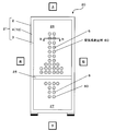
- FIG. 1A is a front view of a refrigerator 20 provided with a heat insulating box 21 according to Embodiment 1 of the present invention.
- FIG. 1B is a partial cross-sectional view showing a part of the refrigerator 20 cut along the line AA in FIG. 1A. 1A and 1B, the height direction of the refrigerator 20 is the vertical direction, the width direction of the refrigerator 20 is the left-right direction, and the thickness direction of the refrigerator 20 is the front-back direction.
- the refrigerator 20 includes a heat insulating box 21 and a door (not shown) attached to the heat insulating box 21.
- the heat insulation box 21 is a box-shaped container whose front is open and has an internal space. The internal space is partitioned into an upper refrigerator compartment 26 and a lower freezer compartment 27 by a partition plate 25, for example.
- a single-door or double-open rotary door (not shown) is attached to the heat insulating box 21 so as to close the refrigerator compartment 26 so that it can be opened and closed.
- a drawer-type door (not shown) is attached to the heat insulating box 21 so as to close the freezer compartment 27 so that it can be opened and closed in the front-rear direction.
- the refrigerator 20 is provided with a refrigeration cycle (not shown) including a compressor, an evaporator, and a condenser.
- the internal space of the refrigerator 20 is not limited to the compartment between the refrigerator compartment 26 and the freezer compartment 27.
- the internal space of the refrigerator 20 may be partitioned by a plurality of partition plates into a plurality of storage rooms (refrigeration room, freezer room, ice making room, vegetable room, etc.) having different uses.
- the heat insulation box 21 is composed of one or a plurality of heat insulation walls.
- the heat insulating wall since the heat insulating box 21 is constituted by one heat insulating wall, the heat insulating wall has the entire shape of the heat insulating box 21.
- the box-shaped heat insulating box 21 may be formed by combining a plurality of heat insulating walls.
- the heat insulation box 21 includes a hollow wall body and an open-cell urethane foam 4 filled in a heat insulation space in the wall body.
- the open-cell urethane foam 4 constitutes the core material of the heat insulation layer in the heat insulation box 21.
- the wall body includes an outer box 2 and an inner box 3 accommodated in the outer box.
- the outer box 2 is made of metal (for example, iron)
- the inner box 3 is made of a resin such as hard resin (for example, ABS (Acrylonitrile Butadiene Styrene) resin). It is formed.
- both the outer box 2 and the inner box 3 may be formed of metal.
- both the outer box 2 and the inner box 3 may be formed of resin.
- a space between the outer box 2 and the inner box 3, that is, a hollow portion in the wall is used as a heat insulating space.
- the wall body is not limited to the two components of the outer box 2 and the inner box 3 as long as it has a space for heat insulation inside.
- the wall body may be formed by one or three or more components.
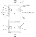
- urethane liquid injection ports 5 are disposed at a total of four locations in the upper right portion, the upper left portion, the lower right portion, and the lower left portion of the outer case 2. .
- the urethane liquid injection port 5 is a gas communication port that penetrates the back plate of the outer box 2 and communicates the heat insulating space 10 with the outside, and injects the raw material (urethane liquid) of the open-cell urethane foam 4. Used for.
- These four urethane liquid injection ports 5 are arranged symmetrically on the back plate of the outer box 2.
- the urethane liquids injected from the respective urethane liquid injection ports 5 merge at a substantially central portion of the heat insulating space 10 between the outer box 2 and the inner box 3 of the refrigerator 20.
- the urethane foam merge part 4a the hollow part of the refrigerator 20 where the urethane liquid inject
- This urethane foam joining part 4a is formed in a central shape of the refrigerator 20 so as to be concentrated in a circular shape.
- the number and arrangement of the urethane liquid injection ports 5 are not limited to the above-described four locations as long as the urethane foam joining portion 4a is formed so as to be concentrated at one central portion.
- a plurality of air holes 6 are intensively arranged at the location of the back plate of the inner box 3 corresponding to the urethane foam joining portion 4a.
- This air hole 6 is a gas communication port that penetrates the back plate of the inner box 3 and communicates the heat insulation space 10 and the outside.
- the air hole 6 is insulated when the urethane liquid is injected and when the urethane liquid is foamed. Used to exhaust the air in the working space 10.
- a plurality of air holes 6 are also arranged at the location of the back plate of the inner box 3 adjacent to the urethane foam merging portion 4a.
- the number of air holes 6 arranged in a line in the left-right direction from the upper side (the refrigerator compartment 26 side) toward the urethane foam merging portion 4a increases in order of 2, 4, and 6. is doing.
- the number of air holes 6 arranged in a line in the left-right direction from the lower side (freezer compartment 27 side) toward the urethane foam merging portion 4a increases from two to four. .
- the total number of the air holes 6 is 40, for example.
- the hole diameter of the air hole 6 is smaller than the hole diameter of the urethane liquid inlet 5 from the viewpoint of preventing urethane liquid leakage.
- the urethane liquid inlet 5 is connected to the tip of a liquid supply hose 41 of a urethane liquid supply device 40 described later.
- the hole diameter of the urethane liquid inlet 5 has a size corresponding to the hole diameter at the tip of the liquid supply hose 41, and is set to 30 mm, for example.
- the hole diameter of the air hole 6 is set to 1.0 mm, for example.
- the air hole 6 has a hole diameter of 1.0 (mm) or more, the urethane liquid easily leaks.
- the air hole 6 has a hole diameter of 0.5 (mm) or less, the exhaust effect is reduced. Therefore, by adopting 1.0 (mm) as the hole diameter of the air hole 6, it is possible to improve the exhaust effect with the smallest possible number while suppressing the urethane leakage defect.
- an airway cover or the like may be provided.
- the air holes 6 arranged on the back plate of the inner box 3 are hidden from human eyes.
- the air holes 6 are arranged on the back plate of the inner box 3 in order to enhance the appearance design of the refrigerator 20, but may be arranged on the back plate of the outer box 2.
- the open-cell urethane foam 4 is an open-cell resin body made of a thermosetting resin, and is filled in the heat insulation space 10 by integral foaming in the heat insulation space 10.
- integrated foaming refers to injecting the raw material (urethane liquid) of the open-cell urethane foam 4 into the heat insulating space 10 formed by at least a part of the wall, and foaming and solidifying the raw material in the heat insulating space 10. It means that The integrally foamed molded product is a heat insulating box 21 in which the open-cell urethane foam 4 is fixed to the wall bodies 2 and 3 as skin materials, and these are integrally formed.
- the open-celled urethane foam 4 supports the outer box 2 and the inner box 3 while holding the heat insulating space 10 therebetween while insulating the space between the outer box 2 and the inner box 3. That is, the open-cell urethane foam 4 functions as a core material (core member).
- the porosity of the open cell urethane foam 4 is, for example, 95% or more. As the porosity increases, the heat insulating property of the open-cell urethane foam 4 improves, but the mechanical strength for supporting the outer box 2 and the inner box 3 decreases. For this reason, the porosity of the open-cell urethane foam 4 is determined in consideration of heat insulation and mechanical strength.
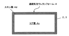
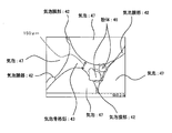
- FIG. 2A is a diagram schematically showing an example of the structure of the open-cell urethane foam 4 shown in FIG. 1A.
- the open-cell urethane foam 4 has a core layer 4c and a skin layer 4d that covers the outer periphery of the core layer 4c.
- the core layer 4c has a lower density than the skin layer 4d by including more bubbles 47 (FIGS. 2B and 2C) than the skin layer 4d.
- the core layer 4 c is located at the center of the open cell urethane foam 4.
- the skin layer 4 d is formed in the vicinity of the inner surfaces of the outer box 2 and the inner box 3.
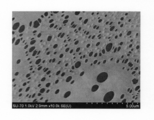
- FIG. 2B is an enlarged photograph showing a state between a pair of bubbles 47 in the open cell urethane foam 4 shown in FIG. 2A.
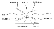
- FIG. 2C is a diagram for explaining a configuration between the pair of bubbles 47 illustrated in FIG. 2B.
- the core layer 4c and the skin layer 4d shown in FIG. 2A include a plurality of bubbles 47, a bubble film portion 42, and a bubble skeleton portion 43, respectively, as shown in FIGS. 2B and 2C.
- the ratio occupied by the bubble film portion 42 is larger in the core layer 4c than in the skin layer 4d.
- the ratio of the bubble skeleton 43 is higher in the skin layer 4d that is not sufficiently foamed than in the core layer 4c. For this reason, the ratio of the bubble skeleton part 43 to the bubble film part 42 is higher in the skin layer 4d than in the core layer 4c.
- the bubbles 47 are fine bubbles smaller than 1000 ⁇ m, for example. Since the bubbles 47 communicate with each other through a first through hole 44 and a second through hole 45 described later, the bubbles 47 are continuous. In the open-cell urethane foam 4 having the same density, the smaller and continuous the bubbles 47, the longer the heat transfer route in the open-cell urethane foam 4, and the heat insulation of the open-cell urethane foam 4 is improved. However, the smaller the size of the bubbles 47, the larger the fluid resistance (exhaust resistance) when decompressing the internal space such as the bubbles 47 in the open-cell urethane foam 4, and the power and time for exhaustion increase. Therefore, the size of the air bubbles 47 is determined in consideration of the heat insulating property and the exhaust efficiency of the open cell urethane foam 4.
- the bubble film portion 42 is formed at a location where the bubbles 47 are close to each other, and is formed in a film shape between a pair of the bubbles 47 facing each other.
- the thickness of the bubble film part 42 is, for example, about 3 ⁇ m as typically shown in the upper right part and the lower left part of FIGS. 2B and 2C. And thin.
- the bubble skeleton 43 is formed at a location where the bubbles 47 are adjacent, as typically shown in the center of FIGS. 2B and 2C.
- the thickness of the bubble skeleton portion 43 (distance between the pair of bubbles 47) is larger than the bubble film portion 42, for example, about 150 ⁇ m (FIGS. 2F and 2G). For this reason, the bubble skeleton 43 is formed between a plurality of pairs of bubbles 47 facing each other.
- the bubble film portion 42 between the pair of bubbles 47 and the bubble film portion 42 between the other pair of bubbles 47 are continuous in the bubble skeleton portion 43.
- the open-cell urethane foam 4 has a “bubble film part” and a “bubble skeleton part” due to variations in foaming modes. There may be a region that does not fall into any of the above. Moreover, the open cell urethane foam 4 may include a region where foaming is insufficient. In such a region, there may be a mode in which the bubbles 47 are dispersed in the bulk resin.
- Such a bubble film portion 42 is penetrated by the first through hole, and the bubble skeleton portion 43 is penetrated by the second through hole.
- all the air bubbles 47 communicate with each other in the open cell urethane foam 4.
- all the bubbles 47 may not be all of the bubbles 47 existing in the open-cell urethane foam 4.
- slight bubbles 47 that do not communicate with each other may remain due to variations in the form of foaming.
- FIG. 2D is an enlarged photograph showing the state of the first through hole 44 in the bubble film portion 42 of FIG. 2B.
- FIG. 2E is a view for explaining the configuration of the bubble film portion 42 and the first through hole 44 shown in FIG. 2D.
- FIG. 1st through-hole 44 has penetrated the bubble membrane part 42, as FIG. 2D and FIG. 2E show. 2D and 2E show the surface of the bubble film part 42 (the interface between the bubble 47 and the bubble film part 42) viewed from the inside of the bubble 47.
- FIG. Due to the first through holes 44 the bubbles 47 that are close to each other and communicate with each other communicate with each other.
- the first through hole 44 is formed, for example, by generating a strain at a molecular level by foaming using a plurality of polyols having different compositions as described later.
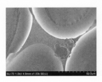
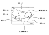
- FIG. 2F is an enlarged photograph showing the state of the bubble skeleton 43 in FIG. 2B.
- FIG. 2G is a view for explaining the configuration of the bubble skeleton 43 shown in FIG. 2F.
- FIG. 2H is an enlarged photograph showing the state of the bubble skeleton 43 shown in FIG. 2F in more detail.
- FIG. 2I is a diagram for explaining the configuration of the bubble skeleton 43 shown in FIG. 2H.
- the 2nd through-hole 45 is formed in the interface of the powder 46 and the urethane resin (open cell resin) which comprises the open cell urethane foam 4. As shown in FIG.
- the second through-hole 45 passes through the bubble skeleton 43 and communicates the bubbles 47 that are separated from each other and adjacent to each other.
- the diameter and length of the second through hole 45 are larger than those of the first through hole 44.
- the second through hole 45 is formed, for example, when the non-affinity powder 46 does not adhere to the urethane resin.
- the raw material (urethane liquid) of the open-cell urethane foam 4 is a mixture of a thermosetting urethane resin component (first resin component, second resin component), a foaming agent, and powder 46.
- the first resin component is, for example, a mixture of a plurality (three in this embodiment) of polyols, and these polyols have different compositions.
- the second resin component is polyisocyanate, and for example, polymethylene polyphenyl polyisocyanate is used as the isocyanate.
- water is used as the foaming agent.
- the powder 46 is a fine powder dispersed in the open-cell urethane foam 4.
- the particle diameter of the powder 46 is smaller than the bubbles 47, for example, smaller than 1000 ⁇ m, and particularly preferably 10 to 30 ⁇ m, for example.
- the powder 46 is non-affinity with respect to the resin of the open-cell urethane foam 4, and its SP value is, for example, 9.5 or less.
- the powder 46 polyethylene (PE), nylon (Ny-12), or the like is used.
- the SP value of the urethane resin (resin of the open cell urethane foam 4) is, for example, 10 to 11. For this reason, as the difference between the SP value of the urethane resin and the SP value of the powder 46 increases, the urethane resin and the powder 46 are less likely to adhere to each other.
- the second through hole 45 is formed between the urethane resin and the powder 46.
- additives such as a foam stabilizer, a catalyst, a flame retardant, an antioxidant, a colorant, and a viscosity reducer may be added to the urethane liquid as necessary.
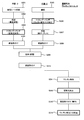
- FIG. 3 is a flowchart showing an assembly example of the refrigerator 20 shown in FIG. 1A. As FIG. 3 shows, about the heat insulation box (heat insulation housing
- the heat insulation box heat insulation housing
- a hard resin such as ABS resin is formed into a sheet (step: S301).
- the hard resin sheet is vacuum formed into a desired box-shaped inner box 3 (step: S302). Specifically, the sheet of hard resin is heated, and the sheet is pressed against the mold of the inner box 3 before the softened sheet is cooled and solidified. Then, air is evacuated from the hole of the mold, the inside of the mold is evacuated, and the sheet is brought into close contact with the mold. Thereby, a desired box shape as the inner box 3 is obtained.
- step: S303 the air holes 6 are punched into each of the locations where the air holes 6 shown in FIG. 1A are provided.
- step: S304 the predetermined
- a metal steel plate is prepared (step: S305).
- the urethane liquid injection port 5 is punched into a steel plate by a trimming punch at each of the locations where the urethane liquid injection port 5 shown in FIG. 1A is provided (step: S306).
- press-molding such as a bending process, is given with respect to the steel plate after stamping, and it shape
- the inner box 3 and the outer box 2 manufactured as described above are combined to form a wall body (step: S309).
- the flange formed at the front side of the inner box 3 is fitted into the groove formed at the front side of the outer box 2.
- the inner box 3 is attached to the outer box 2 to form a hollow wall, and this inner space is formed as a heat insulating space 10.
- a predetermined part for the refrigerator 20 to be attached before the open-cell urethane foam 4 is filled in the heat insulation space 10 is attached to the walls 2 and 3 (step S310).
- the open-cell urethane foam 4 is integrally foam-molded in the heat insulating space 10 between the outer box 2 and the inner box 3 (step S311).
- This integral foam molding will be described with reference to FIG.
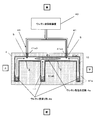
- FIG. 4 is a cross-sectional view for explaining integral foam molding of the heat insulation box 21 using the urethane foam jig 41a.
- the two urethane liquid inlets 5 in FIG. 4 represent the two upper and lower urethane liquid inlets 5 shown in FIG. 1A.
- the two urethane liquid inlets 5 are located on the rear side of the three urethane liquid reservoirs 4b.
- the urethane liquid is injected into the two upper and lower urethane liquid injection ports 5 shown in FIG. 1A in the same manner as the right urethane liquid injection port 5.
- the urethane foam jig 41a is a jig for supporting the walls 2 and 3 at the time of integral foam molding, and includes, for example, a first jig 41a1 and a second jig 41a2.
- the first jig 41a1 is provided with a recess so as to support the outer box 2 side of the wall. This recess has a shape along the rear surface of the outer box 2, that is, a shape corresponding to the rear surface of the heat insulating box body 21.
- the first jig 41a1 is provided with a perforation 41a3 at a position corresponding to the urethane liquid inlet 5 of the outer box 2 when the box is fitted in the recess.
- the second jig 41a2 is provided with a recess so as to support the inner box 3 side of the wall. This recess has a shape corresponding to the front surface of the inner box 3, that is, the front surface of the heat insulating box 21 including the partition plate 25.
- the second jig 41a2 is provided with a perforation (not shown) at a position corresponding to the air hole 6 of the inner box 3 when the box is fitted in the recess.
- the urethane liquid injection port 5 communicates with the perforation 41a3, and the air hole 6 communicates with the perforation of the second jig 41a2. For this reason, the tip of the liquid supply hose 41 of the urethane liquid supply device 40 is connected to the urethane liquid inlet 5 through the perforations 41a3. Then, the urethane liquid is injected into each of the two urethane liquid inlets 5 from the urethane liquid supply device 40 via the liquid supply hose 41.
- the amount of the urethane liquid supplied to each of the two urethane liquid inlets 5 may be the same, or may be individually adjusted so that the heat insulation space 10 is uniformly filled.
- the urethane liquid flows into the heat insulating space 10 from each of the two urethane liquid inlets 5 and flows to the three urethane liquid reservoirs 4b located on the front side of the urethane liquid inlet 5 to each urethane liquid reservoir. 4b is stored.
- the components of the urethane liquid are mixed, and the mixture of the polyol of the first resin component and the polyisocyanate of the second resin component are polymerized to form a thermosetting urethane resin.
- the foaming agent is vaporized by heat generated by the polymerization reaction, and bubbles 47 are formed in the urethane resin. Further, distortion at a molecular level is caused by a plurality of polyols having different compositions, and as shown in FIGS.
- a second through hole 45 is formed between the thermosetting urethane resin and the powder body 46, and the second through hole 45 penetrates the bubble skeleton 43. In this way, open-cell urethane foam 4 is formed.
- the open-cell urethane foam 4 expands while pushing away the air existing in the heat insulation space 10 from each urethane liquid reservoir 4 b toward the urethane liquid inlet 5. , Solidify. And the open-cell urethane foam 4 goes to the back side from each of the three urethane liquid reservoirs 4b, joins at the urethane foam joint 4a, and is uniformly filled into the heat insulating space 10. Further, the pushed air joins at the urethane foam joining portion 4a, and is exhausted from the urethane foam joining portion 4a through the air hole 6 (FIG. 1A). For this reason, at the time of filling with the open cell urethane foam 4, the generation of an air reservoir in the heat insulating space 10 is prevented, and the formation of the unfilled portion of the open cell urethane foam 4 is suppressed.
- step S312 the molded product in which the open-cell urethane foam 4 is filled in the heat insulation space 10 is taken out from the urethane foam jig 41a, and the air holes 6 in the inner box 3 of the wall are sealed as shown in FIG. Stop (step S312). And the remaining components for the refrigerator 20 are attached to the walls 2 and 3 in the refrigerator 20 (step S313). Then, each urethane liquid inlet 5 in the outer box 2 of the wall is sealed (step S314). Thereby, the refrigerator 20 is manufactured.
- the timing for fixing the inner box 3 and the outer box 2 is not particularly limited.
- the inner box 3 and the outer box 2 may be fixed with a fixing member or an adhesive.
- the urethane liquid injection port 5 is sealed (step S314), the inner box 3 and the outer box 2 may be fixed.
- FIG. 5A is a diagram illustrating a sealing example 1 of the air hole 6 of the refrigerator 20.
- FIG. 5B is a partial cross-sectional view showing a part of the refrigerator 20 cut along the line BB shown in FIG. 5A.
- an adhesive such as an epoxy resin is individually applied around the 40 air holes 6 of the inner box 3 one by one.
- a disk-shaped air hole sealing material 60 formed of an air impermeable material such as silicon rubber or butyl rubber is attached on each air hole 6 to seal each air hole 6.
- the air hole sealing material 60 does not have to cover the area other than the air holes 6 in the inner box 3. For this reason, the area of the air hole sealing material 60 is small, and the cost can be reduced. Moreover, even if there is an air hole 6 that is insufficiently sealed, the sealing of other air holes 6 is not affected by this. Therefore, a decrease in hermeticity can be suppressed.
- FIG. 6A is a diagram illustrating a sealing example 2 of the air hole 6 of the refrigerator 20.
- FIG. 6B is a partial cross-sectional view showing a part of refrigerator 20 cut along the line CC shown in FIG. 6A.
- the air hole sealing material 61 (sealing material) is pasted together on the 30 air holes 6 on the refrigerator compartment 26 side of the inner box 3, and these air holes 6 are attached. Is sealed. Further, another air hole sealing material 61 is attached to the 10 air holes 6 on the freezer compartment 27 side of the inner box 3 to seal these air holes 6.
- Each of these two air hole sealing materials 61 is in the form of a sheet, and is formed of an air impermeable material such as silicon rubber or butyl rubber (isobutylene isoprene rubber).
- the sealing work can be reduced.
- the remaining components for the refrigerator 20 can be quickly attached.
- FIG. 7A is a diagram illustrating a sealing example 3 of the air hole 6 of the refrigerator 20.
- FIG. 7B is a partial sectional view showing a part of the refrigerator 20 cut along the line DD shown in FIG. 7A.
- the air hole sealing material 62 (sealing material) is mechanically embedded one by one in each of the 40 air holes 6 in the inner box 3, and each air hole 6 is It is sealed.
- the air hole sealing material 62 has a screw shape (including a bolt) and has a cylindrical portion and a head portion.
- the cylindrical portion has substantially the same diameter and length as the air hole 6 and fits into the air hole 6.
- the head has a disk shape and the diameter is larger than the air hole 6. For this reason, when the cylindrical part of the air hole sealing material 62 is fitted into the air hole 6, the head covers the gap between the air hole 6 and the cylindrical part.
- the air hole sealing material 62 does not have to cover the area other than the air holes 6 in the inner box 3. For this reason, the size of the air hole sealing material 62 is small, and the cost can be reduced. Moreover, even if there is an air hole 6 that is insufficiently sealed, the sealing of other air holes 6 is not affected by this. Therefore, a decrease in hermeticity can be suppressed. Moreover, since the air hole sealing material 62 is mechanically embedded in the air holes 6, no waiting time such as resin curing after bonding is required, and the remaining parts for the refrigerator 20 after the air holes 6 are sealed. Can be quickly installed.
- FIG. 8A is a diagram showing a sealing example 1 of the urethane liquid inlet 5 of the refrigerator 20.
- FIG. 8B is a partial cross-sectional view showing a part of the refrigerator 20 cut along the line EE shown in FIG. 8A.
- the urethane liquid injection port sealing material 50 (sealing material) is individually attached to the four urethane liquid injection ports 5 one by one with an adhesive or the like.
- the urethane liquid inlet sealing material 50 has a sheet shape and is formed of an air impermeable material such as silicon rubber, butyl rubber, or an iron plate.
- FIG. 9A is a diagram illustrating a sealing example 2 of the urethane liquid inlet 5 of the refrigerator 20.
- FIG. 9B is a partial cross-sectional view showing a part of the refrigerator 20 cut along the line FF shown in FIG. 9A.
- the four urethane liquid injection ports 5 are individually covered and sealed with a urethane liquid injection port sealing material 51 (sealing material) one by one.
- the urethane liquid inlet sealing material 51 has, for example, a disk shape and is formed of an air impermeable material such as silicon rubber, butyl rubber, or iron plate.
- four first fixing holes are formed on the outer peripheral side of the urethane liquid inlet sealing material 51.
- the outer box 2 is also provided with, for example, four second fixing holes on the outer periphery of the urethane liquid inlet 5. Therefore, the urethane liquid inlet sealing material 51 is disposed on the urethane liquid inlet 5 so that the first fixing hole and the second fixing hole correspond to each other.
- a fixing member 52 such as a screw is inserted into the first fixing hole and the second fixing hole, and the urethane liquid inlet sealing material 51 is fixed to the outer box 2. Thereby, the urethane liquid inlet sealing material 51 can cover and seal the urethane liquid inlet 5.
- the fixing member 52 by using the fixing member 52, the urethane liquid inlet sealing material 51 can be easily and reliably fixed to the outer box 2, so that the sealing reliability can be improved.
- the air holes 6 for venting the air are provided in the walls 2 and 3, so that the fluidity of the urethane liquid and the air is ensured in the heat insulating space 10 when the urethane liquid is injected and foamed. Generation of air accumulation in the space 10 is suppressed. Thereby, it is prevented that the open-cell urethane foam 4 deteriorates by the water
- the urethane liquid inlet 5 is sealed with urethane liquid inlet sealing materials 50, 51, 55, and the air holes 6 are sealed with air hole sealing materials 60, 61, 62.
- the heat insulation space 10 filled with the open-cell urethane foam 4 is sealed, and air and moisture contained therein are prevented from entering the heat insulation space 10. Therefore, deterioration of the open-cell urethane foam 4 due to moisture is suppressed, the external appearance deformation of the heat insulation box 21 is prevented, and the heat insulation performance of the heat insulation box 21 is maintained high over a long period of time.
- the open-cell urethane foam 4 is formed by integral foaming in the sealed heat-insulating space 10 as in the prior art, the skin layer 4d having a high density and a large number of closed cells cannot be avoided.
- the communication of the skin layer 4d is neither disclosed nor suggested in the prior art.
- the bubbles 47 in the entire open-cell urethane foam 4 including the skin layer 4d can be communicated.
- the first through-hole 44 that penetrates the cell membrane portion 42 is formed by a plurality of polyols having different compositions
- the second through-hole 45 that penetrates the cell skeleton 43 is formed by the powder 46.
- the second through-hole 45 can be formed not only in the core layer 4 c but also in the skin layer 4 d having many bubble skeletons 43 by the powder 46 having a diameter larger than the thickness of the bubble skeleton 43.
- the air bubbles 47 communicate with each other through the through holes 44 and 45 in the entire open cell urethane foam 4.
- the diameter of the air hole 6 smaller than that of the urethane liquid inlet 5, it is possible to prevent the occurrence of an air reservoir while suppressing leakage of the urethane liquid.
- the air hole 6 and the urethane liquid injection port 5 are separately formed in the inner box 3 and the outer box 2, it is possible to efficiently prevent the occurrence of an air reservoir due to the air hole 6.
- the heat insulation box 21 according to Embodiment 2 of the present invention is obtained by filling the open-cell urethane foam 4 shown in FIG. 1A into the heat insulation space 10 and then evacuating the heat insulation space 10. Thereby, the pressure of the space 10 for heat insulation becomes lower than atmospheric pressure, and the space 10 for heat insulation becomes a vacuum state.
- This vacuum state includes a state where the pressure in the heat insulation space 10 is lower than the atmospheric pressure.
- the urethane liquid injection port 5 in the first embodiment is also used as an exhaust hole (gas flow port) to which a vacuum pump for evacuation is connected.
- the structural example of the heat insulation box 21 shown to FIG. 1A and FIG. 1B is applicable to the heat insulation box 21 which concerns on Embodiment 2.
- FIG. 1A and FIG. 1B is applicable to the heat insulation box 21 which concerns on Embodiment 2.
- FIG. 10 is a flowchart illustrating an assembly example of the refrigerator 20 including the heat insulating box 21 according to the second embodiment.
- a hard resin such as an ABS resin and a metal foil are prepared (step: S1001).
- insert molding for integrating the metal foil with the hard resin is performed (step: S1002).
- the box-shaped inner box 3 in which desired airtightness is ensured is obtained.
- the air holes 6 are punched by a trimming punch at predetermined locations on the back plate of the inner box 3 (step: S1003).
- prescribed components for the refrigerator 20 which should be attached before the inner case 3 and the outer case 2 are united are attached to the inner case 3 (step: S1004).
- a urethane liquid injection port 5 serving also as an exhaust hole is punched out by a trimming punch at a predetermined location in a metal steel plate (steps: S1005, S1006). Then, press forming such as bending is performed on the steel sheet after punching (step: S1007). Thereby, the desired box shape as the outer box 2 is obtained. And the predetermined
- step: S1009 The inner box 3 and the outer box 2 produced independently as described above are combined (mounted) (step: S1009). Since this specific mounting method is the same as that of Embodiment 1, the description thereof is omitted. And the predetermined
- the open-cell urethane foam 4 is integrally foam-molded in the heat insulating space 10 between the outer box 2 and the inner box 3 (step S1011).
- This integral foam molding is as described above with reference to FIG. Thereby, since the air merged into the urethane liquid reservoir 4b is exhausted from the air hole 6 (see FIG. 1A) on the back surface of the inner box 3, the air reservoir (unfilled with urethane) is used in the heat insulation space 10 of the heat insulation box 21. Part) is suppressed.
- step S1012 40 air holes 6 in the inner box 3 are sealed (step S1012). Then, a vacuum pump is connected to the urethane liquid injection port 5 also serving as an exhaust hole, and the heat insulating space 10 filled with the open-cell urethane foam 4 is exhausted. Thereby, after the space 10 for heat insulation is pressure-reduced, the remaining components for the refrigerator 20 are attached to the wall bodies 2 and 3 (step S1013).
- the urethane liquid injection port 5 also serving as an exhaust hole is sealed (step S1014).
- the sealing example of the urethane liquid injection port 5 also serving as the exhaust hole is the same as in the first embodiment, and the urethane liquid injection port sealing materials 50 and 51 can be used.
- the sealing examples shown in FIGS. 11A and 11B may be employed.
- FIG. 11A is a diagram showing a sealing example of the urethane liquid injection port 5 also serving as an exhaust hole.
- FIG. 11B is a partial cross-sectional view showing a part of refrigerator 20 cut along the line GG shown in FIG. 11A.
- the urethane liquid injection port sealing material 55 is formed of an air-impermeable material such as silicon rubber, butyl rubber, or iron plate, and has a flat surface portion 56, a pinch portion 57, and an exhaust hole 58. Yes.
- the flat portion 56 has a circular shape having a diameter larger than the hole diameter of the urethane liquid injection port 5 serving also as an exhaust hole, and is disposed on the urethane liquid injection port 5.
- the exhaust hole 58 is disposed at the center of the flat part 56 and has a hole diameter equal to or smaller than the hole diameter of the urethane liquid inlet 5.
- the pinch portion 57 stands upright in a cylindrical shape from the exhaust hole 58, and its tip can be sealed.
- the hole diameter of the exhaust hole 58 is determined so that a reduction in time required for exhaustion and ease of pinch can be realized in a balanced manner. For example, if the hole diameter of the exhaust hole 58 is small, the time required for exhaust becomes longer, but sealing with the pinch portion 57 becomes easier. On the other hand, if the hole diameter of the exhaust hole 58 is large, sealing with the pinch portion 57 is difficult, but the time required for exhaust can be shortened. In the present embodiment, for example, 10 mm can be employed. In addition, when the hole diameter of the exhaust hole 58 is small, it may not be sealed by the pinch part 57, for example, you may seal the exhaust hole 58 using sealing materials, such as resin and glass.
- the heat insulating property of the heat insulating box 21 in which the open-cell urethane foam 4 is filled in the heat insulating space 10 can be maintained high by sealing the exhaust hole 58.
- the exhaust hole 58 can be sealed at the same time as the urethane liquid inlet 5 is sealed. Thereby, the assembly man-hour of the heat insulation box 21 and the cold insulation apparatus (for example, refrigerator) provided with this can be reduced.
- an exhaust hole may be provided independently of the urethane liquid inlet 5.
- the sealing example of the urethane liquid inlet 5 in the first embodiment can be applied.
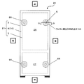
- FIG. 12 is a front view of the refrigerator 20 including the heat insulation box 21 according to Embodiment 3 of the present invention.
- one gas adsorption device 85 is arranged in each of the heat insulation spaces 10 on both side surfaces of the freezer compartment 27 on the lower left side and the lower right side of the heat insulation box 21 shown in FIG. Thereby, since the cooling holding temperature of the freezer compartment 27 is lower than that of the refrigerator compartment 26, the gas in the heat insulation space 10 moves into the heat insulation space around the freezer compartment 27 and is efficiently adsorbed by the gas adsorption device 85. obtain.
- the arrangement and number of the gas adsorption devices 85 can be changed according to the size and form of the refrigerator 20, and the number and arrangement of the two places are not limited thereto.
- FIG. 13 is an example of a cross-sectional view of the gas adsorption device 85.
- the gas adsorbing device 85 includes a gas adsorbing substance 86 and a storage container 87 having an opening 88 for storing the gas adsorbing substance 86.
- the gas adsorbing substance 86 plays a role of adsorbing gas such as water vapor, air, carbon dioxide gas remaining or entering the sealed space.
- the gas adsorbing substance 86 is not particularly specified, but a chemical adsorbing substance such as calcium oxide and magnesium oxide, a physical adsorbing substance such as zeolite, or a mixture thereof can be used.
- a ZSM-5 type zeolite having both chemical adsorption properties and physical adsorption properties and subjected to copper ion exchange can be used as the gas adsorbing material 86. Since this ZSM-5 type zeolite has a particularly high nitrogen adsorption capacity under a low pressure lower than the atmospheric pressure, it is possible to strongly adsorb nitrogen during the mixing of air.
- an adsorbent that adsorbs carbon dioxide gas for example, ZSM-5 zeolite ion-exchanged with barium and / or strontium, can also be used as the gas adsorbing material 86.
- the gas adsorbing substance 86 that adsorbs the carbon dioxide gas is desirably a material obtained by ion-exchange of barium and / or strontium with ZSM-5 type zeolite as a main component.
- the amount of carbon dioxide adsorption of Na-A type zeolite, which is one of the prior arts, is 3 cc / g under 10 Pa.
- barium ion exchanged ZSM-5 type zeolite has a carbon dioxide adsorption of 12 cc / g under 10 Pa, and can adsorb and remove a large volume of dilute carbon dioxide. Thereby, it is possible to maintain the vacuum degree of the heat insulation space 10 in which the gas adsorption device 85 is arranged high.
- the zeolite ion-exchanged with barium and / or strontium as described above is a carbon dioxide adsorbent containing a ZSM-5 type zeolite containing barium (Ba) and / or strontium (Sr), and is a ZSM-5 type zeolite Includes Ba—O—Ba species and / or Sr—O—Sr species.
- Ba—O—Ba species and / or Sr—O—Sr species As a result, a strong interaction with carbon dioxide occurs, so that carbon dioxide is strongly adsorbed even under conditions where the equilibrium pressure is lower than atmospheric pressure and the carbon dioxide is dilute, and large-capacity adsorption of carbon dioxide becomes possible.
- the storage container 87 has a property that it is difficult for gas such as air and water vapor to pass through, and plays a role of preventing the gas adsorbing material 86 from coming into contact with the gas before the gas adsorbing device 85 is used.
- the material and shape of the storage container 87 are not particularly specified.
- As the material of the storage container 87 for example, a metal material such as aluminum, copper, iron, and stainless steel is used.
- the shape of the storage container 87 is formed in, for example, an elongated flat cylindrical shape.
- the assembling example of the refrigerator 20 according to Embodiment 3 is substantially the same as the assembling example of the refrigerator 20 shown in the flowchart of FIG.
- the plurality of gas adsorption devices 85 are dispersed and arranged in the heat insulation space 10 in the walls 2 and 3.
- the urethane liquid of the open-cell urethane foam 4 is inject
- the air holes 6 are sealed with air hole sealing materials 60, 61, 65 and the like.
- the inside of the heat insulating space 10 is evacuated from the urethane liquid inlet 5 also serving as an exhaust hole, and the urethane liquid inlet 5 also serving as an exhaust hole is sealed with a urethane liquid inlet sealing material 50, 51, 55 or the like. .
- the time for evacuating the heat insulation space 10 can be shortened.
- the vacuum flow can be sufficiently exhausted during the pressure of the viscous flow (low vacuum), but the exhaust resistance increases in the vacuum range (high vacuum) of the molecular flow. Exhaust takes time. Therefore, the gas adsorption devices 85 are distributed in advance in the heat insulation space 10 so that the gas adsorption devices 85 exhibit a gas adsorption function. Thereby, the exhaust distance of the open-cell urethane foam 4 becomes short, and the heat insulation space 10 can be efficiently decompressed (evacuated).
- the gas adsorption device 85 adsorbs the trace gas remaining after the inside of the heat insulation space 10 of the heat insulation box 21 is evacuated, the heat insulation space 10 can be maintained at a desired degree of vacuum.
- the trace gas remaining in the heat insulating space 10 includes carbon dioxide gas generated by the reaction of water and isocyanate in addition to the air component.
- the gas adsorption devices 85 that adsorb carbon dioxide gas may be dispersedly arranged in the heat insulation space 10.
- the gas adsorption devices 86 may be dispersedly arranged in the heat insulation box 21 or the heat insulation space 10 of the heat insulation wall according to the first embodiment that is not evacuated. By exhibiting the gas adsorption function of the gas adsorption device, it becomes easier to prevent the open-cell urethane foam 4 from being deteriorated in the heat insulation space 10.
- the heat insulating box body 21 according to the fourth embodiment of the present invention is formed by molding the open-cell urethane foam 4 by integral foaming using a part of the wall body as a skin material, and attaching the remaining wall body to this molded body. Is done.
- a part of the wall body is described as the inner box 3 and the remaining wall body is described as the outer box 2.
- the description is omitted because they are the same when they are replaced.
- FIG. 14 is a cross-sectional view for explaining the integral foam molding of the heat insulating box 21. Except for the first jig 41a1, the urethane foam jig 41a shown in FIG. 14 is the same as the urethane foam jig 41a shown in FIG.
- the urethane foam jig 41a described in the present embodiment supports the wall body 3 during integral foam molding and functions as a mold for molding the open-cell urethane foam 4. That is, the second jig 41a2 supports the inner box 3 by fitting the inner box 3 in the recess.
- the outer box 2 is not fitted in the recess provided in the first jig 41a1, and the recess has a shape along the front surface of the outer box 2, and the mold on the rear surface side of the heat insulating box 21 is provided.
- the air pushed away from the heat insulating space 10 at the time of injecting the urethane liquid and foaming may be discharged from the gap between the first jig 41a1 and the second jig 41a2.
- the air hole 6 of the inner box 3 and the perforation of the second jig 41a2 arranged corresponding to this may not be provided.
- the inner box 3 When integral foaming is performed using the urethane foam jig 41a, first, as shown in FIG. 14, the inner box 3 is fitted into the recess of the second jig 41a2, and then the first jig 41a1 is moved to the second jig. It arranges on 41a2. Thereby, an internal space surrounded by the front surface of the recess of the first jig 41a1 and the rear surface of the inner box 3 is formed. This internal space has the same shape as the heat insulating space 10 surrounded by the front surface of the outer box 2 and the rear surface of the inner box 3.
- the tip of the liquid supply hose 41 of the urethane liquid supply device 40 is connected to the urethane liquid injection port 5, and the urethane liquid is injected from the urethane liquid supply device 40 to the urethane liquid injection port 5 via the liquid supply hose 41.
- the urethane liquid is integrally foamed with the inner box 3 to form a molded body using the inner box 3 as a skin material of the open-cell urethane foam 4.
- the open cell urethane foam 4 has a shape corresponding to the space 10 for heat insulation.
- the front surface of the open-cell urethane foam 4 is covered with the inner box 3, but the rear surface is exposed.
- the molded body is taken out from the urethane foam jig 41 a and the rear surface of the open cell urethane foam 4 is covered with the outer box 2.
- the whole open-cell urethane foam 4 is coat
- the heat insulating space 10 surrounded by the inner box 3 and the outer box 2 is in a vacuum state. It may be.
- the exhaust hole is provided in the inner box 3 and / or the outer box 2, after exhausting from the exhaust hole and evacuating the heat insulation space 10, the exhaust hole is sealed with an exhaust hole sealing material. Stop.
- the gas adsorption device is placed in the heat insulating space 10 surrounded by the inner box 3 and the outer box 2.
- 85 may be arranged.
- the outer box 2 may be attached to the molded product.
- the rear surface of the open cell urethane foam 4 is exposed.
- the skin layer corresponding to the exhaust hole or the urethane liquid injection port 5 also serving as the exhaust hole can be cut off.
- the part with many bubbles 47 and each through-holes 44 and 45 in open-cell urethane foam 4 is exposed.
- a vacuum pump is connected to this portion, the air in the open-cell urethane foam 4 can be smoothly discharged through the bubbles 47 and the through holes 44 and 45.
- an air hole 6 can be provided in the inner box 3.
- a perforation of the second jig 41a2 disposed corresponding to the air hole 6 is provided.
- the molded product may be covered with the inner box 3.
- a urethane liquid injection port 5 is provided in the outer box 2
- a hole 41 a 3 is provided at the position of the first jig 41 a 1 corresponding to the urethane liquid injection port 5.
- the urethane liquid inlet 5 is sealed with a urethane liquid inlet sealing material to form the heat insulating box 21. Is done.
- the heat insulating box 21 is manufactured by mounting the remaining outer box 2 on the molded body.
- the deformation of the box body 21 can be reduced.
- the thermal expansion coefficient of the outer box 2 is different from the thermal expansion coefficient of the inner box 3 and the open cell urethane foam 4. .
- the dimensional change of the inner case 3 and the open cell urethane foam 4 is larger than that of the outer case 2 due to heat generated when the urethane liquid undergoes a polymerization reaction.
- the heat insulating box 21 in which the open cell urethane foam 4 is filled in the heat insulating space 10 between them may be deformed.
- the inner box 3 and the urethane liquid of the open cell urethane foam 4 are formed by integral foaming. Therefore, since the thermal expansion coefficients of the inner box 3 and the open-cell urethane foam 4 are close to each other, the molded body is not easily deformed by both being thermally expanded to the same extent and then being cooled and contracted. If the outer casing 2 having a coefficient of thermal expansion different from that of the open-cell urethane foam 4 is attached to the molded body to form the heat insulating box 21, the dimensional deformation of the heat insulating box 21 can be prevented.
- the heat insulating box 21 which is a box-shaped container having an internal space and having an open front has been described as an example of a heat insulating wall.
- the shape of the heat insulating wall is not limited to this. That is, the heat insulating wall includes a wall body that functions as a skin material, and an open-cell resin body of a thermosetting resin that is integrally formed with at least a part of the wall body and functions as a heat insulating material. Good.
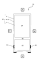
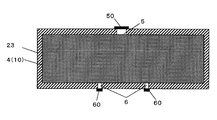
- the open-cell urethane foam 4 may be filled into the heat insulation space 10 of the substantially flat wall 23 to form a substantially flat heat insulating wall.
- This heat insulation wall is used for the door of the refrigerator 20 and the door of a house, for example.
- the wall body 23 is composed of one hollow container, and the internal space is used as the heat insulation space 10.
- the heat insulating box 21 is used for the frame of the refrigerator 20, but the use of the heat insulating box 21 is not limited to this.
- the heat insulating box 21 can be used in a pot, a portable cool box casing, a thermostatic bath casing, a hot water storage casing, a cooler box, and the like shown in FIG.
- the outer box 2 and the inner box 3 each have a cylindrical shape having a bottom, and the inner box 3 is housed in the outer box 2.
- An open cell urethane foam 4 is filled in the heat insulating space 10 between the outer box 2 and the inner box 3 by integral foaming.
- the urethane liquid inlet 5 penetrating the outer box 2 is sealed with a urethane liquid inlet sealing material 50, and the air holes 6 penetrating the inner box 3 are sealed with an air hole sealing material 60.
- the open cell resin body is the open cell urethane foam 4, and a thermosetting urethane resin is used as the resin constituting the open cell resin body.
- the open cell resin body and the constituent resin thereof are not limited to this as long as the constituent resin is a thermosetting resin.
- the open cell resin body may be an open cell phenol foam, and a thermosetting phenol resin may be used as the constituent resin.
- the raw material of this phenol resin is a phenol resin component (for example, phenol and formaldehyde), a foaming agent, and a powder. A second through hole is formed in the bubble skeleton of the phenol resin by the powder.
- a foam breaker for example, calcium stearate
- a foam breaker that ruptures the bubble film portion 42 can be blended in the urethane liquid.
- the heat insulation box of the present invention is designed to save energy by improving the heat insulation performance while increasing the internal volume, such as refrigerators, vending machines, hot water supply containers, heat insulation materials for buildings, heat insulation materials for automobiles, cold insulation / heat insulation. It can be applied to uses such as boxes.
Landscapes
- Engineering & Computer Science (AREA)
- Chemical & Material Sciences (AREA)
- General Engineering & Computer Science (AREA)
- Mechanical Engineering (AREA)
- Combustion & Propulsion (AREA)
- Physics & Mathematics (AREA)
- Thermal Sciences (AREA)
- Materials Engineering (AREA)
- General Chemical & Material Sciences (AREA)
- Health & Medical Sciences (AREA)
- Chemical Kinetics & Catalysis (AREA)
- Medicinal Chemistry (AREA)
- Polymers & Plastics (AREA)
- Organic Chemistry (AREA)
- Refrigerator Housings (AREA)
- Thermal Insulation (AREA)
- Polyurethanes Or Polyureas (AREA)
Abstract
Description
本発明は、断熱壁、断熱箱体およびその製造方法に関する。 The present invention relates to a heat insulating wall, a heat insulating box, and a manufacturing method thereof.
近年、地球環境問題である温暖化の対策として省エネルギー化を推進する動きが活発している。特許文献1には、断熱箱体のブロー成形用のエアー送入口から「連続気泡ウレタンフォーム」を断熱箱体の断熱用空間に充填発泡した後、該エアー送入口に接続した真空排気装置により断熱箱体内を排気して真空にする技術が提案されている。なお、連続気泡とは、各々の気泡が連通している構造のことをいう。これに対し、独立気泡とは、各々の気泡が独立して非連通である構造のことをいう。
In recent years, there has been an active movement to promote energy conservation as a countermeasure against global warming, which is a global environmental problem. In
本発明者は、下記の着眼点から、上述の従来技術は下記のような課題を有することを見出した。すなわち、上記従来の発明には、連続気泡ウレタンフォームを断熱用空間に均一に充填する方法が示されていない。このため、従来の発明では、不均一に充填された連続気泡ウレタンフォーム、および、連続気泡ウレタンフォーム内の独立気泡から放出されるガスによって、断熱箱体の外観が変形するという課題がある。 The present inventor has found that the above-described prior art has the following problems from the following viewpoints. That is, the above-described conventional invention does not show a method for uniformly filling the space for heat insulation with open-cell urethane foam. For this reason, in the conventional invention, there exists a subject that the external appearance of a heat insulation box body deform | transforms by the gas discharge | released from the closed cell in the open cell urethane foam and the open cell urethane foam which were filled nonuniformly.
また、従来の発明には、連続気泡ウレタンフォームが断熱用空間に充填された後に、断熱用空間へ水分が侵入することを防ぐ方法が開示されていない。このため、従来の発明では、侵入した水分によって連続気泡ウレタンフォームが劣化し、断熱箱体の断熱性能が低下するという課題がある。 Further, the conventional invention does not disclose a method for preventing moisture from entering the space for heat insulation after the open-cell urethane foam is filled in the space for heat insulation. For this reason, in the conventional invention, there is a problem that the open-cell urethane foam is deteriorated by the invading moisture, and the heat insulation performance of the heat insulation box is lowered.
本発明は、このような課題を解決するためになされたものである。その目的は、外観変形および断熱性能の低下を抑制することができる断熱壁、断熱箱体およびその製造方法を提供することである。 The present invention has been made to solve such problems. The purpose is to provide a heat insulating wall, a heat insulating box, and a method for manufacturing the same, which can suppress external deformation and deterioration of heat insulating performance.
前記課題を達成するために、本発明のある形態に係る断熱壁は、中空部が断熱用空間である壁体と、前記壁体に配設され、かつ、前記断熱用空間を外部に連通する気体流通口と、前記断熱用空間に一体発泡により充填され、かつ、熱硬化性ウレタン樹脂の連続気泡ウレタンフォームと、前記気体流通口を封止する封止材と、を備える。 In order to achieve the above object, a heat insulating wall according to an embodiment of the present invention includes a wall whose hollow portion is a space for heat insulation, and the heat insulating wall that is disposed in the wall and communicates the heat insulating space to the outside. A gas flow port, an open-cell urethane foam of a thermosetting urethane resin that is filled in the heat insulation space by integral foaming, and a sealing material that seals the gas flow port.
本発明によれば、外観変形および断熱性能の低下を抑制することができる断熱壁、断熱箱体およびその製造方法を提供することができる。 According to the present invention, it is possible to provide a heat insulating wall, a heat insulating box, and a manufacturing method thereof that can suppress external deformation and deterioration of heat insulating performance.
本発明の前記目的、他の目的、特徴、および利点は、添付図面参照の下、以下の好適な実施態様の詳細な説明から明らかにされる。 The above object, other objects, features, and advantages of the present invention will become apparent from the following detailed description of preferred embodiments with reference to the accompanying drawings.
第1の本発明に係る断熱壁は、中空部が断熱用空間である壁体と、前記壁体に配設され、かつ、前記断熱用空間を外部に連通する気体流通口と、前記断熱用空間に一体発泡により充填され、かつ、熱硬化性ウレタン樹脂の連続気泡ウレタンフォームと、前記気体流通口を封止する封止材と、を備える。 The heat insulating wall according to the first aspect of the present invention includes a wall body in which a hollow portion is a space for heat insulation, a gas flow port disposed in the wall body and communicating with the space for heat insulation to the outside, and the heat insulating wall The space is filled with integral foam, and includes an open-cell urethane foam of a thermosetting urethane resin, and a sealing material that seals the gas circulation port.
ここで、「気体流通口」とは、それぞれ後述のウレタン液注入口、空気孔および排気孔の少なくともいずれか1つを含み、以下の気体流通口の記載も同様である。また、「封止材」とは、それぞれ後述の空気孔封止材、ウレタン液注入口封止材、および排気孔封止材の少なくともいずれか1つを含み、以下の封止材の記載も同様である。 Here, the “gas flow port” includes at least one of a urethane liquid injection port, an air hole, and an exhaust hole, which will be described later, and the following description of the gas flow port is the same. In addition, the “sealing material” includes at least one of an air hole sealing material, a urethane liquid inlet sealing material, and an exhaust hole sealing material, which will be described later. It is the same.
本発明によれば、断熱用空間を外部に連通する気体流通口は、連続気泡ウレタンフォームの原料を注入する際の注入口、および、断熱用空間の空気の排出口として用いられ得る。これにより、原料注入時および発泡時における断熱用空間の空気の流動性が確保されるため、連続気泡ウレタンフォームは断熱用空間に均一に充填されている。また、外部から空気が侵入する気体流通口が封止材により封止されているため、気体流通口からの水分の侵入が防がれ、水分による連続気泡ウレタンフォームの劣化が防がれている。さらに、連続気泡ウレタンフォーム内の気泡は連続的に連通化している。これらによって、断熱壁の外観変形を防ぐことができ、また、断熱性能の向上を図ることができる。 According to the present invention, the gas circulation port communicating with the heat insulation space to the outside can be used as an injection port for injecting the raw material of the open cell urethane foam and an air discharge port of the heat insulation space. Thereby, the fluidity of the air in the space for heat insulation at the time of raw material injection and foaming is ensured, so that the open cell urethane foam is uniformly filled in the space for heat insulation. In addition, since the gas flow port through which air enters from the outside is sealed with a sealing material, the intrusion of moisture from the gas flow port is prevented, and deterioration of the open-cell urethane foam due to moisture is prevented. . Furthermore, the bubbles in the open cell urethane foam are continuously communicated. By these, the external appearance deformation | transformation of a heat insulation wall can be prevented and the improvement of heat insulation performance can be aimed at.
第2の本発明に係る断熱壁は、第1の本発明において、前記連続気泡ウレタンフォームは、コア層と、前記壁体との界面近傍に形成され、かつ、当該コア層を取り囲むスキン層と、を有し、前記コア層および前記スキン層のそれぞれは、複数の気泡と、前記気泡が隣接する箇所に形成された気泡膜部と、前記気泡が隣接する箇所に形成されるとともに、隣接する前記気泡の間の距離が前記気泡膜部の厚みより大きく形成された気泡骨格部と、前記気泡膜部を貫通するように形成された第1貫通孔と、前記気泡骨格部を貫通するように形成された第2貫通孔と、を含み、前記スキン層は、前記コア層よりも多くの前記気泡骨格部を含み、前記複数の気泡が前記第1貫通孔および前記第2貫通孔により連通していてもよい。 A heat insulating wall according to a second aspect of the present invention is the heat insulating wall according to the first aspect, wherein the open-cell urethane foam is formed in the vicinity of the interface between the core layer and the wall body and surrounds the core layer. Each of the core layer and the skin layer has a plurality of bubbles, a bubble film portion formed at a location where the bubbles are adjacent to each other, and a location where the bubbles are adjacent to each other. A bubble skeleton part formed so that a distance between the bubbles is larger than a thickness of the bubble film part, a first through hole formed so as to penetrate the bubble film part, and a bubble skeleton part The skin layer includes more of the bubble skeleton than the core layer, and the plurality of bubbles communicate with each other through the first through hole and the second through hole. It may be.
これによって、コア層のみならず、気泡骨格部を多く含むスキン層においても第1貫通孔および/または第2貫通孔により気泡が連通している。これにより、断熱壁の外観変形および断熱性低下を防ぐことができる。 Thereby, not only the core layer but also the skin layer including a large amount of the bubble skeleton part allows bubbles to communicate with each other through the first through hole and / or the second through hole. Thereby, the external appearance deformation | transformation and heat insulation fall of a heat insulation wall can be prevented.
第3の本発明に係る断熱箱体は、第1または第2の本発明の1つまたは複数の断熱壁により構成され、前記壁体が、外箱と、前記外箱内に収納される内箱とを有していてもよい。 A heat insulation box according to a third aspect of the present invention is constituted by one or a plurality of heat insulation walls according to the first or second aspect of the present invention, and the wall is accommodated in an outer case and the outer case. You may have a box.
第4の本発明に係る断熱箱体は、第3の本発明において、前記気体流通口は、前記断熱用空間に前記連続気泡ウレタンフォームを充填する過程で前記断熱用空間の空気を抜くための空気孔と、前記連続気泡ウレタンフォームの原料を前記断熱用空間に注入するためのウレタン液注入口と、を有し、前記封止材は、前記空気孔を封止する空気孔封止材と、前記ウレタン液注入口を封止するウレタン液注入口封止材と、を有していてもよい。 A heat insulation box according to a fourth aspect of the present invention is the heat insulation box according to the third aspect of the present invention, wherein the gas circulation port is used for venting air in the heat insulation space in the process of filling the heat insulation space with the open cell urethane foam. An air hole and a urethane liquid injection port for injecting the raw material of the open-cell urethane foam into the heat insulation space, and the sealing material includes an air hole sealing material for sealing the air hole; And a urethane liquid inlet sealing material for sealing the urethane liquid inlet.
これによって、ウレタン液注入口から断熱用空間に連続気泡ウレタンフォームの原料を注入した際、や、原料が発泡して連続気泡ウレタンフォームが形成される際に、断熱用空間内の空気が空気孔から排出される。このため、断熱用空間に空気溜まりが形成されず、断熱用空間の全体に連続気泡ウレタンフォームを充填することができる。これにより、連続気泡ウレタンフォームの形成後において断熱箱体の外観変形の防止および断熱性能の向上を行うことができる。 As a result, when the raw material of the open cell urethane foam is injected from the urethane liquid injection port into the heat insulation space, or when the raw material is foamed to form the open cell urethane foam, the air in the heat insulation space becomes air holes. Discharged from. For this reason, an air pocket is not formed in the space for heat insulation, but the whole space for heat insulation can be filled with open-cell urethane foam. Thereby, after formation of open-cell urethane foam, the external appearance deformation | transformation of a heat insulation box can be prevented and the heat insulation performance can be improved.
また、ウレタン液注入口および空気孔を封止することにより、断熱用空間への空気や水分などの侵入を防ぐことができる。この結果、断熱箱体の外観変形を防止し、かつ、断熱性能の低下を抑制することができる。 Also, by sealing the urethane liquid injection port and the air hole, it is possible to prevent the entry of air, moisture, etc. into the space for heat insulation. As a result, it is possible to prevent external appearance deformation of the heat insulating box and to suppress a decrease in heat insulating performance.
第5の本発明に係る断熱箱体は、第4の本発明において、前記空気孔の孔径は前記ウレタン液注入口の孔径よりも小さくてもよい。 In the heat insulation box according to the fifth aspect of the present invention, in the fourth aspect of the present invention, the hole diameter of the air hole may be smaller than the hole diameter of the urethane liquid inlet.
これによって、連続気泡ウレタンフォームの原料が空気孔から漏れることを抑制することができる。 This can suppress the raw material of the open-cell urethane foam from leaking from the air holes.
第6の本発明に係る断熱箱体は、第4または第5の本発明において、前記空気孔は前記内箱に設けられ、前記ウレタン液注入口は前記外箱に設けられていてもよい。 In the heat insulation box according to the sixth aspect of the present invention, in the fourth or fifth aspect of the present invention, the air hole may be provided in the inner box, and the urethane liquid inlet may be provided in the outer box.
これによって、連続気泡ウレタンフォームの原料および空気などの流動性を確保するように、空気孔およびウレタン液注入口がそれぞれ内箱と外箱とに分離して配置することができる。 This allows the air hole and the urethane liquid inlet to be separated into the inner box and the outer box, respectively, so as to ensure the fluidity of the raw material of the open cell urethane foam and air.
第7の本発明に係る断熱箱体は、第4~第6の本発明いずれか1つにおいて、前記気体流通口は、前記断熱用空間を真空引きするための排気孔をさらに有し、前記封止材は、前記排気孔を封止する排気孔封止材をさらに有していてもよい。 In the heat insulation box according to the seventh aspect of the present invention, in any one of the fourth to sixth aspects of the present invention, the gas circulation port further includes an exhaust hole for evacuating the heat insulation space, The sealing material may further include an exhaust hole sealing material that seals the exhaust holes.
これによって、連続気泡ウレタンフォームが充填された断熱用空間を排気孔を介して真空引きすることで、断熱用空間を真空断熱層化し、さらに断熱箱体の断熱性を向上させることができる。また、空気孔およびウレタン液注入口とともに排気孔が封止されることで、断熱用空間の真空度を維持し、断熱箱体の断熱性の低下を抑制することができる。 Thus, the space for heat insulation filled with the open-cell urethane foam is evacuated through the exhaust hole, whereby the space for heat insulation is formed into a vacuum heat insulation layer, and the heat insulation property of the heat insulation box can be improved. Moreover, since the exhaust hole is sealed together with the air hole and the urethane liquid inlet, the degree of vacuum of the heat insulating space can be maintained, and a decrease in the heat insulating property of the heat insulating box can be suppressed.
第8の本発明に係る断熱箱体は、第7の本発明において、前記ウレタン液注入口は前記排気孔としても使用されていてもよい。 In the heat insulation box according to the eighth aspect of the present invention, in the seventh aspect of the present invention, the urethane liquid inlet may be used as the exhaust hole.
これによって、ウレタン液注入口の封止と排気孔の封止とが同時に実現されるので、断熱箱体の組立て工数を削減することができる。 This makes it possible to simultaneously seal the urethane liquid inlet and the exhaust hole, thereby reducing the number of assembling steps for the heat insulating box.
第9の本発明に係る断熱箱体は、第3~第8のいずれか1つの本発明において、前記断熱用空間に配設される気体吸着デバイスをさらに備えていてもよい。 The heat insulation box according to the ninth aspect of the present invention may further include a gas adsorbing device disposed in the heat insulation space in any one of the third to eighth aspects of the present invention.
これによって、気体吸着デバイスが気体吸着機能を発揮することにより、連続気泡ウレタンフォームの劣化を防ぐことがさらに容易となる。また、連続気泡ウレタンフォームが充填された断熱用空間を真空引きする場合には、気体吸着デバイスの気体吸着機能
により、連続気泡ウレタンフォームの排気距離が短くなり、効率的な真空引きを実現することができる。また、以上のように真空引きした後に、断熱用空間内に存在する微量の残存ガスを気体吸着デバイスによって吸着することができ、断熱用空間の真空度を維持することが容易となる。
This makes it easier to prevent the open-cell urethane foam from being deteriorated by the gas adsorption device exhibiting a gas adsorption function. In addition, when evacuating the space for heat insulation filled with open-cell urethane foam, the gas adsorption function of the gas adsorption device shortens the exhaust distance of the open-cell urethane foam and realizes efficient vacuuming. Can do. Moreover, after evacuating as described above, a small amount of residual gas existing in the heat insulation space can be adsorbed by the gas adsorption device, and the degree of vacuum of the heat insulation space can be easily maintained.
第10の本発明に係る断熱箱体は、前記気体吸着デバイスは、炭酸ガスを吸着する吸着剤を含み、前記吸着剤は、バリウムおよびストロンチウムの少なくともいずれか一方でイオン交換したZSM-5ゼオライトからなっていてもよい。 In the heat insulation box according to a tenth aspect of the present invention, the gas adsorption device includes an adsorbent that adsorbs carbon dioxide gas, and the adsorbent is made of ZSM-5 zeolite ion-exchanged with at least one of barium and strontium. It may be.
第11の本発明に係る断熱箱体の製造方法は、壁体を用いて断熱用空間を形成することと、前記断熱用空間に連続気泡ウレタンフォームの原料を注入することと、を備え、前記原料が前記壁体と一体発泡成形されて前記断熱用空間に充填された前記連続気泡ウレタンフォームは、複数の気泡と、前記気泡が隣接する箇所に形成された気泡膜部と、前記気泡が隣接する箇所に形成されるとともに、隣接する前記気泡の間の距離が前記気泡膜部の厚みより大きく形成された気泡骨格部と、前記気泡膜部を貫通するように形成された第1貫通孔と、前記気泡骨格部を貫通するように形成された第2貫通孔と、を有し、前記複数の気泡が前記第1貫通孔および前記第2貫通孔により連通され、前記原料は、前記第1貫通孔を形成するための、組成が異なる複数のポリオール混合物と、前記ポリオール混合物と重合反応して、前記気泡膜部および前記気泡骨格部を構成する熱硬化性ウレタン樹脂を生成するポリイソシアネートと、前記気泡を形成する発泡剤と、前記第2貫通孔を形成するための、前記熱硬化性樹脂とは非親和性の粉末と、を含む。 The manufacturing method of the heat insulation box which concerns on 11th this invention comprises forming the space for heat insulation using a wall, and inject | pouring the raw material of open-cell urethane foam in the said space for heat insulation, The open-cell urethane foam, in which the raw material is integrally foam-molded with the wall body and filled in the heat insulation space, has a plurality of bubbles, a bubble film portion formed at a location where the bubbles are adjacent, and the bubbles are adjacent to each other A bubble skeleton part formed at a position where the distance between adjacent bubbles is larger than the thickness of the bubble film part, and a first through hole formed so as to penetrate the bubble film part A second through hole formed so as to penetrate the bubble skeleton, wherein the plurality of bubbles communicate with each other through the first through hole and the second through hole. The composition for forming the through hole is A plurality of polyol mixtures, a polyisocyanate that undergoes a polymerization reaction with the polyol mixture to form a thermosetting urethane resin that constitutes the cell membrane and the cell skeleton, a foaming agent that forms the cells, And a non-affinity powder for forming the second through-hole.
この方法によれば、気体流通口から断熱用空間に連続気泡ウレタンフォームの原料を注入すると、断熱用空間を外部に連通する気体流通口から空気が排出される。このため、断熱用空間内に連続気泡ウレタンフォームを均一に充填することができる。 According to this method, when the raw material of the open-cell urethane foam is injected from the gas flow port into the heat insulation space, the air is discharged from the gas flow port communicating with the heat insulation space to the outside. For this reason, the open cell urethane foam can be uniformly filled in the space for heat insulation.
また、連続気泡ウレタンフォームの原料が、組成が異なる複数のポリオール混合物と、ポリイソシアネートと、発泡剤と、粉末と、を含んでいる。これにより、連続気泡ウレタンフォームにおいて、気泡、気泡膜部を貫通する第1貫通孔、および、気泡骨格部を貫通する第2貫通孔が形成される。これにより、連続気泡ウレタンフォームの全体において、気泡を連通することができる。 Further, the raw material of the open-cell urethane foam includes a plurality of polyol mixtures having different compositions, polyisocyanate, a foaming agent, and powder. Thereby, in the open cell urethane foam, the first through-hole penetrating the bubble, the bubble membrane portion, and the second through-hole penetrating the bubble skeleton portion are formed. Thereby, a bubble can be connected in the whole open-cell urethane foam.
第12の本発明に係る断熱箱体の製造方法は、第11の本発明において、前記壁体に配設され、かつ、前記断熱用空間を外部に連通する気体流通口を封止材により封止することと、をさらに備えていてもよい。 According to a twelfth aspect of the present invention, there is provided a method for manufacturing a heat insulating box, according to the eleventh aspect of the present invention, wherein a gas circulation port disposed in the wall body and communicating with the heat insulating space is sealed with a sealing material. And may stop further.
この方法によれば、気体流通口を封止すると、外部から断熱用空間に空気が侵入することを防ぐことができる。このため、断熱用空間内の連続気泡ウレタンフォームの劣化を防ぎ、断熱箱体の外観変形および断熱性の低下を抑制することができる。 According to this method, when the gas flow port is sealed, it is possible to prevent air from entering the heat insulation space from the outside. For this reason, deterioration of the open-cell urethane foam in the space for heat insulation can be prevented, and the external appearance deformation | transformation and heat insulation fall of a heat insulation box can be suppressed.
第13の本発明に係る断熱箱体の製造方法は、第12の本発明において、前記気体流通口は、前記断熱用空間に前記連続気泡ウレタンフォームを充填する過程で前記断熱用空間の空気を抜くための空気孔と、前記原料を注入するウレタン液注入口と、を有し、前記封止材は、前記空気孔を封止する空気孔封止材と、前記ウレタン液注入口を封止するウレタン液注入口封止材と、を有し、前記気体流通口を前記封止材により封止することは、前記ウレタン液注入口から前記断熱用空間に前記原料を注入した後、前記空気孔を前記空気孔封止材により封止することと、前記空気孔を封止した後、前記ウレタン液注入口を前記ウレタン液注入口封止材により封止することと、を含んでいてもよい。 According to a thirteenth aspect of the present invention, there is provided the heat insulating box manufacturing method according to the twelfth aspect of the present invention, wherein the gas flow port is configured to fill the heat insulating space with the air in the heat insulating space in the process of filling the heat insulating space with the open cell urethane foam. An air hole for extracting, and a urethane liquid injection port for injecting the raw material, and the sealing material seals the air hole sealing material for sealing the air hole and the urethane liquid injection port. And sealing the gas flow port with the sealing material after injecting the raw material from the urethane liquid injection port into the heat insulation space. Sealing the hole with the air hole sealing material and sealing the urethane liquid inlet with the urethane liquid inlet sealing material after sealing the air hole. Good.
この方法によれば、原料を注入した後で、空気孔を封止する前であれば、断熱用空間内の空気が空気孔から排出され、断熱用空間に連続気泡ウレタンフォームを均一に充填することができる。そして、空気孔の封止後にウレタン液注入口を封止すれば、断熱用空間を密閉することができ、侵入した水分により連続気体ウレタンフォームが劣化すること防がれる。 According to this method, after the raw material is injected and before the air holes are sealed, the air in the heat insulation space is discharged from the air holes, and the open cell foam is uniformly filled in the heat insulation space. be able to. And if a urethane liquid injection port is sealed after sealing an air hole, the space for heat insulation can be sealed, and it will prevent that a continuous gas urethane foam deteriorates with the penetrated water | moisture content.
第14の本発明に係る断熱箱体の製造方法は、第13の本発明において、前記気体流通口は、前記連続気泡ウレタンフォームが充填された前記断熱用空間を真空引きするための排気孔をさらに有し、前記封止材は、前記排気孔を封止する排気孔封止材をさらに有し、前記空気孔を封止した後、前記断熱用空間を前記排気孔を介して真空引きを行うことをさらに備え、前記気体流通口を前記封止材により封止することは、前記真空引きを行った後、前記排気孔を前記排気孔封止材により封止すること、をさらに含んでいてもよい。 According to a fourteenth aspect of the present invention, there is provided the heat insulating box manufacturing method according to the thirteenth aspect of the present invention, wherein the gas circulation port has an exhaust hole for evacuating the heat insulating space filled with the open cell urethane foam. The sealing material further includes an exhaust hole sealing material for sealing the exhaust hole, and after sealing the air hole, the heat insulating space is evacuated through the exhaust hole. Sealing the gas flow port with the sealing material further includes sealing the exhaust hole with the exhaust hole sealing material after performing the evacuation. May be.
この方法によれば、断熱用空間に連続気泡ウレタンフォームを充填した後に断熱用空間を排気孔から排気すると、断熱用空間の真空断熱層化を実現することができる。また、、空気孔、ウレタン液注入口および排気孔を封止すると、断熱用空間の真空度を高く維持することができる。 According to this method, when the space for heat insulation is exhausted from the exhaust hole after filling the space for heat insulation with open-cell urethane foam, it is possible to realize a vacuum heat insulation layer in the space for heat insulation. Moreover, when the air hole, the urethane liquid inlet, and the exhaust hole are sealed, the degree of vacuum of the heat insulating space can be maintained high.
第15の本発明に係る断熱箱体の製造方法は、第11~第14のいずれか1つの本発明において、前記原料を注入することの前に、前記断熱用空間に気体吸着デバイスを配設することをさらに備えていてもよい。 According to a fifteenth aspect of the present invention, there is provided a heat insulating box manufacturing method according to any one of the eleventh to fourteenth aspects, wherein a gas adsorbing device is disposed in the heat insulating space before the raw material is injected. There may be further provided.
この方法によれば、断熱用空間に気体吸着デバイスを配置してから、連続気泡ウレタンフォームの原料を断熱用空間に注入すると、連続気泡ウレタンフォームおよび気体吸着デバイスが断熱用空間に設けられる。このため、気体吸着デバイスが気体吸着機能を発揮し、連続気泡ウレタンフォームの劣化を防ぐことができる。また、連続気泡ウレタンフォームが充填された断熱用空間を真空引きする場合、気体吸着デバイスが気体を吸着することにより、連続気泡ウレタンフォームの排気距離を短くし、効率的な真空引きを実現することができる。さらに、真空引きした後に断熱用空間内に存在する微量の残存ガスを気体吸着デバイスが吸着し、断熱用空間の真空度を維持することがさらに容易となる。 According to this method, when the gas adsorbing device is disposed in the heat insulating space and the raw material of the open cell urethane foam is injected into the heat insulating space, the open cell urethane foam and the gas adsorbing device are provided in the heat insulating space. For this reason, a gas adsorption device exhibits a gas adsorption function and can prevent deterioration of open-cell urethane foam. Also, when evacuating the space for heat insulation filled with open-cell urethane foam, the gas adsorption device absorbs the gas, shortening the exhaust distance of the open-cell urethane foam and realizing efficient vacuuming Can do. Furthermore, the gas adsorption device adsorbs a small amount of residual gas present in the heat insulation space after evacuation, and it becomes easier to maintain the degree of vacuum in the heat insulation space.
以下、本発明の実施の形態を、図面を参照しながら説明する。なお、以下ではすべての図を通じて同一又は相当する要素には同一の参照符号を付して、特に言及しない場合にはその重複する説明を省略する。 Hereinafter, embodiments of the present invention will be described with reference to the drawings. In the following description, the same or corresponding elements are denoted by the same reference symbols throughout the drawings, and redundant description thereof is omitted unless otherwise specified.
(実施の形態1)
[冷蔵庫の構造例]
図1Aは、本発明の実施の形態1に係る断熱箱体21を備えた冷蔵庫20の正面図である。図1Bは、図1AのA-A線に沿って切断した冷蔵庫20の一部を示す部分断面図である。なお、図1Aおよび図1Bにおいて、冷蔵庫20の高さ方向を上下方向とし、冷蔵庫20の幅方向を左右方向とし、冷蔵庫20の厚み方向を前後方向とする。
(Embodiment 1)
[Refrigerator structure example]
FIG. 1A is a front view of a
図1Aに示されるように、冷蔵庫20は、断熱箱体21、および、断熱箱体21に装着された扉(図示せず)を備える。断熱箱体21は、正面が開口する箱形の容器であって、内部空間を有する。その内部空間は、たとえば、仕切り板25によって上側の冷蔵室26と下側の冷凍室27とに区画されている。この冷蔵室26を開閉自在に閉塞するように、片開き式又は両開き式の回転式扉(図示せず)が断熱箱体21に取り付けられている。冷凍室27を前後方向に開閉自在に閉塞するように、引出し式の扉(図示せず)が断熱箱体21に取り付けられている。また、冷蔵庫20には、圧縮器、蒸発器、凝縮器を備えた冷凍サイクル(図示せず)が取り付けられている。なお、冷蔵庫20の内部空間は、冷蔵室26と冷凍室27との区画に限らない。たとえば、冷蔵庫20の内部空間は、用途の異なる複数の貯蔵室(冷蔵室、冷凍室、製氷室、野菜室など)に複数の仕切り板によって区画されてもよい。
As shown in FIG. 1A, the
断熱箱体21は、1つまたは複数の断熱壁により構成される。この実施の形態では、断熱箱体21が1つの断熱壁により構成されているため、断熱壁は断熱箱体21の全体形状を有している。なお、たとえば、断熱壁が平板形状である場合、複数の断熱壁を組み合わせることによって箱形の断熱箱体21が形成されてもよい。
The
断熱箱体21は、中空の壁体、および、壁体内の断熱用空間に充填されている連続気泡ウレタンフォーム4を備える。連続気泡ウレタンフォーム4は、断熱箱体21における断熱層の芯材を構成している。また、壁体は、外箱2、および、外箱内に収納される内箱3で構成される。たとえば、家庭用冷蔵庫のように複雑な形状を有する場合には、外箱2は金属(たとえば、鉄)で、内箱3は硬質樹脂(たとえば、ABS(Acrylonitrile Butadiene Styrene)樹脂)などの樹脂で形成される。また、業務用冷蔵庫のようにシンプルな形状の場合には、外箱2および内箱3のいずれも金属で形成されてもよい。さらに、外箱2および内箱3のいずれも樹脂で形成されてもよい。外箱2と内箱3との間の空間、つまり、壁体内の中空部は、断熱用空間として用いられる。なお、壁体は、内部に断熱用空間を有していれば、外箱2および内箱3の2つの構成要素に限定されない。たとえば、壁体は、1つまたは3つ以上の構成要素により形成されていてもよい。
The
外箱2の背板(冷蔵庫20の背板)には、たとえば、外箱2の右上部、左上部、右下部、および左下部の計4箇所にウレタン液注入口5が配設されている。このウレタン液注入口5は、外箱2の背板を貫通して、断熱用空間10と外部とを連通する気体連通口であって、連続気泡ウレタンフォーム4の原料(ウレタン液)を注入するために用いられる。これらの4箇所のウレタン液注入口5は、外箱2の背板において左右対称に配設されている。このため、各々のウレタン液注入口5から注入されたウレタン液は、冷蔵庫20の外箱2と内箱3との間の断熱用空間10の略中央部で合流する。以下では、各々のウレタン液注入口5から注入されたウレタン液が合流する冷蔵庫20の中空部をウレタン発泡合流部4aと呼ぶ。このウレタン発泡合流部4aは、冷蔵庫20の中央部1箇所に円形状に集中して形成される。なお、ウレタン液注入口5の数および配置は、ウレタン発泡合流部4aが中央部1箇所に集中するように形成されれば、前述の4箇所に限定されない。
On the back plate of the outer box 2 (the back plate of the refrigerator 20), for example, urethane
ウレタン発泡合流部4aに対応した内箱3の背板の箇所には、複数の空気孔6が重点的に配設されている。この空気孔6は、内箱3の背板を貫通して、断熱用空間10と外部とを連通する気体連通口であって、たとえば、ウレタン液の注入時、および、ウレタン液の発泡時に断熱用空間10の空気を排出するために用いられる。また、ウレタン発泡合流部4aに近接した内箱3の背板の箇所にも複数の空気孔6が配設されている。たとえば、内箱3の背板において上側(冷蔵室26側)からウレタン発泡合流部4aに向かって、左右方向に一列に並ぶ空気孔6の個数は、2個、4個、6個と順に増加している。一方、内箱3の背板において下側(冷凍室27側)からウレタン発泡合流部4aに向かって、左右方向に一列に並ぶ空気孔6の個数は2個から4個へと増加している。この空気孔6の総個数は、たとえば、40個である。
A plurality of
空気孔6の孔径は、ウレタン液漏れ防止などの観点からウレタン液注入口5の孔径よりも小さくしている。具体的には、ウレタン液注入口5は後述のウレタン液供給装置40の液供給ホース41の先端に接続される。このため、ウレタン液注入口5の孔径は、液供給ホース41の先端の孔径に応じた大きさとなり、例えば30mmに設定されている。これに対し、空気孔6の孔径は、たとえば1.0mmに設定されている。なお、空気孔6が1.0(mm)以上の孔径である場合、ウレタン液が漏れやすくなる。一方、空気孔6が0.5(mm)以下の孔径である場合、排気効果が小さくなる。そこで、空気孔6の孔径として1.0(mm)を採用することにより、ウレタン漏れ不良を抑制しながらも、出来るかぎり少ない個数で排気効果を向上することができる。
The hole diameter of the
なお、冷蔵庫20内の意匠を考慮し、風路カバー等が設けられてもよい。この風路カバーによって、内箱3の背板に配置された空気孔6が人の目から隠れる。また、空気孔6は、冷蔵庫20の外観意匠を高めるために内箱3の背板に配設されているが、外箱2の背板に配設されてもよい。
In consideration of the design in the
[連続気泡ウレタンフォームの構造例およびその原料(ウレタン液)]
連続気泡ウレタンフォーム4は、熱硬化性樹脂で構成された連続気泡樹脂体であり、断熱用空間10において一体発泡により断熱用空間10に充填されている。ここで、「一体発泡」とは、壁体の少なくとも一部により形成された断熱用空間10に連続気泡ウレタンフォーム4の原料(ウレタン液)を注入し、断熱用空間10において原料を発泡および固化させることを意味する。この一体発泡成形品は、連続気泡ウレタンフォーム4が壁体2、3を表皮材としてこれに固着して、これらが一体的に形成された断熱箱体21である。
[Structural example of open-cell urethane foam and its raw material (urethane liquid)]
The open-
連続気泡ウレタンフォーム4は、外箱2と内箱3との間を断熱しながら、外箱2および内箱3を支持してこれらの間の断熱用空間10を保持する。つまり、連続気泡ウレタンフォーム4は芯材(芯部材)として機能する。この連続気泡ウレタンフォーム4の空隙率は、たとえば、95%以上である。空隙率が高くなるほど、連続気泡ウレタンフォーム4の断熱性が向上するが、外箱2および内箱3を支持する機械的な強度が低下する。このため、断熱性と機械的な強度とを考慮して、連続気泡ウレタンフォーム4の空隙率が定められる。
The open-
図2Aは、図1Aに示す連続気泡ウレタンフォーム4の構造例を模式的に示した図である。図2Aに示すように、連続気泡ウレタンフォーム4は、コア層4cと、コア層4cの外周を覆うスキン層4dと、を有している。コア層4cは、スキン層4dより多くの気泡47(図2B、図2C)を含むことにより、スキン層4dより密度が低い。コア層4cは、連続気泡ウレタンフォーム4の中心部に位置する。また、スキン層4dは、外箱2および内箱3の内面の近傍に形成される。
FIG. 2A is a diagram schematically showing an example of the structure of the open-
図2Bは、図2Aに示す連続気泡ウレタンフォーム4における対の気泡47の間の状態を表した拡大写真である。図2Cは、図2Bに表した対の気泡47の間の構成を説明するための図である。図2Aに示すコア層4cおよびスキン層4dは、それぞれ、図2Bおよび図2Cに示すとおり、複数の気泡47と、気泡膜部42と、気泡骨格部43とを含んでいる。ただし、気泡膜部42が占める割合は、スキン層4dに比べてコア層4cの方が多い。また、気泡骨格部43の割合は、コア層4cよりも発泡が不十分なスキン層4dの方が多い。このため、気泡膜部42に対する気泡骨格部43の比率は、コア層4cよりスキン層4dの方が高い。
FIG. 2B is an enlarged photograph showing a state between a pair of bubbles 47 in the open
気泡47は、図2Bおよび図2Cに示すように、たとえば、1000μmより小さい微細気泡である。気泡47どうしは、後述する第1貫通孔44および第2貫通孔45により連通しているため、気泡47が連続している。密度が同じ連続気泡ウレタンフォーム4では、気泡47が小さくかつ連続しているほど、連続気泡ウレタンフォーム4における伝熱ルートが長くなり、連続気泡ウレタンフォーム4の断熱性は向上する。ただし、気泡47のサイズが小さいほど、連続気泡ウレタンフォーム4における気泡47などの内部空間を減圧する際の流体抵抗(排気抵抗)が大きくなり、排気するための動力および時間が増える。よって、気泡47のサイズは、連続気泡ウレタンフォーム4の断熱性と排気効率とを考慮して定められる。
As shown in FIGS. 2B and 2C, the bubbles 47 are fine bubbles smaller than 1000 μm, for example. Since the bubbles 47 communicate with each other through a first through hole 44 and a second through hole 45 described later, the bubbles 47 are continuous. In the open-
気泡膜部42は、気泡47が近接する箇所に形成され、互いに対向する1対の気泡47の間に膜状に形成されている。気泡膜部42の厚み(気泡膜部42を挟む2つの気泡47の間の距離)は、図2Bおよび図2Cの右上部および左下部に典型的に示されているように、たとえば、3μm程度と薄い。 The bubble film portion 42 is formed at a location where the bubbles 47 are close to each other, and is formed in a film shape between a pair of the bubbles 47 facing each other. The thickness of the bubble film part 42 (distance between the two bubbles 47 sandwiching the bubble film part 42) is, for example, about 3 μm as typically shown in the upper right part and the lower left part of FIGS. 2B and 2C. And thin.
気泡骨格部43は、図2Bおよび図2Cの中央部に典型的に示されるように、気泡47が隣接する箇所に形成される。この気泡骨格部43の厚み(1対の気泡47の間の距離)は、気泡膜部42より大きく、たとえば、150μm程度と厚い(図2F、図2G)。このため、気泡骨格部43は、互いに対向する複数の対の気泡47の間に形成されている。1対の気泡47の間の気泡膜部42と、他の1対の気泡47との間の気泡膜部42とは、気泡骨格部43において連続している。 The bubble skeleton 43 is formed at a location where the bubbles 47 are adjacent, as typically shown in the center of FIGS. 2B and 2C. The thickness of the bubble skeleton portion 43 (distance between the pair of bubbles 47) is larger than the bubble film portion 42, for example, about 150 μm (FIGS. 2F and 2G). For this reason, the bubble skeleton 43 is formed between a plurality of pairs of bubbles 47 facing each other. The bubble film portion 42 between the pair of bubbles 47 and the bubble film portion 42 between the other pair of bubbles 47 are continuous in the bubble skeleton portion 43.
ここで、上述の「気泡膜部」および「気泡骨格部」の定義によれば、連続気泡ウレタンフォーム4には、発泡の態様のバラツキに起因して「気泡膜部」および「気泡骨格部」のいずれにも該当しない領域が存在し得る。また、連続気泡ウレタンフォーム4が、発泡が不十分な領域を含む場合がある。このような領域においては、バルクの樹脂に気泡47が分散するような態様が存在し得る。
Here, according to the definitions of the above-mentioned “bubble membrane part” and “bubble skeleton part”, the open-
このような気泡膜部42は第1貫通孔によって貫通され、気泡骨格部43は第2貫通孔によって貫通されている。これにより、連続気泡ウレタンフォーム4では全ての気泡47が連通している。なお、全ての気泡47とは、連続気泡ウレタンフォーム4に存在する気泡47の完全に全部でなくてもよい。上述の通り、発泡の態様のバラツキなどにより、連通しないわずかな気泡47が残ることがある。
Such a bubble film portion 42 is penetrated by the first through hole, and the bubble skeleton portion 43 is penetrated by the second through hole. Thereby, all the air bubbles 47 communicate with each other in the open
図2Dは、図2Bの気泡膜部42における第1貫通孔44の状態を表した拡大写真である。図2Eは、図2Dに表した気泡膜部42および第1貫通孔44の構成を説明するための図である。 FIG. 2D is an enlarged photograph showing the state of the first through hole 44 in the bubble film portion 42 of FIG. 2B. FIG. 2E is a view for explaining the configuration of the bubble film portion 42 and the first through hole 44 shown in FIG. 2D.
第1貫通孔44は、図2Dおよび図2Eに示されるように、気泡膜部42を貫通している。図2Dおよび図2Eは、気泡47の内部から見た気泡膜部42の表面(気泡47と気泡膜部42との界面)を示している。この第1貫通孔44により、互いに接近して隣り合う気泡47どうしは連通する。第1貫通孔44は、たとえば、後述するように組成の異なる複数のポリオールを用いて発泡させることにより、分子レベルで歪が生じることにより形成される。 1st through-hole 44 has penetrated the bubble membrane part 42, as FIG. 2D and FIG. 2E show. 2D and 2E show the surface of the bubble film part 42 (the interface between the bubble 47 and the bubble film part 42) viewed from the inside of the bubble 47. FIG. Due to the first through holes 44, the bubbles 47 that are close to each other and communicate with each other communicate with each other. The first through hole 44 is formed, for example, by generating a strain at a molecular level by foaming using a plurality of polyols having different compositions as described later.
図2Fは、図2Bの気泡骨格部43の状態を表した拡大写真である。図2Gは、図2Fに表した気泡骨格部43の構成を説明するための図である。図2Hは、図2Fに示す気泡骨格部43の状態をさらに詳しく表した拡大写真である。図2Iは、図2Hに表した気泡骨格部43の構成を説明するための図である。 FIG. 2F is an enlarged photograph showing the state of the bubble skeleton 43 in FIG. 2B. FIG. 2G is a view for explaining the configuration of the bubble skeleton 43 shown in FIG. 2F. FIG. 2H is an enlarged photograph showing the state of the bubble skeleton 43 shown in FIG. 2F in more detail. FIG. 2I is a diagram for explaining the configuration of the bubble skeleton 43 shown in FIG. 2H.
第2貫通孔45は、図2Hおよび図2Iに示されるように、紛体46と連続気泡ウレタンフォーム4を構成するウレタン樹脂(連続気泡樹脂)との界面に形成されている。この第2貫通孔45は、気泡骨格部43を貫通し、互いに離れて隣り合う気泡47どうしを連通している。また、第2貫通孔45の径寸法および長さ寸法は、第1貫通孔44よりも大きい。第2貫通孔45は、たとえば、たとえば、非親和性の粉体46がウレタン樹脂と接着しないことにより形成される。
2H and FIG. 2I, the 2nd through-hole 45 is formed in the interface of the powder 46 and the urethane resin (open cell resin) which comprises the open
連続気泡ウレタンフォーム4の原料(ウレタン液)は、熱硬化性ウレタン樹脂成分(第1樹脂成分、第2樹脂成分)、発泡剤、および粉体46が混合されたものである。第1樹脂成分は、たとえば、複数(この実施の形態では、3つ)のポリオールの混合物であって、これらのポリオールは組成が異なる。第2樹脂成分は、ポリイソシアネートであり、イソシアネートとして、たとえば、ポリメチレンポリフェニルポリイソシアネートが用いられる。発泡剤には、たとえば、水が用いられる。粉体46は、連続気泡ウレタンフォーム4に分散する微粉末である。粉体46の粒径は、気泡47より小さく、たとえば、1000μmより小さく、特に、たとえば、10~30μmが好ましい。粉体46は、連続気泡ウレタンフォーム4の樹脂に対して非親和性であって、そのSP値は、たとえば、9.5以下である。粉体46には、ポリエチレン(PE)、ナイロン(Ny-12)などが用いられる。ウレタン樹脂(連続気泡ウレタンフォーム4の樹脂)のSP値は、たとえば、10~11である。このため、ウレタン樹脂のSP値と粉体46のSP値との差が大きくなるほど、ウレタン樹脂と粉体46とが接着しにくくなる。これにより、ウレタン樹脂と粉体46との間に第2貫通孔45が形成される。なお、整泡剤、触媒、難燃剤、酸化防止剤、着色剤、減粘剤等の添加剤が必要に応じてウレタン液に添加されてもよい。
The raw material (urethane liquid) of the open-
[冷蔵庫の組立て例]
図3は図1Aに示す冷蔵庫20の組立て例を示すフローチャートである。図3に示されるように、冷蔵庫20の断熱箱体(断熱筐体)21については内箱3と外箱2とが独立して作製される。
[Assembly example of refrigerator]
FIG. 3 is a flowchart showing an assembly example of the
内箱3について、まず、ABS樹脂などの硬質樹脂をシート状に成形する(ステップ:S301)。この硬質樹脂のシートを所望の箱体形状の内箱3に真空成型する(ステップ:S302)。具体的には、硬質樹脂のシートを加熱し、軟化したシートが冷却固化する前に内箱3の金型にシートを押し当てる。そして、金型の穴から空気を抜いて、金型内を真空状態にし、シートを金型に密着させる。これにより、内箱3としての所望の箱体形状が得られる。
For the
つぎに、箱体形状の内箱3の背板において、図1Aに示す空気孔6の配設箇所のそれぞれに空気孔6をトリミングパンチにより打ち抜き加工する(ステップ:S303)。そして、内箱3と外箱2とが合体する前に内箱3に取り付けておくべき冷蔵庫20向けの所定の部品を内箱3に取り付ける(ステップ:S304)。
Next, in the back plate of the box-shaped
外箱2について、金属製の鋼板を用意する(ステップ:S305)。図1Aに示すウレタン液注入口5の配設箇所のそれぞれにウレタン液注入口5をトリミングパンチにより鋼板に打ち抜き加工する(ステップ:S306)。そして、打ち抜き加工後の鋼板に対して曲げ加工などのプレス成型を施して、外箱2としての所望の箱体形状に成形する(ステップ:S307)。内箱3と外箱2とが合体する前に外箱2に取り付けておくべき冷蔵庫20向けの所定の部品を、外箱2に取り付ける(ステップ:S308)。
For the
前述のとおり作製された内箱3と外箱2とを合体させて、壁体を形成する(ステップ:S309)。具体的には、内箱3の側面前部に形成されたフランジを、外箱2の側面前部に形成された溝部へ嵌合させる。これにより、内箱3が外箱2に装着されて、中空の壁体が形成され、この内部空間が断熱用空間10として形成される。この断熱用空間10に連続気泡ウレタンフォーム4が充填される前に取り付けておくべき冷蔵庫20向けの所定の部品を、壁体2、3に取り付ける(ステップ:S310)。
The
つぎに、外箱2と内箱3との間の断熱用空間10において連続気泡ウレタンフォーム4を一体発泡成形する(ステップS311)。この一体発泡成形について図4を参照しながら説明する。図4は、ウレタン発泡治具41aを用いた断熱箱体21の一体発泡成形を説明するための断面図である。なお、図4における2つのウレタン液注入口5は、図1Aに示す右側の上下2箇所のウレタン液注入口5を表している。この2つのウレタン液注入口5は、図4に示すように、3箇所のウレタン液溜り部4bそれぞれよりも後側に位置している。また、図1Aに示す左側の上下2箇所のウレタン液注入口5についても、右側のウレタン液注入口5と同様にウレタン液が注入される。
Next, the open-
ウレタン発泡治具41aは、一体発泡成形時に壁体2、3を支持するための治具であって、たとえば、第1治具41a1および第2治具41a2により構成されている。第1治具41a1には、壁体の外箱2側を支えるように窪みが設けられている。この窪みは、外箱2の後面に沿った形状、つまり、断熱箱体21の後面に対応した形状を有している。この第1治具41a1には、箱体を窪みに嵌めた際に外箱2のウレタン液注入口5に対応する位置に穿孔41a3が設けられている。これにより、壁体2、3がウレタン発泡治具41aに覆われた際も、ウレタン液注入口5および穿孔41a3を介して断熱用空間10は外部と連通することができる。また、第2治具41a2には、壁体の内箱3側を支えるように窪みが設けられている。この窪みは、内箱3の前面に沿った形状、つまり、仕切り板25を含む断熱箱体21の前面に対応した形状を有している。第2治具41a2には、箱体を窪みに嵌めた際に内箱3の空気孔6に対応する位置に穿孔(図示せず)が設けられている。これにより、壁体2、3がウレタン発泡治具41aに覆われた際も、空気孔6および穿孔を介して断熱用空間10は外部と連通することができる。
The
このウレタン発泡治具41aを用いて一体発泡成形する際、まず、壁体の内箱3側を第2治具41a2の窪みに嵌め、外箱2側を第1治具41a1の窪みに嵌めるようにして第1治具41a1で覆う。これにより、壁体の全面がウレタン発泡治具41aに支えられ、ウレタン液が充填、発泡する際に壁体が変形することを防ぐことができる。
When integral foam molding is performed using this
ウレタン液注入口5は穿孔41a3と連通し、空気孔6は第2治具41a2の穿孔と連通する。このため、穿孔41a3を介してウレタン液注入口5に、ウレタン液供給装置40の液供給ホース41の先端を接続する。そして、ウレタン液供給装置40から液供給ホース41を介して2箇所のウレタン液注入口5のそれぞれへウレタン液を注入する。なお、2箇所のウレタン液注入口5のそれぞれに供給されるウレタン液の量は、同じであってもよいし、断熱用空間10に均一に充填されるように個別に調整されてもよい。
The urethane
ウレタン液は、2箇所のウレタン液注入口5のそれぞれから断熱用空間10に流入し、ウレタン液注入口5よりも前側に位置する3箇所のウレタン液溜り部4bへ流れ、各ウレタン液溜り部4bに貯留される。このウレタン液の各成分が混合し、第1樹脂成分のポリオールの混合物と第2樹脂成分のポリイソシアネートとが重合反応して、熱硬化性ウレタン樹脂が形成される。この重合反応で生じた熱により発泡剤が気化し、ウレタン樹脂内に気泡47が形成される。また、組成の異なる複数のポリオールによる分子レベルの歪が生じ、図2Dおよび図2Eに示すように、気泡膜部42に第1貫通孔44が形成される。さらに、図2Hおよび図2Iに示すように、熱硬化性ウレタン樹脂と紛体46との間に第2貫通孔45が形成され、第2貫通孔45が気泡骨格部43を貫通する。このようにして、連続気泡ウレタンフォーム4が形成される。
The urethane liquid flows into the
この際、連続気泡ウレタンフォーム4は、図4に示すように、各ウレタン液溜り部4bからウレタン液注入口5に向けて、断熱用空間10内に存在している空気を押しのけながら膨張して、固相化していく。そして、連続気泡ウレタンフォーム4は、3箇所のウレタン液溜り部4bのそれぞれから後側へと向かい、ウレタン発泡合流部4aで合流して、断熱用空間10に均一に満たされる。また、押しのけられた空気は、ウレタン発泡合流部4aで合流して、ウレタン発泡合流部4aから空気孔6(図1A)を介して排気される。このため、連続気泡ウレタンフォーム4の充填時、断熱用空間10に空気溜り部の発生が防がれ、連続気泡ウレタンフォーム4の未充填部の形成が抑制される。
At this time, as shown in FIG. 4, the open-
つぎに、断熱用空間10に連続気泡ウレタンフォーム4が充填された成形品をウレタン発泡治具41aから取り出して、図3に示すように、壁体の内箱3にある各空気孔6を封止する(ステップS312)。そして、冷蔵庫20内に冷蔵庫20向けの残りの部品を壁体2、3に取り付ける(ステップS313)。そして、壁体の外箱2にある各ウレタン液注入口5を封止する(ステップS314)。これによって、冷蔵庫20が製造される。
Next, the molded product in which the open-
なお、内箱3と外箱2とを固定するタイミングは特に限定されない。たとえば、内箱3と外箱2とが合体される(ステップ:S309)際に、内箱3および外箱2を固着部材または接着剤などで固定してもよい。または、ウレタン液注入口5を封止する(ステップS314)際に、内箱3および外箱2を固定してもよい。
The timing for fixing the
[空気孔の封止例1]
図5Aは、冷蔵庫20の空気孔6の封止例1を示す図である。図5Bは、図5Aに示すB-B線に沿って切断した冷蔵庫20の一部を示す部分断面図である。
[Air hole sealing example 1]
FIG. 5A is a diagram illustrating a sealing example 1 of the
図5Aおよび図5Bに示すように、内箱3の40箇所の空気孔6の周囲に、1つずつ個別にエポキシ樹脂などの接着剤を塗布する。それから、シリコンゴムやブチルゴムなどの空気不透過材により形成した円板状の空気孔封止材60(封止材)を各空気孔6上に貼り付けて、各空気孔6を封止する。
As shown in FIGS. 5A and 5B, an adhesive such as an epoxy resin is individually applied around the 40
このように、空気孔6を個別に空気孔封止材60で覆うことにより、空気孔封止材60は内箱3において空気孔6以外の領域を被覆しなくて済む。このため、空気孔封止材60の面積は小さく、コストの低減を図ることができる。また、万が一、封止が不十分な空気孔6があっても、これによって他の空気孔6の封止は影響されない。よって、密閉性の低下を抑制することができる。
Thus, by individually covering the
[空気孔の封止例2]
図6Aは、冷蔵庫20の空気孔6の封止例2を示す図である。図6Bは、図6Aに示すC-C線に沿って切断した冷蔵庫20の一部を示す部分断面図である。
[Air hole sealing example 2]
FIG. 6A is a diagram illustrating a sealing example 2 of the
図6Aおよび図6Bに示すように、内箱3の冷蔵室26側にある30箇所の空気孔6にまとめて空気孔封止材61(封止材)を貼り付けて、これらの空気孔6を封止している。また、内箱3の冷凍室27側にある10箇所の空気孔6にまとめて別の空気孔封止材61を貼り付けて、これらの空気孔6を封止している。これらの2つの空気孔封止材61はそれぞれ、シート状であって、シリコンゴム(silicone rubber)やブチルゴム(isobutylene isoprenerubber)などの空気不透過材により形成されている。
As shown in FIGS. 6A and 6B, the air hole sealing material 61 (sealing material) is pasted together on the 30
このように、複数の空気孔6をまとめて1つの空気孔封止材61で封止することにより、封止作業を削減することができる。また、空気孔6を封止した後に冷蔵庫20向けの残りの部品の取り付けを速やかに行うことができる。
Thus, by sealing the plurality of
[空気孔の封止例3]
図7Aは、冷蔵庫20の空気孔6の封止例3を示す図である。図7Bは、図7Aに示すD-D線に沿って切断した冷蔵庫20の一部を示す部分断面図である。
[Air hole sealing example 3]
FIG. 7A is a diagram illustrating a sealing example 3 of the
図7Aおよび図7Bに示すように、内箱3にある40箇所の空気孔6に、1つずつ個別に空気孔封止材62(封止材)を機械的に埋め込み、各空気孔6を封止している。この空気孔封止材62は、ネジ(ボルトを含む)形状であって、円柱部および頭部を有している。円柱部は、その径寸法および長さ寸法が空気孔6とほぼ同じであって、空気孔6に嵌る。頭部は、円盤形状であって、その径寸法は空気孔6より大きい。このため、空気孔封止材62の円柱部を空気孔6に嵌めると、頭部は空気孔6と円柱部との間の隙間を覆う。
As shown in FIGS. 7A and 7B, the air hole sealing material 62 (sealing material) is mechanically embedded one by one in each of the 40
このように、空気孔6を個別に空気孔封止材62で封止することにより、空気孔封止材62は内箱3において空気孔6以外の領域を被覆しなくて済む。このため、空気孔封止材62のサイズは小さく、コストの低減を図ることができる。また、万が一、封止が不十分な空気孔6があっても、これによって他の空気孔6の封止は影響されない。よって、密閉性の低下を抑制することができる。また、空気孔6に空気孔封止材62を機械的に埋め込んでいるので、接着後の樹脂硬化などの待ち時間を要せず、空気孔6を封止した後に冷蔵庫20向けの残りの部品の取り付けを速やかに行うことができる。
Thus, by sealing the
[ウレタン液注入口の封止例1]
図8Aは、冷蔵庫20のウレタン液注入口5の封止例1を示す図である。図8Bは、図8Aに示すE-E線に沿って切断した冷蔵庫20の一部を示す部分断面図である。
[Sealing example 1 of urethane liquid inlet]
FIG. 8A is a diagram showing a sealing example 1 of the
ウレタン液注入口5の径寸法は空気孔6より大きいので、たとえば、ねじ形状の封止材をウレタン液注入口5に挿入して封止することは困難である。また、隣接するウレタン液注入口5の間隔寸法は空気孔6より大きいので、4箇所のウレタン液注入口5をまとめて封止することは困難である。そこで、図8Aおよび図8Bに示すように、4箇所のウレタン液注入口5に、1つずつ個別にウレタン液注入口封止材50(封止材)を接着剤などで貼り付けている。ウレタン液注入口封止材50は、シート状であって、シリコンゴムやブチルゴムや鉄板などの空気不透過材により形成されている。このように、各ウレタン液注入口5を封止することで、ウレタン液注入口封止材50の面積を小さく抑え、コストの低減を図ることができる。
Since the diameter of the urethane
[ウレタン液注入口の封止例2]
図9Aは、冷蔵庫20のウレタン液注入口5の封止例2を示す図である。図9Bは、図9Aに示すF-F線に沿って切断した冷蔵庫20の一部を示す部分断面図である。
[Example 2 of sealing the urethane liquid inlet]
FIG. 9A is a diagram illustrating a sealing example 2 of the
図9Aおよび図9Bに示すように、4箇所のウレタン液注入口5を、1つずつ個別にウレタン液注入口封止材51(封止材)で覆って封止している。このウレタン液注入口封止材51は、たとえば、円板形状であって、シリコンゴムやブチルゴムや鉄板などの空気不透過材により形成されている。このウレタン液注入口封止材51の外周側に、たとえば、4箇所の第1固定孔が開けられている。また、外箱2にもウレタン液注入口5の外周に、たとえば、4箇所の第2固定孔が設けられている。よって、第1固定孔および第2固定孔が対応するように、ウレタン液注入口5上にウレタン液注入口封止材51を配置する。そして、ビスなどの固定部材52を第1固定孔および第2固定孔に挿入して、ウレタン液注入口封止材51を外箱2に固定する。これにより、ウレタン液注入口封止材51はウレタン液注入口5を覆い封止することができる。
9A and 9B, the four urethane
このように、固定部材52を使用することで、ウレタン液注入口封止材51を容易に且つ確実に外箱2に固着することができるので、封止の信頼性向上が図られる。
In this way, by using the fixing
[まとめ]
上記構成によれば、空気抜き用の空気孔6を壁体2、3に設けたことより、断熱用空間10においてウレタン液の注入時および発泡時にウレタン液および空気の流動性が確保され、断熱用空間10に空気溜りの発生が抑制される。これにより、空気溜りの空気に含まれる水分によって連続気泡ウレタンフォーム4が劣化することが防がれ、断熱箱体21の変形や断熱性低下を防止することができる。しかも、連続気泡ウレタンフォーム4が断熱用空間10に均一に充填されるため、断熱箱体21の断熱性を向上することができる。
[Summary]
According to the above configuration, the
さらに、ウレタン液注入口5をウレタン液注入口封止材50,51,55で封止するとともに、空気孔6を空気孔封止材60,61,62で封止している。このため、連続気泡ウレタンフォーム4が充填された断熱用空間10が密閉され、空気およびそれに含まれる水分が断熱用空間10に侵入することが防がれる。よって、水分によって連続気泡ウレタンフォーム4が劣化することが抑制され、断熱箱体21の外観変形が防がれると共に、断熱箱体21の断熱性能が長期間に渡って高く維持される。
Furthermore, the
また、従来の技術のように、密閉された断熱用空間10において連続気泡ウレタンフォーム4を一体発泡により成形すると、高密度かつ多数の独立気泡が存在するスキン層4dの発生が避けられない。このスキン層4dの連通化について従来技術には開示も示唆もされていない。これに対して、組成の異なる複数のポリオールおよび紛体46を配合したウレタン液を用いたことにより、スキン層4dを含めて連続気泡ウレタンフォーム4の全体における気泡47を連通化することができる。つまり、連続気泡ウレタンフォーム4において、組成の異なる複数のポリオールによって気泡膜部42を貫通する第1貫通孔44を形成し、紛体46によって気泡骨格部43を貫通する第2貫通孔45を形成することができた。特に、気泡骨格部43の厚み寸法より径寸法が大きな紛体46によって、コア層4cのみならず、気泡骨格部43が多いスキン層4dにおいても第2貫通孔45を形成することができる。このため、連続気泡ウレタンフォーム4の全体において気泡47が各貫通孔44、45によって連通する。これにより、連続気泡ウレタンフォーム4には独立気泡がないまたはほとんどないため、独立気泡から放出される残存ガスにより密閉された断熱箱体21が変形したり、断熱箱体21の断熱性がしたりすることを防ぐことができる。
In addition, when the open-
さらに、空気孔6の径寸法をウレタン液注入口5より小さくしたことにより、ウレタン液の漏れを抑制しながら、空気溜り部の発生を防止することができる。
Furthermore, by making the diameter of the
また、空気孔6およびウレタン液注入口5をそれぞれ内箱3と外箱2とに分離して形成したことにより、空気孔6による空気溜り部の発生を効率良く防止することができる。
In addition, since the
(実施の形態2)
本発明の実施の形態2に係る断熱箱体21は、図1Aに示す連続気泡ウレタンフォーム4を断熱用空間10に充填した後、断熱用空間10を真空引きしたものである。これにより、断熱用空間10の圧力が大気圧より低くなり、断熱用空間10が真空状態になる。なお、この真空状態は、断熱用空間10の圧力が大気圧より低い状態を含む。
(Embodiment 2)
The
本実施の形態2に係る断熱箱体21は、実施の形態1におけるウレタン液注入口5を真空引きのための真空ポンプが接続される排気孔(気体流通口)としても兼用したものである。このため、実施の形態2に係る断熱箱体21に図1Aおよび図1Bに示した断熱箱体21の構造例を適用することができる。
In the
図10は、実施の形態2に係る断熱箱体21を備えた冷蔵庫20の組立て例を示すフローチャートである。図1Aに示す内箱3の作製について、まず、図10に示すように、ABS樹脂などの硬質樹脂と金属箔とを準備する(ステップ:S1001)。硬質樹脂を所定の金型内に注入して固化させる過程において、金属箔を硬質樹脂と一体化させるインサート成形を実施する(ステップ:S1002)。これにより、所望の気密性が確保された箱体形状の内箱3が得られる。つぎに、内箱3の背板における所定の配設箇所に空気孔6をトリミングパンチにより打ち抜き加工する(ステップ:S1003)。そして、内箱3と外箱2とが合体される前に取り付けておくべき冷蔵庫20向けの所定の部品を内箱3に取り付ける(ステップ:S1004)。
FIG. 10 is a flowchart illustrating an assembly example of the
なお、硬質樹脂を用いない場合には、冷蔵庫20の気密性を保つために、つぎに説明する外箱2の成形と同様に、金属製の鋼板を内箱3に用いてもよい。
In addition, when not using hard resin, in order to maintain the airtightness of the
外箱2の作製について、まず、金属製の鋼板において所定の配設箇所に排気孔兼用のウレタン液注入口5をトリミングパンチにより打ち抜き加工する(ステップ:S1005、S1006)。そして、打ち抜き加工後の鋼板に曲げ加工などのプレス成型を施す(ステップ:S1007)。これにより、外箱2としての所望の箱体形状が得られる。そして、内箱3と外箱2とが合体される前に取り付けておくべき冷蔵庫20向けの所定の部品を外箱2に取り付ける(ステップ:S1008)。
Regarding the production of the
前述のとおり独立して作製された内箱3と外箱2とを合体(装着)させる(ステップ:S1009)。この具体的な装着方法については、実施の形態1と同様であるため、その説明を省略する。そして、断熱用空間10に連続気泡ウレタンフォーム4が充填される前に取り付けておくべき冷蔵庫20向けの所定の部品を、壁体2、3に取り付ける(ステップ:S1010)。
The
つぎに、外箱2と内箱3との間の断熱用空間10において連続気泡ウレタンフォーム4を一体発泡成形する(ステップS1011)。この一体発泡成形については、図4を用いて説明した前述のとおりである。これにより、ウレタン液溜り部4bに合流した空気は内箱3の背面の空気孔6(図1A参照)から排気されるので、断熱箱体21の断熱用空間10では空気溜り部(ウレタン未充填部)の発生が抑制される。
Next, the open-
つぎに、内箱3にある、たとえば、40箇所の空気孔6を封止する(ステップS1012)。そして、排気孔兼用のウレタン液注入口5に真空ポンプを接続して、連続気泡ウレタンフォーム4が充填された断熱用空間10を排気する。これにより、断熱用空間10が減圧された上で、冷蔵庫20向けの残りの部品を壁体2、3に取り付ける(ステップS1013)。
Next, for example, 40
そして、排気孔兼用のウレタン液注入口5を封止する(ステップS1014)。なお、排気孔兼用のウレタン液注入口5の封止例は、実施の形態1と同様であり、ウレタン液注入口封止材50、51を用いることができる。これらの他の封止例として、図11Aおよび図11Bに示す封止例を採用することもできる。図11Aは、排気孔兼用のウレタン液注入口5の封止例を示す図である。図11Bは、図11Aに示すG-G線に沿って切断した冷蔵庫20の一部を示す部分断面図である。
Then, the urethane
図11Aおよび図11Bに示すように、たとえば、4箇所のウレタン液注入口5を、1つずつ個別に、ウレタン液注入口封止材55(封止材)により封止する。なお、図11Bに示すように、ウレタン液注入口封止材55は、シリコンゴムやブチルゴムや鉄板などの空気不透過材により成形され、平面部56、ピンチ部57および排気孔58を有している。平面部56は、排気孔兼用のウレタン液注入口5の孔径よりも大きい直径を有した円形状であって、ウレタン液注入口5の上に配置される。排気孔58は、平面部56の中心部に配設され、ウレタン液注入口5の孔径と同等以下の孔径を有している。ピンチ部57は、排気孔58から円筒状に直立し、その先端が封止可能である。
11A and 11B, for example, four urethane
排気孔58の孔径は、排気に要する時間の短縮とピンチのしやすさとをバランスよく実現できるように決定される。たとえば、排気孔58の孔径が小さければ、排気に要する時間が長くはなるものの、ピンチ部57による封止がしやすくなる。一方、排気孔58の孔径が大きければ、ピンチ部57による封止がしにくくなるが、排気に要する時間を短くすることができる。本実施の形態では、たとえば10mmを採用することができる。なお、排気孔58の孔径が小さい場合には、ピンチ部57による封止でなくてもよく、たとえば樹脂やガラスなどの封止材を使用して排気孔58を封止してもよい。 The hole diameter of the exhaust hole 58 is determined so that a reduction in time required for exhaustion and ease of pinch can be realized in a balanced manner. For example, if the hole diameter of the exhaust hole 58 is small, the time required for exhaust becomes longer, but sealing with the pinch portion 57 becomes easier. On the other hand, if the hole diameter of the exhaust hole 58 is large, sealing with the pinch portion 57 is difficult, but the time required for exhaust can be shortened. In the present embodiment, for example, 10 mm can be employed. In addition, when the hole diameter of the exhaust hole 58 is small, it may not be sealed by the pinch part 57, for example, you may seal the exhaust hole 58 using sealing materials, such as resin and glass.
上記構成によれば、排気孔58を封止することによって、断熱用空間10に連続気泡ウレタンフォーム4が充填された断熱箱体21の断熱性を高く維持することができる。
According to the above configuration, the heat insulating property of the
また、ウレタン液注入口5は排気孔58としても使用されるので、ウレタン液注入口5を封止すると同時に排気孔58を封止することができる。これにより、断熱箱体21、およびこれを備えた保冷保温機器(例えば冷蔵庫)の組立て工数を削減することができる。
Further, since the
なお、ウレタン液注入口5を排気孔としても使用する他に、ウレタン液注入口5とは独立して排気孔が配設されてもよい。この場合の排気孔の封止例としては、実施の形態1におけるウレタン液注入口5の封止例を適用することができる。
In addition to using the
(実施の形態3)
本発明の実施の形態3に係る断熱箱体21では、図12に示すように、連続気泡ウレタンフォーム4中に炭酸ガスなどを吸着する気体吸着デバイス85(吸着剤)が断熱用空間10に配置されている。図12は、本発明の実施の形態3に係る断熱箱体21を備えた冷蔵庫20の正面図である。
(Embodiment 3)
In the
図12に示す断熱箱体21の左下側および右下側の冷凍室27の両側面の断熱用空間10においてそれぞれに1つずつ気体吸着デバイス85が配置されている。これにより、冷凍室27の冷却保持温度が冷蔵室26よりも低いため、断熱用空間10内の気体は、冷凍室27周辺の断熱空間内に移動し、気体吸着デバイス85により効率的に吸着され得る。もちろん、冷蔵庫20の大きさや形態に応じて気体吸着デバイス85の配置や個数を変更することができ、かかる2箇所の個数およびその配置に限られない。
12, one
図13は、気体吸着デバイス85の断面図の一例である。図13に示すように、気体吸着デバイス85は、気体吸着物質86と、気体吸着物質86を収納する開口部88を有した収納容器87とから成る。
FIG. 13 is an example of a cross-sectional view of the
気体吸着物質86は、密閉空間に残存又は侵入する水蒸気や空気、炭酸ガス等のガスを吸着する役割を果たす。気体吸着物質86としては、特に指定するものではないが、酸化カルシウムや酸化マグネシウム等の化学吸着物質や、ゼオライトのような物理吸着物質、あるいは、それらの混合物を使用することができる。また、化学吸着性と物理吸着性とを併せ持った銅イオン交換されたZSM-5型ゼオライトも気体吸着物質86として使用することができる。このZSM-5型ゼオライトは、大気圧よりも低い低圧下における窒素吸着能力が特に高いことから、空気の混入の際の窒素を強力に吸着することが可能となる。
The
さらに、炭酸ガスを吸着する吸着剤、たとえば、バリウムおよび/またはストロンチウムでイオン交換したZSM-5ゼオライトも、気体吸着物質86として使用することができる。この炭酸ガスを吸着する気体吸着物質86は、ZSM-5型ゼオライトを主剤として、バリウムおよび/またはストロンチウムをイオン交換した材料であることが望ましい。従来技術の一つであるNa-A型ゼオライトの炭酸ガス吸着量は、10Pa下で3cc/gである。これに対し、バリウムイオン交換したZSM-5型ゼオライトは、10Pa下における12cc/gの炭酸ガス吸着量を有し、大容量の希薄炭酸ガスを吸着して除去することができる。これにより、気体吸着デバイス85が配置された断熱用空間10の真空度を高く維持することが可能である。
Further, an adsorbent that adsorbs carbon dioxide gas, for example, ZSM-5 zeolite ion-exchanged with barium and / or strontium, can also be used as the
上記のようにバリウムおよび/またはストロンチウムでイオン交換したゼオライトは、バリウム(Ba)および/またはストロンチウム(Sr)を含有するZSM-5型ゼオライトを含む二酸化炭素吸着材であって、ZSM-5型ゼオライトがBa-O-Ba種および/または、Sr-O-Sr種を含むものである。これによって、二酸化炭素と強い相互作用を生じるため、平衡圧が大気圧よりも低い、二酸化炭素が希薄な条件においても、二酸化炭素を強固に吸着し、二酸化炭素大容量吸着が可能となる。上記のBa-O-Ba種の含有有無を確認する一例として、吸着させたアセチレンをプローブとしてFT-IR測定を行う方法がある。 The zeolite ion-exchanged with barium and / or strontium as described above is a carbon dioxide adsorbent containing a ZSM-5 type zeolite containing barium (Ba) and / or strontium (Sr), and is a ZSM-5 type zeolite Includes Ba—O—Ba species and / or Sr—O—Sr species. As a result, a strong interaction with carbon dioxide occurs, so that carbon dioxide is strongly adsorbed even under conditions where the equilibrium pressure is lower than atmospheric pressure and the carbon dioxide is dilute, and large-capacity adsorption of carbon dioxide becomes possible. As an example of confirming the presence or absence of the Ba—O—Ba species, there is a method of performing FT-IR measurement using adsorbed acetylene as a probe.
収納容器87は、空気および水蒸気等の気体を通過させにくい性質を持ち、気体吸着デバイス85の使用前に気体吸着物質86に気体を触れさせないようにする役割を果たす。収納容器87の材質および形状としては、特に指定するものではない。収納容器87の材質には、たとえばアルミニウム、銅、鉄、ステンレスなどの金属材料が用いられる。収納容器87の形状は、たとえば、細長い扁平な筒状に成形されている。
The
実施の形態3に係る冷蔵庫20の組立て例は、図10のフローチャートに示す冷蔵庫20の組み立て例とほぼ同様である。ただし、図10に示すステップS1010の処理で部品を壁体2、3に取り付ける際に、壁体2、3内の断熱用空間10に複数の気体吸着デバイス85を分散して配置する。そして、断熱用空間10に排気孔兼用のウレタン液注入口5から連続気泡ウレタンフォーム4のウレタン液を注入する。この断熱用空間10に連続気泡ウレタンフォーム4が形成されると、空気孔6を空気孔封止材60,61,65などで封止する。それから、排気孔兼用のウレタン液注入口5から断熱用空間10内を真空引きして、排気孔兼用のウレタン液注入口5をウレタン液注入口封止材50,51,55などにより封止する。
The assembling example of the
この実施の形態によれば、断熱用空間10を真空にする時間を短縮化することができる。すなわち、真空引きの際に粘性流の圧力(低真空)の間は、真空ポンプでも十分に排気できるが、分子流の真空度領域(高真空)では排気抵抗が大きくなるので、真空ポンプでの排気には時間がかかる。そこで、気体吸着デバイス85を断熱用空間10内に予め分散配置して、気体吸着デバイス85に気体吸着機能を発揮させる。これにより、連続気泡ウレタンフォーム4の排気距離が短くなり、断熱用空間10を効率的な減圧(真空引き)にすることができる。
According to this embodiment, the time for evacuating the
さらに、断熱箱体21の断熱用空間10内を真空引きした後に残存する微量ガスを気体吸着デバイス85は吸着するため、断熱用空間10を所望の真空度に維持することができる。
Furthermore, since the
このなお、断熱用空間10内に残存する微量ガスは、空気成分に加えて、水とイソシアネートとの反応によって生成する炭酸ガスも含まれる。このため、空気を吸着する気体吸着デバイス85に加えて、炭酸ガスを吸着する気体吸着デバイス85を断熱用空間10内に分散配置してもよい。
Note that the trace gas remaining in the
また、真空引きしない実施の形態1に係る断熱箱体21や断熱壁の断熱用空間10に気体吸着デバイス86を分散配置してもよい。気体吸着デバイスの気体吸着機能が発揮されることにより、断熱用空間10における連続気泡ウレタンフォーム4の劣化を防ぐことがさらに容易となる。
Further, the
(実施の形態4)
本発明の実施の形態4に係る断熱箱体21は、壁体の一部を表皮材として連続気泡ウレタンフォーム4を一体発泡により成形し、この成形体に残りの壁体を装着することによって形成される。なお、この実施の形態では、壁体の一部を内箱3とし残りの壁体を外箱2として説明するが、これらを入れ替えた場合も同様であるためその説明を省略する。
(Embodiment 4)
The heat insulating
図14は断熱箱体21の一体発泡成形を説明するための断面図である。第1治具41a1を除いて、図14に示すウレタン発泡治具41aは図4に示すウレタン発泡治具41aと同様であるため、同様の部分についてはその説明を省略する。本実施の形態で説明するウレタン発泡治具41aは、一体発泡成形時に壁体3を支持すると共に、連続気泡ウレタンフォーム4を成形するための金型として機能する。つまり、第2治具41a2は、その窪みに内箱3が嵌められ、内箱3を支える。これに対し、第1治具41a1に設けられた窪みには外箱2が嵌められずに、窪みは外箱2の前面に沿った形状を有し、断熱箱体21の後面側の金型として機能する。なお、ウレタン液の注入時および発泡時に断熱用空間10から押しのけられた空気は第1治具41a1と第2治具41a2との隙間などから排出される場合がある。この場合、内箱3の空気孔6およびこれに対応して配置される第2治具41a2の穿孔が設けられていなくてもよい。
FIG. 14 is a cross-sectional view for explaining the integral foam molding of the
このウレタン発泡治具41aを用いて一体発泡形成する際、まず、図14に示すように、内箱3を第2治具41a2の窪みに嵌めてから、第1治具41a1を第2治具41a2上に配置する。これにより、第1治具41a1の窪みの前面および内箱3の後面で囲まれた内部空間が形成される。この内部空間は、外箱2の前面および内箱3の後面で囲まれた断熱用空間10と同じ形状を有している。よって、ウレタン液供給装置40の液供給ホース41の先端をウレタン液注入口5に接続して、ウレタン液供給装置40から液供給ホース41を介してウレタン液注入口5へウレタン液を注入する。これにより、ウレタン液は内箱3と一体発泡して、内箱3を連続気泡ウレタンフォーム4の表皮材とした成形体が形成される。この連続気泡ウレタンフォーム4は断熱用空間10と対応した形状を有している。連続気泡ウレタンフォーム4の前面は内箱3で被覆されているが、後面は露出している。このため、成形体をウレタン発泡治具41aから取り出して、連続気泡ウレタンフォーム4の後面を外箱2で覆う。これにより、壁体2、3によって連続気泡ウレタンフォーム4の全体は被覆され、壁体および連続気泡ウレタンフォーム4が一体成型された断熱箱体21が製造される。
When integral foaming is performed using the
なお、実施の形態2と同様に、内箱3と一体発泡された連続気泡ウレタンフォーム4を外箱2で覆った後に、内箱3および外箱2で囲まれた断熱用空間10を真空状態にしてもよい。この場合、内箱3および/または外箱2に排気孔が設けられているため、排気孔から排気して、断熱用空間10を真空状態にした後、排気孔を排気孔封止材で封止する。
As in the second embodiment, after the open-
さらに実施の形態3と同様に、内箱3と一体発泡された連続気泡ウレタンフォーム4を外箱2で覆った後に、内箱3および外箱2で囲まれた断熱用空間10に気体吸着デバイス85を配置してもよい。または、連続気泡ウレタンフォーム4を内箱3および気体吸着デバイス85と一体発泡して成形した後に、この成形品に外箱2を装着してもよい。
Further, as in the third embodiment, after the open-
また、内箱3と連続気泡ウレタンフォーム4との一体発泡成形体では、連続気泡ウレタンフォーム4の後面が露出している。このため、連続気泡ウレタンフォーム4の後面において、排気孔、または、排気孔兼用のウレタン液注入口5に対応する部分のスキン層を切除することができる。これにより、連続気泡ウレタンフォーム4において気泡47および各貫通孔44、45が多い部分が露出する。このため、この部分に真空ポンプを接続すると、連続気泡ウレタンフォーム4内の空気が気泡47および各貫通孔44、45を通りスムーズに排出することができる。
Further, in the integrally foamed molded body of the
さらに、内箱3に空気孔6を設けることもできる。この場合、空気孔6に対応して配置される第2治具41a2の穿孔が設けられる。これにより、内箱3と一体発泡された連続気泡ウレタンフォーム4を外箱2で覆った後に、空気孔6を空気孔封止材で封止する。
Furthermore, an
また、外箱2と連続気泡ウレタンフォーム4を一体発泡成形した後に、この成形品を内箱3で覆ってもよい。この場合、外箱2にウレタン液注入口5が設けられ、ウレタン液注入口5に対応する第1治具41a1の位置に穿孔41a3が設けられる。この場合、外箱2と一体発泡された連続気泡ウレタンフォーム4を内箱3で覆った後に、ウレタン液注入口5をウレタン液注入口封止材で封止することにより断熱箱体21が形成される。
Alternatively, after the
上記実施の形態によれば、内箱3と連続気泡ウレタンフォーム4を一体発泡成形した後に、この成形体に残りの外箱2を装着することによって断熱箱体21を製造しているため、断熱箱体21の変形を低減することができる。具体的には、外箱2が金属で形成され、内箱3が樹脂で形成されている場合、外箱2の熱膨張率と内箱3および連続気泡ウレタンフォーム4の熱膨張率とが異なる。このため、ウレタン液が重合反応する際に発生した熱により、内箱3および連続気泡ウレタンフォーム4の寸法変化は外箱2より大きい。よって、外箱2および内箱3を合体してからその間の断熱用空間10に連続気泡ウレタンフォーム4が充填された断熱箱体21は、変形してしまう可能性がある。これに対して、外箱2を除き、内箱3と連続気泡ウレタンフォーム4のウレタン液とを一体発泡にて成形する。これにより、内箱3と連続気泡ウレタンフォーム4との熱膨張率が近いため、両者共に同程度に熱膨張した後に冷却収縮することにより、この成形体は変形しにくい。この成形体に、連続気泡ウレタンフォーム4の熱膨張率と異なる外箱2を装着して、断熱箱体21を形成すれば、断熱箱体21の寸法変形を防ぐことができる。
According to the above embodiment, since the
(その他の実施の形態)
上記全ての実施の形態では、内部空間を有しかつ正面が開口する箱形の容器である断熱箱体21を断熱壁の一例として説明した。ただし、断熱壁の形状などはこれに限らない。すなわち、断熱壁は、表皮材として機能する壁体と、壁体の少なくとも一部と一体的に形成され、かつ、断熱材として機能する熱硬化性樹脂の連続気泡樹脂体とを備えていればよい。たとえば、図15に示すように、略平板形状の壁体23の断熱用空間10に連続気泡ウレタンフォーム4を充填し、略平板形状の断熱壁を形成してもよい。この断熱壁は、たとえば、冷蔵庫20の扉や住宅の扉に利用される。この場合、壁体23は、1つの中空の容器から構成されており、その内部空間が断熱用空間10に利用される。
(Other embodiments)
In all the embodiments described above, the
上記全ての実施の形態では、断熱箱体21を冷蔵庫20のフレームに用いたが、断熱箱体21の用途はこれに限定されない。たとえば、断熱箱体21は、図16に示すポット、携帯用保冷庫の筐体、恒温槽の筐体、貯湯タンクの筐体、クーラーボックス等に用いられ得る。図16の断熱箱体21では、外箱2および内箱3はそれぞれ、底を有する円筒形状を有しており、内箱3は外箱2内に収められる。この外箱2と内箱3との間の断熱用空間10に連続気泡ウレタンフォーム4が一体発泡により充填されている。そして、外箱2を貫通するウレタン液注入口5はウレタン液注入口封止材50で封止され、内箱3を貫通する空気孔6は空気孔封止材60で封止されている。
In all the above embodiments, the
上記全ての実施の形態では、連続気泡樹脂体が連続気泡ウレタンフォーム4であって、これを構成する樹脂に熱硬化性ウレタン樹脂が用いられた。ただし、連続気泡樹脂体およびこれの構成樹脂は、構成樹脂が熱硬化性樹脂であれば、これに限らない。たとえば、連続気泡樹脂体が連続気泡フェノールフォームであって、この構成樹脂に熱硬化性フェノール樹脂が用いられてもよい。このフェノール樹脂の原料は、フェノール樹脂成分(たとえば、フェノールおよびホルムアルデヒド)、発泡剤、および粉体である。この紛体によりフェノール樹脂の気泡骨格部に第2貫通孔が形成される。
In all the above embodiments, the open cell resin body is the open
上記全ての実施の形態では、組成の異なる複数のポリオールを用い、この歪によって気泡膜部42に第1貫通孔44を形成した。これに代えて、気泡膜部42を破裂させる破泡剤(たとえば、ステアリン酸カルシウム)などをウレタン液に配合することもできる。 In all the above embodiments, a plurality of polyols having different compositions were used, and the first through hole 44 was formed in the bubble film portion 42 by this strain. Instead of this, a foam breaker (for example, calcium stearate) that ruptures the bubble film portion 42 can be blended in the urethane liquid.
なお、上記全実施の形態は、互いに相手を排除しない限り、互いに組み合わせてもよい。 Note that all of the above embodiments may be combined with each other as long as they do not exclude each other.
前記説明から、当業者にとっては、本発明の多くの改良や他の実施形態が明らかである。従って、前記説明は、例示としてのみ解釈されるべきであり、本発明を実行する最良の態様を当業者に教示する目的で提供されたものである。本発明の精神を逸脱することなく、その構造および/又は機能の詳細を実質的に変更できる。 From the foregoing description, many modifications and other embodiments of the present invention are apparent to persons skilled in the art. Accordingly, the foregoing description should be construed as illustrative only and is provided for the purpose of teaching those skilled in the art the best mode of carrying out the invention. Details of the structure and / or function may be substantially changed without departing from the spirit of the invention.
本発明の断熱箱体は、内容積を大きくしつつ断熱性能の向上による省エネルギー化が図られており、冷蔵庫や自動販売機、給湯容器、建造物用断熱材、自動車用断熱材、保冷/保温ボックスなどのような用途に適用できる。 The heat insulation box of the present invention is designed to save energy by improving the heat insulation performance while increasing the internal volume, such as refrigerators, vending machines, hot water supply containers, heat insulation materials for buildings, heat insulation materials for automobiles, cold insulation / heat insulation. It can be applied to uses such as boxes.
2 外箱(壁体)
3 内箱(壁体)
4 連続気泡ウレタンフォーム
4a ウレタン発泡合流部
4b ウレタン液溜り部
4c コア層
4d スキン層
5 ウレタン液注入口
6 空気孔
10 断熱用空間
20 冷蔵庫
21 断熱箱体
23 壁体
25 仕切り板
26 冷蔵室
27 冷凍室
40 ウレタン液供給装置
41 液供給ホース
41a ウレタン発泡治具
42 気泡膜部
43 気泡骨格部
44 第1貫通孔
45 第2貫通孔
46 微粉末の粉体
47 気泡
50,51,55 ウレタン液注入口封止材
52 固定部材
56 平面部
57 ピンチ部
58 排気孔
60,61,62 空気孔封止材
85 気体吸着デバイス
86 気体吸着物質
87 収納容器
88 開口部
2 Outer box (wall)
3 Inner box (wall)
4 Open-cell urethane foam 4a Urethane foam confluence 4b Urethane liquid reservoir 4c Core layer
Claims (15)
前記壁体に配設され、かつ、前記断熱用空間を外部に連通する気体流通口と、
前記断熱用空間に一体発泡により充填され、かつ、熱硬化性ウレタン樹脂の連続気泡ウレタンフォームと、
前記気体流通口を封止する封止材と、を備える断熱壁。 A wall whose hollow part is a space for heat insulation;
A gas circulation port disposed in the wall body and communicating the heat insulation space to the outside;
The space for heat insulation is filled by integral foaming, and an open cell urethane foam of thermosetting urethane resin, and
A heat insulating wall comprising: a sealing material that seals the gas flow port.
前記コア層および前記スキン層のそれぞれは、
複数の気泡と、
前記気泡が隣接する箇所に形成された気泡膜部と、
前記気泡が隣接する箇所に形成されるとともに、隣接する前記気泡の間の距離が前記気泡膜部の厚みより大きく形成された気泡骨格部と、
前記気泡膜部を貫通するように形成された第1貫通孔と、
前記気泡骨格部を貫通するように形成された第2貫通孔と、を含み、
前記スキン層は、前記コア層よりも多くの前記気泡骨格部を含み、
前記複数の気泡が前記第1貫通孔および前記第2貫通孔により連通している、請求項1に記載の断熱壁。 The open-cell urethane foam has a core layer and a skin layer formed in the vicinity of the interface with the wall body and surrounding the core layer,
Each of the core layer and the skin layer is
With multiple bubbles,
A bubble film portion formed in a location where the bubbles are adjacent;
A bubble skeleton part formed at a location where the bubbles are adjacent, and a distance between the adjacent bubbles is larger than the thickness of the bubble film part,
A first through hole formed so as to penetrate the bubble membrane part;
A second through hole formed to penetrate the bubble skeleton,
The skin layer includes more of the cell skeleton than the core layer,
The heat insulating wall according to claim 1, wherein the plurality of bubbles communicate with each other through the first through hole and the second through hole.
前記壁体が、外箱と、前記外箱内に収納される内箱とを有している、断熱箱体。 It is constituted by one or a plurality of heat insulating walls according to claim 1 or 2,
The heat insulation box which the said wall body has an outer box and an inner box accommodated in the said outer box.
前記断熱用空間に前記連続気泡ウレタンフォームを充填する過程で前記断熱用空間の空気を抜くための空気孔と、
前記連続気泡ウレタンフォームの原料を前記断熱用空間に注入するためのウレタン液注入口と、を有し、
前記封止材は、
前記空気孔を封止する空気孔封止材と、
前記ウレタン液注入口を封止するウレタン液注入口封止材と、を有している、請求項3に記載の断熱箱体。 The gas distribution port is
An air hole for venting air from the heat insulation space in the process of filling the heat insulation space with the open-cell urethane foam;
A urethane liquid injection port for injecting the raw material of the open cell urethane foam into the space for heat insulation,
The sealing material is
An air hole sealing material for sealing the air holes;
The heat insulation box of Claim 3 which has a urethane liquid inlet sealing material which seals the said urethane liquid inlet.
前記ウレタン液注入口は前記外箱に設けられている、請求項4又は5に記載の断熱箱体。 The air hole is provided in the inner box,
The heat insulation box according to claim 4 or 5, wherein the urethane liquid injection port is provided in the outer box.
前記封止材は、前記排気孔を封止する排気孔封止材をさらに有している、請求項4~6のいずれか一項に記載の断熱箱体。 The gas circulation port further has an exhaust hole for evacuating the space for heat insulation,
The heat insulation box according to any one of claims 4 to 6, wherein the sealing material further includes an exhaust hole sealing material for sealing the exhaust hole.
前記吸着剤は、バリウムおよびストロンチウムの少なくともいずれか一方でイオン交換したZSM-5ゼオライトからなる、請求項9に記載の断熱箱体。 The gas adsorption device includes an adsorbent that adsorbs carbon dioxide gas,
The heat-insulating box according to claim 9, wherein the adsorbent is made of ZSM-5 zeolite ion-exchanged with at least one of barium and strontium.
前記断熱用空間に連続気泡ウレタンフォームの原料を注入することと、を備え、
前記原料が前記壁体と一体発泡成形されて前記断熱用空間に充填された前記連続気泡ウレタンフォームは、
複数の気泡と、
前記気泡が隣接する箇所に形成された気泡膜部と、
前記気泡が隣接する箇所に形成されるとともに、隣接する前記気泡の間の距離が前記気泡膜部の厚みより大きく形成された気泡骨格部と、
前記気泡膜部を貫通するように形成された第1貫通孔と、
前記気泡骨格部を貫通するように形成された第2貫通孔と、を有し、
前記複数の気泡が前記第1貫通孔および前記第2貫通孔により連通され、
前記原料は、
前記第1貫通孔を形成するための、組成が異なる複数のポリオール混合物と、
前記ポリオール混合物と重合反応して、前記気泡膜部および前記気泡骨格部を構成する熱硬化性ウレタン樹脂を生成するポリイソシアネートと、
前記気泡を形成する発泡剤と、
前記第2貫通孔を形成するための、前記熱硬化性樹脂とは非親和性の粉末と、を含む、断熱箱体の製造方法。 Forming a space for heat insulation using a wall,
Injecting the raw material of the open-cell urethane foam into the space for heat insulation,
The open-cell urethane foam in which the raw material is integrally foam-molded with the wall body and filled in the space for heat insulation,
With multiple bubbles,
A bubble film portion formed in a location where the bubbles are adjacent;
A bubble skeleton part formed at a location where the bubbles are adjacent, and a distance between the adjacent bubbles is larger than the thickness of the bubble film part,
A first through hole formed so as to penetrate the bubble membrane part;
A second through hole formed so as to penetrate the bubble skeleton,
The plurality of bubbles are communicated by the first through hole and the second through hole,
The raw material is
A plurality of polyol mixtures having different compositions for forming the first through holes;
A polyisocyanate that undergoes a polymerization reaction with the polyol mixture to produce a thermosetting urethane resin that constitutes the cell membrane and the cell skeleton;
A foaming agent that forms the bubbles;
A method for producing a heat insulating box, comprising: a powder having a non-affinity with the thermosetting resin for forming the second through hole.
前記断熱用空間に前記連続気泡ウレタンフォームを充填する過程で前記断熱用空間の空気を抜くための空気孔と、
前記原料を注入するウレタン液注入口と、を有し、
前記封止材は、
前記空気孔を封止する空気孔封止材と、
前記ウレタン液注入口を封止するウレタン液注入口封止材と、を有し、
前記気体流通口を前記封止材により封止することは、
前記ウレタン液注入口から前記断熱用空間に前記原料を注入した後、前記空気孔を前記空気孔封止材により封止することと、
前記空気孔を封止した後、前記ウレタン液注入口を前記ウレタン液注入口封止材により封止することと、を含む、請求項12に記載の断熱箱体の製造方法。 The gas distribution port is
An air hole for venting air from the heat insulation space in the process of filling the heat insulation space with the open-cell urethane foam;
A urethane liquid injection port for injecting the raw material,
The sealing material is
An air hole sealing material for sealing the air holes;
And having a urethane liquid inlet sealing material for sealing the urethane liquid inlet,
Sealing the gas flow port with the sealing material,
After injecting the raw material from the urethane liquid injection port into the heat insulation space, sealing the air hole with the air hole sealing material;
The method for manufacturing a heat insulating box according to claim 12, further comprising: sealing the urethane liquid inlet with the urethane liquid inlet sealing material after sealing the air hole.
前記封止材は、前記排気孔を封止する排気孔封止材をさらに有し、
前記空気孔を封止した後、前記断熱用空間を前記排気孔を介して真空引きを行うことをさらに備え、
前記気体流通口を前記封止材により封止することは、
前記真空引きを行った後、前記排気孔を前記排気孔封止材により封止すること、をさらに含む、請求項13に記載の断熱箱体の製造方法。 The gas flow port further has an exhaust hole for evacuating the heat insulation space filled with the open-cell urethane foam,
The sealing material further includes an exhaust hole sealing material for sealing the exhaust hole,
After sealing the air hole, further comprising evacuating the heat insulating space through the exhaust hole,
Sealing the gas flow port with the sealing material,
The method for manufacturing a heat insulating box according to claim 13, further comprising sealing the exhaust hole with the exhaust hole sealing material after performing the evacuation.
Priority Applications (5)
| Application Number | Priority Date | Filing Date | Title |
|---|---|---|---|
| US14/409,353 US20150184789A1 (en) | 2012-06-20 | 2013-06-20 | Heat-insulating wall, heat-insulating box and method for producing the same |
| CN201380026055.3A CN104380020B (en) | 2012-06-20 | 2013-06-20 | Heat insulating wall and heat insulating box and manufacturing method thereof |
| EP13806834.1A EP2865973B1 (en) | 2012-06-20 | 2013-06-20 | Heat-insulating wall, heat-insulating box and method for producing the same |
| EP19183478.7A EP3578906A1 (en) | 2012-06-20 | 2013-06-20 | Heat-insulating wall |
| US15/617,693 US20170268715A1 (en) | 2012-06-20 | 2017-06-08 | Heat-insulating wall, heat-insulating box and method for producing the same |
Applications Claiming Priority (4)
| Application Number | Priority Date | Filing Date | Title |
|---|---|---|---|
| JP2012-138910 | 2012-06-20 | ||
| JP2012138910 | 2012-06-20 | ||
| JP2012280672A JP5310929B1 (en) | 2012-06-20 | 2012-12-25 | Thermal insulation wall, thermal insulation box and manufacturing method thereof |
| JP2012-280672 | 2012-12-25 |
Related Child Applications (2)
| Application Number | Title | Priority Date | Filing Date |
|---|---|---|---|
| US14/409,353 A-371-Of-International US20150184789A1 (en) | 2012-06-20 | 2013-06-20 | Heat-insulating wall, heat-insulating box and method for producing the same |
| US15/617,693 Continuation US20170268715A1 (en) | 2012-06-20 | 2017-06-08 | Heat-insulating wall, heat-insulating box and method for producing the same |
Publications (1)
| Publication Number | Publication Date |
|---|---|
| WO2013190845A1 true WO2013190845A1 (en) | 2013-12-27 |
Family
ID=49529541
Family Applications (1)
| Application Number | Title | Priority Date | Filing Date |
|---|---|---|---|
| PCT/JP2013/003873 Ceased WO2013190845A1 (en) | 2012-06-20 | 2013-06-20 | Insulating wall, insulating box, and manufacturing method therefor |
Country Status (5)
| Country | Link |
|---|---|
| US (2) | US20150184789A1 (en) |
| EP (2) | EP3578906A1 (en) |
| JP (1) | JP5310929B1 (en) |
| CN (1) | CN104380020B (en) |
| WO (1) | WO2013190845A1 (en) |
Families Citing this family (19)
| Publication number | Priority date | Publication date | Assignee | Title |
|---|---|---|---|---|
| JP6408329B2 (en) * | 2014-10-02 | 2018-10-17 | 日立アプライアンス株式会社 | Refrigerator manufacturing method |
| JP6408345B2 (en) * | 2014-11-05 | 2018-10-17 | 日立アプライアンス株式会社 | Manufacturing method of heat insulation box for refrigerator |
| JP2016196933A (en) * | 2015-04-06 | 2016-11-24 | パナソニックIpマネジメント株式会社 | Vacuum insulator |
| JP2016200232A (en) * | 2015-04-13 | 2016-12-01 | パナソニックIpマネジメント株式会社 | Vacuum insulator, heat insulating container and heat insulating wall using the same |
| US10280673B2 (en) | 2015-06-11 | 2019-05-07 | Lg Electronics Inc. | Refrigerator and control method for refrigerator |
| KR101872074B1 (en) | 2015-08-26 | 2018-06-27 | 엘지전자 주식회사 | Refrigerator |
| JP6556564B2 (en) * | 2015-09-01 | 2019-08-07 | 日立グローバルライフソリューションズ株式会社 | Hot water storage tank unit |
| CN105261119B (en) * | 2015-10-28 | 2018-08-24 | 广东东吉智能设备有限公司 | A kind of automatic vending machine Coil Coating Products foaming box body |
| US11402149B2 (en) | 2016-10-03 | 2022-08-02 | Whirlpool Corporation | Encapsulation system for a thermal bridge breaker-to-metal liner |
| WO2018098585A1 (en) * | 2016-12-02 | 2018-06-07 | Polyvalor, Limited Partnership | Openly porous acoustic foam, process for manufacture and uses thereof |
| CN106766609B (en) * | 2016-12-29 | 2024-01-12 | 青岛海尔特种电冰柜有限公司 | Assembled liner components, refrigeration equipment boxes and refrigeration equipment |
| JP6875221B2 (en) * | 2017-07-25 | 2021-05-19 | 日立グローバルライフソリューションズ株式会社 | refrigerator |
| CN113771284B (en) | 2017-10-05 | 2023-07-14 | 惠而浦公司 | Fill port for insulation structures incorporated within an appliance |
| CN112109265A (en) * | 2019-06-20 | 2020-12-22 | 海尔智家股份有限公司 | Refrigerator foaming sealing mechanism |
| CN111735265B (en) * | 2020-06-22 | 2021-12-21 | 长虹美菱股份有限公司 | Refrigerator door body capable of preventing foaming shrinkage deformation |
| CN111823473A (en) * | 2020-07-17 | 2020-10-27 | 山东朗丽新材料有限公司 | A kind of latex sponge product mould and using method |
| CN114102957A (en) * | 2020-08-31 | 2022-03-01 | 青岛海尔特种制冷电器有限公司 | Box body, preparation method of box body and refrigerator |
| KR20220030127A (en) * | 2020-09-02 | 2022-03-10 | 코웨이 주식회사 | Tank Having Insulation Structure |
| CN114413558B (en) * | 2021-12-14 | 2025-01-10 | 青岛海尔电冰箱有限公司 | Foamed plastic part and refrigerator having the same |
Citations (8)
| Publication number | Priority date | Publication date | Assignee | Title |
|---|---|---|---|---|
| JPH02192580A (en) * | 1989-01-20 | 1990-07-30 | Matsushita Refrig Co Ltd | Manufacture of heat insulating box body |
| JPH06213561A (en) * | 1993-01-18 | 1994-08-02 | Hitachi Ltd | Insulating material and refrigerator using the same |
| JPH07146061A (en) * | 1993-11-24 | 1995-06-06 | Sanyo Electric Co Ltd | Refrigerator |
| JPH08311230A (en) * | 1995-05-18 | 1996-11-26 | Asahi Chem Ind Co Ltd | Open-microcellular foam, its production and vacuum heat insulation material made thereof |
| JPH09119771A (en) | 1996-08-29 | 1997-05-06 | Sharp Corp | Method of manufacturing heat insulating box and heat insulating structure |
| JP2001248782A (en) * | 1999-12-28 | 2001-09-14 | Nisshinbo Ind Inc | Deformation method of vacuum insulation material, fixing method of vacuum insulation material, freezing / refrigeration container and heat insulation box |
| JP2006528724A (en) * | 2003-05-13 | 2006-12-21 | イーストマン コダック カンパニー | Method for producing open-cell microporous foam |
| JP2007238141A (en) * | 2006-03-09 | 2007-09-20 | Matsushita Electric Ind Co Ltd | Vacuum vessel |
Family Cites Families (15)
| Publication number | Priority date | Publication date | Assignee | Title |
|---|---|---|---|---|
| JPS54128856A (en) * | 1978-03-29 | 1979-10-05 | Hitachi Ltd | Manufacturing process of heat-insulating box |
| JPS61235671A (en) * | 1985-04-10 | 1986-10-20 | 松下冷機株式会社 | Heat insulator |
| JPH04143586A (en) * | 1990-10-04 | 1992-05-18 | Matsushita Refrig Co Ltd | Adiabatic body |
| TW293022B (en) * | 1992-07-27 | 1996-12-11 | Takeda Pharm Industry Co Ltd | |
| DE4325879C3 (en) * | 1993-08-02 | 1999-05-20 | Depron Bv | Film made of a thermoplastic foam, process for its production and its use |
| JPH07167551A (en) * | 1993-12-15 | 1995-07-04 | Hitachi Ltd | Insulation box |
| KR0184681B1 (en) * | 1995-01-24 | 1999-05-15 | 구보타 다다시 | Foam insulation having carbon dioxide adsorbent and method for producing the foam insulation |
| JP4097096B2 (en) * | 1997-11-10 | 2008-06-04 | 三菱電機株式会社 | Insulation |
| DE19917787A1 (en) * | 1999-04-20 | 2000-11-02 | Bayer Ag | Compressed rigid polyurethane foams |
| WO2002044032A2 (en) * | 2000-11-29 | 2002-06-06 | American Aerogel Corporation | Insulated barriers and methods for producing same |
| US7341776B1 (en) * | 2002-10-03 | 2008-03-11 | Milliren Charles M | Protective foam with skin |
| JP2004177065A (en) * | 2002-11-29 | 2004-06-24 | Hitachi Home & Life Solutions Inc | refrigerator |
| JP4737967B2 (en) * | 2004-10-13 | 2011-08-03 | 株式会社イノアックコーポレーション | Polyurethane foam and method for producing the same |
| SI2035738T1 (en) * | 2006-06-22 | 2014-07-31 | Basf Se | Thermal insulation elements |
| JP2008101791A (en) * | 2006-10-17 | 2008-05-01 | Matsushita Electric Ind Co Ltd | Insulated box and method for manufacturing the same |
-
2012
- 2012-12-25 JP JP2012280672A patent/JP5310929B1/en active Active
-
2013
- 2013-06-20 US US14/409,353 patent/US20150184789A1/en not_active Abandoned
- 2013-06-20 CN CN201380026055.3A patent/CN104380020B/en active Active
- 2013-06-20 EP EP19183478.7A patent/EP3578906A1/en not_active Withdrawn
- 2013-06-20 WO PCT/JP2013/003873 patent/WO2013190845A1/en not_active Ceased
- 2013-06-20 EP EP13806834.1A patent/EP2865973B1/en active Active
-
2017
- 2017-06-08 US US15/617,693 patent/US20170268715A1/en not_active Abandoned
Patent Citations (8)
| Publication number | Priority date | Publication date | Assignee | Title |
|---|---|---|---|---|
| JPH02192580A (en) * | 1989-01-20 | 1990-07-30 | Matsushita Refrig Co Ltd | Manufacture of heat insulating box body |
| JPH06213561A (en) * | 1993-01-18 | 1994-08-02 | Hitachi Ltd | Insulating material and refrigerator using the same |
| JPH07146061A (en) * | 1993-11-24 | 1995-06-06 | Sanyo Electric Co Ltd | Refrigerator |
| JPH08311230A (en) * | 1995-05-18 | 1996-11-26 | Asahi Chem Ind Co Ltd | Open-microcellular foam, its production and vacuum heat insulation material made thereof |
| JPH09119771A (en) | 1996-08-29 | 1997-05-06 | Sharp Corp | Method of manufacturing heat insulating box and heat insulating structure |
| JP2001248782A (en) * | 1999-12-28 | 2001-09-14 | Nisshinbo Ind Inc | Deformation method of vacuum insulation material, fixing method of vacuum insulation material, freezing / refrigeration container and heat insulation box |
| JP2006528724A (en) * | 2003-05-13 | 2006-12-21 | イーストマン コダック カンパニー | Method for producing open-cell microporous foam |
| JP2007238141A (en) * | 2006-03-09 | 2007-09-20 | Matsushita Electric Ind Co Ltd | Vacuum vessel |
Non-Patent Citations (1)
| Title |
|---|
| See also references of EP2865973A4 |
Also Published As
| Publication number | Publication date |
|---|---|
| US20170268715A1 (en) | 2017-09-21 |
| EP3578906A1 (en) | 2019-12-11 |
| EP2865973A4 (en) | 2015-07-01 |
| CN104380020B (en) | 2016-09-07 |
| EP2865973B1 (en) | 2019-08-14 |
| JP2014149091A (en) | 2014-08-21 |
| EP2865973A1 (en) | 2015-04-29 |
| US20150184789A1 (en) | 2015-07-02 |
| CN104380020A (en) | 2015-02-25 |
| JP5310929B1 (en) | 2013-10-09 |
Similar Documents
| Publication | Publication Date | Title |
|---|---|---|
| WO2013190845A1 (en) | Insulating wall, insulating box, and manufacturing method therefor | |
| CN104334988B (en) | Thermal wall and heat insulation shell and manufacture method thereof | |
| CN101568787B (en) | refrigeration unit | |
| WO2017098694A1 (en) | Vacuum heat insulator, heat insulation device provided with same, and method for manufacturing vacuum heat insulator | |
| JP2018501157A (en) | Vacuum vessel | |
| KR19980071646A (en) | Insulation box and its manufacturing method | |
| JP5503478B2 (en) | refrigerator | |
| JP2016080281A (en) | Insulation box and insulation door | |
| JP2007238141A (en) | Vacuum vessel | |
| JP3795615B2 (en) | Heat insulation box | |
| JPH11159950A (en) | Insulated box for refrigerator | |
| JP3921580B2 (en) | Manufacturing method of heat insulation box | |
| JP2020020431A (en) | Vacuum insulation, insulation container and insulation wall using the same | |
| CN101903723A (en) | Manufacturing method of refrigerator and refrigerator | |
| JP2020034115A (en) | Vacuum insulation, insulation container and insulation wall using the same | |
| WO2016166934A1 (en) | Vacuum heat insulator, and heat-insulating container and heat-insulating wall using same | |
| JP2019011139A (en) | Vacuum container | |
| US20260063354A1 (en) | Refrigerator and method for manufacturing refrigerator door | |
| JPH08303940A (en) | Insulated box and refrigerator using the same | |
| CN101836067B (en) | Refrigerator | |
| JP2003139291A (en) | Insulation | |
| JP2026069243A (en) | Refrigerator, insulated casing for refrigerator and method for manufacturing the same, and composite insulation material for refrigerator and method for manufacturing the same | |
| JP4183530B2 (en) | Heat insulation box | |
| JP2011196609A (en) | Heat insulating material and refrigerator | |
| WO2019117061A1 (en) | Refrigerator and method for manufacturing same |
Legal Events
| Date | Code | Title | Description |
|---|---|---|---|
| 121 | Ep: the epo has been informed by wipo that ep was designated in this application |
Ref document number: 13806834 Country of ref document: EP Kind code of ref document: A1 |
|
| WWE | Wipo information: entry into national phase |
Ref document number: 14409353 Country of ref document: US |
|
| NENP | Non-entry into the national phase |
Ref country code: DE |
|
| NENP | Non-entry into the national phase |
Ref country code: JP |