WO2013190851A1 - 水素生成装置および燃料電池システム - Google Patents
水素生成装置および燃料電池システム Download PDFInfo
- Publication number
- WO2013190851A1 WO2013190851A1 PCT/JP2013/003891 JP2013003891W WO2013190851A1 WO 2013190851 A1 WO2013190851 A1 WO 2013190851A1 JP 2013003891 W JP2013003891 W JP 2013003891W WO 2013190851 A1 WO2013190851 A1 WO 2013190851A1
- Authority
- WO
- WIPO (PCT)
- Prior art keywords
- transformer
- hydrogen
- containing gas
- hydrodesulfurizer
- hydrogen generator
- Prior art date
- Legal status (The legal status is an assumption and is not a legal conclusion. Google has not performed a legal analysis and makes no representation as to the accuracy of the status listed.)
- Ceased
Links
Images



Classifications
-
- B—PERFORMING OPERATIONS; TRANSPORTING
- B01—PHYSICAL OR CHEMICAL PROCESSES OR APPARATUS IN GENERAL
- B01J—CHEMICAL OR PHYSICAL PROCESSES, e.g. CATALYSIS OR COLLOID CHEMISTRY; THEIR RELEVANT APPARATUS
- B01J8/00—Chemical or physical processes in general, conducted in the presence of fluids and solid particles; Apparatus for such processes
- B01J8/02—Chemical or physical processes in general, conducted in the presence of fluids and solid particles; Apparatus for such processes with stationary particles, e.g. in fixed beds
- B01J8/04—Chemical or physical processes in general, conducted in the presence of fluids and solid particles; Apparatus for such processes with stationary particles, e.g. in fixed beds the fluid passing successively through two or more beds
- B01J8/0446—Chemical or physical processes in general, conducted in the presence of fluids and solid particles; Apparatus for such processes with stationary particles, e.g. in fixed beds the fluid passing successively through two or more beds the flow within the beds being predominantly vertical
- B01J8/0461—Chemical or physical processes in general, conducted in the presence of fluids and solid particles; Apparatus for such processes with stationary particles, e.g. in fixed beds the fluid passing successively through two or more beds the flow within the beds being predominantly vertical in two or more cylindrical annular shaped beds
- B01J8/0465—Chemical or physical processes in general, conducted in the presence of fluids and solid particles; Apparatus for such processes with stationary particles, e.g. in fixed beds the fluid passing successively through two or more beds the flow within the beds being predominantly vertical in two or more cylindrical annular shaped beds the beds being concentric
-
- B—PERFORMING OPERATIONS; TRANSPORTING
- B01—PHYSICAL OR CHEMICAL PROCESSES OR APPARATUS IN GENERAL
- B01J—CHEMICAL OR PHYSICAL PROCESSES, e.g. CATALYSIS OR COLLOID CHEMISTRY; THEIR RELEVANT APPARATUS
- B01J12/00—Chemical processes in general for reacting gaseous media with gaseous media; Apparatus specially adapted therefor
-
- C—CHEMISTRY; METALLURGY
- C01—INORGANIC CHEMISTRY
- C01B—NON-METALLIC ELEMENTS; COMPOUNDS THEREOF; METALLOIDS OR COMPOUNDS THEREOF NOT COVERED BY SUBCLASS C01C
- C01B3/00—Hydrogen; Gaseous mixtures containing hydrogen; Separation of hydrogen from mixtures containing it; Purification of hydrogen; Reversible storage of hydrogen
- C01B3/02—Production of hydrogen; Production of gaseous mixtures containing hydrogen
- C01B3/32—Production of hydrogen; Production of gaseous mixtures containing hydrogen by reaction of gaseous or liquid organic compounds with gasifying agents, e.g. water, carbon dioxide or air
- C01B3/34—Production of hydrogen; Production of gaseous mixtures containing hydrogen by reaction of gaseous or liquid organic compounds with gasifying agents, e.g. water, carbon dioxide or air by reaction of hydrocarbons with gasifying agents
- C01B3/38—Production of hydrogen; Production of gaseous mixtures containing hydrogen by reaction of gaseous or liquid organic compounds with gasifying agents, e.g. water, carbon dioxide or air by reaction of hydrocarbons with gasifying agents using catalysts
-
- C—CHEMISTRY; METALLURGY
- C01—INORGANIC CHEMISTRY
- C01B—NON-METALLIC ELEMENTS; COMPOUNDS THEREOF; METALLOIDS OR COMPOUNDS THEREOF NOT COVERED BY SUBCLASS C01C
- C01B3/00—Hydrogen; Gaseous mixtures containing hydrogen; Separation of hydrogen from mixtures containing it; Purification of hydrogen; Reversible storage of hydrogen
- C01B3/02—Production of hydrogen; Production of gaseous mixtures containing hydrogen
- C01B3/32—Production of hydrogen; Production of gaseous mixtures containing hydrogen by reaction of gaseous or liquid organic compounds with gasifying agents, e.g. water, carbon dioxide or air
- C01B3/34—Production of hydrogen; Production of gaseous mixtures containing hydrogen by reaction of gaseous or liquid organic compounds with gasifying agents, e.g. water, carbon dioxide or air by reaction of hydrocarbons with gasifying agents
- C01B3/48—Production of hydrogen; Production of gaseous mixtures containing hydrogen by reaction of gaseous or liquid organic compounds with gasifying agents, e.g. water, carbon dioxide or air by reaction of hydrocarbons with gasifying agents followed by reaction of water vapour with carbon monoxide
-
- H—ELECTRICITY
- H01—ELECTRIC ELEMENTS
- H01M—PROCESSES OR MEANS, e.g. BATTERIES, FOR THE DIRECT CONVERSION OF CHEMICAL ENERGY INTO ELECTRICAL ENERGY
- H01M8/00—Fuel cells; Manufacture thereof
- H01M8/06—Combination of fuel cells with means for production of reactants or for treatment of residues
- H01M8/0606—Combination of fuel cells with means for production of reactants or for treatment of residues with means for production of gaseous reactants
- H01M8/0612—Combination of fuel cells with means for production of reactants or for treatment of residues with means for production of gaseous reactants from carbon-containing material
- H01M8/0618—Reforming processes, e.g. autothermal, partial oxidation or steam reforming
-
- H—ELECTRICITY
- H01—ELECTRIC ELEMENTS
- H01M—PROCESSES OR MEANS, e.g. BATTERIES, FOR THE DIRECT CONVERSION OF CHEMICAL ENERGY INTO ELECTRICAL ENERGY
- H01M8/00—Fuel cells; Manufacture thereof
- H01M8/06—Combination of fuel cells with means for production of reactants or for treatment of residues
- H01M8/0662—Treatment of gaseous reactants or gaseous residues, e.g. cleaning
- H01M8/0668—Removal of carbon monoxide or carbon dioxide
-
- H—ELECTRICITY
- H01—ELECTRIC ELEMENTS
- H01M—PROCESSES OR MEANS, e.g. BATTERIES, FOR THE DIRECT CONVERSION OF CHEMICAL ENERGY INTO ELECTRICAL ENERGY
- H01M8/00—Fuel cells; Manufacture thereof
- H01M8/06—Combination of fuel cells with means for production of reactants or for treatment of residues
- H01M8/0662—Treatment of gaseous reactants or gaseous residues, e.g. cleaning
- H01M8/0675—Removal of sulfur
-
- B—PERFORMING OPERATIONS; TRANSPORTING
- B01—PHYSICAL OR CHEMICAL PROCESSES OR APPARATUS IN GENERAL
- B01J—CHEMICAL OR PHYSICAL PROCESSES, e.g. CATALYSIS OR COLLOID CHEMISTRY; THEIR RELEVANT APPARATUS
- B01J2208/00—Processes carried out in the presence of solid particles; Reactors therefor
- B01J2208/00008—Controlling the process
- B01J2208/00017—Controlling the temperature
- B01J2208/00504—Controlling the temperature by means of a burner
-
- B—PERFORMING OPERATIONS; TRANSPORTING
- B01—PHYSICAL OR CHEMICAL PROCESSES OR APPARATUS IN GENERAL
- B01J—CHEMICAL OR PHYSICAL PROCESSES, e.g. CATALYSIS OR COLLOID CHEMISTRY; THEIR RELEVANT APPARATUS
- B01J2208/00—Processes carried out in the presence of solid particles; Reactors therefor
- B01J2208/00008—Controlling the process
- B01J2208/00017—Controlling the temperature
- B01J2208/0053—Controlling multiple zones along the direction of flow, e.g. pre-heating and after-cooling
-
- C—CHEMISTRY; METALLURGY
- C01—INORGANIC CHEMISTRY
- C01B—NON-METALLIC ELEMENTS; COMPOUNDS THEREOF; METALLOIDS OR COMPOUNDS THEREOF NOT COVERED BY SUBCLASS C01C
- C01B2203/00—Integrated processes for the production of hydrogen or synthesis gas
- C01B2203/02—Processes for making hydrogen or synthesis gas
- C01B2203/0205—Processes for making hydrogen or synthesis gas containing a reforming step
- C01B2203/0227—Processes for making hydrogen or synthesis gas containing a reforming step containing a catalytic reforming step
- C01B2203/0233—Processes for making hydrogen or synthesis gas containing a reforming step containing a catalytic reforming step the reforming step being a steam reforming step
-
- C—CHEMISTRY; METALLURGY
- C01—INORGANIC CHEMISTRY
- C01B—NON-METALLIC ELEMENTS; COMPOUNDS THEREOF; METALLOIDS OR COMPOUNDS THEREOF NOT COVERED BY SUBCLASS C01C
- C01B2203/00—Integrated processes for the production of hydrogen or synthesis gas
- C01B2203/02—Processes for making hydrogen or synthesis gas
- C01B2203/0205—Processes for making hydrogen or synthesis gas containing a reforming step
- C01B2203/0227—Processes for making hydrogen or synthesis gas containing a reforming step containing a catalytic reforming step
- C01B2203/0244—Processes for making hydrogen or synthesis gas containing a reforming step containing a catalytic reforming step the reforming step being an autothermal reforming step, e.g. secondary reforming processes
-
- C—CHEMISTRY; METALLURGY
- C01—INORGANIC CHEMISTRY
- C01B—NON-METALLIC ELEMENTS; COMPOUNDS THEREOF; METALLOIDS OR COMPOUNDS THEREOF NOT COVERED BY SUBCLASS C01C
- C01B2203/00—Integrated processes for the production of hydrogen or synthesis gas
- C01B2203/02—Processes for making hydrogen or synthesis gas
- C01B2203/0283—Processes for making hydrogen or synthesis gas containing a CO-shift step, i.e. a water gas shift step
-
- C—CHEMISTRY; METALLURGY
- C01—INORGANIC CHEMISTRY
- C01B—NON-METALLIC ELEMENTS; COMPOUNDS THEREOF; METALLOIDS OR COMPOUNDS THEREOF NOT COVERED BY SUBCLASS C01C
- C01B2203/00—Integrated processes for the production of hydrogen or synthesis gas
- C01B2203/02—Processes for making hydrogen or synthesis gas
- C01B2203/0283—Processes for making hydrogen or synthesis gas containing a CO-shift step, i.e. a water gas shift step
- C01B2203/0288—Processes for making hydrogen or synthesis gas containing a CO-shift step, i.e. a water gas shift step containing two CO-shift steps
-
- C—CHEMISTRY; METALLURGY
- C01—INORGANIC CHEMISTRY
- C01B—NON-METALLIC ELEMENTS; COMPOUNDS THEREOF; METALLOIDS OR COMPOUNDS THEREOF NOT COVERED BY SUBCLASS C01C
- C01B2203/00—Integrated processes for the production of hydrogen or synthesis gas
- C01B2203/04—Integrated processes for the production of hydrogen or synthesis gas containing a purification step for the hydrogen or the synthesis gas
- C01B2203/0435—Catalytic purification
- C01B2203/044—Selective oxidation of carbon monoxide
-
- C—CHEMISTRY; METALLURGY
- C01—INORGANIC CHEMISTRY
- C01B—NON-METALLIC ELEMENTS; COMPOUNDS THEREOF; METALLOIDS OR COMPOUNDS THEREOF NOT COVERED BY SUBCLASS C01C
- C01B2203/00—Integrated processes for the production of hydrogen or synthesis gas
- C01B2203/04—Integrated processes for the production of hydrogen or synthesis gas containing a purification step for the hydrogen or the synthesis gas
- C01B2203/0435—Catalytic purification
- C01B2203/0445—Selective methanation
-
- C—CHEMISTRY; METALLURGY
- C01—INORGANIC CHEMISTRY
- C01B—NON-METALLIC ELEMENTS; COMPOUNDS THEREOF; METALLOIDS OR COMPOUNDS THEREOF NOT COVERED BY SUBCLASS C01C
- C01B2203/00—Integrated processes for the production of hydrogen or synthesis gas
- C01B2203/06—Integration with other chemical processes
- C01B2203/066—Integration with other chemical processes with fuel cells
-
- C—CHEMISTRY; METALLURGY
- C01—INORGANIC CHEMISTRY
- C01B—NON-METALLIC ELEMENTS; COMPOUNDS THEREOF; METALLOIDS OR COMPOUNDS THEREOF NOT COVERED BY SUBCLASS C01C
- C01B2203/00—Integrated processes for the production of hydrogen or synthesis gas
- C01B2203/08—Methods of heating or cooling
- C01B2203/0872—Methods of cooling
- C01B2203/0888—Methods of cooling by evaporation of a fluid
- C01B2203/0894—Generation of steam
-
- C—CHEMISTRY; METALLURGY
- C01—INORGANIC CHEMISTRY
- C01B—NON-METALLIC ELEMENTS; COMPOUNDS THEREOF; METALLOIDS OR COMPOUNDS THEREOF NOT COVERED BY SUBCLASS C01C
- C01B2203/00—Integrated processes for the production of hydrogen or synthesis gas
- C01B2203/10—Catalysts for performing the hydrogen forming reactions
- C01B2203/1041—Composition of the catalyst
- C01B2203/1047—Group VIII metal catalysts
- C01B2203/1052—Nickel or cobalt catalysts
- C01B2203/1058—Nickel catalysts
-
- C—CHEMISTRY; METALLURGY
- C01—INORGANIC CHEMISTRY
- C01B—NON-METALLIC ELEMENTS; COMPOUNDS THEREOF; METALLOIDS OR COMPOUNDS THEREOF NOT COVERED BY SUBCLASS C01C
- C01B2203/00—Integrated processes for the production of hydrogen or synthesis gas
- C01B2203/10—Catalysts for performing the hydrogen forming reactions
- C01B2203/1041—Composition of the catalyst
- C01B2203/1047—Group VIII metal catalysts
- C01B2203/1064—Platinum group metal catalysts
-
- C—CHEMISTRY; METALLURGY
- C01—INORGANIC CHEMISTRY
- C01B—NON-METALLIC ELEMENTS; COMPOUNDS THEREOF; METALLOIDS OR COMPOUNDS THEREOF NOT COVERED BY SUBCLASS C01C
- C01B2203/00—Integrated processes for the production of hydrogen or synthesis gas
- C01B2203/10—Catalysts for performing the hydrogen forming reactions
- C01B2203/1041—Composition of the catalyst
- C01B2203/1076—Copper or zinc-based catalysts
-
- C—CHEMISTRY; METALLURGY
- C01—INORGANIC CHEMISTRY
- C01B—NON-METALLIC ELEMENTS; COMPOUNDS THEREOF; METALLOIDS OR COMPOUNDS THEREOF NOT COVERED BY SUBCLASS C01C
- C01B2203/00—Integrated processes for the production of hydrogen or synthesis gas
- C01B2203/12—Feeding the process for making hydrogen or synthesis gas
- C01B2203/1258—Pre-treatment of the feed
- C01B2203/1264—Catalytic pre-treatment of the feed
- C01B2203/127—Catalytic desulfurisation
-
- C—CHEMISTRY; METALLURGY
- C01—INORGANIC CHEMISTRY
- C01B—NON-METALLIC ELEMENTS; COMPOUNDS THEREOF; METALLOIDS OR COMPOUNDS THEREOF NOT COVERED BY SUBCLASS C01C
- C01B2203/00—Integrated processes for the production of hydrogen or synthesis gas
- C01B2203/12—Feeding the process for making hydrogen or synthesis gas
- C01B2203/1288—Evaporation of one or more of the different feed components
-
- C—CHEMISTRY; METALLURGY
- C01—INORGANIC CHEMISTRY
- C01B—NON-METALLIC ELEMENTS; COMPOUNDS THEREOF; METALLOIDS OR COMPOUNDS THEREOF NOT COVERED BY SUBCLASS C01C
- C01B2203/00—Integrated processes for the production of hydrogen or synthesis gas
- C01B2203/80—Aspect of integrated processes for the production of hydrogen or synthesis gas not covered by groups C01B2203/02 - C01B2203/1695
- C01B2203/82—Several process steps of C01B2203/02 - C01B2203/08 integrated into a single apparatus
-
- Y—GENERAL TAGGING OF NEW TECHNOLOGICAL DEVELOPMENTS; GENERAL TAGGING OF CROSS-SECTIONAL TECHNOLOGIES SPANNING OVER SEVERAL SECTIONS OF THE IPC; TECHNICAL SUBJECTS COVERED BY FORMER USPC CROSS-REFERENCE ART COLLECTIONS [XRACs] AND DIGESTS
- Y02—TECHNOLOGIES OR APPLICATIONS FOR MITIGATION OR ADAPTATION AGAINST CLIMATE CHANGE
- Y02E—REDUCTION OF GREENHOUSE GAS [GHG] EMISSIONS, RELATED TO ENERGY GENERATION, TRANSMISSION OR DISTRIBUTION
- Y02E60/00—Enabling technologies; Technologies with a potential or indirect contribution to GHG emissions mitigation
- Y02E60/30—Hydrogen technology
- Y02E60/50—Fuel cells
Definitions
- the present invention relates to a hydrogen generator and a fuel cell system.
- Natural gas or LPG which is a general raw material infrastructure, may contain a sulfur compound as an odorant and may naturally contain a sulfur compound. Since these sulfur compounds often poison the catalyst that generates the hydrogen-containing gas, an adsorption desulfurization catalyst or a hydrodesulfurization catalyst is provided upstream of the catalyst that generates the hydrogen-containing gas to remove the sulfur compound. At that time, the hydrogen generator is often provided with a hydrodesulfurization catalyst that has a large adsorption capacity and enables maintenance-free operation.
- a steam reforming reaction In order to generate a hydrogen-containing gas from natural gas or LPG, a steam reforming reaction is generally used.
- hydrogen is produced by reacting raw material city gas and steam at a high temperature of about 600 ° C. to 700 ° C. using a noble metal-based reforming catalyst such as Ni-based or Ru-based. It generates hydrogen-containing gas as the main component.
- the hydrogen-containing gas contains CO (carbon monoxide), which poisons the fuel cell and lowers the voltage.
- CO carbon monoxide
- a Cu-based shift catalyst is provided downstream of the reforming catalyst to shift the water gas.
- the reaction reduces CO.
- a selective oxidation catalyst made of Ru-based or Pt-based or a methanation catalyst made of Ni-based or Ru-based is provided to reduce the level from several hundred ppm to several ppm.
- Patent Document 1 discloses a high temperature shift reaction part that performs a high temperature shift reaction that is a shift reaction at a high temperature (for example, 400 ° C. to 600 ° C.), and a temperature lower than the temperature of the high temperature shift reaction (for example, 150 ° C. to 350 ° C.).
- a shift reaction unit comprising a low-temperature shift reaction unit that performs a low-temperature shift reaction that is a shift reaction in (1) is disclosed (paragraph 0023).
- the reformed gas supplied from above the outer periphery part is circulated to the lower part in the outer peripheral part, then returned to the upper part so as to go around through the inner peripheral part, and introduced into the low temperature shift catalyst part. (Paragraph 0037).
- the present invention solves the above-described conventional problems and provides a hydrogen generator capable of generating hydrogen more efficiently than a conventional hydrogen generator.
- the hydrogen generator of the present invention reduces the CO in the hydrogen-containing gas by a shift reaction, a reformer that generates a hydrogen-containing gas through a reforming reaction using raw materials and steam.
- a transformer that is adjacent to the upstream side of the transformer, an evaporator that evaporates water, and an upstream side that is to exchange heat with the downstream side of the transformer.
- a hydrodesulfurizer for removing sulfur compounds by hydrodesulfurization reaction.
- the fuel cell system of the present invention includes the above hydrogen generator and a fuel cell that generates electric power using a hydrogen-containing gas supplied from the hydrogen generator.
- the hydrodesulfurizer has a gentler temperature gradient than the conventional one and is easily maintained at an appropriate temperature by including the above-described features.
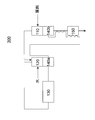
- FIG. 1 is a conceptual diagram illustrating an example of a schematic configuration of a hydrogen generator according to a first embodiment.
- FIG. 2 is a conceptual diagram illustrating an example of a schematic configuration of a hydrogen generator according to a second embodiment.
- FIG. 3 is a conceptual diagram illustrating an example of a schematic configuration of a hydrogen generator according to Modification 1 of the second embodiment.
- FIG. 4 is a conceptual diagram illustrating an example of a schematic configuration of a hydrogen generator according to Modification 2 of the second embodiment.
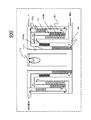
- FIG. 5 is a conceptual diagram illustrating an example of a schematic configuration of a hydrogen generator according to a third embodiment.
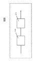
- FIG. 6 is a conceptual diagram showing an example of a schematic configuration of a fuel cell system according to a fourth embodiment.
- the transformer has a temperature gradient such that the upstream is high temperature and the downstream is low temperature. Therefore, when heat exchange is performed between the transformer and the hydrodesulfurizer, the A hydrodesulfurizer that exchanges heat with the vessel is also prone to temperature gradients.
- the hydrodesulfurization catalyst is removed from an appropriate temperature, and the concentration of the sulfur compound in the raw material gas that has passed through the hydrodesulfurizer tends to increase.
- the transformer has a high reaction rate on the upstream side of the high temperature, and since the CO concentration in the hydrogen-containing gas is high and the shift reaction amount is large, most of the CO undergoes a shift reaction, so the calorific value is large and the temperature gradient is large. .
- the reaction rate On the downstream side of the low temperature, the reaction rate is relatively small, and the CO concentration in the hydrogen-containing gas is low, so that the shift reaction amount of CO is small, and the temperature gradient becomes gentle because the calorific value is small.
- the hydrodesulfurizer in the heat exchange between the transformer and the hydrodesulfurizer, by configuring the hydrodesulfurizer to exchange heat mainly with the downstream side of the transformer, the temperature gradient of the hydrodesulfurizer becomes gentler, The hydrodesulfurizer is more easily maintained at an appropriate temperature than the conventional hydrogen generator.
- the hydrogen generator of the first embodiment includes a reformer that generates a hydrogen-containing gas through a reforming reaction using raw materials and steam, a transformer that reduces CO in the hydrogen-containing gas by a shift reaction, and a Provided adjacent to heat exchange with the upstream side, provided adjacent to the evaporator for evaporating water, and adjacent to the downstream side of the transformer, the sulfur compound in the raw material is subjected to hydrodesulfurization reaction A hydrodesulfurizer to be removed.
- the hydrogen generator of the first embodiment includes a reformer that generates a hydrogen-containing gas through a reforming reaction using a raw material and steam, a transformer that reduces CO in the hydrogen-containing gas by a shift reaction,
- the heat exchanger is disposed adjacent to the transformer so as to exchange heat with at least the upstream side of the transformer, and the transformer mainly exchanges heat with the downstream side of the transformer in the heat exchange with the transformer for evaporating water.
- a hydrodesulfurizer for removing sulfur compounds in the raw material by a hydrodesulfurization reaction.
- FIG. 1 is a conceptual diagram showing an example of a schematic configuration of a hydrogen generator 100 according to the first embodiment.
- the hydrogen generator 100 includes a reformer 130 that generates a hydrogen-containing gas through a reforming reaction using a raw material and steam, and a transformer 140 that reduces CO in the hydrogen-containing gas by a shift reaction. , Adjacent to the transformer 140 so as to exchange heat with the upstream side of the transformer 140 and adjacent to the transformer 140 so as to exchange heat with the downstream side of the transformer 140. And a hydrodesulfurizer 110 that removes sulfur compounds in the raw material by a hydrodesulfurization reaction.
- the hydrodesulfurizer has a gentler temperature gradient than the conventional hydrogen generator, and is easily maintained at an appropriate temperature.
- the “upstream side of the transformer 140” refers to the upstream side with respect to the flow of the raw material that passes through the transformer 140
- the “downstream side of the transformer 140” refers to the flow of the raw material that passes through the transformation. Refers to the downstream side.
- the evaporator 120 and the upstream side of the transformer 140 are provided adjacent to each other.
- heat generated by the shift reaction in the transformer 140 can be transmitted to the evaporator 120, and hydrogen can be efficiently generated. That is, since the reaction heat generated by the shift reaction in the transformer 140 can be used for the evaporation of water in the evaporator, the thermal efficiency of the hydrogen generator can be improved.
- the downstream side of the transformer 140 and the hydrodesulfurizer 110 are provided adjacent to each other.
- the hydrodesulfurizer 110 needs to exchange heat with a medium having a small temperature gradient, while the transformer 140 is located upstream of the transformer 140.
- the temperature gradient becomes large, and on the downstream side, the temperature gradient becomes gentle. Therefore, by providing the hydrodesulfurizer 110 adjacent to the downstream side of the transformer 140, the hydrodesulfurizer 110 can perform heat exchange with a medium having a small temperature gradient.
- the vessel 110 can be maintained at an appropriate temperature.
- the hydrogen generator 100 includes a reformer 130 that generates a hydrogen-containing gas through a reforming reaction using raw materials and steam, and a transformer that reduces CO in the hydrogen-containing gas by a shift reaction. 140, an evaporator 120 provided adjacent to the transformer 140 so as to exchange heat with at least the upstream side of the transformer 140, and a downstream side of the transformer 140 in heat exchange with the transformer 140.
- a hydrodesulfurizer 110 that is provided adjacent to the transformer 140 so as to mainly perform heat exchange and removes sulfur compounds in the raw material by a hydrodesulfurization reaction may be provided.
- “provided adjacent to the transformer 140 so as to mainly exchange heat with the downstream side of the transformer 140 in heat exchange with the transformer 140” means that the hydrodesulfurizer 110 is connected to the transformer 140. This means that the adjacent surface area for heat exchange is relatively larger for the downstream side of the transformer 140 than for the upstream side of the transformer 140.
- the hydrogen generator 100 according to the first embodiment includes a hydrodesulfurizer 110, an evaporator 120, a reformer 130, and a transformer 140.
- the hydrodesulfurizer 110 is provided adjacent to the downstream side of the transformer 140 so as to exchange heat, and removes sulfur compounds in the raw material by a hydrodesulfurization reaction.
- a hydrodesulfurization agent for example, a CuZn-based catalyst having both a function of converting a sulfur compound into hydrogen sulfide and a function of adsorbing hydrogen sulfide is used.
- the hydrodesulfurization agent is not limited to this example, and is a CoMo-based catalyst that converts sulfur compounds in the raw material gas into hydrogen sulfide, and a sulfur compound adsorbent that is provided downstream thereof to adsorb and remove hydrogen sulfide. You may comprise with a certain ZnO type catalyst or a CuZn type catalyst.
- the raw material gas that has passed through the hydrodesulfurizer 110 may be mixed with water and passed through the evaporator 120.
- the raw material gas may pass through the reformer 130 after passing through the evaporator 120.
- the evaporator 120 may be a simple space, but may have a spiral configuration in order to increase the heat exchange area. Moreover, the heat exchange area may be further increased by installing a filler that does not directly contribute to the reaction between the raw material gas and water, such as alumina sphere and silica sphere.
- the reformer 130 generates a hydrogen-containing gas from the raw material gas. Specifically, in the reforming catalyst in the reformer 130, a steam reforming reaction with the raw material gas and water proceeds to generate a hydrogen-containing gas.
- a Ni-based, Ru-based or Pt-based catalyst can be generally used.
- the reforming reaction may be in any form as long as it is a reforming reaction using a raw material and steam, and examples thereof include a steam reforming reaction and an autothermal reaction. If the reforming reaction is an autothermal reaction, the hydrogen generator 100 is further provided with an air supply device (not shown) for supplying air to the reformer 130.
- the source gas is a gas containing an organic compound composed of at least carbon and hydrogen, such as city gas mainly composed of methane, natural gas, and LPG.
- a transformer 140 for reducing CO in the hydrogen-containing gas produced by the reformer 130 is provided downstream of the reformer 130.
- a CuZn-based catalyst is used as the shift catalyst, and the shift reaction by the reaction between CO and water vapor in the hydrogen-containing gas proceeds to reduce CO.
- the shift catalyst is not limited to this example, and may be composed of an Fe-based catalyst or a noble metal-based catalyst.
- a space may be provided between the evaporator 120 and the upstream side of the transformer 140. Even in such a case, heat from the upstream side of the transformer 140 can be transmitted to the evaporator 120 through the space, which has the effect of improving the thermal efficiency of the hydrogen generator.
- a fluid having a higher temperature than the fluid flowing through the upstream side of the transformer 140 and the evaporator 120 may flow. Even in this case, the heat from the space can be transferred to the fluid flowing through the transformer 140 and the evaporator 120, so that the heat can be efficiently used.
- the shift reaction occurring in the transformer 140 has a larger calorific value than the hydrodesulfurizer 110.
- the reaction heat in the downstream portion of the shift converter 140 may be configured to be larger than the reaction heat in the hydrodesulfurizer 110.
- the reaction heat in the transformer 140 can be appropriately designed, for example, by adjusting the amount of catalyst in the transformer.
- the evaporator 120 is configured to exchange heat only with the upstream side of the transformer 140. However, it is only necessary to be provided adjacent to the transformer 140 so as to exchange heat with at least the upstream side of the transformer 140. For example, heat is exchanged not only with the upstream side of the transformer 140 but also with the downstream side of the transformer 140. It may be configured as follows.
- the hydrodesulfurizer 110 is provided adjacent to the transformer 140 so as to exchange heat only with the downstream side of the transformer 140.
- the hydrodesulfurizer 110 is not limited to the downstream side of the transformer 140, but also the transformer 140. It may be provided adjacent to the transformer 140 so as to exchange heat with a part of the upstream side. Further, in this case, the hydrodesulfurizer 110 does not exchange heat with a portion of the upstream side of the transformer 140 that has a temperature (for example, 300 ° C.) at which carbon deposition occurs from the raw material in the hydrodesulfurizer. It may be configured.
- the hydrodesulfurizer 110 has a temperature at which the methanation reaction of carbon monoxide or carbon dioxide in the recycle gas proceeds in the hydrodesulfurizer on the upstream side of the converter 140 (for example, 350 You may comprise so that it may not heat-exchange with the part used as (C).
- the hydrogen generator of the second embodiment is the same as that of the hydrogen generator of the first embodiment, but further removes CO in the hydrogen-containing gas that has passed through the converter by at least one of a methanation reaction and an oxidation reaction.
- the transformer includes a first transformer located on the upstream side and a second transformer located on the downstream side, and the hydrogen-containing gas that has passed through the first transformer is removed from the evaporator and CO. Heat exchange with the generator in this order, and then pass through the second transformer.
- FIG. 2 is a conceptual diagram showing an example of a schematic configuration of the hydrogen generator 200 according to the second embodiment.
- the hydrogen generator according to the second embodiment further reduces CO in the hydrogen-containing gas that has passed through the transformer 140 by at least one of a methanation reaction and an oxidation reaction in addition to the hydrogen generator of the first embodiment.
- the CO remover 150 is provided.
- the transformer includes a first transformer 140a located on the upstream side and a second transformer 140b located on the downstream side, and the hydrogen-containing gas that has passed through the first transformer 140a is removed from the evaporator 120 and CO. Heat exchange is performed with the condenser 150 in this order, and then the second transformer 140b is passed.
- Such a configuration makes it easy to stably reduce CO in the hydrogen generator, and shortens the startup time of the hydrogen generator.
- the transformer is divided into a first transformer 140a located on the upstream side and a second transformer 140b located on the downstream side.
- the reaction rate is increased by raising the temperature of the first transformer 140a on the upstream side, and the CO concentration is lowered in a chemical equilibrium by lowering the temperature of the second transformer 140b on the downstream side.
- the temperature distribution can be given as follows. Thereby, the hydrogen generator 200 can easily reduce CO stably.
- the CO remover 150 since the CO remover 150 is located on the most downstream side of the hydrogen generator 200, particularly when the hydrogen generator is started, the temperature at which the CO remover catalyst filled in the CO remover 150 is suitable for the reaction. It takes time to climb up. On the other hand, the temperature of the first transformer 140a is higher than that of the CO remover 150, and becomes higher. Therefore, by transmitting the heat of the hydrogen-containing gas that has passed through the first transformer 140a to the CO removal catalyst, the startup time of the hydrogen generator 200 can be shortened.
- the hydrogen generator 200 includes a hydrodesulfurizer 110, an evaporator 120, a reformer 130, a first transformer 140a, a second transformer 140b, and a CO remover 150. Prepare.
- the first transformer 140a and the second transformer 140b can be configured in the same manner as the transformer 140 described above. Note that different catalyst types may be used separately for the shift catalyst charged in the first shifter 140a and the second shifter 140b.
- the CO remover 150 is provided with a catalyst comprising at least one of a selective oxidation catalyst and a methanation catalyst. Generally, since the CO concentration in the hydrogen-containing gas that has passed through the transformer is about several thousand ppm, CO can be further reduced to several hundred to several ppm.
- a Ru-based or Pt-based catalyst may be used, and an air supply device (not shown) for supplying air may be provided between the second transformer 140b and the CO remover 150. Good.
- the reaction between CO in the hydrogen-containing gas and oxygen in the supplied air may proceed to reduce the CO concentration from several hundred to several ppm.
- a Ru-based or Ni-based catalyst may be used as the methanation catalyst.
- An air supply device is not necessary, and the CO concentration may be reduced from several hundreds to several ppm by the reaction between CO and hydrogen containing hydrogen.
- Modification 1 The hydrogen generator according to Modification 1 is the same as that of the hydrogen generator of the first embodiment, in which the hydrogen-containing gas that has passed through the first converter is the CO remover, and the hydrogen-containing gas before entering the CO remover. In order to pass through the second transformer.
- FIG. 3 is a conceptual diagram showing an example of a schematic configuration of the hydrogen generator 300 according to the first modification.
- the hydrogen generator 300 according to the first modification differs from the hydrogen generator 200 of the second embodiment in that the hydrogen-containing gas that has passed through the first transformer 140a is before entering the CO remover 150 and the CO remover 150. Heat exchange with the hydrogen-containing gas is performed in this order, and then the gas is passed through the second transformer 140b.
- the hydrogen generating apparatus according to the second modification is the same as the hydrogen generating apparatus according to the first embodiment, but the hydrogen-containing gas that has passed through the first converter before entering the evaporator, the CO remover, and the CO remover. And heat exchange in this order, and then pass through the second transformer.
- FIG. 4 is a conceptual diagram showing an example of a schematic configuration of the hydrogen generator 400 according to the second modification.
- the hydrogen generator 400 is configured so that the hydrogen-containing gas that has passed through the first transformer 140a is transferred to the evaporator 120, the CO remover 150, and the CO remover 150. Heat exchange is performed in this order with the hydrogen-containing gas before entering, and after that, it passes through the second transformer 140b.
- the startup time of the hydrogen generator 400 can be shortened.
- the hydrogen generator according to the third embodiment further includes a heater in the hydrogen generator of the second embodiment, and the hydrodesulfurizer is disposed between the heater and the second transformer. ing.
- the hydrodesulfurizer is configured in an annular shape, the heater is disposed on the inner peripheral side of the hydrodesulfurizer, and the second transformer is disposed on the outer peripheral side of the hydrodesulfurizer. Good.
- the second transformer may be configured in an annular shape, and a flow path through which the hydrogen-containing gas after passing through the second transformer flows may be disposed on the outer peripheral side of the second transformer.
- FIG. 5 is a conceptual diagram showing an example of a schematic configuration of the hydrogen generator 500 according to the third embodiment.
- the hydrogen generator 500 according to the third embodiment further includes a heater 210, and the hydrodesulfurizer 110 is provided between the heater 210 and the second transformer 140b. It is arranged to be located in.
- the thermal efficiency of the hydrogen generator 500 can be improved, and an increase in the sulfur compound concentration in the hydrodesulfurizer 110 can be suppressed.
- the hydrogen generator 500 includes the heater 210, and the evaporator 120 is provided adjacent to the first transformer 140a so as to be able to exchange heat. Therefore, since the evaporator 120 can use not only the heat of the heater 210 but also the reaction heat in the first transformer 140a, the amount of heat generated by the heater 210 can be suppressed, and the thermal efficiency of the hydrogen generator 500 can be reduced. Can be improved.
- the hydrodesulfurizer 110 is disposed so as to be positioned between the heater 210 and the second transformer 140b.
- the heater 210 and the second transformer 140b are disposed on the outer periphery of the hydrodesulfurizer 110, it is possible to suppress the temperature of the hydrodesulfurizer 110 from being lowered. Therefore, it is possible to suppress a decrease in reaction efficiency of the hydrodesulfurizer 110 and an increase in the concentration of sulfur compounds.
- the hydrogen generator 200 includes a hydrodesulfurizer 110, an evaporator 120, a reformer 130, a first transformer 140a, a second transformer 140b, a CO remover 150, A heater 210 is provided.
- the heater 210 can be, for example, a burner, combustion exhaust gas, a reactor, or the like. In the example shown in FIG. 5, a burner is used.
- the heater 210 may be at a higher temperature than the second transformer.
- the heater 210 heats the evaporator 120 and the reformer 130.
- the fuel of the heater 210 may be any fuel, but for example, a hydrogen-containing gas discharged from the reformer 130 is used.
- the CO remover 150 has a cylindrical shape. Further, the hydrodesulfurizer 110 is formed in an annular shape, the heater 210 is disposed on the inner peripheral side of the hydrodesulfurizer 110, and the second transformer 140b is disposed on the outer peripheral side of the hydrodesulfurizer 110. Yes.
- the second transformer 140b is formed in an annular shape, and a flow path 141 through which the hydrogen-containing gas after passing through the second transformer 140b flows is arranged on the outer peripheral side of the second transformer 140b. It is configured to be. With such a configuration, the heat dissipation of the second transformer 140b can be suppressed, and the increase in the CO concentration in the transformer can be suppressed.
- the same modifications as in the first and second embodiments are possible. You may combine 3rd Embodiment and the modification 1 of 2nd Embodiment. You may combine 3rd Embodiment and the modification 2 of 2nd Embodiment.
- FIG. 6 is a schematic diagram illustrating an example of a schematic configuration of a fuel cell system 600 according to the fourth embodiment.
- a fuel cell system includes the hydrogen generator according to any one of the first to third embodiments and a fuel cell that generates power using a hydrogen-containing gas supplied from the hydrogen generator.
- a fuel cell system 600 according to the fourth embodiment includes the hydrogen generator 100 of the first embodiment and a fuel cell 310.
- the fuel cell 310 is a fuel cell that generates power using the hydrogen-containing gas supplied from the hydrogen generator 100.
- the fuel cell 310 may be any type of fuel cell.
- a polymer electrolyte fuel cell (PEFC), a solid oxide fuel cell, or a phosphoric acid fuel cell may be used.
- the fuel cell system 600 generates power using the hydrogen-containing gas supplied from the hydrogen generator 100.
- the same modifications as in the first to third embodiments are possible.
- the fourth embodiment and the second embodiment may be combined. You may combine 4th Embodiment and the modification 1 of 2nd Embodiment. You may combine 4th Embodiment and the modification 2 of 2nd Embodiment.
- the fourth embodiment and the third embodiment may be combined.
- the hydrodesulfurizer 110 and the second transformer 140b are in contact with each other, but may be configured to be adjacent via a space. Further, a fluid having a temperature higher than that flowing through the transformer and the evaporator 120 may flow in the space.
- the raw material gas that has passed through the hydrodesulfurizer 110 is mixed with water, and then passes through the evaporator 120 and the reformer 130.
- the raw material gas that has passed through the hydrodesulfurizer 110 is used.
- the gas and water vapor that has passed through the evaporator 120 may be mixed and then introduced into the reformer 130.
- One embodiment of the present invention is useful as a hydrogen generator and a fuel cell system including the hydrogen generator because the hydrodesulfurizer has a gentler temperature gradient than the conventional one and can be easily maintained at an appropriate temperature.
Landscapes
- Chemical & Material Sciences (AREA)
- Chemical Kinetics & Catalysis (AREA)
- Organic Chemistry (AREA)
- Engineering & Computer Science (AREA)
- General Chemical & Material Sciences (AREA)
- Sustainable Energy (AREA)
- Sustainable Development (AREA)
- Electrochemistry (AREA)
- Life Sciences & Earth Sciences (AREA)
- Manufacturing & Machinery (AREA)
- Health & Medical Sciences (AREA)
- General Health & Medical Sciences (AREA)
- Combustion & Propulsion (AREA)
- Inorganic Chemistry (AREA)
- Hydrogen, Water And Hydrids (AREA)
- Fuel Cell (AREA)
Abstract
Description
変成器は、上記従来技術に記載の通り、上流が高温で、下流が低温となるような温度勾配を有するため、変成器と水添脱硫器との間で熱交換を行う場合には、変成器と熱交換する水添脱硫器も温度勾配が生じ易い。水添脱硫器において温度勾配が生じると、水添脱硫触媒が適温から外れ、水添脱硫器を通過した原料ガス中の硫黄化合物の濃度が上昇し易くなる。
第1実施形態の水素生成装置は、原料と水蒸気を用いて改質反応させ水素含有ガスを生成する改質器と、水素含有ガス中のCOをシフト反応により低減する変成器と、変成器の上流側と熱交換するように隣接して設けられ、水を蒸発させる蒸発器と、変成器の下流側と熱交換するように隣接して設けられ、原料中の硫黄化合物を水添脱硫反応により除去する水添脱硫器と、を備える。
[装置構成]
図1に示すように、第1実施形態にかかる水素生成装置100は、水添脱硫器110と、蒸発器120と、改質器130と、変成器140とを備える。
第2実施形態の水素生成装置は、第1実施形態の水素生成装置において、さらに、変成器を通過した水素含有ガス中のCOをメタン化反応及び酸化反応の少なくともいずれか一方により低減するCO除去器を備え、変成器は、上流側に位置する第1変成器と、下流側に位置する第2変成器とを備え、第1変成器を通過した水素含有ガスが、蒸発器、及びCO除去器とこの順で熱交換し、その後、第2変成器を通過するように構成されている。
第2実施形態にかかる水素生成装置200は、水添脱硫器110と、蒸発器120と、改質器130と、第1変成器140aと、第2変成器140bと、CO除去器150とを備える。
変形例1にかかる水素生成装置は、第1実施形態の水素生成装置において、第1変成器を通過した水素含有ガスが、CO除去器、及びCO除去器に入る前の水素含有ガスとこの順で熱交換し、その後、第2変成器を通過するように構成されている。
変形例2にかかる水素生成装置は、第1実施形態の水素生成装置において、第1変成器を通過した水素含有ガスが、蒸発器、CO除去器、及びCO除去器に入る前の水素含有ガスとこの順で熱交換し、その後、第2変成器を通過するように構成されている。
第3実施形態にかかる水素生成装置は、第2実施形態の水素生成装置において、さらに、加熱器を備え、水添脱硫器は、加熱器と第2変成器の間に位置するように配置されている。
第3実施形態にかかる水素生成装置200は、水添脱硫器110と、蒸発器120と、改質器130と、第1変成器140aと、第2変成器140bと、CO除去器150と、加熱器210を備える。
図6は、第4実施形態にかかる燃料電池システム600の概略構成の一例を示す概略図である。
[システム構成]
第4実施形態にかかる燃料電池システム600は、第1実施形態の水素生成装置100と、燃料電池310とを備える。
従って、上記説明は、例示としてのみ解釈されるべきであり、本発明を実行する最良の態様を当業者に教示する目的で提供されたものである。本発明の精神を逸脱することなく、その構造及び/又は機能の詳細を実質的に変更できる。
110 水添脱硫器
120 蒸発器
130 改質器
140 変成器
140a 第1変成器
140b 第2変成器
141 流路
150 CO除去器
210 加熱器
310 燃料電池
600 燃料電池システム
Claims (8)
- 原料と水蒸気を用いて改質反応させ水素含有ガスを生成する改質器と、
水素含有ガス中のCOをシフト反応により低減する変成器と、
前記変成器の上流側と熱交換するように隣接して設けられ、水を蒸発させる蒸発器と、
前記変成器の下流側と熱交換するように隣接して設けられ、原料中の硫黄化合物を水添脱硫反応により除去する水添脱硫器と、を備える水素生成装置。 - さらに、前記変成器を通過した水素含有ガス中のCOをメタン化反応及び酸化反応の少なくともいずれか一方により低減するCO除去器を備え、
前記変成器は、前記上流側に位置する第1変成器と、前記下流側に位置する第2変成器とを備え、
前記第1変成器を通過した水素含有ガスが、前記蒸発器、及び前記CO除去器とこの順で熱交換し、その後、前記第2変成器を通過するように構成されている、請求項1に記載の水素生成装置。 - 前記第1変成器を通過した水素含有ガスが、前記CO除去器、及び前記CO除去器に入る前の水素含有ガスとこの順で熱交換し、その後、前記第2変成器を通過するように構成されている、請求項1に記載の水素生成装置。
- 前記第1変成器を通過した水素含有ガスが、前記蒸発器、前記CO除去器、及び前記CO除去器に入る前の水素含有ガスとこの順で熱交換し、その後、前記第2変成器を通過するように構成されている、請求項1に記載の水素生成装置。
- さらに、加熱器を備え、
前記水添脱硫器は、前記加熱器と前記第2変成器の間に位置するように配置されている、請求項1-4のいずれか1項に記載の水素生成装置。 - 前記水添脱硫器は環状に構成され、
前記加熱器は前記水添脱硫器の内周側に配設され、
前記第2変成器は前記水添脱硫器の外周側に配設される、請求項5に記載の水素生成装置。 - 前記第2変成器は環状に構成され、
前記第2変成器の外周側に前記第2変成器を通過した後の水素含有ガスが流れる流路が配設されている、請求項6に記載の水素生成装置。 - 請求項1-7のいずれか1項に記載の水素生成装置と、前記水素生成装置より供給される水素含有ガスを用いて発電する燃料電池とを備える燃料電池システム。
Priority Applications (3)
| Application Number | Priority Date | Filing Date | Title |
|---|---|---|---|
| EP13807136.0A EP2865642B1 (en) | 2012-06-22 | 2013-06-21 | Hydrogen generation device and fuel cell system |
| US14/240,245 US9527055B2 (en) | 2012-06-22 | 2013-06-21 | Hydrogen generator and fuel cell system |
| JP2013552047A JP5468713B1 (ja) | 2012-06-22 | 2013-06-21 | 水素生成装置および燃料電池システム |
Applications Claiming Priority (2)
| Application Number | Priority Date | Filing Date | Title |
|---|---|---|---|
| JP2012140501 | 2012-06-22 | ||
| JP2012-140501 | 2012-06-22 |
Publications (1)
| Publication Number | Publication Date |
|---|---|
| WO2013190851A1 true WO2013190851A1 (ja) | 2013-12-27 |
Family
ID=49768462
Family Applications (1)
| Application Number | Title | Priority Date | Filing Date |
|---|---|---|---|
| PCT/JP2013/003891 Ceased WO2013190851A1 (ja) | 2012-06-22 | 2013-06-21 | 水素生成装置および燃料電池システム |
Country Status (4)
| Country | Link |
|---|---|
| US (1) | US9527055B2 (ja) |
| EP (1) | EP2865642B1 (ja) |
| JP (1) | JP5468713B1 (ja) |
| WO (1) | WO2013190851A1 (ja) |
Cited By (2)
| Publication number | Priority date | Publication date | Assignee | Title |
|---|---|---|---|---|
| JP2016141590A (ja) * | 2015-01-30 | 2016-08-08 | 株式会社ティラド | 水蒸気改質器 |
| JP2016150899A (ja) * | 2015-02-16 | 2016-08-22 | コリア ガス コーポレーション | 燃料処理装置 |
Families Citing this family (4)
| Publication number | Priority date | Publication date | Assignee | Title |
|---|---|---|---|---|
| EP3602668B1 (en) | 2017-03-23 | 2022-01-26 | BAE Systems PLC | Electrical power generation on a vehicle |
| GB2560773A (en) * | 2017-03-23 | 2018-09-26 | Bae Systems Plc | Electrical power generation on a vehicle |
| GB2560771A (en) * | 2017-03-23 | 2018-09-26 | Bae Systems Plc | Electrical power generation on a vehicle |
| EP3602667B1 (en) | 2017-03-23 | 2020-12-16 | BAE SYSTEMS plc | Electrical power generation on a vehicle |
Citations (9)
| Publication number | Priority date | Publication date | Assignee | Title |
|---|---|---|---|---|
| JP2003165709A (ja) * | 2001-11-29 | 2003-06-10 | Toho Gas Co Ltd | 水素製造装置 |
| JP2006199546A (ja) * | 2005-01-21 | 2006-08-03 | Idemitsu Kosan Co Ltd | 水素製造システム |
| JP2009078954A (ja) * | 2007-09-27 | 2009-04-16 | Fuji Electric Holdings Co Ltd | 改質装置 |
| JP2009096706A (ja) * | 2007-09-27 | 2009-05-07 | Sanyo Electric Co Ltd | 燃料電池用改質装置 |
| JP2009256120A (ja) * | 2008-04-14 | 2009-11-05 | T Rad Co Ltd | 改質装置 |
| JP2011207713A (ja) * | 2010-03-30 | 2011-10-20 | Jx Nippon Oil & Energy Corp | 水素製造装置及び燃料電池システム |
| JP2011207715A (ja) * | 2010-03-30 | 2011-10-20 | Jx Nippon Oil & Energy Corp | 水素製造装置及び燃料電池システム |
| JP2012041238A (ja) * | 2010-08-20 | 2012-03-01 | Panasonic Corp | 水素生成装置及び燃料電池システム |
| JP2012240893A (ja) * | 2011-05-20 | 2012-12-10 | Panasonic Corp | 水素生成装置 |
Family Cites Families (6)
| Publication number | Priority date | Publication date | Assignee | Title |
|---|---|---|---|---|
| JPH107402A (ja) * | 1996-06-25 | 1998-01-13 | Toshiba Corp | 燃料電池の反応器 |
| JP3975191B2 (ja) * | 2003-10-24 | 2007-09-12 | 株式会社Ihi | 燃料改質装置の燃焼装置 |
| US20060199051A1 (en) * | 2005-03-07 | 2006-09-07 | Dingrong Bai | Combined heat and power system |
| US8178062B2 (en) | 2007-09-27 | 2012-05-15 | Sanyo Electric Co., Ltd. | Reforming apparatus for fuel cell |
| JP5163147B2 (ja) * | 2008-01-23 | 2013-03-13 | 富士電機株式会社 | 熱交換器及び複合型燃料反応器 |
| JP5634729B2 (ja) | 2010-03-30 | 2014-12-03 | Jx日鉱日石エネルギー株式会社 | 水素製造装置及び燃料電池システム |
-
2013
- 2013-06-21 WO PCT/JP2013/003891 patent/WO2013190851A1/ja not_active Ceased
- 2013-06-21 EP EP13807136.0A patent/EP2865642B1/en not_active Not-in-force
- 2013-06-21 US US14/240,245 patent/US9527055B2/en not_active Expired - Fee Related
- 2013-06-21 JP JP2013552047A patent/JP5468713B1/ja not_active Expired - Fee Related
Patent Citations (9)
| Publication number | Priority date | Publication date | Assignee | Title |
|---|---|---|---|---|
| JP2003165709A (ja) * | 2001-11-29 | 2003-06-10 | Toho Gas Co Ltd | 水素製造装置 |
| JP2006199546A (ja) * | 2005-01-21 | 2006-08-03 | Idemitsu Kosan Co Ltd | 水素製造システム |
| JP2009078954A (ja) * | 2007-09-27 | 2009-04-16 | Fuji Electric Holdings Co Ltd | 改質装置 |
| JP2009096706A (ja) * | 2007-09-27 | 2009-05-07 | Sanyo Electric Co Ltd | 燃料電池用改質装置 |
| JP2009256120A (ja) * | 2008-04-14 | 2009-11-05 | T Rad Co Ltd | 改質装置 |
| JP2011207713A (ja) * | 2010-03-30 | 2011-10-20 | Jx Nippon Oil & Energy Corp | 水素製造装置及び燃料電池システム |
| JP2011207715A (ja) * | 2010-03-30 | 2011-10-20 | Jx Nippon Oil & Energy Corp | 水素製造装置及び燃料電池システム |
| JP2012041238A (ja) * | 2010-08-20 | 2012-03-01 | Panasonic Corp | 水素生成装置及び燃料電池システム |
| JP2012240893A (ja) * | 2011-05-20 | 2012-12-10 | Panasonic Corp | 水素生成装置 |
Cited By (2)
| Publication number | Priority date | Publication date | Assignee | Title |
|---|---|---|---|---|
| JP2016141590A (ja) * | 2015-01-30 | 2016-08-08 | 株式会社ティラド | 水蒸気改質器 |
| JP2016150899A (ja) * | 2015-02-16 | 2016-08-22 | コリア ガス コーポレーション | 燃料処理装置 |
Also Published As
| Publication number | Publication date |
|---|---|
| JPWO2013190851A1 (ja) | 2016-02-08 |
| EP2865642A4 (en) | 2015-09-02 |
| JP5468713B1 (ja) | 2014-04-09 |
| EP2865642B1 (en) | 2018-09-19 |
| US9527055B2 (en) | 2016-12-27 |
| US20140212775A1 (en) | 2014-07-31 |
| EP2865642A1 (en) | 2015-04-29 |
Similar Documents
| Publication | Publication Date | Title |
|---|---|---|
| JP5468713B1 (ja) | 水素生成装置および燃料電池システム | |
| US8945784B2 (en) | Hydrogen production apparatus and fuel cell system using the same | |
| JP2012020898A (ja) | 水素生成装置及びそれを備える燃料電池システム | |
| JP2012116666A (ja) | 水素生成装置及びそれを備える燃料電池システム | |
| JP5427326B1 (ja) | 燃料処理装置 | |
| JP5895169B2 (ja) | 水素生成装置 | |
| JP5807167B2 (ja) | 水素生成装置 | |
| JP5539754B2 (ja) | 燃料電池用脱硫器の加熱方法及び燃料電池システム | |
| JP5879552B2 (ja) | 水素生成装置、それを備える燃料電池システム、水素生成装置の運転方法、及び燃料電池システムの運転方法 | |
| JP5531168B2 (ja) | 水素生成装置 | |
| JP2012041238A (ja) | 水素生成装置及び燃料電池システム | |
| JP4764651B2 (ja) | 水素製造装置および燃料電池システム | |
| JP2017077992A (ja) | 水素生成装置及びそれを用いた燃料電池システム | |
| JP5938580B2 (ja) | 水素生成装置 | |
| JP5948605B2 (ja) | 水素生成装置 | |
| JP4479237B2 (ja) | 断熱容器構造 | |
| JP2012246179A (ja) | 水素生成装置、および燃料電池システム | |
| JP6089210B2 (ja) | 水素生成装置 | |
| JP2011136867A (ja) | 改質装置、改質ユニット、および、燃料電池システム | |
| JP2016181369A (ja) | 燃料電池システム | |
| JP2016222497A (ja) | 水素生成装置及びそれを用いた燃料電池システム | |
| JP2013203615A (ja) | 水素生成装置 | |
| JP2012250877A (ja) | 水素生成装置及び燃料電池システム | |
| JP2012153535A (ja) | 水素生成装置及び水素生成装置を備えた燃料電池システム | |
| JP2013227163A (ja) | 水素生成装置及びその運転方法 |
Legal Events
| Date | Code | Title | Description |
|---|---|---|---|
| ENP | Entry into the national phase |
Ref document number: 2013552047 Country of ref document: JP Kind code of ref document: A |
|
| WWE | Wipo information: entry into national phase |
Ref document number: 2013807136 Country of ref document: EP |
|
| 121 | Ep: the epo has been informed by wipo that ep was designated in this application |
Ref document number: 13807136 Country of ref document: EP Kind code of ref document: A1 |
|
| WWE | Wipo information: entry into national phase |
Ref document number: 14240245 Country of ref document: US |
|
| NENP | Non-entry into the national phase |
Ref country code: DE |