WO2013190865A1 - Lit pour bébé - Google Patents
Lit pour bébé Download PDFInfo
- Publication number
- WO2013190865A1 WO2013190865A1 PCT/JP2013/055758 JP2013055758W WO2013190865A1 WO 2013190865 A1 WO2013190865 A1 WO 2013190865A1 JP 2013055758 W JP2013055758 W JP 2013055758W WO 2013190865 A1 WO2013190865 A1 WO 2013190865A1
- Authority
- WO
- WIPO (PCT)
- Prior art keywords
- frame
- front frame
- crib
- folded
- fixing member
- Prior art date
- Legal status (The legal status is an assumption and is not a legal conclusion. Google has not performed a legal analysis and makes no representation as to the accuracy of the status listed.)
- Ceased
Links
Images


Classifications
-
- A—HUMAN NECESSITIES
- A47—FURNITURE; DOMESTIC ARTICLES OR APPLIANCES; COFFEE MILLS; SPICE MILLS; SUCTION CLEANERS IN GENERAL
- A47D—FURNITURE SPECIALLY ADAPTED FOR CHILDREN
- A47D7/00—Children's beds
Definitions
- the present invention relates to an improvement of a baby bed.
- the crib needs to have a sufficient height between the bottom plate and the upper end of the outer peripheral frame to prevent the baby from falling outside. In such a crib, the baby inside is put out. Sometimes you have to bend and lift, putting strain on your arms, shoulders and hips, and hitting your baby's feet on the upper edge of the outer frame.
- Patent Document 1 there is a structure in which the front side frame is slidable up and down. Some are configured to be able to reduce the burden on the arms, shoulders, and lower back by lowering them.
- An object of the present invention is to provide a crib that can reduce the burden when a baby is taken in and out regardless of the height. In order to achieve at least a part of this object, the following measures are taken.
- the present invention is a crib in which the left and right side frames, the front frame, and the rear frame are combined in a rectangular shape in plan view.
- the front frame is divided into a left front frame and a right front frame at the center,
- the left end of the left front frame is connected to the front end of the left side frame via a hinge
- the right end of the right front frame is connected to the front end of the right side frame via a hinge
- the gist of the invention is that each of the left front frame and the right front frame is configured to be opened and closed in a double-sided manner toward the front side via a hinge.
- the left front frame and the right front frame constituting the front frame can be opened and closed in a double-spread shape, and the baby can be easily held and put in and out without bending down by opening it in a double-spread shape.
- the baby can be taken in and out smoothly without obstructing the frame, and the burden on the arms, shoulders and waist can be reduced.
- the left front frame and the right front frame are each composed of a base frame and a center frame.
- a base frame is connected to the side frame via the hinge so as to be pivotable in the front-rear direction
- the folded frame may be connected to the base frame so as to be rotatable in the front-rear direction.
- the left and right front frames can be opened and closed in a double-folded manner by folding the center folding frame with respect to the base frame, respectively. Can be opened and closed.
- a pin member is vertically suspended from a lower end of the folding frame, and a rail member to which the pin member is slidably engaged is provided between the left and right side frames. It can also be assumed. If it carries out like this, when opening and closing in a double-spread form, the pin member is guided by the rail member and slides, and can be opened and closed satisfactorily. Further, since the pin member is engaged with the rail member, the left front frame and the right front frame are not lifted upward.
- the fixing member is composed of an upper fixing member that fixes the upper end side of the left and right folded frame and a lower fixing member that fixes the lower end side of the left and right folded frame. It can also be. If it carries out like this, a front frame can be fixed more reliably with an up-and-down fixing member, the closed state of a front frame can be ensured, and safety improves.
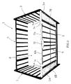
- FIG. 1 is a perspective configuration diagram of a state in which the front frame of the crib is opened in a double-spread shape.
- FIG. 2 is a perspective configuration view seen from the upper side with the front frame of the crib closed.
- FIG. 3 is a perspective configuration diagram seen from the upper side in a state where the front frame is opened like a double door.
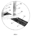
- FIG. 4 is an enlarged perspective view of a portion of a pin member that engages with a rail member for smoothly opening and closing the front frame.
- FIG. 5 is a configuration diagram viewed from the inside of the left side plate of the crib.
- FIG. 6 is a front view of the front frame of the crib.
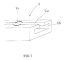
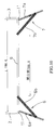
- FIG. 7 is an enlarged cross-sectional perspective view of the rail member of the crib.
- FIG. 1 is a perspective configuration diagram of a state in which the front frame of the crib is opened in a double-spread shape.
- FIG. 2 is a perspective configuration view seen from the upper side with the front frame of the crib closed.
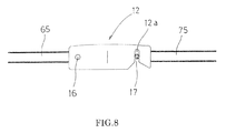
- FIG. 8 is a front configuration diagram of the upper fixing member.
- FIG. 9 is a schematic plan view showing a state in which the front frame is opened in a double-spread shape.
- FIG. 10 is a schematic plan view of a configuration in which the front frame is further opened outward.
- FIG. 11 is a schematic plan view of a state in which the front frame is opened to the maximum.
- FIG. 1 is a perspective configuration diagram of the crib with the front frame opened
- FIG. 2 is a perspective configuration diagram viewed from above with the front frame closed
- FIG. 3 is an illustration of the front frame opened. It is the isometric view block diagram seen from the upper side of the state.
- the crib 1 is assembled in a substantially rectangular shape in plan view with a rear frame 4 connecting the left frame 2 and the right frame 3 and a front frame 5 provided in front of the rear frame 4 in parallel.
- the front frame 5 is composed of a left front frame 6 and a right front frame 7 which are divided at the center on the left and right sides, and the left front frame 6 is connected so that the base frame 6a and the middle frame 6b can rotate.
- the right front frame 7 is also configured by connecting a base frame 7a and a folded frame 7b so as to be rotatable.
- 1 and 3 show a state in which the middle folding frame 6b is folded inward with respect to the base frame 6a constituting the left front frame 6, and the right front frame 7 similarly has a middle folding frame with respect to the base frame 7a.
- the front frame 5 is configured so that the left front frame 6 and the right front frame 7 can be opened forward in a double-opening manner.
- a bottom plate 8 is horizontally disposed, and a shelf plate 10 is disposed in parallel to the lower side of the bottom plate 8.
- the left and right side frames 2 and 3 are formed in the same shape.
- FIG. 1 show a state in which the middle folding frame 6b is folded inward with respect to the base frame 6a constituting the left front frame 6, and the right front frame 7 similarly has a middle folding frame with respect to the base frame 7a.
- the front frame 5 is configured so that the left front frame 6 and the right front frame 7
- the left side plate 2 will be described with reference to a configuration diagram viewed from the inside.
- the left side frame 2 is a front end standing tree 2a on the front end side.
- a rear end standing tree 2b is erected, and a plurality of standing trees 2c, 2c, 2c are arranged in parallel at intervals to form a frame.
- the front end standing tree 2a has a vertical direction.
- Three height adjustment portions 2d, 2d, 2d are formed at intervals, and the height of the bottom plate 8 is set by selecting one of the height adjustment portions 2d, 2d, 2d. It is something that can be done.
- FIG. 6 shows a front view of the front frame 5.
- the front frame 5 is composed of the left front frame 6 and the right front frame 7 as described above, and the left front frame 6 is further folded with the base frame 6a. It consists of a frame 6b.
- the base frame 6 a has a standing tree 63 connected to the front end standing tree 2 a of the left frame 2 via hinges 11, 11, 11, and an upper crossing 61 and a lower crossing 62 extending laterally at the upper and lower ends of the standing tree 63.
- a standing tree 64 is erected in parallel with the standing tree 63, and a cover plate 68 such as a veneer plate is attached between the standing tree 63 and the standing tree 64.
- Rotating shafts 14 and 14 are provided on the upper cross 61 and the lower cross 62 of the base frame 6a.
- the folded frame 6b is formed as a frame with a plurality of standing trees 67, 67, 67 fixed to the upper crosspiece 65 and the lower crosspiece 66 with a space in the horizontal direction.
- the pivot shaft 14 is loosely inserted into the upper crosspiece 65 so as to overlap the lower side of the upper crosspiece 61 of the frame 6a.
- the folded frame 6b can be rotated in the front-rear direction with respect to the base frame 6a via the upper and lower rotation shafts 14 and 14.
- the right front frame 7 is also formed in the same shape, and the folded frame 7b is configured to be rotatable in the front-rear direction with respect to the base frame 7a via the rotation shafts 14 and 14.
- a cover plate 78 such as a veneer plate is provided between the standing trees 73 and 74 constituting the base frame 7a.
- the left front frame 6 and the right front frame 7 can be rotated in the front-rear direction via the hinges 11, 11, 11, and further, the folded frames 6b, 7b can be connected to the base frame via the rotation shafts 14, 14. It is comprised so that it can be rotated in the front-back direction with respect to 6a, 7a.
- a rail member 9 that connects the left frame 2 and the right frame 3 is provided horizontally at the lower portion of the left frame 2 and the right frame 3. That is, as shown in FIG. 6, the rail member 9 is provided between the front end standing tree 2 a of the left frame 2 and the front end standing tree 3 a of the right frame 3 via the fixing screws 20 and 20.
- the rail member 9 has a structure as shown in an enlarged perspective view in FIG.
- An upper surface groove 9a extending in the lateral direction is formed downward in a central portion in the front-rear direction on the upper surface side.
- a guide groove 9b that is wide in the front-rear direction is formed at the lower end of the upper surface groove 9a so as to extend in the lateral direction.
- a through hole 9c having a diameter substantially equal to the front-rear width of the guide groove 9b is formed at a predetermined position of the upper surface groove 9a toward the guide groove 9b.
- pins are respectively suspended downward.
- Members 15 and 15 are provided vertically, and this pin member 15 is formed with a head portion having a diameter that fits into the guide groove 9b at the lower end of the hanging shaft portion. If the head portion of the pin member 15 is inserted into the guide groove 9b from the through hole 9c, the head portion of the pin member 15 fits into the guide groove 9b, and the left front frame 6 and the right front frame against the upward lifting force.
- the pin member 15 can slide along the guide groove 9b. It can be opened laterally That is, when the left front frame 6 and the right front frame 7 are opened, the middle folded frame 6b is folded inside the base frame 6a, and the middle folded frame 7b is folded inside the base frame 7a. It can be opened and closed.
- an upper fixing member 12 as shown in a front view in FIG. 8 is provided, and the upper fixing member 12 is provided with the left front frame 6. It is rotatably attached to the upper crosspiece 65 of the middle folding frame 6b through the rotation pin 16.
- the upper crosspiece 75 of the middle folding frame 7b of the right front frame 7 is provided with an engagement pin 17.
- the upper fixing member 12 is engaged with the engaging pin 17 by rotating the engaging vertical groove 12a of the downward opening formed in the upper fixing member 12 downward from above.
- the left and right middle folding frames 6b and 7b can be connected and fixed via each other.
- the engaging pin 17 can be provided with a tightening member that presses the upper fixing member 12 backward.
- a lower fixing member 13 that can be fastened to the front surface of the bottom plate 8 is provided as shown in FIG.
- the lower fixing member 13 In the closed state of the left front frame 6 and the right front frame 7, the lower fixing member 13 is connected to the standing tree 67 at the right end of the folding frame 6b and the middle.
- the middle folded frames 6b and 7b are placed on the front surface of the bottom plate 8 by straddling the front side of the standing tree 77 at the left end of the folded frame 7b and hitting the head from the front side and fastening the screw shaft portion to the front surface of the bottom plate 8. Pressed and fixed.
- the upper fixing member 12 and the lower fixing member 13 can secure a strong closed state and can improve safety.
- FIG. 9 shows a state in which the left and right front frames 6 and 7 are opened in a double-spread shape so that the opening between the left front frame 6 and the right front frame 7 has an opening width of 646 mm. Furthermore, in FIG. 10, it opened so that the opening width of an opening part might be set to 788 mm. Further, in FIG.
- the left and right base frames 6a and 7a are opened to the outside of the left and right side frames 2 and 3, and the opening width of the opening is 837.6 mm. That is, the distance between the left and right side frames 2 and 3 is 1,198 mm, but a very wide opening width close to that can be secured, and it is easy to stand up after holding the baby, The burden on the shoulders and waist is extremely low.
Landscapes
- Housing For Livestock And Birds (AREA)
- Carriages For Children, Sleds, And Other Hand-Operated Vehicles (AREA)
Applications Claiming Priority (2)
| Application Number | Priority Date | Filing Date | Title |
|---|---|---|---|
| JP2012-003771U | 2012-06-21 | ||
| JP2012003771U JP3178145U (ja) | 2012-06-21 | 2012-06-21 | ベビーベッド |
Publications (1)
| Publication Number | Publication Date |
|---|---|
| WO2013190865A1 true WO2013190865A1 (fr) | 2013-12-27 |
Family
ID=48004905
Family Applications (1)
| Application Number | Title | Priority Date | Filing Date |
|---|---|---|---|
| PCT/JP2013/055758 Ceased WO2013190865A1 (fr) | 2012-06-21 | 2013-02-22 | Lit pour bébé |
Country Status (2)
| Country | Link |
|---|---|
| JP (1) | JP3178145U (fr) |
| WO (1) | WO2013190865A1 (fr) |
Cited By (2)
| Publication number | Priority date | Publication date | Assignee | Title |
|---|---|---|---|---|
| US20140026317A1 (en) * | 2012-05-30 | 2014-01-30 | Peter Kayser | Infant Crib Having Paired Sets of Vertically Hinged Doors for Creating Opening along Entire Side Wall |
| JP6222682B1 (ja) * | 2017-03-10 | 2017-11-01 | 合同会社ディベックス | 幼児用ベッド |
Citations (6)
| Publication number | Priority date | Publication date | Assignee | Title |
|---|---|---|---|---|
| JPS5682282U (fr) * | 1979-11-30 | 1981-07-03 | ||
| JPS56127730U (fr) * | 1980-02-29 | 1981-09-29 | ||
| JPS59169763U (ja) * | 1983-04-27 | 1984-11-13 | 木村寝台工業株式会社 | 寝台 |
| JPH1033319A (ja) * | 1996-07-29 | 1998-02-10 | Kansai Seisakusho:Kk | 小児用ベッド |
| JP3144246U (ja) * | 2008-06-10 | 2008-08-21 | ヨンリエンパンチンミーコンイエクーフェンユーシェンコンスー | フラットシート入れ |
| JP2012061173A (ja) * | 2010-09-16 | 2012-03-29 | Okamura Corp | デスクシステム |
-
2012
- 2012-06-21 JP JP2012003771U patent/JP3178145U/ja not_active Expired - Lifetime
-
2013
- 2013-02-22 WO PCT/JP2013/055758 patent/WO2013190865A1/fr not_active Ceased
Patent Citations (6)
| Publication number | Priority date | Publication date | Assignee | Title |
|---|---|---|---|---|
| JPS5682282U (fr) * | 1979-11-30 | 1981-07-03 | ||
| JPS56127730U (fr) * | 1980-02-29 | 1981-09-29 | ||
| JPS59169763U (ja) * | 1983-04-27 | 1984-11-13 | 木村寝台工業株式会社 | 寝台 |
| JPH1033319A (ja) * | 1996-07-29 | 1998-02-10 | Kansai Seisakusho:Kk | 小児用ベッド |
| JP3144246U (ja) * | 2008-06-10 | 2008-08-21 | ヨンリエンパンチンミーコンイエクーフェンユーシェンコンスー | フラットシート入れ |
| JP2012061173A (ja) * | 2010-09-16 | 2012-03-29 | Okamura Corp | デスクシステム |
Cited By (4)
| Publication number | Priority date | Publication date | Assignee | Title |
|---|---|---|---|---|
| US20140026317A1 (en) * | 2012-05-30 | 2014-01-30 | Peter Kayser | Infant Crib Having Paired Sets of Vertically Hinged Doors for Creating Opening along Entire Side Wall |
| US8918929B2 (en) * | 2012-05-30 | 2014-12-30 | Peter Kayser | Infant crib having paired sets of vertically hinged doors for creating opening along entire side wall |
| JP6222682B1 (ja) * | 2017-03-10 | 2017-11-01 | 合同会社ディベックス | 幼児用ベッド |
| JP2018057805A (ja) * | 2017-03-10 | 2018-04-12 | 合同会社ディベックス | 幼児用ベッド |
Also Published As
| Publication number | Publication date |
|---|---|
| JP3178145U (ja) | 2012-08-30 |
Similar Documents
| Publication | Publication Date | Title |
|---|---|---|
| EP1959077B1 (fr) | Dispositif d'ouverture/fermeture pour trappe double d'un meuble | |
| KR101969136B1 (ko) | 높낮이 조절 가능한 책상 | |
| US11350735B2 (en) | Folding stool or folding table | |
| US7752689B1 (en) | Crib with pivoting and sliding drop side rail | |
| US9777521B2 (en) | Enhanced hinge and method for pivotally and removably connecting a member with a structure | |
| WO2015149695A1 (fr) | Mécanisme de support fixe, mécanisme de pliage et table de pliage | |
| JP5224844B2 (ja) | 棚構造 | |
| WO2013079066A3 (fr) | Porte de sécurité pour enfants | |
| KR20180006015A (ko) | 커튼레일 조립체 | |
| JP3178145U (ja) | ベビーベッド | |
| CN203308376U (zh) | 一种高空作业台 | |
| KR101311425B1 (ko) | 창호의 힌지 구조물 | |
| JP5209522B2 (ja) | 天板スライド式机 | |
| JP3183519U (ja) | 間仕切型二段ベッド | |
| KR20190066818A (ko) | 안전 서랍장 | |
| JP2015031032A (ja) | 枠組み足場用幅木 | |
| KR20130019162A (ko) | 도어의 여닫이 장치 | |
| KR200454897Y1 (ko) | 양방향 도어 스토퍼 | |
| CN103726753A (zh) | 平开折叠门 | |
| JP5165340B2 (ja) | 折り畳みデスクの安全装置 | |
| JP6268643B2 (ja) | 昇降収納装置 | |
| KR20170129074A (ko) | 서랍장 | |
| JP5924664B2 (ja) | 昇降棚用取っ手を有する昇降棚 | |
| KR20160056421A (ko) | 책상상판의 각도조절가능한 책상 | |
| KR101599964B1 (ko) | 물품 거치대 |
Legal Events
| Date | Code | Title | Description |
|---|---|---|---|
| 121 | Ep: the epo has been informed by wipo that ep was designated in this application |
Ref document number: 13807151 Country of ref document: EP Kind code of ref document: A1 |
|
| NENP | Non-entry into the national phase |
Ref country code: DE |
|
| 122 | Ep: pct application non-entry in european phase |
Ref document number: 13807151 Country of ref document: EP Kind code of ref document: A1 |