WO2013191000A1 - リニアアクチュエータ及びリニアアクチュエータの溝加工方法 - Google Patents
リニアアクチュエータ及びリニアアクチュエータの溝加工方法 Download PDFInfo
- Publication number
- WO2013191000A1 WO2013191000A1 PCT/JP2013/065621 JP2013065621W WO2013191000A1 WO 2013191000 A1 WO2013191000 A1 WO 2013191000A1 JP 2013065621 W JP2013065621 W JP 2013065621W WO 2013191000 A1 WO2013191000 A1 WO 2013191000A1
- Authority
- WO
- WIPO (PCT)
- Prior art keywords
- tube
- linear actuator
- chamber
- rod
- axial direction
- Prior art date
- Legal status (The legal status is an assumption and is not a legal conclusion. Google has not performed a legal analysis and makes no representation as to the accuracy of the status listed.)
- Ceased
Links
Images


Classifications
-
- H—ELECTRICITY
- H01—ELECTRIC ELEMENTS
- H01F—MAGNETS; INDUCTANCES; TRANSFORMERS; SELECTION OF MATERIALS FOR THEIR MAGNETIC PROPERTIES
- H01F7/00—Magnets
- H01F7/06—Electromagnets; Actuators including electromagnets
- H01F7/08—Electromagnets; Actuators including electromagnets with armatures
- H01F7/16—Rectilinearly-movable armatures
- H01F7/1607—Armatures entering the winding
- H01F7/1615—Armatures or stationary parts of magnetic circuit having permanent magnet
-
- F—MECHANICAL ENGINEERING; LIGHTING; HEATING; WEAPONS; BLASTING
- F16—ENGINEERING ELEMENTS AND UNITS; GENERAL MEASURES FOR PRODUCING AND MAINTAINING EFFECTIVE FUNCTIONING OF MACHINES OR INSTALLATIONS; THERMAL INSULATION IN GENERAL
- F16F—SPRINGS; SHOCK-ABSORBERS; MEANS FOR DAMPING VIBRATION
- F16F15/00—Suppression of vibrations in systems; Means or arrangements for avoiding or reducing out-of-balance forces, e.g. due to motion
- F16F15/02—Suppression of vibrations of non-rotating, e.g. reciprocating systems; Suppression of vibrations of rotating systems by use of members not moving with the rotating systems
- F16F15/03—Suppression of vibrations of non-rotating, e.g. reciprocating systems; Suppression of vibrations of rotating systems by use of members not moving with the rotating systems using magnetic or electromagnetic means
-
- H—ELECTRICITY
- H02—GENERATION; CONVERSION OR DISTRIBUTION OF ELECTRIC POWER
- H02K—DYNAMO-ELECTRIC MACHINES
- H02K41/00—Propulsion systems in which a rigid body is moved along a path due to dynamo-electric interaction between the body and a magnetic field travelling along the path
- H02K41/02—Linear motors; Sectional motors
- H02K41/03—Synchronous motors; Motors moving step by step; Reluctance motors
- H02K41/031—Synchronous motors; Motors moving step by step; Reluctance motors of the permanent magnet type
-
- B—PERFORMING OPERATIONS; TRANSPORTING
- B60—VEHICLES IN GENERAL
- B60G—VEHICLE SUSPENSION ARRANGEMENTS
- B60G2202/00—Indexing codes relating to the type of spring, damper or actuator
- B60G2202/40—Type of actuator
- B60G2202/42—Electric actuator
- B60G2202/422—Linear motor
-
- B—PERFORMING OPERATIONS; TRANSPORTING
- B60—VEHICLES IN GENERAL
- B60G—VEHICLE SUSPENSION ARRANGEMENTS
- B60G2202/00—Indexing codes relating to the type of spring, damper or actuator
- B60G2202/40—Type of actuator
- B60G2202/44—Axial actuator, e.g. telescopic
-
- B—PERFORMING OPERATIONS; TRANSPORTING
- B60—VEHICLES IN GENERAL
- B60G—VEHICLE SUSPENSION ARRANGEMENTS
- B60G2600/00—Indexing codes relating to particular elements, systems or processes used on suspension systems or suspension control systems
- B60G2600/22—Magnetic elements
- B60G2600/24—Magnetic elements permanent magnets
-
- H—ELECTRICITY
- H02—GENERATION; CONVERSION OR DISTRIBUTION OF ELECTRIC POWER
- H02K—DYNAMO-ELECTRIC MACHINES
- H02K2205/00—Specific aspects not provided for in the other groups of this subclass relating to casings, enclosures, supports
- H02K2205/12—Machines characterised by means for reducing windage losses or windage noise
-
- Y—GENERAL TAGGING OF NEW TECHNOLOGICAL DEVELOPMENTS; GENERAL TAGGING OF CROSS-SECTIONAL TECHNOLOGIES SPANNING OVER SEVERAL SECTIONS OF THE IPC; TECHNICAL SUBJECTS COVERED BY FORMER USPC CROSS-REFERENCE ART COLLECTIONS [XRACs] AND DIGESTS
- Y10—TECHNICAL SUBJECTS COVERED BY FORMER USPC
- Y10T—TECHNICAL SUBJECTS COVERED BY FORMER US CLASSIFICATION
- Y10T82/00—Turning
- Y10T82/10—Process of turning
Definitions
- the present invention relates to a linear actuator that expands and contracts in the axial direction and a groove processing method of the linear actuator.
- JP 2004-357464A includes a linear actuator that relatively displaces the first tube and the second tube in the axial direction based on an electromagnetic force generated between a permanent magnet provided in the first tube and a coil provided in the second tube. It is disclosed.
- the linear actuator described in JP2004-357464A is a permanent magnet in which a space defined on the end side of the first tube and a space defined on the end side of the second tube are arranged in parallel in the axial direction. It communicates only with a minute gap between the coil and the coil. Therefore, the air resistance in the gap when the linear actuator expands and contracts is relatively large, which hinders the smooth expansion and contraction of the linear actuator.
- An object of the present invention is to provide a linear actuator and a groove processing method for the linear actuator that can reduce air resistance during expansion and contraction.
- a linear actuator that expands and contracts in the axial direction, the first tube, the second tube that is slidably inserted into the first tube, and the end of the first tube.
- a rod whose one end is fixed to the rod, a rod guide which is provided at the other end of the rod and slides with respect to the second tube, a plurality of permanent magnets which are held side by side in the axial direction on the rod,
- a holder that fits into the second tube and holds a plurality of coils facing the permanent magnet; a first chamber defined between one end of the holder and an end of the first tube;
- a linear actuator comprising a second chamber defined between the other end of the holder and the rod guide is provided.
- the holder is formed with an insertion hole for communicating the first chamber and the second chamber and for inserting the rod.
- a communication groove that communicates the first chamber and the second chamber is formed in the second tube along the axial direction.
- FIG. 1 is a sectional view in the axial direction of the linear actuator according to the present embodiment, and shows the linear actuator in a maximum contracted state.
- FIG. 2 is a sectional view in the axial direction of the linear actuator according to the present embodiment, and shows the linear actuator in the maximum extended state.
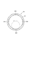
- FIG. 3 is a radial cross-sectional view of the inner tube constituting the second tube of the linear actuator.
- the linear actuator 100 according to the present embodiment will be described with reference to FIGS.
- the linear actuator 100 is used as a vibration control actuator that suppresses vibrations in automobiles, railway vehicles, buildings, and the like.
- the linear actuator 100 includes a first tube 10, a second tube 20 that is slidably inserted into the first tube 10, and a rod 30 that is fixed to an end of the first tube 10 and holds a permanent magnet 31.
- the coil holder 40 is provided so as to be fitted in the second tube 20 and holds the coil 41 facing the permanent magnet 31.
- the linear actuator 100 is disposed between two members that move relative to each other via a connecting portion 1 provided in the first tube 10 and a connecting shaft 2 provided in the second tube 20.
- a thrust (electromagnetic force) for driving the rod 30 in the axial direction is generated according to the current flowing through the coil 41, and the first tube 10 and the second tube 20 are relatively displaced based on this thrust.
- the linear actuator 100 expands and contracts between the maximum contracted position shown in FIG. 1 and the maximum extended position shown in FIG.
- the first tube 10 includes a cylindrical outer tube 11 that is open at both ends, and a cap 12 that is attached to one end of the outer tube 11. One end of the first tube 10 is closed by a cap 12, and the other end of the first tube 10 is formed as an open end.
- the connecting portion 1 is fixed to the outer surface of the cap 12.
- the second tube 20 includes a cylindrical base portion 21, an inner tube 22 fixed to one end side of the base portion 21, and a guide tube 23 fixed to the other end side of the base portion 21.
- the base portion 21 is a cylindrical member that is open at both ends.
- a pair of connecting shafts 2 protruding in the radial direction are fixed to the outer periphery of the base portion 21. These connecting shafts 2 are provided at positions shifted by 180 ° in the circumferential direction.
- the second tube 20 is connected to one of the two members that move relative to each other via the connecting shaft 2, and the first tube 10 is connected to the other of the two members that move relative to each other via the connecting portion 1.
- the inner tube 22 is a cylindrical member that is open at both ends.
- the inner tube 22 is inserted into the outer tube 11 of the first tube 10 while being installed on the base portion 21.
- an annular bearing 24 that is in sliding contact with the inner periphery of the outer tube 11 is provided.
- An annular bearing 13 that is in sliding contact with the outer periphery of the inner tube 22 is provided on the inner periphery of the opening end of the outer tube 11 on the inner tube 22 insertion side.
- the outer tube 11 of the first tube 10 and the inner tube 22 of the second tube 20 slide smoothly through these bearings 13 and 24.
- the guide tube 23 is a cylindrical member that is open at both ends.
- a rod guide 50 fixed to the tip of the rod 30 is slidably provided.
- the rod 30 is a rod-shaped member having a hollow portion 30A.
- One end of the rod 30 is fixed to the cap 12 constituting the end of the first tube 10.
- the rod guide 50 is fixed to the other end of the rod 30.
- a plurality of permanent magnets 31 are held side by side in the axial direction.
- the permanent magnet 31 is formed in a columnar shape and is magnetized so that an N pole and an S pole appear in the axial direction.
- Adjacent permanent magnets 31 are arranged so that the same poles face each other.
- a yoke 32 is provided between the adjacent permanent magnets 31. Note that the yoke 32 is not necessarily provided, and the permanent magnets 31 may be directly adjacent to each other.
- the coil holder 40 is a cylindrical member, and is provided by being fitted to the inner periphery of the base portion 21 of the second tube 20 and the inner tube 22.
- the inner diameter of the base portion 21 is formed larger than the inner diameter of the inner tube 22, and the coil holder 40 is fitted to the inner diameter of the inner tube 22 and the large diameter portion 42 that fits to the inner circumference of the base portion 21. And a small diameter portion 43.
- the coil holder 40 also has an insertion hole 44 through which the rod 30 is inserted in the axial direction.
- An annular recess 43A is formed on the inner peripheral surface of the small diameter portion 43 constituting the insertion hole 44, and a plurality of coils 41 are fixed in the annular recess 43A.
- the plurality of coils 41 are arranged in parallel along the axial direction so as to face the permanent magnet 31.
- the current supplied to the coil 41 is controlled by a controller installed outside the linear actuator 100 or the like.
- the controller controls the magnitude and direction of the current supplied to the coil 41 based on the relative position information of the coil 41 and the permanent magnet 31 detected by a position sensor (not shown). As a result, the thrust generated by the linear actuator 100 and the thrust generation direction (stretching direction) are adjusted.
- the position sensor is a Hall element that generates a Hall voltage corresponding to the strength of the magnetic field, and is embedded in the large-diameter portion 42 of the coil holder 40.
- the linear actuator 100 when a current in a predetermined direction is passed through the coil 41, a thrust force that drives the rod 30 rightward in FIG. 1 is generated.
- the outer tube 11 of the first tube 10 moves rightward while sliding with respect to the inner tube 22 of the second tube 20, and the linear actuator 100 extends.
- a protruding end 23A that protrudes inward is formed at the fixed end of the guide tube 23.
- the open end of the outer tube 11 comes into contact with the right end portion of the base portion 21, and further movement of the rod 30 is restricted.
- the open end of the outer tube 11 functions as a stopper.
- the linear actuator 100 configured as described above includes a first chamber 61 as a space between one end of the coil holder 40 and the cap 12 of the first tube 10 as shown in FIG.
- a second chamber 62 is defined as a space between the other end of the holder 40 and the rod guide 50 disposed in the guide tube 23.
- the first chamber 61 and the second chamber 62 communicate with each other through the insertion hole 44 of the coil holder 40. That is, the first chamber 61 and the second chamber 62 communicate with each other through an annular gap 63 formed between the inner periphery of the coil holder 40 constituting the insertion hole 44 and the outer periphery of the rod 30.
- a communication groove 22 ⁇ / b> A for communicating the first chamber 61 and the second chamber 62 is provided in the inner peripheral surface of the inner tube 22 constituting the second tube 20. ing.
- Four communication grooves 22A are formed at equal intervals in the circumferential direction, and these communication grooves 22A extend along the axial direction.
- the radial cross section of the communication groove 22A is formed as an arcuate cross section.
- the communication groove 22A is formed by setting the inner tube 22 on a lathe so that the cutting tool is inserted into the inner tube 22 (attachment process), and then rotating the cutting tool to cut the inner peripheral surface of the inner tube 22.
- 3 is formed in an arc shape (cutting process).
- the broken line in FIG. 3 shows the locus of the cutting edge of the cutting tool.
- the communication groove 22 ⁇ / b> A extends from the position facing the first chamber 61 over the end of the inner tube 22.
- the communication groove 22A at the end of the inner tube 22 communicates with the second chamber 62 via through holes 42A and 23B that penetrate the large diameter portion 42 of the coil holder 40 and the protruding portion 23A of the guide tube 23 in the axial direction. Yes.
- the through holes 42A and 23B are provided corresponding to the positions where the communication grooves 22A are formed.
- the volume of the first chamber 61 is increased and the volume of the second chamber 62 is reduced, so that the air in the second chamber 62 passes through the annular gap 63, the through holes 42A and 23B, and the communication groove 22A. To the first chamber 61.
- the linear actuator 100 contracts, the volume of the first chamber 61 is reduced and the volume of the second chamber 62 is increased, so that the air in the first chamber 61 has an annular gap 63, a communication groove 22A, and a through hole 42A, It moves to the second chamber 62 through 23B.
- the large-diameter portion 42 of the coil holder 40 may be omitted, and the first chamber 61 and the second chamber 62 may be communicated only by the communication groove 22A of the inner tube 22. In this case, it is not necessary to form the through hole 23B in the protrusion 23A of the guide tube 23.
- the protruding portion 23A of the guide tube 23 may be omitted, and the rod guide 50 may come into contact with the left end surface of the large diameter portion 42 of the coil holder 40 at the maximum extension.
- the first chamber 61 and the second chamber 62 communicate with each other through the communication groove 22 ⁇ / b> A of the inner tube 22 and the through hole 42 ⁇ / b> A of the large diameter portion 42.
- the first chamber 61 and the second chamber 62 are communicated with each other through the insertion hole 44 of the coil holder 40 through which the rod 30 is inserted and the communication groove 22A formed in the inner tube 22.
- the air in the two chambers 62 can easily move to each other, and the air resistance during expansion and contraction of the linear actuator 100 can be reduced. Thereby, the expansion / contraction operation
- the cross section in the radial direction of the communication groove 22A of the inner tube 22 is formed in an arc shape.
- a groove process can be easily performed with respect to the inner tube 22, and it becomes possible to reduce the man-hour etc. at the time of a groove process.
- the coil holder 40 includes a small diameter portion 43 that fits into the inner tube 22, and a large diameter portion 42 that fits into the base portion 21, and the communication groove 22A of the inner tube 22
- the first chamber 61 and the second chamber 62 are configured to communicate with each other through the through hole 42 ⁇ / b> A of the large diameter portion 42.
- a position sensor or the like that detects the relative position between the coil 41 and the permanent magnet 31 can be installed in the large diameter portion 42 of the coil holder 40.
- the plurality of permanent magnets 31 are arranged in the hollow portion 30A of the rod 30 and fixed in the axial direction, but the fixing position of the permanent magnet 31 is not limited to this.
- a permanent magnet 31 formed in a ring shape may be externally fitted to the outer periphery of the rod 30, and the plurality of permanent magnets 31 may be arranged and fixed in the axial direction.
- an annular gap 63 that communicates the first chamber 61 and the second chamber 62 is formed between the insertion hole 44 of the coil holder 40 and the outer periphery of the permanent magnet 31.
- a through hole for communicating the second chamber 62 to the outside is formed in the guide rod 50, or a through hole for communicating the first chamber 61 to the outside is formed in the cap 12. May be.
- a filter such as a mesh is preferably provided in the through hole in order to prevent intrusion of dust or the like.
Landscapes
- Engineering & Computer Science (AREA)
- Physics & Mathematics (AREA)
- Electromagnetism (AREA)
- Power Engineering (AREA)
- Chemical & Material Sciences (AREA)
- Combustion & Propulsion (AREA)
- General Engineering & Computer Science (AREA)
- Acoustics & Sound (AREA)
- Aviation & Aerospace Engineering (AREA)
- Mechanical Engineering (AREA)
- Linear Motors (AREA)
- Manufacture Of Motors, Generators (AREA)
Priority Applications (2)
| Application Number | Priority Date | Filing Date | Title |
|---|---|---|---|
| US14/373,813 US9035732B2 (en) | 2012-06-19 | 2013-06-05 | Linear actuator and groove fashioning method for linear actuator |
| EP13807235.0A EP2787614A4 (de) | 2012-06-19 | 2013-06-05 | Linearstellglied und verfahren zur bearbeitung von nuten in diesem linearstellglied |
Applications Claiming Priority (2)
| Application Number | Priority Date | Filing Date | Title |
|---|---|---|---|
| JP2012137973A JP5927058B2 (ja) | 2012-06-19 | 2012-06-19 | リニアアクチュエータ及び溝加工方法 |
| JP2012-137973 | 2012-06-19 |
Publications (1)
| Publication Number | Publication Date |
|---|---|
| WO2013191000A1 true WO2013191000A1 (ja) | 2013-12-27 |
Family
ID=49768601
Family Applications (1)
| Application Number | Title | Priority Date | Filing Date |
|---|---|---|---|
| PCT/JP2013/065621 Ceased WO2013191000A1 (ja) | 2012-06-19 | 2013-06-05 | リニアアクチュエータ及びリニアアクチュエータの溝加工方法 |
Country Status (4)
| Country | Link |
|---|---|
| US (1) | US9035732B2 (de) |
| EP (1) | EP2787614A4 (de) |
| JP (1) | JP5927058B2 (de) |
| WO (1) | WO2013191000A1 (de) |
Families Citing this family (11)
| Publication number | Priority date | Publication date | Assignee | Title |
|---|---|---|---|---|
| JP5530319B2 (ja) * | 2010-09-16 | 2014-06-25 | カヤバ工業株式会社 | リニアアクチュエータ |
| JP5933379B2 (ja) * | 2012-07-25 | 2016-06-08 | Kyb株式会社 | リニアアクチュエータ |
| JP5948391B2 (ja) * | 2014-10-29 | 2016-07-06 | Kyb株式会社 | リニアアクチュエータ |
| JP5948390B2 (ja) * | 2014-10-29 | 2016-07-06 | Kyb株式会社 | リニアアクチュエータ |
| EP3147534B1 (de) * | 2015-09-23 | 2018-09-19 | Mag Soar Sl | Verbesserter magnetischer schwingungsdämpfer mit mechanischer impedanzanpassung |
| NL2020418B1 (en) * | 2018-02-12 | 2019-08-19 | Magnetic Innovations B V | Coil assembly for magnetic actuator, magnetic actuator and manufacturing method |
| US11084349B2 (en) * | 2019-01-31 | 2021-08-10 | Tenneco Automotive Operating Company Inc. | Leaf spring and actuator control systems and methods |
| US20210257896A1 (en) * | 2020-02-17 | 2021-08-19 | Dan Haronian | Movement and Vibration energy harvesting |
| JP7054714B2 (ja) * | 2020-02-17 | 2022-04-14 | 本田技研工業株式会社 | 電動サスペンション装置 |
| US20230318403A1 (en) * | 2020-08-26 | 2023-10-05 | Propitious Technologies, Llc | Magnified linear power generation system |
| US11936269B2 (en) * | 2021-09-22 | 2024-03-19 | Apple Inc. | Haptic engine based on angular resonant actuator with pivot axis and mass center that differ |
Citations (4)
| Publication number | Priority date | Publication date | Assignee | Title |
|---|---|---|---|---|
| JPS63129847A (ja) * | 1986-11-18 | 1988-06-02 | Daishin:Kk | 電磁制御装置 |
| JP2003324934A (ja) * | 2002-04-26 | 2003-11-14 | Tokico Ltd | リニアモータ |
| JP2004357464A (ja) | 2003-05-30 | 2004-12-16 | Tokico Ltd | リニアモータ |
| JP2012065452A (ja) * | 2010-09-16 | 2012-03-29 | Kayaba Ind Co Ltd | リニアアクチュエータ |
Family Cites Families (13)
| Publication number | Priority date | Publication date | Assignee | Title |
|---|---|---|---|---|
| DE8336759U1 (de) * | 1983-04-11 | 1985-11-28 | F & O Electronic Systems GmbH & Co, 6901 Neckarsteinach | Stoßdämpfer mit veränderbarer Dämpfungscharakteristik |
| JPS60183211A (ja) * | 1984-02-29 | 1985-09-18 | Nissan Motor Co Ltd | 車両用サスペンシヨン装置 |
| DE3736695C2 (de) * | 1986-10-31 | 1995-03-23 | Atsugi Motor Parts Co Ltd | Stoßdämpfer mit variabler Dämpfung |
| US5263558A (en) * | 1990-10-20 | 1993-11-23 | Atsugi Unisia Corporation | Electromagnetic strut assembly |
| US5745019A (en) * | 1996-05-16 | 1998-04-28 | Pacesetter, Inc. | Magnetic annunciator |
| US6354607B1 (en) * | 1998-08-26 | 2002-03-12 | Honda Giken Kogyo Kabushiki Kaisha | Stabilizer effectiveness control device |
| US6952060B2 (en) * | 2001-05-07 | 2005-10-04 | Trustees Of Tufts College | Electromagnetic linear generator and shock absorber |
| US6700251B2 (en) * | 2001-11-06 | 2004-03-02 | Citizen Electronics Co., Ltd. | Vibrating device for axially vibrating a movable member |
| EP2012043B1 (de) * | 2006-04-27 | 2018-06-20 | KYB Corporation | Dämpfer |
| JP2008086144A (ja) * | 2006-09-28 | 2008-04-10 | Murata Mach Ltd | リニアモータおよびそれを搭載した工作機械 |
| US8253281B2 (en) * | 2009-02-27 | 2012-08-28 | GM Global Technology Operations LLC | Energy harvesting apparatus incorporated into shock absorber |
| SG187234A1 (en) * | 2010-07-29 | 2013-02-28 | Univ New York State Res Found | Electricity generating shock absorbers |
| JP5648997B2 (ja) * | 2010-09-16 | 2015-01-07 | カヤバ工業株式会社 | リニアアクチュエータ |
-
2012
- 2012-06-19 JP JP2012137973A patent/JP5927058B2/ja active Active
-
2013
- 2013-06-05 US US14/373,813 patent/US9035732B2/en not_active Expired - Fee Related
- 2013-06-05 EP EP13807235.0A patent/EP2787614A4/de not_active Withdrawn
- 2013-06-05 WO PCT/JP2013/065621 patent/WO2013191000A1/ja not_active Ceased
Patent Citations (4)
| Publication number | Priority date | Publication date | Assignee | Title |
|---|---|---|---|---|
| JPS63129847A (ja) * | 1986-11-18 | 1988-06-02 | Daishin:Kk | 電磁制御装置 |
| JP2003324934A (ja) * | 2002-04-26 | 2003-11-14 | Tokico Ltd | リニアモータ |
| JP2004357464A (ja) | 2003-05-30 | 2004-12-16 | Tokico Ltd | リニアモータ |
| JP2012065452A (ja) * | 2010-09-16 | 2012-03-29 | Kayaba Ind Co Ltd | リニアアクチュエータ |
Non-Patent Citations (1)
| Title |
|---|
| See also references of EP2787614A4 |
Also Published As
| Publication number | Publication date |
|---|---|
| EP2787614A1 (de) | 2014-10-08 |
| US9035732B2 (en) | 2015-05-19 |
| JP2014003824A (ja) | 2014-01-09 |
| EP2787614A4 (de) | 2016-08-03 |
| US20150015352A1 (en) | 2015-01-15 |
| JP5927058B2 (ja) | 2016-05-25 |
Similar Documents
| Publication | Publication Date | Title |
|---|---|---|
| JP5927058B2 (ja) | リニアアクチュエータ及び溝加工方法 | |
| JP5530319B2 (ja) | リニアアクチュエータ | |
| JP5927063B2 (ja) | リニアアクチュエータ及びリニアアクチュエータのチューブ組立方法 | |
| WO2012039293A1 (ja) | リニアアクチュエータ | |
| JP5329910B2 (ja) | リニアアクチュエータ | |
| US9525329B2 (en) | Linear actuator | |
| WO2012035979A1 (ja) | リニアアクチュエータ | |
| JP5927266B2 (ja) | リニアアクチュエータ | |
| JP5933379B2 (ja) | リニアアクチュエータ | |
| JP6585894B2 (ja) | リニアアクチュエータ | |
| JP5426935B2 (ja) | リニアアクチュエータ | |
| JP5965963B2 (ja) | リニアアクチュエータ | |
| JP6360774B2 (ja) | リニアアクチュエータ | |
| JP6364317B2 (ja) | リニアアクチュエータ | |
| JP5346199B2 (ja) | リニアアクチュエータ | |
| JP6978150B2 (ja) | リニアモータ及びそれを備えるリニアアクチュエータ | |
| WO2016068148A1 (ja) | リニアアクチュエータ |
Legal Events
| Date | Code | Title | Description |
|---|---|---|---|
| 121 | Ep: the epo has been informed by wipo that ep was designated in this application |
Ref document number: 13807235 Country of ref document: EP Kind code of ref document: A1 |
|
| WWE | Wipo information: entry into national phase |
Ref document number: 2013807235 Country of ref document: EP |
|
| WWE | Wipo information: entry into national phase |
Ref document number: 14373813 Country of ref document: US |
|
| NENP | Non-entry into the national phase |
Ref country code: DE |