WO2013191008A1 - Dispositif de coulée de résine et procédé de coulée de résine - Google Patents
Dispositif de coulée de résine et procédé de coulée de résine Download PDFInfo
- Publication number
- WO2013191008A1 WO2013191008A1 PCT/JP2013/065744 JP2013065744W WO2013191008A1 WO 2013191008 A1 WO2013191008 A1 WO 2013191008A1 JP 2013065744 W JP2013065744 W JP 2013065744W WO 2013191008 A1 WO2013191008 A1 WO 2013191008A1
- Authority
- WO
- WIPO (PCT)
- Prior art keywords
- air
- molding
- molded product
- resin molded
- supply path
- Prior art date
- Legal status (The legal status is an assumption and is not a legal conclusion. Google has not performed a legal analysis and makes no representation as to the accuracy of the status listed.)
- Ceased
Links
Images




Classifications
-
- B—PERFORMING OPERATIONS; TRANSPORTING
- B29—WORKING OF PLASTICS; WORKING OF SUBSTANCES IN A PLASTIC STATE IN GENERAL
- B29C—SHAPING OR JOINING OF PLASTICS; SHAPING OF MATERIAL IN A PLASTIC STATE, NOT OTHERWISE PROVIDED FOR; AFTER-TREATMENT OF THE SHAPED PRODUCTS, e.g. REPAIRING
- B29C45/00—Injection moulding, i.e. forcing the required volume of moulding material through a nozzle into a closed mould; Apparatus therefor
- B29C45/17—Component parts, details or accessories; Auxiliary operations
- B29C45/40—Removing or ejecting moulded articles
- B29C45/43—Removing or ejecting moulded articles using fluid under pressure
-
- B—PERFORMING OPERATIONS; TRANSPORTING
- B29—WORKING OF PLASTICS; WORKING OF SUBSTANCES IN A PLASTIC STATE IN GENERAL
- B29C—SHAPING OR JOINING OF PLASTICS; SHAPING OF MATERIAL IN A PLASTIC STATE, NOT OTHERWISE PROVIDED FOR; AFTER-TREATMENT OF THE SHAPED PRODUCTS, e.g. REPAIRING
- B29C33/00—Moulds or cores; Details thereof or accessories therefor
- B29C33/44—Moulds or cores; Details thereof or accessories therefor with means for, or specially constructed to facilitate, the removal of articles, e.g. of undercut articles
- B29C33/442—Moulds or cores; Details thereof or accessories therefor with means for, or specially constructed to facilitate, the removal of articles, e.g. of undercut articles with mechanical ejector or drive means therefor
-
- B—PERFORMING OPERATIONS; TRANSPORTING
- B29—WORKING OF PLASTICS; WORKING OF SUBSTANCES IN A PLASTIC STATE IN GENERAL
- B29C—SHAPING OR JOINING OF PLASTICS; SHAPING OF MATERIAL IN A PLASTIC STATE, NOT OTHERWISE PROVIDED FOR; AFTER-TREATMENT OF THE SHAPED PRODUCTS, e.g. REPAIRING
- B29C33/00—Moulds or cores; Details thereof or accessories therefor
- B29C33/44—Moulds or cores; Details thereof or accessories therefor with means for, or specially constructed to facilitate, the removal of articles, e.g. of undercut articles
- B29C33/46—Moulds or cores; Details thereof or accessories therefor with means for, or specially constructed to facilitate, the removal of articles, e.g. of undercut articles using fluid pressure
-
- B—PERFORMING OPERATIONS; TRANSPORTING
- B29—WORKING OF PLASTICS; WORKING OF SUBSTANCES IN A PLASTIC STATE IN GENERAL
- B29C—SHAPING OR JOINING OF PLASTICS; SHAPING OF MATERIAL IN A PLASTIC STATE, NOT OTHERWISE PROVIDED FOR; AFTER-TREATMENT OF THE SHAPED PRODUCTS, e.g. REPAIRING
- B29C45/00—Injection moulding, i.e. forcing the required volume of moulding material through a nozzle into a closed mould; Apparatus therefor
- B29C45/17—Component parts, details or accessories; Auxiliary operations
- B29C45/76—Measuring, controlling or regulating
- B29C45/7626—Measuring, controlling or regulating the ejection or removal of moulded articles
-
- B—PERFORMING OPERATIONS; TRANSPORTING
- B29—WORKING OF PLASTICS; WORKING OF SUBSTANCES IN A PLASTIC STATE IN GENERAL
- B29C—SHAPING OR JOINING OF PLASTICS; SHAPING OF MATERIAL IN A PLASTIC STATE, NOT OTHERWISE PROVIDED FOR; AFTER-TREATMENT OF THE SHAPED PRODUCTS, e.g. REPAIRING
- B29C45/00—Injection moulding, i.e. forcing the required volume of moulding material through a nozzle into a closed mould; Apparatus therefor
- B29C45/17—Component parts, details or accessories; Auxiliary operations
- B29C45/76—Measuring, controlling or regulating
- B29C45/768—Detecting defective moulding conditions
-
- B—PERFORMING OPERATIONS; TRANSPORTING
- B29—WORKING OF PLASTICS; WORKING OF SUBSTANCES IN A PLASTIC STATE IN GENERAL
- B29C—SHAPING OR JOINING OF PLASTICS; SHAPING OF MATERIAL IN A PLASTIC STATE, NOT OTHERWISE PROVIDED FOR; AFTER-TREATMENT OF THE SHAPED PRODUCTS, e.g. REPAIRING
- B29C45/00—Injection moulding, i.e. forcing the required volume of moulding material through a nozzle into a closed mould; Apparatus therefor
- B29C45/17—Component parts, details or accessories; Auxiliary operations
- B29C45/76—Measuring, controlling or regulating
- B29C45/80—Measuring, controlling or regulating of relative position of mould parts
-
- B—PERFORMING OPERATIONS; TRANSPORTING
- B29—WORKING OF PLASTICS; WORKING OF SUBSTANCES IN A PLASTIC STATE IN GENERAL
- B29C—SHAPING OR JOINING OF PLASTICS; SHAPING OF MATERIAL IN A PLASTIC STATE, NOT OTHERWISE PROVIDED FOR; AFTER-TREATMENT OF THE SHAPED PRODUCTS, e.g. REPAIRING
- B29C45/00—Injection moulding, i.e. forcing the required volume of moulding material through a nozzle into a closed mould; Apparatus therefor
- B29C45/17—Component parts, details or accessories; Auxiliary operations
- B29C45/84—Safety devices
-
- B—PERFORMING OPERATIONS; TRANSPORTING
- B29—WORKING OF PLASTICS; WORKING OF SUBSTANCES IN A PLASTIC STATE IN GENERAL
- B29C—SHAPING OR JOINING OF PLASTICS; SHAPING OF MATERIAL IN A PLASTIC STATE, NOT OTHERWISE PROVIDED FOR; AFTER-TREATMENT OF THE SHAPED PRODUCTS, e.g. REPAIRING
- B29C45/00—Injection moulding, i.e. forcing the required volume of moulding material through a nozzle into a closed mould; Apparatus therefor
- B29C45/17—Component parts, details or accessories; Auxiliary operations
- B29C45/76—Measuring, controlling or regulating
- B29C45/82—Hydraulic or pneumatic circuits
- B29C2045/822—Pneumatic circuits
-
- B—PERFORMING OPERATIONS; TRANSPORTING
- B29—WORKING OF PLASTICS; WORKING OF SUBSTANCES IN A PLASTIC STATE IN GENERAL
- B29C—SHAPING OR JOINING OF PLASTICS; SHAPING OF MATERIAL IN A PLASTIC STATE, NOT OTHERWISE PROVIDED FOR; AFTER-TREATMENT OF THE SHAPED PRODUCTS, e.g. REPAIRING
- B29C2945/00—Indexing scheme relating to injection moulding, i.e. forcing the required volume of moulding material through a nozzle into a closed mould
- B29C2945/76—Measuring, controlling or regulating
- B29C2945/76003—Measured parameter
- B29C2945/76167—Presence, absence of objects
-
- B—PERFORMING OPERATIONS; TRANSPORTING
- B29—WORKING OF PLASTICS; WORKING OF SUBSTANCES IN A PLASTIC STATE IN GENERAL
- B29C—SHAPING OR JOINING OF PLASTICS; SHAPING OF MATERIAL IN A PLASTIC STATE, NOT OTHERWISE PROVIDED FOR; AFTER-TREATMENT OF THE SHAPED PRODUCTS, e.g. REPAIRING
- B29C45/00—Injection moulding, i.e. forcing the required volume of moulding material through a nozzle into a closed mould; Apparatus therefor
- B29C45/17—Component parts, details or accessories; Auxiliary operations
- B29C45/40—Removing or ejecting moulded articles
- B29C45/4005—Ejector constructions; Ejector operating mechanisms
- B29C45/401—Ejector pin constructions or mountings
Definitions
- the present invention relates to a resin molding apparatus and a resin molding method, and more particularly to a resin molding apparatus and a resin molding method suitable for molding a soft thin resin molded product.
- An injection molding apparatus is widely known and generally used as a resin molding apparatus for molding a resin molded product.
- a technique for removing a resin molded product molded by an injection molding apparatus from a mold using an air ejector is also widely known (for example, see Patent Document 1).
- the resin molded product after the injection molding is in close contact with the molding surface of the molding die in a vacuum state by the pressure at the time of injection molding.
- the resin molded product is removed from the molding die by injecting air with an air ejector between the molding die and the resin molded product that are in close contact with each other in a vacuum state to release the vacuum state.
- Some of these air ejectors contain a movable valve body (rod) that moves forward and backward in the air injection direction and opens and closes an air injection port for injecting air in the air passage.
- This movable valve body is urged in the direction of accommodation in the passage by an urging member such as a spring, and normally closes the air injection port.
- the air injection port is opened by moving in a direction protruding from the air injection port.
- the movable valve body also has a role of projecting a resin molded product by projecting into the molding space from the air ejection port together with air during air ejection.
- the movable valve body When removing the resin molded product, the movable valve body is moved in the direction of the resin molded product by the pressure of the air supplied to the air passage to open the air injection port. As a result, air is injected from the air injection port to release the vacuum state between the resin molded product and the molding surface, and the resin molded product is protruded from the mold by the movable valve body protruding from the air injection port. Demolding is performed. Thereafter, when the supply of air is released, the movable valve body returns to the original position by the urging force of the urging member, and the air injection port is closed. Next, the injection molding and demolding of the resin molded product are continued.
- the movable valve body may not return to the original position for some reason, such as a malfunction of the urging member or the movable valve body being caught. If this return failure of the movable valve body occurs, the mold or the movable valve body may be damaged when the mold is next clamped. In addition, molten resin may enter the air passage from the air injection port, resulting in malfunction or damage of the air ejector. Therefore, there is a demand for the development of a resin molding apparatus and a resin molding method that can detect a malfunction of the air ejector quickly and surely and can quickly recover to a normal state.
- the present invention has been made in view of the above circumstances, a resin molding apparatus and a resin molding that can easily detect a malfunction of an air ejector and can improve the quality of a molded resin molded product. It aims to provide a method.
- the resin molding apparatus of the present invention is formed in a molding die having a molding space having a molding space for injection-molding a soft and thin resin molding product and comprising a concave mold and a convex mold.
- a movable valve body urged in a direction to close the air injection port by an urging member, an air supply path for supplying air from an air supply source to the air path, and an air supply path Air pressure is detected.
- a pressure detection unit and when the resin molded product is removed from the molding space, air is supplied to the air passage with an air pressure larger than the urging force of the urging member via the air supply passage.
- the movable valve body is moved in the protruding direction from the air injection port to open the air injection port, and after demolding, the air passage with an air pressure smaller than the urging force of the urging member via the air supply path
- the air is supplied to the air, and the air pressure is detected by the air pressure detector.
- the resin molding method of the present invention includes a molding step of injecting a resin molded product by injecting a molten resin into a molding space of a concave mold and a convex mold, and a molding surface of the mold using an air ejector.
- a resin molding method comprising: a demolding step of demolding the resin molded product by injecting air between the resin molded product and an operating state detecting step of detecting an operating state of the air ejector.
- a movable valve body freely accommodated in the air passage is urged in the air passage formed in at least one of the concave mold and the convex mold of the mold in the closing direction of the air injection port.
- Air with an air pressure larger than the urging force of the urging member is supplied, the movable valve body is moved in the protruding direction from the air injection port, the air injection port is opened, and the air is formed between the resin molded product and the molding surface.
- Spray the resin molded product to the mold In the operation state detecting step, the air is supplied to the air passage with an air pressure smaller than the urging force of the urging member, and the air pressure detection unit provided in the air supply passage is used to supply air to the air supply passage. It is characterized by detecting a change in pressure.
- the present invention it is possible to easily and accurately detect whether the air ejector is in a good or defective state only by detecting a change in air pressure, thereby improving the quality of the resin molded product to be molded.
- a possible resin molding apparatus and resin molding method can be obtained. Therefore, even if it is a soft thin resin molded product, generation
- the first on-off valve is closed and the second on-off valve is opened, so that the decompressed air is supplied to the air passage, and the movable valve body returns to the original position normally.
- FIG. 7B is a sectional view taken along line XX in FIG. 7A. It is a sectional side view which shows the air injection port part of the resin molding apparatus which concerns on 3rd Example.
- FIG. 10 is a schematic view showing a demolding procedure of a hard thick resin molded product injection-molded by the injection molding apparatus of FIG. 9, and is an enlarged view in the vicinity of an air injection port before demolding the hard thick resin molded product.
- FIG. 10 is a schematic view showing a demolding procedure of a hard thick resin molded product injection-molded by the injection molding apparatus of FIG. 9, and is an enlarged view in the vicinity of an air injection port when demolding the hard thick resin molded product. It is the schematic which shows the state which has demolded the soft thin resin molded product injection-molded with the injection molding apparatus of FIG.
- An injection molding apparatus 1 shown in FIG. 9 is for injection molding a hard thick resin molded product, and includes a molding die 2 including a convex die 2a and a concave die 2b. In a state where the convex mold 2a and the concave mold 2b are closed (clamped), a molding space 3 for molding a resin molded product is formed inside. By injecting molten resin material into the molding space 3 and solidifying it, a hard thick resin molded product is injection molded.
- Air passages 4a and 4b for supplying air are formed inside the convex mold 2a and the concave mold 2b, and air supplied from the air passages 4a and 4b is formed on the molding surfaces 5a and 5b of the convex mold 2a and the concave mold 2b.
- Air injection ports 6 a and 6 b that are injected into the molding space 3 are opened.
- a cylindrical space larger in diameter than the air passages 4a and 4b is formed on the air injection ports 6a and 6b side of the air passages 4a and 4b, and the movable valve bodies 7a and 7b are movable forward and backward in the spaces. Is stored.
- return detection sensors 8a and 8b are provided to detect the return state of the movable valve bodies 7a and 7b by sensing the positions of the movable valve bodies 7a and 7b.
- a magnet sensor or the like is generally used as the return detection sensors 8a and 8b.
- the movable valve bodies 7a and 7b are urged in the valve closing direction by the pressing ridges 9a and 9b.
- the air passages 4a and 4b are connected to, for example, factory air as an air supply source 11 through an air supply path. Air supply to the air passages 4 a and 4 b is controlled by the on-off valve 10.
- FIGS. 9, 10A, and B for example, a process for removing a hard thick resin molded product from the convex mold 2a using such an injection molding apparatus 1 will be described.
- the hard thick resin molded product 12 after the injection molding is in close contact with the molding surface 5a of the convex mold 2a in a vacuum state.
- the movable valve body 7a is accommodated in the air passage 4a, and the air injection port 6a is closed.
- the detection sensor 8a detects the presence of the movable valve body 7a.
- the movable valve body 7a is moved in a direction protruding from the air injection port 6a by the air pressure, further pressing the hard thick resin molded product 12, and the air injection port 6a is opened. Air is injected between the hard thick resin molded product 12 and the molding surface 5a. As a result, while the vacuum contact state is gradually released, it is pulled by the molded product take-out machine, and the reaction force of the hard thick resin molded product 12 to the pressing force or the like acts, and finally the hard thick wall The resin molded product 12 is detached from the molding surface 5a, and the demolding is completed.
- the on-off valve 10 is closed and the supply of air from the air supply source 11 to the air passage 4a is stopped.
- the movable valve body 7a is returned to the original position by the urging force of the pressing ridge 9a, so that the air injection port 6a is closed.
- the return detection sensor 8a senses the return of the movable valve body 7a, it is determined that a series of injection molding processes have been normally performed, and the next resin molded product is injection molded.
- the movable valve element 7a may not return to the original position due to a malfunction of the pressing rib 9a. Therefore, the air injection port 6a remains open, and when the mold is clamped in this state, the movable valve body 7a protruding outward may come into contact with the mold 2 or the like. Further, when molten resin is injected into the molding space 3 with the air injection port 6a opened, the molten resin flows into the air passage 4a from the air injection port 6a, and the movable valve body 7a is fixed in and out. Problems such as inability to operate may occur.
- the injection molding apparatus 1 performs the following control. First, when the return detection sensor 8a cannot sense the return of the movable valve body 7a, an error is notified from the return detection sensor 8a to the equipment side (control side). On the facility side that has received the notification of this error, the operation of the injection molding apparatus 1 is stopped. And after returning the movable valve body 7a to the correct position, the injection molding apparatus 1 is restarted and the operation is resumed. In this way, the operation of the movable valve body 7a is monitored by the return detection sensor 8a, so that a malfunction is detected, and the resin molded product is molded well in the injection molding apparatus 1.
- the inventor performs injection molding of a soft thin skin material used for a vehicle interior front panel of a vehicle such as an automobile, using the general injection molding apparatus 1 as described above. Tried.
- a vehicle interior front panel provided at the front of the vehicle interior is called an instrument panel or a dashboard.
- Such a vehicle interior front panel has a multilayer structure in which a cushion layer and a soft thin skin material are laminated on the surface of a hard core material.
- Such a soft thin skin material is usually manufactured by powder slush molding, vacuum molding, or the like.
- powder slush molding and vacuum forming devices are not widely used nationwide, and the factories and regions where they are installed are limited. For this reason, the present inventor attempted injection molding of the skin material using an injection molding apparatus having a high diffusion rate.
- the hard thick resin molded product has a hardness that is not easily damaged or deformed even when subjected to a strong pressing force from a movable valve body or the like at the time of demolding.
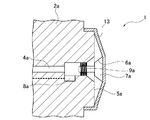
- a resin product such as a skin material is soft and thin, and immediately after injection molding, the temperature is higher than normal temperature. Therefore, the resin product is in a very soft and delicate state and is in close contact with the molding surface. Therefore, as shown in FIG. 11A, when the movable valve body 7a is projected at a normal projecting length (stroke), that is, about 3.0 mm, a strong load is applied only to the contact surface with the movable valve body 7a. Therefore, it was found that a part of the soft thin resin product 13 was stretched and solidified as it was, and the finished product was wrinkled or distorted.
- stroke normal projecting length
- the inventor tried to prevent the elongation of the soft thin resin molded product 13 by shortening the advance / retreat stroke of the movable valve element 7a of the soft thin resin molded product 13 as shown in FIG. 11B.
- the stroke of the movable valve body 7 was set to 2 mm or less, which is substantially the same as the thickness of the soft thin resin molded product 13.
- the air is not lifted unexpectedly and the air is blown slightly from the molding surface 5 without causing the soft thin resin molded product 13 to extend unexpectedly. It was found that the soft thin-walled resin molded product 13 can be easily demolded.
- sensors that detect the distance and position between objects such as a magnet sensor, have not yet been developed that can detect a return failure of an object that advances and retreats with a minute stroke, such as the above-described movable valve element. Accordingly, the inventors have invented the present application by paying attention to a change in the pressure of air that operates the movable valve body.
- FIG. 1 is a perspective view of an instrument panel using a soft resin molded product that is injection-molded by the resin molding apparatus of the first embodiment.
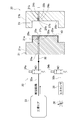
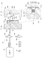
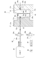
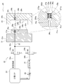
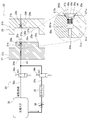
- FIGS. 2 to 6 are schematic views for explaining the resin molding apparatus and the resin molding method according to the first embodiment.
- FIGS. 2 to 4 show the steps of the demolding process for removing the resin molded product from the mold.
- FIG. 5 and FIG. 6 show the procedure of the operation state detection process for detecting whether or not the air ejector has malfunctioned after demolding.
- FIG. 1 shows an example of an instrument panel 100 attached to the front part of a passenger compartment of an automobile or the like.
- Some instrument panels 100 have a multilayer structure in which a cushion layer or a foam layer and a soft thin skin material are laminated on the surface of a hard core material.
- Such an instrument panel 100 has a size of about 1.4 m to 2 m, a height of about 60 cm to 90 cm, a depth of about 40 cm to 90 cm in the longitudinal direction of the vehicle, and a large size having a complicated shape. (Large area).
- the skin material of the instrument panel 100 is also a large area having the same complicated shape.
- the thickness of the skin material with respect to this area is extremely thin, about 1.0 mm to 2.0 mm, and is made of a soft resin material such as synthetic rubber. Therefore, wrinkles and breakage are likely to occur during demolding, and it is delicate.
- the resin molding apparatus and resin molding method of the present embodiment can be suitably used for molding such a soft thin skin material.
- the resin molding apparatus 20 of the first embodiment is soft from the molding surface 21 of the molding die 21 and the molding die 21 including the convex die 21 a and the concave die 21 b for injection molding the soft thin resin molded product 40. And an air ejector 22 for peeling the thin resin molded product 40. Further, although not shown, a molded product take-out machine for taking out the soft thin resin molded product 40 from the mold 21 is also provided. In a state where the convex mold 21a and the concave mold 21b are closed, a molding space 23 for molding the soft thin resin molded product 40 is formed inside.
- the convex mold is formed as a movable mold and the concave mold is formed as a fixed mold.
- the convex mold that is a movable mold is opened, the back side of the product is opened, and then the product surface is peeled off from the molding surface of the concave mold that is a fixed mold.
- the present application is not limited to this, and in this embodiment, as shown in FIG. 2, the concave mold 21b is a movable mold, and the concave mold 21b is opened to open the product surface. . Thereafter, the rear surface of the product is detached from the convex mold 21a which is a fixed mold.
- the molding space 23 is formed between the convex mold 21a and the concave mold 21b when they are clamped.
- the gap of the molding space 23 is also formed to be extremely narrow, about 1.0 mm to 2.0 mm.
- the resin material a molten resin having a very high fluidity is used so that the resin material can reach every corner of the narrow molding space 23.
- the air ejector 22 supplies air to the air passages 24a and 24b formed inside the convex mold 21a and the concave mold 21b, the ejector main bodies 31a and 31b for injecting air from the air paths 24a and 24b, and the air paths 24a and 24b.
- the air supply path 32 to be supplied and an air supply source 33 for supplying factory air to the air supply path 32 are configured.
- the ejector main bodies 31a and 31b are movable to open and close the air injection ports 26a and 26b opened on the molding surfaces 25a and 25b of the convex mold 21a and the concave mold 21b, and the air injection ports 26a and 26b. It has valve bodies 27a and 27b, urging members 29a and 29b for urging the movable valve bodies 27a and 27b, and valve housing spaces 28a and 28b for housing the movable valve bodies 27a and 27b.
- a valve accommodating space 28a for accommodating the movable valve element 27a is provided on the air injection port 26a side of the air passage 24a.
- the movable valve element 27a is accommodated in the valve accommodating space 28a so as to be able to enter and exit from the air injection port 26a to the molding space 23 side, and is always accommodated in the valve accommodating space 28a by the biasing member 29a. It is energized.
- the movable valve body 27a includes a cylindrical shaft portion 271a to which the urging member 29a is connected, and a conical valve portion 272a that gradually increases in diameter in the molding space 23 direction.
- valve housing space 28a also has a cylindrical space 281a having a slightly larger diameter than the shaft portion 271a and a conical space 282a having the same size and shape as the valve portion 272a.
- An inner wall surface of the conical space 282a serves as a valve seat 30a on which the valve portion 272a is seated.
- the urging action of the urging member 29a causes the valve portion 272a of the movable valve body 27a to be seated on the valve seat 30a, whereby the air injection port 26a is hermetically closed, and the surface of the valve portion 272a and the molding are formed.
- the surfaces 25a and 25b are flush (flat). Therefore, it is possible to prevent the molten resin from entering during the injection molding.
- a pressing ridge an elastic member for pressing, a compression spring
- a tensile ridge an elastic member for return, A tension spring
- the biasing member 29a has one end on the air injection port 26a side fixed to the valve accommodating space 28a, and the other end on the air passage 24a side fixed to the shaft portion 271a. Due to the restoring force, the movable valve element 27a is urged in the accommodating direction into the valve accommodating space 28a. And if the movable valve body 27a moves by air pressure and protrudes from the air injection port 26a, since the other end side fixed to the axial part 271a will move together, it will compress further. When the air pressure is released, the compressed urging member 29a is restored (stretched), so that the urging member 29a returns to the original position inside the valve accommodating space 28a.
- the basic configuration of the ejector main body 31b of the concave mold 21b is the same as the basic configuration of the ejector main body 31a of the convex mold 21a, so that each member of the ejector main body 31a of the convex mold 21a in the above description is replaced with the ejector main body 31b of the concave mold 21b.
- the description and the explanation are omitted by replacing each of the members with (the end a of the symbol is replaced with b).
- the air injection ports 26a and 26b of the ejector bodies 31a and 31b of the convex mold 21a and the concave mold 21b are on the outer peripheral edge side of the portion to be a product such as the instrument panel 100 of the soft thin resin molded product 40 to be molded. In addition, it is provided at a position corresponding to a part to be cut from the product in a subsequent process, such as an opening of the product. This is to prevent traces of the air injection ports 26a and 26b and the movable valve bodies 27a and 27b from remaining on the product itself, thereby improving the finish of the product. In each drawing according to the first embodiment, only one set of ejector bodies 31a and 31b is provided.
- the horizontal direction (width direction) and the vertical may be changed as appropriate, such as providing a plurality of sets in the direction (height direction).
- Factory air is supplied from an air supply source 33 to the air passages 24a and 24b via an air supply path 32.
- the air supply path 32 includes a first air supply path 32a that supplies demolding air and a second air supply path 32b that supplies error detection air.
- the first air supply path 32 a and the second air supply path 32 b are provided in parallel with the air supply source 33.
- the first air supply path 32a and the second air supply path 32b are respectively provided with a first on-off valve 34a and a second on-off valve 34b, and the opening and closing of the first air supply path 32a and the second air supply path 32b is controlled. ing.
- the second air supply path 32b is provided with a pressure sensor 35 as an air pressure detection unit, and a pressure reducing valve 36 for supplying the factory air with a reduced pressure between the pressure sensor 35 and the air supply source 33. Is provided. Therefore, air having a pressure lower than that of the factory air is supplied from the second air supply path 32b.
- two types of air having different pressures are used as described above, and each supply is divided into a first air supply path 32a and a second air supply path 32b.
- this application is not limited to this, You may make it supply two types of air with one supply path, and can reduce the number of components, such as a pipe
- An air supply circuit such as the first and second on-off valves 34a and 34b, the pressure sensor 35, and the pressure reducing valve 36, an apparatus for opening and closing the molding die 21, a molded product take-out machine, and other operating members are illustrated. Although not carried out, it is connected to a control circuit (CPU or the like) of the resin molding apparatus 20, and each operation is controlled by a computer.
- a control circuit CPU or the like
- the urging force of the urging members 29a and 29b that urge the movable valve bodies 27a and 27b is smaller than the air pressure of the factory air supplied from the first air supply path 32a, and is supplied from the second air supply path 32b. It adjusts so that it may become larger than the air pressure of the air after pressure reduction. By this adjustment, when factory air is supplied from the first air supply path 32a, the movable valve bodies 27a and 27b move against the urging force of the urging members 29a and 29b, and the air injection ports 26a and 26b are moved. Open the valve. On the other hand, when the pressure-reduced air is supplied from the second air supply path 32b, the urging force of the urging members 29a and 29b wins.
- the movable valve bodies 27a and 27b do not move in the protruding direction from the valve housing spaces 28a and 28b, and the valve closing state of the air injection ports 26a and 26b is maintained.
- the skin material of the instrument panel 100 has a thickness of about 1.0 mm to 2.0 mm.
- the protruding length of the movable valve bodies 27a, 27b from the valve accommodating spaces 28a, 28b is 0.5 mm to 2.0 mm.
- the movable valve bodies 27a, 27b are sized and biased so that the movable valve bodies 27a, 27b protrude from the valve housing spaces 28a, 28b with a maximum projecting length of about 2.0 mm by factory air.
- urging members 29a and 29b are formed.
- the resin molding method detects a molding process for injection molding the soft thin resin molded product 40, a demolding process for removing the soft thin resin molded product 40 by the air ejector 22, and an operating state of the air ejector 22. And an operating state detecting step for determining whether or not to continue the process. These steps are completed from the start of the production line of the instrument panel 100, such as once the molding of one soft thin resin molded product 40 is completed, the process is performed again for the molding of the next soft thin resin molded product 40. It is repeatedly executed until.
- a molten resin is injected into a molding space 23 formed between the convex mold 21a and the concave mold 21b and solidified, whereby the soft thin resin molded product 40 is injection molded.
- the injection and solidification of the molten resin is not particularly shown or described, but can be performed by a conventionally known method.
- the concave mold 21b is opened from the soft thin resin molded product 40 using the air ejector 22 (ejector body 31b).
- the soft thin-walled resin molded product 40 is detached from the convex mold 21a using an air ejector (ejector body 31a) and a product take-out machine (not shown). Since the procedure for detaching the soft thin resin molded product 40 from the concave mold 21b and the convex mold 21a by the air ejector 22 is substantially the same, here, the soft thin resin from the convex mold 21a will be described with reference to FIGS. A procedure for detaching the molded product 40 will be described.
- the soft thin-walled resin molded product 40 before demolding is in close contact with the molding surface 25b of the convex mold 21a in a vacuum state. Moreover, the temperature is higher than room temperature and is in an extremely soft state.
- the first on-off valve 34a is opened, and factory air (hereinafter referred to as “demolding air”) is supplied from the air supply source 33 into the first air supply path 32a.
- the demolding air that has passed through the first air supply path 32a flows into the air passage 24a of the convex mold 21a, and the movable valve element 27a accommodated in the valve accommodating space 28a is used as the urging force of the urging member 29a. Therefore, it is pressed in the direction of movement in the protruding direction into the molding space 23.
- the tip of the movable valve body 27a presses the surface of the soft thin resin molded product 40 and protrudes from the air injection port 26a to the molding space 23 side. And Due to the properties of the soft thin resin molded product 40, the surface of the soft thin resin molded product 40 is elastically deformed by the pressing force of the movable valve body 27a, so that the movable valve body 27a moves and protrudes, and the air injection port 26a opens. Then, air is injected. Due to the air injection pressure and the pressing force of the movable valve body 27a, as shown in the partially enlarged view of FIG.
- the soft thin resin molded product 40 is partially lifted from the molding surface 25a to form a gap. Become. By releasing the mold release air into the gap, the vacuum state between the soft thin resin molded product 40 and the molding surface 25a is gradually released. At the same time as the ejection of the mold release air, a chuck tab (not shown) protruding from the soft thin resin molded product 40 at the time of injection molding is held on the molded product take-out machine (not shown). It is gripped by a member and pulled in the direction of separation from the molding surface 25a. By such an operation, as shown in FIG. 4, the soft thin resin molded product 40 can be peeled from the molding surface 25a.
- the protruding amount of the movable valve element 27a is adjusted to be 2.0 mm at the maximum, the soft thin resin molded product 40 is not stretched to the extent that it cannot be restored by pressing. Therefore, a high-quality soft thin resin molded product 40 free from wrinkles, distortion, breakage, etc. can be obtained.
- FIG. 5 An operation state detection process is demonstrated using FIG. 5, FIG.
- the first on-off valve 34a is closed and the second on-off valve 34b is opened.
- air is supplied to the air passage 24a from the second air supply passage 32b instead of the demolding air from the first air supply passage 32a.
- the air from the second air supply path 32 b is air in a state where the factory air is depressurized by the action of the pressure reducing valve 36.
- This air is used to detect whether the air ejector 22 is in good working condition (hereinafter referred to as “detection air”), and has a pressure smaller than the biasing force of the biasing member 29a as described above. The pressure is reduced.
- the control unit can recognize that the air injection port 26a has been closed, that is, that the movable valve element 27a has returned to normal.
- the second on-off valve 34b is closed and the supply of the detection air to the air passage 24a is stopped.
- the steps after the molding step are repeated for molding the next soft thin resin molded product 40.
- the movable valve bodies 27a and 27b do not hit the opposing molding surfaces 25b and 25a, and the molding die 21 is damaged. Can be prevented.
- the air injection ports 26a and 26b are hermetically sealed by the movable valve bodies 27a and 27b, even if the molten resin is injected into the molding space 23, the molten resin is discharged via the air injection ports 26a and 26b. It is also possible to satisfactorily prevent the intrusion into the inside 22 and solidification. Therefore, the durability of the resin molding apparatus 20 can be improved.
- the control unit that has received the air pressure detection result from the pressure sensor 35 determines that an error has occurred, stops the operation of the resin molding apparatus 20, and stops the production line depending on the situation. Then, the operator takes action such as manually returning the movable valve element 27a of the air ejector 22 in which the error has occurred to the normal position.
- a countermeasure such as replacement of the parts is performed.
- the resin molding apparatus 20 and the production line are restarted, and the resin molding process is resumed.
- the quality of the product can be improved.
- the pressure sensor 35 By using the pressure sensor 35 as described above, it is possible to detect a minute change in the air pressure and quickly and reliably grasp the normality and abnormality of the return of the movable valve element 27a. Therefore, the advance / retreat distance of the movable valve element 27a can be reduced as compared with a magnet sensor or the like that senses by distance. As a result, the protruding length of the movable valve element 27a can be set to a small value of 2.0 mm or less, the elongation of the soft thin resin molded product 40 can be prevented well, and the product quality improvement effect can be enhanced. .
- the demolding air supplied from the first air supply passage and the detection air supplied from the second air supply passage both use factory air as a supply source.
- Factory air is depressurized with a pressure reducing valve.
- the present application is not limited to this, and air that is lower in pressure than the urging member is detected air without depressurizing the release air such as factory air with the pressure reducing valve. May be prepared separately.
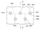
- FIG. 7A is a schematic view of the molding surface 125a of the convex mold 121a as viewed from the front in the vicinity of the air injection port 126a
- FIG. 7B is a cross-sectional view taken along the line XX of FIG. 7A.
- the air passage 124a branches into a plurality of branch passages in the horizontal direction and the vertical direction on the molding surface 125a side, and a plurality of air passages 124a on the molding surface 125a side.
- the air injection port 126a is opened. These air injection ports 126a are provided alternately in the horizontal direction and the vertical direction, as shown in FIG. 7A.
- a valve accommodating space 128a is formed on the air injection port 126a side of each branch passage, and a movable valve element 127a urged in the valve closing direction by the urging member 129a is accommodated therein.
- the air injection port 126a including these is also formed at a site to be removed in a later process such as an opening of a product.
- the plurality of air injection holes 126a are provided in the horizontal direction and the vertical direction. Therefore, it is possible to disperse the load of air and the movable valve body 127a in a large area and soft thin resin molded product in a well-balanced manner and uniformly inject the air.
- the air passage 124a is branched on the air injection port 126a side, but has a single space on the air supply passage side, so that the first and second air supply passages, the first and second on-off valves, the pressure It is not necessary to form a plurality of sensors, air supply sources, etc., and a single circuit (air supply system) may be used.
- any one of the movable valve bodies 127a can be quickly detected with one pressure sensor.
- the resin molding apparatus can be implemented at a low cost and in a compact manner.
- a plurality of air passages may be provided in the mold without branching one air passage 124a, air may be supplied from one air supply system to each air passage, An air supply path or a pressure sensor may be provided on the surface.
- the air passage 124a branches in the horizontal direction and the vertical direction, and a plurality of air injection ports 126a are alternately formed in the horizontal direction and the vertical direction.
- the air passage 224a branches in the vertical direction, and a plurality of air injection ports 226a are formed coaxially in the vertical direction.
- a plurality of sets of such branch passages and air injection ports 226a branched in the vertical direction may be arranged in the horizontal direction.
- the instrument panel 100 includes, as viewed from the side, at least an upper surface portion 100a facing upward, a rear surface portion 100b facing toward the occupant side, and between the upper surface portion 100a and the rear surface portion 100b. It has a curved shape having a bent portion 100c interposed between them and a large surface area. Therefore, a soft thin-walled resin molded product used as a skin material may be bent or bent due to its own weight or the like when taken out from a mold with a molded product take-out machine. In order to prevent such bending and bending from affecting the work efficiency and product quality of demolding, as another different embodiment, it is in the development stage, but a support arm (not shown) is provided in the molding unloader. May be.
- the product is removed using an air ejector while supporting the vertical middle part on the back side of the product, which is the concave shape of the soft thin resin molded product, with the support arm provided in the molded product take-out machine.
- the support arm By providing the support arm in this way, it becomes possible to remove the soft thin-walled resin molded product successfully without causing a shape defect such as bending wrinkles. Thereby, mechanization and automation of the demolding of the soft thin-walled resin molded product can be performed more easily.
- the resin molding apparatus and the resin molding method are applied to the molding of a soft thin resin molded product, but may be applied to the molding of a hard thick resin molded product. Even in the molding of hard and thick resin molded products, it is possible to monitor the operating state of the air ejector by detecting the air pressure. Resin molding is possible.
Landscapes
- Engineering & Computer Science (AREA)
- Mechanical Engineering (AREA)
- Manufacturing & Machinery (AREA)
- Physics & Mathematics (AREA)
- Fluid Mechanics (AREA)
- Moulds For Moulding Plastics Or The Like (AREA)
- Injection Moulding Of Plastics Or The Like (AREA)
Priority Applications (3)
| Application Number | Priority Date | Filing Date | Title |
|---|---|---|---|
| CN201380030785.0A CN104364064B (zh) | 2012-06-20 | 2013-06-06 | 树脂成型装置以及树脂成型方法 |
| EP13807730.0A EP2865507B1 (fr) | 2012-06-20 | 2013-06-06 | Dispositif et procédé de moulage par injection |
| US14/409,125 US10195774B2 (en) | 2012-06-20 | 2013-06-06 | Resin cast device and resin cast method |
Applications Claiming Priority (2)
| Application Number | Priority Date | Filing Date | Title |
|---|---|---|---|
| JP2012-138944 | 2012-06-20 | ||
| JP2012138944A JP5859387B2 (ja) | 2012-06-20 | 2012-06-20 | 樹脂成形装置および樹脂成形方法 |
Publications (1)
| Publication Number | Publication Date |
|---|---|
| WO2013191008A1 true WO2013191008A1 (fr) | 2013-12-27 |
Family
ID=49768609
Family Applications (1)
| Application Number | Title | Priority Date | Filing Date |
|---|---|---|---|
| PCT/JP2013/065744 Ceased WO2013191008A1 (fr) | 2012-06-20 | 2013-06-06 | Dispositif de coulée de résine et procédé de coulée de résine |
Country Status (5)
| Country | Link |
|---|---|
| US (1) | US10195774B2 (fr) |
| EP (1) | EP2865507B1 (fr) |
| JP (1) | JP5859387B2 (fr) |
| CN (1) | CN104364064B (fr) |
| WO (1) | WO2013191008A1 (fr) |
Families Citing this family (11)
| Publication number | Priority date | Publication date | Assignee | Title |
|---|---|---|---|---|
| JP2016185701A (ja) * | 2015-03-27 | 2016-10-27 | 高槻電器工業株式会社 | 金型、金型の制御方法、および半導体装置 |
| CN107650348B (zh) * | 2015-07-14 | 2019-09-27 | 广东台塑智能科技有限公司 | 一种气动式强制脱模机构模具及其使用方法 |
| JP6389502B2 (ja) * | 2016-12-08 | 2018-09-12 | ミネベアミツミ株式会社 | 中継装置および圧力検出装置 |
| EP3762199A1 (fr) * | 2018-03-05 | 2021-01-13 | BAE SYSTEMS plc | Évidement prédéfini |
| JP7463680B2 (ja) * | 2019-09-19 | 2024-04-09 | セイコーエプソン株式会社 | 射出成形システムおよび成形品の製造方法 |
| CN111688119B (zh) * | 2020-05-14 | 2022-02-18 | 佛山市晫尔模具有限公司 | 一种注塑模具结构 |
| KR102518135B1 (ko) * | 2020-06-18 | 2023-04-05 | 주식회사 이노베이션 | 불소수지 성형품의 치수보정장치와 이를 이용한 불소수지 성형품의 제조방법. |
| CN113878823B (zh) * | 2021-09-26 | 2023-09-26 | 博众精工科技股份有限公司 | 一种脱模模组 |
| KR102529395B1 (ko) * | 2021-10-14 | 2023-05-04 | 현대자동차 주식회사 | 압력용기의 사출금형장치 |
| CN116100765B (zh) * | 2023-01-20 | 2026-04-17 | 浙江赛豪实业有限公司 | 一种气体辅助同步顶出机构 |
| CN118617645B (zh) * | 2024-08-14 | 2024-10-29 | 宁波富声达电机有限公司 | 一种基于脱模机全流程控制方法、系统、存储介质及终端 |
Citations (5)
| Publication number | Priority date | Publication date | Assignee | Title |
|---|---|---|---|---|
| JPH02126809U (fr) * | 1989-03-27 | 1990-10-18 | ||
| JPH0663962A (ja) * | 1992-08-21 | 1994-03-08 | Ran Tekkosho:Kk | 金型のエア噴出弁装置 |
| JP2001009880A (ja) | 1999-07-02 | 2001-01-16 | Hitachi Koki Co Ltd | 射出成形機と圧縮エアー制御方法 |
| JP2007125789A (ja) * | 2005-11-04 | 2007-05-24 | Sodick Co Ltd | キャビティの真空を解除する金型装置とその金型装置を含む成形装置 |
| JP2010208165A (ja) * | 2009-03-10 | 2010-09-24 | Bridgestone Corp | 熱可塑性エラストマー成形品の排出方法および熱可塑性エラストマー成形品の金型 |
Family Cites Families (16)
| Publication number | Priority date | Publication date | Assignee | Title |
|---|---|---|---|---|
| NL249952A (fr) * | 1959-03-31 | |||
| US3183292A (en) * | 1962-05-25 | 1965-05-11 | Dvoracek Frank | Plastic molding apparatus and method |
| JPS5030951A (fr) * | 1973-07-18 | 1975-03-27 | ||
| US4364895A (en) * | 1981-07-29 | 1982-12-21 | Underwood J Larry | Fluid-assisted core-release method and apparatus |
| US4521367A (en) * | 1981-11-16 | 1985-06-04 | Underwood J Larry | Mold, process of molding, and article molded by such process |
| US4438065A (en) * | 1982-03-08 | 1984-03-20 | Husky Injection Molding Systems Ltd. | Air ejection of molded containers |
| US4580965A (en) * | 1982-12-20 | 1986-04-08 | Wernecke Robert A | Injection mold safety controls |
| US5273707A (en) * | 1988-12-05 | 1993-12-28 | Icp Systems, Inc. | Method of injection molding |
| ATE155728T1 (de) * | 1988-12-05 | 1997-08-15 | Robert E Carroll | Spritzgiessverfahren |
| US4981430A (en) * | 1989-01-23 | 1991-01-01 | Zimmerman Jr Joseph E | Pneumatically operated mold ejection apparatus |
| JPH05131257A (ja) * | 1991-11-08 | 1993-05-28 | Toyota Motor Corp | 型締め異常検出装置 |
| US5368468A (en) * | 1993-06-09 | 1994-11-29 | Boskovic; Borislav | Air knockout for plastic molds |
| JPH09254188A (ja) * | 1996-03-22 | 1997-09-30 | Toshiba Mach Co Ltd | コネクタ成形用金型のコネクタピン折損検出装置 |
| JP2002172456A (ja) * | 2000-11-30 | 2002-06-18 | Nissan Motor Co Ltd | ダイカスト鋳造用金型のガス抜き装置 |
| CN1473696A (zh) | 2003-08-11 | 2004-02-11 | 卢能晓 | 注塑模的压缩空气脱模法及其模具结构 |
| CN201268078Y (zh) | 2008-08-02 | 2009-07-08 | 俞建江 | 薄壁深腔类模具的压缩空气脱模系统 |
-
2012
- 2012-06-20 JP JP2012138944A patent/JP5859387B2/ja not_active Expired - Fee Related
-
2013
- 2013-06-06 US US14/409,125 patent/US10195774B2/en not_active Expired - Fee Related
- 2013-06-06 WO PCT/JP2013/065744 patent/WO2013191008A1/fr not_active Ceased
- 2013-06-06 CN CN201380030785.0A patent/CN104364064B/zh not_active Expired - Fee Related
- 2013-06-06 EP EP13807730.0A patent/EP2865507B1/fr not_active Not-in-force
Patent Citations (5)
| Publication number | Priority date | Publication date | Assignee | Title |
|---|---|---|---|---|
| JPH02126809U (fr) * | 1989-03-27 | 1990-10-18 | ||
| JPH0663962A (ja) * | 1992-08-21 | 1994-03-08 | Ran Tekkosho:Kk | 金型のエア噴出弁装置 |
| JP2001009880A (ja) | 1999-07-02 | 2001-01-16 | Hitachi Koki Co Ltd | 射出成形機と圧縮エアー制御方法 |
| JP2007125789A (ja) * | 2005-11-04 | 2007-05-24 | Sodick Co Ltd | キャビティの真空を解除する金型装置とその金型装置を含む成形装置 |
| JP2010208165A (ja) * | 2009-03-10 | 2010-09-24 | Bridgestone Corp | 熱可塑性エラストマー成形品の排出方法および熱可塑性エラストマー成形品の金型 |
Non-Patent Citations (1)
| Title |
|---|
| See also references of EP2865507A4 * |
Also Published As
| Publication number | Publication date |
|---|---|
| US20150190956A1 (en) | 2015-07-09 |
| JP2014000767A (ja) | 2014-01-09 |
| US10195774B2 (en) | 2019-02-05 |
| EP2865507B1 (fr) | 2016-05-25 |
| CN104364064A (zh) | 2015-02-18 |
| CN104364064B (zh) | 2016-12-21 |
| EP2865507A1 (fr) | 2015-04-29 |
| EP2865507A4 (fr) | 2015-04-29 |
| JP5859387B2 (ja) | 2016-02-10 |
Similar Documents
| Publication | Publication Date | Title |
|---|---|---|
| JP5859387B2 (ja) | 樹脂成形装置および樹脂成形方法 | |
| JP2002018924A (ja) | 射出成形機における異常検知方法 | |
| WO2010035840A1 (fr) | Procédé de production d’un objet moulé par injection et matrice de moulage par injection | |
| JP2012035469A (ja) | 発泡樹脂成形体の成形方法及びその装置 | |
| CN107443767B (zh) | 注射成型系统 | |
| EP2883676B1 (fr) | Procédé et dispositif permettant de mouler des produits moulé en résine souples et fines | |
| CN104797396B (zh) | 注塑成形机的异常监控方法 | |
| EP2019744B1 (fr) | Systeme permettant d'integrer une piece rapportee a un article moule | |
| JP2022049402A (ja) | 金型、射出成形システム、および成形品の製造方法 | |
| JP2009202484A (ja) | インサート成形方法 | |
| JP2007125789A (ja) | キャビティの真空を解除する金型装置とその金型装置を含む成形装置 | |
| KR101002717B1 (ko) | 사출 성형 장치 및 사출 성형 방법 | |
| CN118003559A (zh) | 表皮一体型内置材料制作装置及方法 | |
| JP5428419B2 (ja) | 樹脂成形品の成形装置、および樹脂成形品の成形方法 | |
| JP5307521B2 (ja) | 樹脂シートの熱成形装置 | |
| JP4378423B1 (ja) | 離型検査装置及びそれに用いられる離型検査方法 | |
| JP2010052322A (ja) | 射出成形機 | |
| JP4205616B2 (ja) | 射出成形機の圧力制御方法 | |
| JP2021133657A (ja) | 突き出し装置の戻り確認装置、金型装置および成形機 | |
| JP4778017B2 (ja) | 射出成形機 | |
| JP2008049674A (ja) | 型締装置の制御方法 | |
| JP2009172770A (ja) | 金型装置及び樹脂成形品の成形方法 | |
| JP4789258B2 (ja) | 成型品の離型方法 | |
| JP2016131995A (ja) | ダイカスト金型 | |
| JP2010143165A (ja) | 射出成形装置用金型。 |
Legal Events
| Date | Code | Title | Description |
|---|---|---|---|
| 121 | Ep: the epo has been informed by wipo that ep was designated in this application |
Ref document number: 13807730 Country of ref document: EP Kind code of ref document: A1 |
|
| WWE | Wipo information: entry into national phase |
Ref document number: 14409125 Country of ref document: US |
|
| NENP | Non-entry into the national phase |
Ref country code: DE |