WO2013191163A1 - Palier coulissant composite et dispositif générateur d'électricité éolien qui utilise ledit palier coulissant composite - Google Patents
Palier coulissant composite et dispositif générateur d'électricité éolien qui utilise ledit palier coulissant composite Download PDFInfo
- Publication number
- WO2013191163A1 WO2013191163A1 PCT/JP2013/066677 JP2013066677W WO2013191163A1 WO 2013191163 A1 WO2013191163 A1 WO 2013191163A1 JP 2013066677 W JP2013066677 W JP 2013066677W WO 2013191163 A1 WO2013191163 A1 WO 2013191163A1
- Authority
- WO
- WIPO (PCT)
- Prior art keywords
- bearing
- ring
- inner ring
- generator
- fixed shaft
- Prior art date
- Legal status (The legal status is an assumption and is not a legal conclusion. Google has not performed a legal analysis and makes no representation as to the accuracy of the status listed.)
- Ceased
Links
Images



Classifications
-
- F—MECHANICAL ENGINEERING; LIGHTING; HEATING; WEAPONS; BLASTING
- F16—ENGINEERING ELEMENTS AND UNITS; GENERAL MEASURES FOR PRODUCING AND MAINTAINING EFFECTIVE FUNCTIONING OF MACHINES OR INSTALLATIONS; THERMAL INSULATION IN GENERAL
- F16C—SHAFTS; FLEXIBLE SHAFTS; ELEMENTS OR CRANKSHAFT MECHANISMS; ROTARY BODIES OTHER THAN GEARING ELEMENTS; BEARINGS
- F16C33/00—Parts of bearings; Special methods for making bearings or parts thereof
- F16C33/02—Parts of sliding-contact bearings
- F16C33/04—Brasses; Bushes; Linings
- F16C33/06—Sliding surface mainly made of metal
- F16C33/10—Construction relative to lubrication
- F16C33/1025—Construction relative to lubrication with liquid, e.g. oil, as lubricant
- F16C33/1045—Details of supply of the liquid to the bearing
- F16C33/1055—Details of supply of the liquid to the bearing from radial inside, e.g. via a passage through the shaft and/or inner sleeve
-
- F—MECHANICAL ENGINEERING; LIGHTING; HEATING; WEAPONS; BLASTING
- F03—MACHINES OR ENGINES FOR LIQUIDS; WIND, SPRING, OR WEIGHT MOTORS; PRODUCING MECHANICAL POWER OR A REACTIVE PROPULSIVE THRUST, NOT OTHERWISE PROVIDED FOR
- F03D—WIND MOTORS
- F03D80/00—Details, components or accessories not provided for in groups F03D1/00 - F03D17/00
- F03D80/70—Bearing or lubricating arrangements
-
- F—MECHANICAL ENGINEERING; LIGHTING; HEATING; WEAPONS; BLASTING
- F16—ENGINEERING ELEMENTS AND UNITS; GENERAL MEASURES FOR PRODUCING AND MAINTAINING EFFECTIVE FUNCTIONING OF MACHINES OR INSTALLATIONS; THERMAL INSULATION IN GENERAL
- F16C—SHAFTS; FLEXIBLE SHAFTS; ELEMENTS OR CRANKSHAFT MECHANISMS; ROTARY BODIES OTHER THAN GEARING ELEMENTS; BEARINGS
- F16C17/00—Sliding-contact bearings for exclusively rotary movement
- F16C17/10—Sliding-contact bearings for exclusively rotary movement for both radial and axial load
-
- F—MECHANICAL ENGINEERING; LIGHTING; HEATING; WEAPONS; BLASTING
- F16—ENGINEERING ELEMENTS AND UNITS; GENERAL MEASURES FOR PRODUCING AND MAINTAINING EFFECTIVE FUNCTIONING OF MACHINES OR INSTALLATIONS; THERMAL INSULATION IN GENERAL
- F16C—SHAFTS; FLEXIBLE SHAFTS; ELEMENTS OR CRANKSHAFT MECHANISMS; ROTARY BODIES OTHER THAN GEARING ELEMENTS; BEARINGS
- F16C27/00—Elastic or yielding bearings or bearing supports, for exclusively rotary movement
- F16C27/02—Sliding-contact bearings
-
- F—MECHANICAL ENGINEERING; LIGHTING; HEATING; WEAPONS; BLASTING
- F16—ENGINEERING ELEMENTS AND UNITS; GENERAL MEASURES FOR PRODUCING AND MAINTAINING EFFECTIVE FUNCTIONING OF MACHINES OR INSTALLATIONS; THERMAL INSULATION IN GENERAL
- F16C—SHAFTS; FLEXIBLE SHAFTS; ELEMENTS OR CRANKSHAFT MECHANISMS; ROTARY BODIES OTHER THAN GEARING ELEMENTS; BEARINGS
- F16C33/00—Parts of bearings; Special methods for making bearings or parts thereof
- F16C33/02—Parts of sliding-contact bearings
- F16C33/04—Brasses; Bushes; Linings
- F16C33/06—Sliding surface mainly made of metal
- F16C33/10—Construction relative to lubrication
- F16C33/1025—Construction relative to lubrication with liquid, e.g. oil, as lubricant
- F16C33/103—Construction relative to lubrication with liquid, e.g. oil, as lubricant retained in or near the bearing
-
- F—MECHANICAL ENGINEERING; LIGHTING; HEATING; WEAPONS; BLASTING
- F16—ENGINEERING ELEMENTS AND UNITS; GENERAL MEASURES FOR PRODUCING AND MAINTAINING EFFECTIVE FUNCTIONING OF MACHINES OR INSTALLATIONS; THERMAL INSULATION IN GENERAL
- F16C—SHAFTS; FLEXIBLE SHAFTS; ELEMENTS OR CRANKSHAFT MECHANISMS; ROTARY BODIES OTHER THAN GEARING ELEMENTS; BEARINGS
- F16C41/00—Other accessories, e.g. devices integrated in the bearing not relating to the bearing function as such
- F16C41/004—Electro-dynamic machines, e.g. motors, generators, actuators
-
- F—MECHANICAL ENGINEERING; LIGHTING; HEATING; WEAPONS; BLASTING
- F05—INDEXING SCHEMES RELATING TO ENGINES OR PUMPS IN VARIOUS SUBCLASSES OF CLASSES F01-F04
- F05B—INDEXING SCHEME RELATING TO WIND, SPRING, WEIGHT, INERTIA OR LIKE MOTORS, TO MACHINES OR ENGINES FOR LIQUIDS COVERED BY SUBCLASSES F03B, F03D AND F03G
- F05B2240/00—Components
- F05B2240/50—Bearings
-
- F—MECHANICAL ENGINEERING; LIGHTING; HEATING; WEAPONS; BLASTING
- F05—INDEXING SCHEMES RELATING TO ENGINES OR PUMPS IN VARIOUS SUBCLASSES OF CLASSES F01-F04
- F05B—INDEXING SCHEME RELATING TO WIND, SPRING, WEIGHT, INERTIA OR LIKE MOTORS, TO MACHINES OR ENGINES FOR LIQUIDS COVERED BY SUBCLASSES F03B, F03D AND F03G
- F05B2260/00—Function
- F05B2260/98—Lubrication
-
- F—MECHANICAL ENGINEERING; LIGHTING; HEATING; WEAPONS; BLASTING
- F16—ENGINEERING ELEMENTS AND UNITS; GENERAL MEASURES FOR PRODUCING AND MAINTAINING EFFECTIVE FUNCTIONING OF MACHINES OR INSTALLATIONS; THERMAL INSULATION IN GENERAL
- F16C—SHAFTS; FLEXIBLE SHAFTS; ELEMENTS OR CRANKSHAFT MECHANISMS; ROTARY BODIES OTHER THAN GEARING ELEMENTS; BEARINGS
- F16C2208/00—Plastics; Synthetic resins, e.g. rubbers
- F16C2208/20—Thermoplastic resins
- F16C2208/30—Fluoropolymers
- F16C2208/32—Polytetrafluorethylene [PTFE]
-
- F—MECHANICAL ENGINEERING; LIGHTING; HEATING; WEAPONS; BLASTING
- F16—ENGINEERING ELEMENTS AND UNITS; GENERAL MEASURES FOR PRODUCING AND MAINTAINING EFFECTIVE FUNCTIONING OF MACHINES OR INSTALLATIONS; THERMAL INSULATION IN GENERAL
- F16C—SHAFTS; FLEXIBLE SHAFTS; ELEMENTS OR CRANKSHAFT MECHANISMS; ROTARY BODIES OTHER THAN GEARING ELEMENTS; BEARINGS
- F16C2208/00—Plastics; Synthetic resins, e.g. rubbers
- F16C2208/20—Thermoplastic resins
- F16C2208/36—Polyarylene ether ketones [PAEK], e.g. PEK, PEEK
-
- F—MECHANICAL ENGINEERING; LIGHTING; HEATING; WEAPONS; BLASTING
- F16—ENGINEERING ELEMENTS AND UNITS; GENERAL MEASURES FOR PRODUCING AND MAINTAINING EFFECTIVE FUNCTIONING OF MACHINES OR INSTALLATIONS; THERMAL INSULATION IN GENERAL
- F16C—SHAFTS; FLEXIBLE SHAFTS; ELEMENTS OR CRANKSHAFT MECHANISMS; ROTARY BODIES OTHER THAN GEARING ELEMENTS; BEARINGS
- F16C2300/00—Application independent of particular apparatuses
- F16C2300/10—Application independent of particular apparatuses related to size
- F16C2300/14—Large applications, e.g. bearings having an inner diameter exceeding 500 mm
-
- F—MECHANICAL ENGINEERING; LIGHTING; HEATING; WEAPONS; BLASTING
- F16—ENGINEERING ELEMENTS AND UNITS; GENERAL MEASURES FOR PRODUCING AND MAINTAINING EFFECTIVE FUNCTIONING OF MACHINES OR INSTALLATIONS; THERMAL INSULATION IN GENERAL
- F16C—SHAFTS; FLEXIBLE SHAFTS; ELEMENTS OR CRANKSHAFT MECHANISMS; ROTARY BODIES OTHER THAN GEARING ELEMENTS; BEARINGS
- F16C2360/00—Engines or pumps
- F16C2360/31—Wind motors
-
- F—MECHANICAL ENGINEERING; LIGHTING; HEATING; WEAPONS; BLASTING
- F16—ENGINEERING ELEMENTS AND UNITS; GENERAL MEASURES FOR PRODUCING AND MAINTAINING EFFECTIVE FUNCTIONING OF MACHINES OR INSTALLATIONS; THERMAL INSULATION IN GENERAL
- F16C—SHAFTS; FLEXIBLE SHAFTS; ELEMENTS OR CRANKSHAFT MECHANISMS; ROTARY BODIES OTHER THAN GEARING ELEMENTS; BEARINGS
- F16C27/00—Elastic or yielding bearings or bearing supports, for exclusively rotary movement
- F16C27/06—Elastic or yielding bearings or bearing supports, for exclusively rotary movement by means of parts of rubber or like materials
- F16C27/063—Sliding contact bearings
-
- F—MECHANICAL ENGINEERING; LIGHTING; HEATING; WEAPONS; BLASTING
- F16—ENGINEERING ELEMENTS AND UNITS; GENERAL MEASURES FOR PRODUCING AND MAINTAINING EFFECTIVE FUNCTIONING OF MACHINES OR INSTALLATIONS; THERMAL INSULATION IN GENERAL
- F16C—SHAFTS; FLEXIBLE SHAFTS; ELEMENTS OR CRANKSHAFT MECHANISMS; ROTARY BODIES OTHER THAN GEARING ELEMENTS; BEARINGS
- F16C33/00—Parts of bearings; Special methods for making bearings or parts thereof
- F16C33/02—Parts of sliding-contact bearings
- F16C33/04—Brasses; Bushes; Linings
- F16C33/06—Sliding surface mainly made of metal
-
- F—MECHANICAL ENGINEERING; LIGHTING; HEATING; WEAPONS; BLASTING
- F16—ENGINEERING ELEMENTS AND UNITS; GENERAL MEASURES FOR PRODUCING AND MAINTAINING EFFECTIVE FUNCTIONING OF MACHINES OR INSTALLATIONS; THERMAL INSULATION IN GENERAL
- F16C—SHAFTS; FLEXIBLE SHAFTS; ELEMENTS OR CRANKSHAFT MECHANISMS; ROTARY BODIES OTHER THAN GEARING ELEMENTS; BEARINGS
- F16C33/00—Parts of bearings; Special methods for making bearings or parts thereof
- F16C33/02—Parts of sliding-contact bearings
- F16C33/04—Brasses; Bushes; Linings
- F16C33/20—Sliding surface consisting mainly of plastics
-
- Y—GENERAL TAGGING OF NEW TECHNOLOGICAL DEVELOPMENTS; GENERAL TAGGING OF CROSS-SECTIONAL TECHNOLOGIES SPANNING OVER SEVERAL SECTIONS OF THE IPC; TECHNICAL SUBJECTS COVERED BY FORMER USPC CROSS-REFERENCE ART COLLECTIONS [XRACs] AND DIGESTS
- Y02—TECHNOLOGIES OR APPLICATIONS FOR MITIGATION OR ADAPTATION AGAINST CLIMATE CHANGE
- Y02E—REDUCTION OF GREENHOUSE GAS [GHG] EMISSIONS, RELATED TO ENERGY GENERATION, TRANSMISSION OR DISTRIBUTION
- Y02E10/00—Energy generation through renewable energy sources
- Y02E10/70—Wind energy
- Y02E10/72—Wind turbines with rotation axis in wind direction
Definitions
- the present invention relates to a composite slide bearing that is applied to a main shaft bearing such as a wind power generator to support a radial load and an axial load, and a configuration of a wind power generator that employs the slide bearing.
- the drive system of a wind power generator is roughly classified into a speed increasing drive system (for example, see Patent Document 1 and Patent Document 2) and a direct drive system (for example, see Patent Document 3). Divided.
- the rotational speed of the horizontal axis wind turbine that is widely used in the current wind turbine generator is an ultra-low speed of about several tens of revolutions per minute, and the speed increasing device between the wind turbine and the generator in the speed increasing drive system described above. (Gearbox) is connected to increase the number of rotations of the generator.
- the gear-type speed increasing device has a problem that it is noisy and troubles are often caused due to noise and trouble.
- the generator in contrast, in a direct drive type generator that does not use a speed increasing device, the generator has a large-diameter structure in order to increase its rotational peripheral speed.
- the main shaft bearing that supports the wind turbine of the wind turbine generator and the rotor of the generator is subjected to an axial load that varies depending on the wind direction and wind speed in addition to the radial load.
- a double row tapered roller bearing is employed (see, for example, Patent Document 4).
- rolling bearings such as double row tapered roller bearings are generally used for main shaft bearings of wind turbine generators. Since forging and heat treatment processes are necessary, manufacturing large-diameter rolling bearings requires advanced manufacturing technology and large-scale manufacturing equipment. Currently, the maximum diameter of ultra-large bearings is limited to about 4 m. It is considered.
- a slide bearing that is cheaper and simpler in structure than a rolling bearing, can be increased in diameter, and has excellent heavy load capacity and impact load capacity is adopted as the main shaft bearing of a wind turbine generator. It is being considered.
- 10 is a fixed shaft (hollow horizontal axis) attached to a nacelle of a wind power generator, for example, 20 is a rotor center (support frame) of the generator, 30 is a rotation of the fixed shaft 10 and the generator.
- This is a compound sliding bearing of a main shaft rod interposed between the child center 20 and this compound sliding bearing 30 includes a bearing pad 30b for radial load and a bearing pad 30b for radial load inside a rotation side bearing bracket 30a having a half structure.
- the structure is constructed on the shaft of the cylindrical hollow fixed shaft 10 by combining axially-bearing bearing pads 30c arranged in the axial direction divided into rows.
- O is the axis center of the fixed shaft 10.
- the illustrated compound plain bearing 30 has a three-row structure in which a bearing pad 30b for radial load and a bearing pad 30c for axial load (two rows) are arranged in the axial direction, and the shaft length size of the bearing is increased, and The number of parts increases, making it difficult to reduce the size and size of the bearings.
- the present invention has been made in view of the above points, and its purpose is to be able to stably support a radial load and an axial load with a simple, small, and compact configuration, and it is easy to assemble and disassemble and has excellent maintainability. It is another object of the present invention to provide a composite sliding rod bearing and a configuration of a wind turbine generator that employs the composite sliding bearing as a main shaft bearing.
- the compound plain bearing of the present invention is a ring body having a split structure divided into two at the center in the axial direction, and an inclined surface having a V-shaped cross section is formed on the outer diameter surface of the ring body.
- a radial load and an axial load applied to the bearing by sliding the inner ring surface of the outer ring to the sliding surface of the bearing pad in a fluid lubricated state of the bearing pad after the outer ring is formed on the inner surface.
- the said composite plain bearing can be specifically comprised in the following aspects.
- the bearing pad is constituted by a tilting pad that can tilt at least in the rotation direction of the bearing.
- the bearing pad is configured by applying a white metal or a resin-based overlay with a low friction coefficient to the sliding surface.
- an elastic support seat is interposed between the back surface of the bearing pad and the inner diameter inclined surface of the inner ring.
- the inner ring is provided with an oil supply groove in the central portion of the inner diameter surface thereof, and an oil supply hole that communicates with the oil supply groove and penetrates the inner ring in the radial direction.
- the lubricating oil is supplied from the oil supply groove to the sliding surface of the bearing pad through which the outer ring slides through the oil supply hole.
- the composite slide bearing having the above-described structure is adopted as the main shaft bearing
- the inner ring and the outer ring of the composite slide bearing are respectively connected to the nacelle side.
- the generator's rotor and wind turbine are supported on the fixed shaft by fixing to the fixed shaft provided on the generator, the rotor center of the generator.
- the split ring on the nacelle side of the inner ring to which the bearing pad is previously attached is fitted into the fixed shaft and positioned and held at a predetermined position.
- An outer ring assembled at a fixed position from the front end side is coupled to the rotor center, and the remaining one split ring is inserted into a fixed shaft and fixedly supported at a fixed position for assembly.
- the fixed shaft is a hollow fixed shaft formed in a hollow shape, and an inner diameter of the inner ring is formed on a peripheral surface of the hollow fixed shaft to which an inner ring of a composite slide bearing is coupled.
- An oil supply port communicating with an oil supply groove formed on the surface is formed, and lubricating oil fed from an oil pump is supplied to the compound slide bearing through the oil supply port.
- the arrangement of the bearing pads is sufficient in two rows as compared with the conventional assembly structure shown in FIG. Small and compact.
- this composite plain bearing has a tilting function on the bearing pad, white metal on the sliding surface of the bearing pad, or PEEK resin or Teflon (registered trademark) with a low friction coefficient and excellent sliding characteristics.
- the bearing function can be improved by applying a resin-based overlay (sliding layer) such as) and inserting an elastic support seat on the back side of the bearing pad.
- this composite plain bearing as the main shaft bearing of the wind turbine generator, it is possible to exert an excellent effect on the maintenance workability of the bearing performed at a high place on the tower. In other words, it is extremely difficult to inspect and replace the bearings at high places on the tower with current wind power generators that employ double row rolling bearings as main shaft bearings. A direct drive system that is directly connected is virtually impossible.
- the maintenance work such as the inspection of the bearing, the replacement of the bearing pad, and the reassembly can be performed even at a high place on the tower only by preparing a maintenance jig. Is possible.
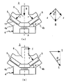
- FIG. 2 is an explanatory diagram of the operation and function of the composite plain bearing shown in FIG. 1, wherein (a) and (b) are a radial load and an axial load acting on the bearing, respectively, and a vector diagram thereof.
- FIG. 2 is a structural cross-sectional view of a main part of a wind turbine generator equipped with the compound plain bearing of FIG. 1 as a main shaft bearing. It is a design structural diagram of a compound slide bearing unit configured by combining a slide bearing for a conventional journal bearing and a slide bearing for a thrust bearing.
- FIG. 1 is a cylindrical hollow fixed shaft (horizontal axis)
- 2 is a rotor center of a generator
- 3 is a compound plain bearing that supports the rotor center 2 on the axis of the fixed shaft 1.
- O in the figure is the axis center of the fixed shaft 1.
- the compound plain bearing 3 is composed of divided rings 4a and 4b which are divided into two at an axial center dividing surface A and are inserted and arranged on the axis of the fixed shaft 1, and have a cross section V on the outer diameter surface thereof.
- An inner ring 4 having a letter-shaped inclined surface, bearing pads 5 distributed on the inclined surfaces of the split rings 4a and 4b along the outer diameter surface of the inner ring 4, and the outer diameter of the inner ring 4
- the bearing pad 5 is formed of an assembly with an outer ring 6 which is formed with an umbrella-shaped inclined surface having a V-shaped cross section corresponding to the surface on the inner diameter surface and attached to the rotor center 2 via a flange 6a.
- the inner peripheral surface of the outer ring 6 is slid on the sliding surface of the bearing pad 5 to support a radial load and an axial load applied to the bearing from the rotor center 2.
- 7 is a bearing pressing ring that holds the inner ring 4 fitted in the fixed shaft 1 in a fixed position
- 8 is a bearing cover that surrounds the peripheral area of the composite slide bearing 3
- 8a is an oil reservoir portion of the lubricating oil 9
- Reference numeral 10 denotes an oil pump for supplying the lubricating oil 9 from the oil reservoir 8a to a so-called lubricating mechanism to be described later.
- the bearing pad 5 is provided on the outside of the inner ring 4 as a tilting pad so as to have a tilting function capable of tilting at least in the rotational direction and, if necessary, in the radial direction.
- the sliding surface is overlaid with white metal or a resin material such as PEEK resin or Teflon (registered trademark) with a low friction coefficient and excellent sliding characteristics (sliding layer) ).
- a metal part having a spring effect or an elastic support seat 11 made of rubber is inserted between the rear surface of the bearing pad 5 and the outer diameter inclined surface of the inner ring 4, and the inner and outer surfaces described above are inserted.
- the bearing load non-uniformity caused by deformation of the rings 4 and 6 is corrected to prevent the bearing load from concentrating on some bearing pads 5.
- the inner ring 4 is provided with a feed oil groove 4c engraved at the center on the inner diameter side along the circumferential direction, and an oil supply hole 4d communicating with the oil supply groove 4c and penetrating through the divided rings 4a and 4b in the radial direction.
- the outer peripheral flange 6a of the outer ring 6 is perforated with an oil passage hole 6b penetrating in the axial direction, and the peripheral surface of the hollow fixed shaft 1 communicates with the oil supply groove 4c.
- the oil filler port 1a is perforated at one place or a plurality of places on the circumference (for example, four places at intervals of 90 °).
- the lubricating oil 9 fed from the oil reservoir 8a through the oil pump 10 is passed through the oil pump 10 through the discharge port of the oil pump 10 and the inner ring through the oil supply port 1a. 4, the lubricating oil 9 flows through the oil supply holes 4 d to the sliding surfaces of the bearing pads 5 installed on the inclined surfaces of the split rings 4 a and 4 b as shown by the arrows in FIG. After lubricating and cooling 5, the oil is recirculated to the oil sump 8 a, where it is sucked up again by the oil pump 10 and circulated and supplied to the bearings.
- the radial load R and the axial load are applied to the composite slide bearing rod 3 with the rotor and wind turbine of the generator supported on the fixed shaft 1 (horizontal axis) via the composite slide bearing 3.
- the radial load R acts on the two rows of bearing pads 5 arranged on the V-shaped inclined surface of the inner ring 4 (see FIG. 2A), and the axial load T
- the component force t is supported and supported by the bearing pad 5 corresponding to the direction of the load (see FIG. 2B).
- the inclined surface angle (contact angle) ⁇ of the inner ring 4 shown in the figure is the resultant force (total load) of the component force r of the radial load acting on the bearing pad 5 and the component force t of the axial load. Select so that is minimized.
- the heel contact angle of the outer ring 6 is basically set to be the same as the angle ⁇ of the inner ring 4, but the contact angle may be slightly changed in consideration of the deformation amount of the inner ring 4.
- the inner ring 4 is a fixed ring attached to the fixed shaft 1 and the outer ring 6 is a rotating ring to form a bearing for the main shaft.
- the ring 4 can be used as a rotating ring and the outer ring 6 can be used as a saddle fixing ring to support the main shaft.
- the split rings 4a and 4b of the inner ring 4 are overlapped in the axial direction, but a spacer may be interposed between the split rings 4a and 4b as necessary.
- FIG. 3 shows an embodiment of a wind power generator by a direct drive system in which the above-described compound plain bearing is adopted as a main shaft bearing of a generator.
- 12 is a generator (permanent magnet type synchronous generator)
- 13 is a rotor hub of a windmill directly connected to the front of the rotor shaft of the generator 12
- 14 is a top of the tower via a yaw drive (not shown).
- the mounted rotor 15 and the rotor of the generator and the windmill are fixed shafts 15 (cylindrical hollow fixed in FIG. 1) provided on the front of the nacelle 14 through the composite plain bearing 3 of the present invention described in FIG. (Corresponding to the shaft 1) is rotatably supported on the shaft.
- 12a is a stator core of the generator 12
- 12b is a rotor core
- 12c is a rotor magnetic pole (permanent magnets arranged on the circumference of the rotor core)
- 12d is a generator frame of the stator 12a
- 12e is This is a rotor center (corresponding to the rotor center 2 in FIG. 1) that supports the rotor core 12b.
- the generator frame 12d of the stator 12 is fixed to the front part of the nacelle 14 and in front of the rotor center 12e.
- the wind turbine rotor hub 13 is connected to support the impeller in an overhanging state.
- the compound plain bearing 3 is installed between the fixed shaft 15 and the rotor center 12e of the generator 12, and rotatably supports the wind turbine and the generator rotor.
- the wind power generator of FIG. 3 is designed so that the ratio of the length to the generator diameter is about 20% in order to increase the peripheral diameter of the generator 12 and to shorten the shaft length so as to increase the peripheral speed.
- the rotor of the generator and the windmill are supported by the single composite sliding bearing 3 on the fixed shaft 15 so as to support the radial load and the axial load (wind turbine wind load) that are applied during operation. .
- the rotor assembly of the generator 12 is preliminarily fixed to a jig (not shown). It is temporarily fixed to the inner side of the stator 12a using a tool.
- a bearing pad 5 is previously attached to the inner ring 4 of the composite plain bearing 3 (refer to FIG. 1 for the detailed structure).
- the split ring 4b on the nacelle side of the inner ring is inserted into the shaft peripheral surface from the distal end side of the fixed shaft 15, and the split ring 4b is pressed against the shoulder 1b (see FIG. 1) to be positioned at a predetermined position. To do.
- the outer ring 6 is assembled on the inner peripheral side of the split ring 4 b and superimposed on the sliding surface of the bearing pad 5, and the outer peripheral flange 6 a of the outer ring 6 is coupled to the rotor center 12 e of the generator 12.
- the other split ring 4a of the inner ring 4 is inserted into the peripheral surface of the fixed shaft 15, the bearing pad 5 is superimposed on the umbrella-shaped inclined surface of the outer ring 6, and finally the bearing retainer ring 7 is split.
- the bearing is fixed in place by pressing against the end face of the ring 4a.
- the jig for temporarily fixing the rotor of the generator 12 is removed to complete the assembly of the composite slide bearing 3 and the rotor of the generator 12, and then the rotor hub rod 13 of the windmill is attached to the rotor center 12e. Connect to the front.
- the composite slide bearing 3 can be disassembled and removed in the reverse order of the assembly procedure, which contributes to the maintenance of the bearing.
- it is extremely difficult to replace bearing parts at a high place on the tower with the current wind power generation equipment in which rolling bearings are used for the main shaft bearings. Nearly impossible.
- the bearing holding ring 7 is then removed, and then the split ring 4a is pulled out from the fixed shaft 15 by using a hanging and pulling jig, and the replacement work of the bearing pad 5 is moved to a position where it can be changed to a new position. Replace with bearing pad.
Landscapes
- Engineering & Computer Science (AREA)
- General Engineering & Computer Science (AREA)
- Mechanical Engineering (AREA)
- Chemical & Material Sciences (AREA)
- Oil, Petroleum & Natural Gas (AREA)
- Life Sciences & Earth Sciences (AREA)
- Sustainable Development (AREA)
- Sustainable Energy (AREA)
- Combustion & Propulsion (AREA)
- Wind Motors (AREA)
- Sliding-Contact Bearings (AREA)
- Support Of The Bearing (AREA)
Abstract
Le problème à résoudre dans le cadre de la présente invention est de proposer, en tant que palier d'arbre principal pour un dispositif générateur d'électricité éolien, un palier coulissant composite qui supporte de façon stable une charge radiale et une charge axiale avec une construction compacte, et possède une excellente facilité de maintenance. La solution proposée consiste en un palier coulissant composite (3) qui est formé au moyen : d'une bague intérieure (4), qui comprend deux bagues fendues (4a, 4b) qui sont divisées au centre dans le sens axial, avec une surface inclinée qui présente une section transversale en forme de V formée dans sa surface diamétrale extérieure ; de patins de palier (5) agencés de façon distribuée sur la surface inclinée des bagues fendues (4a, 4b) le long de la surface diamétrale extérieure de la bague intérieure (4) ; et d'une bague extérieure (6), sur la surface diamétrale intérieure de laquelle est formée une surface inclinée en forme de parapluie qui présente une section transversale en forme de V et qui correspond à la surface diamétrale extérieure de la bague intérieure (4). Lorsque les patins de palier (5) sont lubrifiés, la surface diamétrale intérieure de la bague extérieure (6) coulisse sur la surface de coulissement des patins de palier, supportant ainsi la charge radiale et la charge axiale appliquées sur le palier (3).
Priority Applications (4)
| Application Number | Priority Date | Filing Date | Title |
|---|---|---|---|
| DK13807065.1T DK2863076T3 (da) | 2012-06-19 | 2013-06-18 | Komposit-glideleje og vinddrevet strømforsyningsapparat med anvendelse af dette leje |
| EP13807065.1A EP2863076B1 (fr) | 2012-06-19 | 2013-06-18 | Palier coulissant composite et dispositif générateur d'électricité éolien qui utilise ledit palier coulissant composite |
| JP2014521472A JP5880707B2 (ja) | 2012-06-19 | 2013-06-18 | 複合すべり軸受およびこの軸受けを用いた風力発電装置 |
| US14/477,141 US10072704B2 (en) | 2012-06-19 | 2014-09-04 | Composite sliding bearing and wind power generating device using the same bearing |
Applications Claiming Priority (2)
| Application Number | Priority Date | Filing Date | Title |
|---|---|---|---|
| JP2012138017 | 2012-06-19 | ||
| JP2012-138017 | 2012-06-19 |
Related Child Applications (1)
| Application Number | Title | Priority Date | Filing Date |
|---|---|---|---|
| US14/477,141 Continuation US10072704B2 (en) | 2012-06-19 | 2014-09-04 | Composite sliding bearing and wind power generating device using the same bearing |
Publications (1)
| Publication Number | Publication Date |
|---|---|
| WO2013191163A1 true WO2013191163A1 (fr) | 2013-12-27 |
Family
ID=49768759
Family Applications (1)
| Application Number | Title | Priority Date | Filing Date |
|---|---|---|---|
| PCT/JP2013/066677 Ceased WO2013191163A1 (fr) | 2012-06-19 | 2013-06-18 | Palier coulissant composite et dispositif générateur d'électricité éolien qui utilise ledit palier coulissant composite |
Country Status (5)
| Country | Link |
|---|---|
| US (1) | US10072704B2 (fr) |
| EP (1) | EP2863076B1 (fr) |
| JP (1) | JP5880707B2 (fr) |
| DK (1) | DK2863076T3 (fr) |
| WO (1) | WO2013191163A1 (fr) |
Cited By (14)
| Publication number | Priority date | Publication date | Assignee | Title |
|---|---|---|---|---|
| CN109296630A (zh) * | 2018-12-04 | 2019-02-01 | 四川宏华石油设备有限公司 | 一种径向滑动轴承 |
| JP2019516908A (ja) * | 2016-05-27 | 2019-06-20 | ヴォッベン プロパティーズ ゲーエムベーハー | 風力発電設備 |
| JP2019534428A (ja) * | 2016-10-21 | 2019-11-28 | ミバ・グライトラーガー・オーストリア・ゲゼルシャフト・ミト・ベシュレンクテル・ハフツング | 軸受部材 |
| JP2021148287A (ja) * | 2020-03-18 | 2021-09-27 | 隆志 浜口 | ベアリングの取り付け方法。 |
| JP2022510477A (ja) * | 2018-12-13 | 2022-01-26 | ミバ・グライトラーガー・オーストリア・ゲゼルシャフト・ミト・ベシュレンクテル・ハフツング | 風力発電機用ナセル |
| JP2022510702A (ja) * | 2018-12-13 | 2022-01-27 | ミバ・グライトラーガー・オーストリア・ゲゼルシャフト・ミト・ベシュレンクテル・ハフツング | 風力発電機用ナセル |
| JP2022513175A (ja) * | 2018-12-13 | 2022-02-07 | ミバ・グライトラーガー・オーストリア・ゲゼルシャフト・ミト・ベシュレンクテル・ハフツング | 風力タービン用のナセル |
| KR20220124204A (ko) * | 2020-01-08 | 2022-09-13 | 베스타스 윈드 시스템스 에이/에스 | 풍력 터빈의 메인 베어링 하우징 |
| US11493019B2 (en) | 2016-06-07 | 2022-11-08 | Wobben Properties Gmbh | Wind turbine rotary connection, rotor blade, and wind turbine comprising same |
| JP2023523751A (ja) * | 2020-04-28 | 2023-06-07 | シーメンス ガメサ リニューアブル エナジー エー/エス | 特に風力タービンのロータハブ用の流体膜軸受 |
| US11761429B2 (en) | 2018-12-13 | 2023-09-19 | Miba Gleitlager Austria Gmbh | Slide bearing, in particular for a gearbox of a wind turbine |
| US11808247B2 (en) | 2018-12-13 | 2023-11-07 | Miba Gleitlager Austria Gmbh | Planetary gear set for a wind turbine |
| JP2023551036A (ja) * | 2020-11-30 | 2023-12-06 | ミバ・グライトラーガー・オーストリア・ゲゼルシャフト・ミト・ベシュレンクテル・ハフツング | 風力タービンのロータ軸受を組み立てるための方法 |
| US11940006B2 (en) | 2018-12-13 | 2024-03-26 | Miba Gleitlager Austria Gmbh | Method for changing a sliding bearing element of a rotor bearing of a wind turbine, and nacelle for a wind turbine |
Families Citing this family (28)
| Publication number | Priority date | Publication date | Assignee | Title |
|---|---|---|---|---|
| EP2657519B1 (fr) * | 2012-04-26 | 2015-06-17 | Siemens Aktiengesellschaft | Éolienne |
| US9909450B1 (en) | 2013-03-13 | 2018-03-06 | Us Synthetic Corporation | Turbine assembly including at least one superhard bearing |
| US10318848B2 (en) * | 2015-12-15 | 2019-06-11 | Qualcomm Incorporated | Methods for object localization and image classification |
| DK3219984T3 (en) | 2016-03-14 | 2019-04-08 | Siemens Ag | Sliding bearing assembly for a wind turbine |
| DE102016114678A1 (de) * | 2016-08-08 | 2018-02-08 | Thyssenkrupp Ag | Drehlageranordnung für eine Lenksäule eines Kraftfahrzeugs |
| JP2020517506A (ja) * | 2017-04-21 | 2020-06-18 | サン−ゴバン パフォーマンス プラスティックス レンコール リミティド | 調整可能なジョイントアセンブリ |
| DE102017114584A1 (de) * | 2017-06-29 | 2019-01-03 | Wobben Properties Gmbh | Windenergieanlagen-Drehverbindung, und Windenergieanlage mit selbiger |
| US10385830B2 (en) | 2017-07-14 | 2019-08-20 | General Electric Company | Compound main bearing arrangement for a wind turbine |
| DE102017006957A1 (de) | 2017-07-25 | 2019-01-31 | Rheinisch-Westfälische Technische Hochschule (Rwth) Aachen | Gleitlagervorrichtung |
| CN108556562B (zh) * | 2018-03-23 | 2024-03-12 | 中信戴卡股份有限公司 | 一种用于控制轮毂温度的装置 |
| DE102018120806A1 (de) * | 2018-08-27 | 2020-02-27 | Renk Aktiengesellschaft | Lageranordnung eines Rotors einer Windkraftanlage |
| DE102018120810A1 (de) * | 2018-08-27 | 2020-02-27 | Renk Aktiengesellschaft | Lageranordnung eines Rotors einer Windkraftanlage und Windkraftanlage |
| AT522155B1 (de) * | 2019-03-07 | 2020-09-15 | Miba Gleitlager Austria Gmbh | Gleitlagerung |
| AT522164B1 (de) | 2019-03-07 | 2020-09-15 | Miba Gleitlager Austria Gmbh | Gleitlagerung |
| CN110056487A (zh) * | 2019-03-14 | 2019-07-26 | 远景能源(江苏)有限公司 | 一种用于风力发电机的滑动式轴承及其维护方法 |
| US11174895B2 (en) * | 2019-04-30 | 2021-11-16 | General Electric Company | Bearing for a wind turbine drivetrain having an elastomer support |
| EP3739226B1 (fr) * | 2019-05-16 | 2022-12-14 | Siemens Gamesa Renewable Energy A/S | Agencement de palier d'une éolienne et éolienne |
| AT522476B1 (de) | 2019-05-21 | 2020-11-15 | Miba Gleitlager Austria Gmbh | Gondel für eine Windkraftanlage |
| EP3767118B1 (fr) * | 2019-07-19 | 2022-11-23 | Siemens Gamesa Renewable Energy A/S | Palier de pas de pale de rotor d'éolienne |
| US12049873B2 (en) | 2020-01-08 | 2024-07-30 | Vestas Wind Systems A/S | Main bearing housing of a wind turbine |
| EP3904669A1 (fr) * | 2020-04-28 | 2021-11-03 | Siemens Gamesa Renewable Energy A/S | Éolienne |
| EP4047228A1 (fr) * | 2021-02-23 | 2022-08-24 | Flender GmbH | Agencement des roulements, pignon de générateur, centrale éolienne et produit programme informatique |
| FR3123885B1 (fr) * | 2021-06-15 | 2023-06-16 | Safran Aircraft Engines | Redresseur non carene de turbomachine equipe d’aubes de stator fixees a des pivots et turbomachine correspondante |
| WO2023123506A1 (fr) * | 2021-12-31 | 2023-07-06 | 湖南崇德科技股份有限公司 | Ensemble palier pour éolienne |
| CN114321157B (zh) * | 2021-12-31 | 2024-08-13 | 湖南崇德科技股份有限公司 | 一种风力发电机用轴承组件 |
| FR3132123B1 (fr) * | 2022-01-21 | 2023-12-08 | Safran Aircraft Engines | Aube de redresseur de flux secondaire de turbomachine, turbomachine munie de celle-ci |
| CN114278522B (zh) * | 2022-01-25 | 2023-05-12 | 北京三力新能科技有限公司 | 一种框架式轴承座 |
| CN118309780A (zh) * | 2022-12-30 | 2024-07-09 | 金风科技股份有限公司 | 传动系统及风力发电机组 |
Citations (11)
| Publication number | Priority date | Publication date | Assignee | Title |
|---|---|---|---|---|
| JPS5842420U (ja) * | 1981-09-16 | 1983-03-22 | オリジン電気株式会社 | すべり軸受 |
| JPH048915A (ja) * | 1990-04-27 | 1992-01-13 | Hitachi Ltd | ラジアルスラスト軸受および組立て方法 |
| JPH08177711A (ja) | 1994-12-22 | 1996-07-12 | Mitsubishi Heavy Ind Ltd | 大容量風力発電用増速機 |
| JP2005105917A (ja) | 2003-09-30 | 2005-04-21 | Mitsubishi Heavy Ind Ltd | 風力発電用風車 |
| JP2006118552A (ja) * | 2004-10-20 | 2006-05-11 | Mitsubishi Heavy Ind Ltd | 軸受装置 |
| JP2009019625A (ja) | 2007-07-10 | 2009-01-29 | Siemens Ag | 風力タービンとその取付け法及び風力タービンの発電機の回転子と固定子との空隙の調整方法 |
| JP2010116959A (ja) * | 2008-11-12 | 2010-05-27 | Mitsubishi Heavy Ind Ltd | ジャーナル軸受を備えた回転構造体 |
| WO2011003482A2 (fr) * | 2009-07-10 | 2011-01-13 | Siemens Aktiengesellschaft | Palier principal déolienne |
| WO2011033256A1 (fr) * | 2009-09-15 | 2011-03-24 | Ricardo Uk Ltd. | Palier pour éolienne |
| JP2011064141A (ja) | 2009-09-17 | 2011-03-31 | Fuji Electric Systems Co Ltd | 風力発電装置 |
| JP2011140983A (ja) * | 2010-01-07 | 2011-07-21 | Yogo Giken:Kk | 流体軸受装置 |
Family Cites Families (6)
| Publication number | Priority date | Publication date | Assignee | Title |
|---|---|---|---|---|
| FR2415747A1 (fr) * | 1978-01-25 | 1979-08-24 | Greene Jerome | Palier hydrodynamique encaissant les charges radiales et axiales et les couples transversaux |
| US4243274A (en) * | 1978-08-28 | 1981-01-06 | Jerome Greene | Hydrodynamic bearing with radial, thrust and moment load capacity |
| CN101981332B (zh) * | 2008-11-12 | 2013-03-20 | 三菱重工业株式会社 | 轴颈轴承的旋转轴支承结构和该轴承的组装方法 |
| AT509625B1 (de) * | 2010-04-14 | 2012-02-15 | Miba Gleitlager Gmbh | Lagerelement |
| EP2568168A1 (fr) * | 2011-09-08 | 2013-03-13 | Siemens Aktiengesellschaft | Éolienne à commande directe |
| EP2657519B1 (fr) * | 2012-04-26 | 2015-06-17 | Siemens Aktiengesellschaft | Éolienne |
-
2013
- 2013-06-18 WO PCT/JP2013/066677 patent/WO2013191163A1/fr not_active Ceased
- 2013-06-18 EP EP13807065.1A patent/EP2863076B1/fr active Active
- 2013-06-18 DK DK13807065.1T patent/DK2863076T3/da active
- 2013-06-18 JP JP2014521472A patent/JP5880707B2/ja active Active
-
2014
- 2014-09-04 US US14/477,141 patent/US10072704B2/en active Active
Patent Citations (11)
| Publication number | Priority date | Publication date | Assignee | Title |
|---|---|---|---|---|
| JPS5842420U (ja) * | 1981-09-16 | 1983-03-22 | オリジン電気株式会社 | すべり軸受 |
| JPH048915A (ja) * | 1990-04-27 | 1992-01-13 | Hitachi Ltd | ラジアルスラスト軸受および組立て方法 |
| JPH08177711A (ja) | 1994-12-22 | 1996-07-12 | Mitsubishi Heavy Ind Ltd | 大容量風力発電用増速機 |
| JP2005105917A (ja) | 2003-09-30 | 2005-04-21 | Mitsubishi Heavy Ind Ltd | 風力発電用風車 |
| JP2006118552A (ja) * | 2004-10-20 | 2006-05-11 | Mitsubishi Heavy Ind Ltd | 軸受装置 |
| JP2009019625A (ja) | 2007-07-10 | 2009-01-29 | Siemens Ag | 風力タービンとその取付け法及び風力タービンの発電機の回転子と固定子との空隙の調整方法 |
| JP2010116959A (ja) * | 2008-11-12 | 2010-05-27 | Mitsubishi Heavy Ind Ltd | ジャーナル軸受を備えた回転構造体 |
| WO2011003482A2 (fr) * | 2009-07-10 | 2011-01-13 | Siemens Aktiengesellschaft | Palier principal déolienne |
| WO2011033256A1 (fr) * | 2009-09-15 | 2011-03-24 | Ricardo Uk Ltd. | Palier pour éolienne |
| JP2011064141A (ja) | 2009-09-17 | 2011-03-31 | Fuji Electric Systems Co Ltd | 風力発電装置 |
| JP2011140983A (ja) * | 2010-01-07 | 2011-07-21 | Yogo Giken:Kk | 流体軸受装置 |
Non-Patent Citations (1)
| Title |
|---|
| See also references of EP2863076A4 |
Cited By (25)
| Publication number | Priority date | Publication date | Assignee | Title |
|---|---|---|---|---|
| JP2019516908A (ja) * | 2016-05-27 | 2019-06-20 | ヴォッベン プロパティーズ ゲーエムベーハー | 風力発電設備 |
| US10669997B2 (en) | 2016-05-27 | 2020-06-02 | Wobben Properties Gmbh | Wind turbine |
| US11493019B2 (en) | 2016-06-07 | 2022-11-08 | Wobben Properties Gmbh | Wind turbine rotary connection, rotor blade, and wind turbine comprising same |
| JP2019534428A (ja) * | 2016-10-21 | 2019-11-28 | ミバ・グライトラーガー・オーストリア・ゲゼルシャフト・ミト・ベシュレンクテル・ハフツング | 軸受部材 |
| CN109296630B (zh) * | 2018-12-04 | 2023-09-12 | 四川宏华石油设备有限公司 | 一种径向滑动轴承 |
| CN109296630A (zh) * | 2018-12-04 | 2019-02-01 | 四川宏华石油设备有限公司 | 一种径向滑动轴承 |
| JP7196307B2 (ja) | 2018-12-13 | 2022-12-26 | ミバ・グライトラーガー・オーストリア・ゲゼルシャフト・ミト・ベシュレンクテル・ハフツング | 風力発電機用ナセル |
| US11940006B2 (en) | 2018-12-13 | 2024-03-26 | Miba Gleitlager Austria Gmbh | Method for changing a sliding bearing element of a rotor bearing of a wind turbine, and nacelle for a wind turbine |
| US12196184B2 (en) | 2018-12-13 | 2025-01-14 | Miba Gleitlager Austria Gmbh | Nacelle for a wind turbine |
| JP7139530B2 (ja) | 2018-12-13 | 2022-09-20 | ミバ・グライトラーガー・オーストリア・ゲゼルシャフト・ミト・ベシュレンクテル・ハフツング | 風力タービン用のナセル |
| JP2022510702A (ja) * | 2018-12-13 | 2022-01-27 | ミバ・グライトラーガー・オーストリア・ゲゼルシャフト・ミト・ベシュレンクテル・ハフツング | 風力発電機用ナセル |
| JP7185781B2 (ja) | 2018-12-13 | 2022-12-07 | ミバ・グライトラーガー・オーストリア・ゲゼルシャフト・ミト・ベシュレンクテル・ハフツング | 風力発電機用ナセル |
| JP2022510477A (ja) * | 2018-12-13 | 2022-01-26 | ミバ・グライトラーガー・オーストリア・ゲゼルシャフト・ミト・ベシュレンクテル・ハフツング | 風力発電機用ナセル |
| US12110874B2 (en) | 2018-12-13 | 2024-10-08 | Miba Gleitlager Austria Gmbh | Nacelle for a wind turbine |
| US11746757B2 (en) | 2018-12-13 | 2023-09-05 | Miba Gleitlager Austria Gmbh | Nacelle for a wind turbine |
| JP2022513175A (ja) * | 2018-12-13 | 2022-02-07 | ミバ・グライトラーガー・オーストリア・ゲゼルシャフト・ミト・ベシュレンクテル・ハフツング | 風力タービン用のナセル |
| US11761429B2 (en) | 2018-12-13 | 2023-09-19 | Miba Gleitlager Austria Gmbh | Slide bearing, in particular for a gearbox of a wind turbine |
| US11808247B2 (en) | 2018-12-13 | 2023-11-07 | Miba Gleitlager Austria Gmbh | Planetary gear set for a wind turbine |
| KR20220124204A (ko) * | 2020-01-08 | 2022-09-13 | 베스타스 윈드 시스템스 에이/에스 | 풍력 터빈의 메인 베어링 하우징 |
| KR102867374B1 (ko) | 2020-01-08 | 2025-09-30 | 베스타스 윈드 시스템스 에이/에스 | 풍력 터빈의 메인 베어링 하우징 |
| JP2021148287A (ja) * | 2020-03-18 | 2021-09-27 | 隆志 浜口 | ベアリングの取り付け方法。 |
| JP7538248B2 (ja) | 2020-04-28 | 2024-08-21 | シーメンス ガメサ リニューアブル エナジー エー/エス | 特に風力タービンのロータハブ用の流体膜軸受 |
| JP2023523751A (ja) * | 2020-04-28 | 2023-06-07 | シーメンス ガメサ リニューアブル エナジー エー/エス | 特に風力タービンのロータハブ用の流体膜軸受 |
| US12313041B2 (en) | 2020-04-28 | 2025-05-27 | Siemens Gamesa Renewable Energy A/S | Fluid film bearing, especially for a rotor hub in a wind turbine |
| JP2023551036A (ja) * | 2020-11-30 | 2023-12-06 | ミバ・グライトラーガー・オーストリア・ゲゼルシャフト・ミト・ベシュレンクテル・ハフツング | 風力タービンのロータ軸受を組み立てるための方法 |
Also Published As
| Publication number | Publication date |
|---|---|
| JP5880707B2 (ja) | 2016-03-09 |
| JPWO2013191163A1 (ja) | 2016-05-26 |
| DK2863076T3 (da) | 2021-05-25 |
| EP2863076A4 (fr) | 2016-02-24 |
| EP2863076A1 (fr) | 2015-04-22 |
| EP2863076B1 (fr) | 2021-02-24 |
| US20150017000A1 (en) | 2015-01-15 |
| US10072704B2 (en) | 2018-09-11 |
Similar Documents
| Publication | Publication Date | Title |
|---|---|---|
| JP5880707B2 (ja) | 複合すべり軸受およびこの軸受けを用いた風力発電装置 | |
| CN102834611B (zh) | 支承元件 | |
| CN104632880B (zh) | 用于流体机械应用的轴承装置 | |
| EP3460238B1 (fr) | Éolienne | |
| US10788018B2 (en) | Wind turbine rotor shaft arrangement | |
| CN103782028B (zh) | 直接驱动风力涡轮机 | |
| CN105464897B (zh) | 风轮机转子轴设备 | |
| CN104632879B (zh) | 用于流体机械应用的轴承单元 | |
| US10385830B2 (en) | Compound main bearing arrangement for a wind turbine | |
| CN102418740A (zh) | 三排滚子轴承,特别是用于风力涡轮机的三排滚子轴承 | |
| US20110236186A1 (en) | Wind turbine and a pitch bearing for a wind turbine | |
| US10197093B2 (en) | Bearing arrangement | |
| US10458469B2 (en) | Bearing unit | |
| US20200102939A1 (en) | Bearing arrangement for a wind turbine, wind turbine and method for manufacturing a wind turbine | |
| CN113446173A (zh) | 风力发电机组及其传动轴系 | |
| CN105508155A (zh) | 风力发电机组 | |
| US8167495B2 (en) | Device comprising a support structure and a rotating shaft and wind turbine | |
| WO2015022311A1 (fr) | Système de paliers comprenant des paliers sphériques radial et de butée | |
| JP5932058B2 (ja) | 風力発電装置 | |
| JP2017057952A (ja) | 複列自動調心ころ軸受 | |
| JP2007132418A (ja) | 風力発電機主軸支持構造 | |
| WO2015057126A1 (fr) | Agencement de palier de rotor de turbine éolienne | |
| KR101024361B1 (ko) | 스러스트베어링 | |
| JP2006090346A (ja) | 複列自動調心ころ軸受および風力発電機の主軸支持構造 |
Legal Events
| Date | Code | Title | Description |
|---|---|---|---|
| 121 | Ep: the epo has been informed by wipo that ep was designated in this application |
Ref document number: 13807065 Country of ref document: EP Kind code of ref document: A1 |
|
| ENP | Entry into the national phase |
Ref document number: 2014521472 Country of ref document: JP Kind code of ref document: A |
|
| NENP | Non-entry into the national phase |
Ref country code: DE |