WO2013191165A1 - 観察撮影装置 - Google Patents
観察撮影装置 Download PDFInfo
- Publication number
- WO2013191165A1 WO2013191165A1 PCT/JP2013/066684 JP2013066684W WO2013191165A1 WO 2013191165 A1 WO2013191165 A1 WO 2013191165A1 JP 2013066684 W JP2013066684 W JP 2013066684W WO 2013191165 A1 WO2013191165 A1 WO 2013191165A1
- Authority
- WO
- WIPO (PCT)
- Prior art keywords
- polishing
- observation
- sample
- cloth
- microscope
- Prior art date
- Legal status (The legal status is an assumption and is not a legal conclusion. Google has not performed a legal analysis and makes no representation as to the accuracy of the status listed.)
- Ceased
Links
Images




Classifications
-
- B—PERFORMING OPERATIONS; TRANSPORTING
- B24—GRINDING; POLISHING
- B24B—MACHINES, DEVICES, OR PROCESSES FOR GRINDING OR POLISHING; DRESSING OR CONDITIONING OF ABRADING SURFACES; FEEDING OF GRINDING, POLISHING, OR LAPPING AGENTS
- B24B37/00—Lapping machines or devices; Accessories
- B24B37/04—Lapping machines or devices; Accessories designed for working plane surfaces
- B24B37/07—Lapping machines or devices; Accessories designed for working plane surfaces characterised by the movement of the work or lapping tool
- B24B37/10—Lapping machines or devices; Accessories designed for working plane surfaces characterised by the movement of the work or lapping tool for single side lapping
-
- G—PHYSICS
- G02—OPTICS
- G02B—OPTICAL ELEMENTS, SYSTEMS OR APPARATUS
- G02B21/00—Microscopes
-
- G—PHYSICS
- G01—MEASURING; TESTING
- G01N—INVESTIGATING OR ANALYSING MATERIALS BY DETERMINING THEIR CHEMICAL OR PHYSICAL PROPERTIES
- G01N1/00—Sampling; Preparing specimens for investigation
- G01N1/28—Preparing specimens for investigation including physical details of (bio-)chemical methods covered elsewhere, e.g. G01N33/50, C12Q
- G01N1/32—Polishing; Etching
-
- B—PERFORMING OPERATIONS; TRANSPORTING
- B23—MACHINE TOOLS; METAL-WORKING NOT OTHERWISE PROVIDED FOR
- B23H—WORKING OF METAL BY THE ACTION OF A HIGH CONCENTRATION OF ELECTRIC CURRENT ON A WORKPIECE USING AN ELECTRODE WHICH TAKES THE PLACE OF A TOOL; SUCH WORKING COMBINED WITH OTHER FORMS OF WORKING OF METAL
- B23H5/00—Combined machining
- B23H5/06—Electrochemical machining combined with mechanical working, e.g. grinding or honing
-
- B—PERFORMING OPERATIONS; TRANSPORTING
- B23—MACHINE TOOLS; METAL-WORKING NOT OTHERWISE PROVIDED FOR
- B23H—WORKING OF METAL BY THE ACTION OF A HIGH CONCENTRATION OF ELECTRIC CURRENT ON A WORKPIECE USING AN ELECTRODE WHICH TAKES THE PLACE OF A TOOL; SUCH WORKING COMBINED WITH OTHER FORMS OF WORKING OF METAL
- B23H5/00—Combined machining
- B23H5/06—Electrochemical machining combined with mechanical working, e.g. grinding or honing
- B23H5/08—Electrolytic grinding
-
- B—PERFORMING OPERATIONS; TRANSPORTING
- B24—GRINDING; POLISHING
- B24B—MACHINES, DEVICES, OR PROCESSES FOR GRINDING OR POLISHING; DRESSING OR CONDITIONING OF ABRADING SURFACES; FEEDING OF GRINDING, POLISHING, OR LAPPING AGENTS
- B24B37/00—Lapping machines or devices; Accessories
-
- B—PERFORMING OPERATIONS; TRANSPORTING
- B24—GRINDING; POLISHING
- B24B—MACHINES, DEVICES, OR PROCESSES FOR GRINDING OR POLISHING; DRESSING OR CONDITIONING OF ABRADING SURFACES; FEEDING OF GRINDING, POLISHING, OR LAPPING AGENTS
- B24B37/00—Lapping machines or devices; Accessories
- B24B37/04—Lapping machines or devices; Accessories designed for working plane surfaces
- B24B37/046—Lapping machines or devices; Accessories designed for working plane surfaces using electric current
-
- B—PERFORMING OPERATIONS; TRANSPORTING
- B24—GRINDING; POLISHING
- B24B—MACHINES, DEVICES, OR PROCESSES FOR GRINDING OR POLISHING; DRESSING OR CONDITIONING OF ABRADING SURFACES; FEEDING OF GRINDING, POLISHING, OR LAPPING AGENTS
- B24B37/00—Lapping machines or devices; Accessories
- B24B37/11—Lapping tools
- B24B37/20—Lapping pads for working plane surfaces
- B24B37/24—Lapping pads for working plane surfaces characterised by the composition or properties of the pad materials
-
- B—PERFORMING OPERATIONS; TRANSPORTING
- B24—GRINDING; POLISHING
- B24B—MACHINES, DEVICES, OR PROCESSES FOR GRINDING OR POLISHING; DRESSING OR CONDITIONING OF ABRADING SURFACES; FEEDING OF GRINDING, POLISHING, OR LAPPING AGENTS
- B24B37/00—Lapping machines or devices; Accessories
- B24B37/11—Lapping tools
- B24B37/20—Lapping pads for working plane surfaces
- B24B37/26—Lapping pads for working plane surfaces characterised by the shape of the lapping pad surface, e.g. grooved
-
- B—PERFORMING OPERATIONS; TRANSPORTING
- B24—GRINDING; POLISHING
- B24B—MACHINES, DEVICES, OR PROCESSES FOR GRINDING OR POLISHING; DRESSING OR CONDITIONING OF ABRADING SURFACES; FEEDING OF GRINDING, POLISHING, OR LAPPING AGENTS
- B24B37/00—Lapping machines or devices; Accessories
- B24B37/34—Accessories
- B24B37/345—Feeding, loading or unloading work specially adapted to lapping
-
- B—PERFORMING OPERATIONS; TRANSPORTING
- B24—GRINDING; POLISHING
- B24B—MACHINES, DEVICES, OR PROCESSES FOR GRINDING OR POLISHING; DRESSING OR CONDITIONING OF ABRADING SURFACES; FEEDING OF GRINDING, POLISHING, OR LAPPING AGENTS
- B24B49/00—Measuring or gauging equipment for controlling the feed movement of the grinding tool or work; Arrangements of indicating or measuring equipment, e.g. for indicating the start of the grinding operation
- B24B49/12—Measuring or gauging equipment for controlling the feed movement of the grinding tool or work; Arrangements of indicating or measuring equipment, e.g. for indicating the start of the grinding operation involving optical means
-
- B—PERFORMING OPERATIONS; TRANSPORTING
- B24—GRINDING; POLISHING
- B24B—MACHINES, DEVICES, OR PROCESSES FOR GRINDING OR POLISHING; DRESSING OR CONDITIONING OF ABRADING SURFACES; FEEDING OF GRINDING, POLISHING, OR LAPPING AGENTS
- B24B57/00—Devices for feeding, applying, grading or recovering grinding, polishing or lapping agents
- B24B57/02—Devices for feeding, applying, grading or recovering grinding, polishing or lapping agents for feeding of fluid, sprayed, pulverised, or liquefied grinding, polishing or lapping agents
-
- C—CHEMISTRY; METALLURGY
- C25—ELECTROLYTIC OR ELECTROPHORETIC PROCESSES; APPARATUS THEREFOR
- C25F—PROCESSES FOR THE ELECTROLYTIC REMOVAL OF MATERIALS FROM OBJECTS; APPARATUS THEREFOR
- C25F3/00—Electrolytic etching or polishing
-
- C—CHEMISTRY; METALLURGY
- C25—ELECTROLYTIC OR ELECTROPHORETIC PROCESSES; APPARATUS THEREFOR
- C25F—PROCESSES FOR THE ELECTROLYTIC REMOVAL OF MATERIALS FROM OBJECTS; APPARATUS THEREFOR
- C25F3/00—Electrolytic etching or polishing
- C25F3/16—Polishing
-
- C—CHEMISTRY; METALLURGY
- C25—ELECTROLYTIC OR ELECTROPHORETIC PROCESSES; APPARATUS THEREFOR
- C25F—PROCESSES FOR THE ELECTROLYTIC REMOVAL OF MATERIALS FROM OBJECTS; APPARATUS THEREFOR
- C25F7/00—Constructional parts, or assemblies thereof, of cells for electrolytic removal of material from objects; Servicing or operating
-
- G—PHYSICS
- G02—OPTICS
- G02B—OPTICAL ELEMENTS, SYSTEMS OR APPARATUS
- G02B21/00—Microscopes
- G02B21/24—Base structure
- G02B21/26—Stages; Adjusting means therefor
-
- G—PHYSICS
- G02—OPTICS
- G02B—OPTICAL ELEMENTS, SYSTEMS OR APPARATUS
- G02B21/00—Microscopes
- G02B21/36—Microscopes arranged for photographic purposes or projection purposes or digital imaging or video purposes including associated control and data processing arrangements
- G02B21/365—Control or image processing arrangements for digital or video microscopes
- G02B21/367—Control or image processing arrangements for digital or video microscopes providing an output produced by processing a plurality of individual source images, e.g. image tiling, montage, composite images, depth sectioning, image comparison
-
- H—ELECTRICITY
- H10—SEMICONDUCTOR DEVICES; ELECTRIC SOLID-STATE DEVICES NOT OTHERWISE PROVIDED FOR
- H10P—GENERIC PROCESSES OR APPARATUS FOR THE MANUFACTURE OR TREATMENT OF DEVICES COVERED BY CLASS H10
- H10P50/00—Etching of wafers, substrates or parts of devices
- H10P50/60—Wet etching
- H10P50/61—Electrolytic etching
- H10P50/613—Electrolytic etching of Group IV materials
-
- H—ELECTRICITY
- H10—SEMICONDUCTOR DEVICES; ELECTRIC SOLID-STATE DEVICES NOT OTHERWISE PROVIDED FOR
- H10P—GENERIC PROCESSES OR APPARATUS FOR THE MANUFACTURE OR TREATMENT OF DEVICES COVERED BY CLASS H10
- H10P52/00—Grinding, lapping or polishing of wafers, substrates or parts of devices
- H10P52/20—Electromechanical polishing [EMP]; Electrochemical mechanical polishing [ECMP]
- H10P52/203—Electromechanical polishing [EMP]; Electrochemical mechanical polishing [ECMP] of conductive or resistive materials
-
- Y—GENERAL TAGGING OF NEW TECHNOLOGICAL DEVELOPMENTS; GENERAL TAGGING OF CROSS-SECTIONAL TECHNOLOGIES SPANNING OVER SEVERAL SECTIONS OF THE IPC; TECHNICAL SUBJECTS COVERED BY FORMER USPC CROSS-REFERENCE ART COLLECTIONS [XRACs] AND DIGESTS
- Y10—TECHNICAL SUBJECTS COVERED BY FORMER USPC
- Y10S—TECHNICAL SUBJECTS COVERED BY FORMER USPC CROSS-REFERENCE ART COLLECTIONS [XRACs] AND DIGESTS
- Y10S359/00—Optical: systems and elements
- Y10S359/90—Methods
Definitions
- the present invention relates to an observation imaging apparatus in which a microscope with an imaging unit that magnifies and images a sample is attached with a polishing mechanism that polishes the sample.
- the microscope with an imaging unit observes and photographs the surface of the sample.
- the polishing mechanism repeatedly and physically polishes the surface of the sample at equal intervals or a set amount. If necessary, the sample is subjected to an etching process that is advantageous for observation.
- the image obtained by the observation device is used for three-dimensional observation and digitization of a sample by performing three-dimensional construction.
- the observation imaging device corresponds to a device called a serial sectioning method that automatically performs observation.
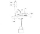
- FIG. 12 is a diagram for explaining the basic principle of a conventional observation and photographing apparatus. As shown in FIG. 12, the surface of the sample 101 is observed with the microscope 102. In addition, the imaging unit 103 attached to the microscope 102 captures the surface of the sample 101 and records it in the form of an image.
- the surface of the sample 101 is mirror-finished by a polishing mechanism before observation or photographing.
- Various polishing mechanisms for polishing the sample 101 have been proposed (see, for example, Patent Document 2).
- FIG. 13 is a diagram for explaining the basic principle of a conventional polishing mechanism.
- the sample 101 is placed on the rotary table 105.
- a polishing liquid 106 containing fine abrasive particles is supplied to the sample 101 from a downward nozzle 108.
- the polishing liquid 106 containing abrasive particles flows on the upper surface of the sample 101 by centrifugal force.
- the upper surface of the sample 101 is polished by applying a rotating polishing cloth 107 to the upper surface of the sample 101. Thereafter, the image is observed with the microscope 102 indicated by an imaginary line and photographed by the imaging unit 103.
- some of the fine abrasive particles remain on the polishing cloth 107 in a form of being bitten into the polishing cloth 107.
- the abrasive particles are crushed with use. Since the fracture surface is sharp, the sample 101 is scratched if left alone. The crushed abrasive particles also stay on the upper surface of the sample 101. A part of the cut sample damages the sample 101. As a result, the upper surface of the sample 101 is rough, and the quality of the sample 101 is deteriorated.
- the quality can be prevented from being deteriorated by exchanging or cleaning the polishing cloth 107.
- exchanging since it is necessary to stop the polishing mechanism, the operating rate of the observation and photographing apparatus is lowered.
- the crushed abrasive particles are biting into the polishing cloth 107.
- the abrasive particles are scraped off the polishing cloth 107 using a spatula or squeegee.
- the polishing cloth 107 hurts with a spatula or squeegee.
- Polishing has been conventionally performed by electrolytic treatment.
- the surface of the sample can be smoothed by electropolishing.
- an electrolytic polishing plate and an electrolytic polishing cloth or an electrolytic bath are generally required.
- the electropolishing plate and the electropolishing cloth or the electrolyzer are provided separately, which increases the polishing mechanism. Miniaturization of the polishing mechanism is required.
- the surface of the sample becomes dirty with the solute component of the sample. It is possible to prevent contamination by changing the electrolyte solution every time. However, a large amount of electrolyte is required. It is desirable to reduce the required amount of electrolyte.
- the polishing amount is 100 nm to several tens of ⁇ m, which is very small.
- the measuring device for measuring the polishing amount is supported on the machine base via the support, but if the support is deformed, an error occurs in the measured value of the polishing amount. Further, if the sample stage (such as a rotary table) on which the sample is placed is deformed, an error occurs in the measured value of the polishing amount. In the conventional structure, it is difficult to increase the measurement accuracy of the polishing amount. Therefore, a structure capable of increasing the measurement accuracy of the polishing amount is required.
- the surface of the sample may be corroded with chemicals. This technique is called a chemical etching method. If the corrosive liquid is scattered and contacts the microscope or the polishing amount measuring device, the microscope or the polishing amount measuring device may be damaged. Countermeasures are required.
- the microscope 102 is adjusted so that the upper surface of the sample 101 is in focus. Since adjustment of the microscope 102 is cumbersome, focus adjustment is performed before observation. However, when the sample 101 is repeatedly polished with the polishing cloth 107, the surface is lowered. When the surface is lowered, the image becomes out of focus and the image becomes blurred. It is desired that a clear image can be obtained even when the surface is lowered.
- imaging is performed while moving the microscope 102 along the surface 101 of the sample, polishing is performed, and imaging while moving the microscope 102 along the surface of the sample 101 is repeated.
- the acquired images can be stacked to form a stereoscopic image. Due to mechanical errors typified by backlash, the microscope 102 may not return to its original position accurately. Then, the image becomes unclear. Even when the microscope 102 moves, it is desirable to obtain a clear image.
- the present invention provides an observation imaging apparatus equipped with a physical and chemical polishing mechanism, which can reduce the amount of cleaning liquid required, and further achieves good polishing amount measurement accuracy and good observation while reducing the overall size of the apparatus. It is another object of the present invention to provide an observation and photographing apparatus that can obtain an image, has good maintenance performance and durability, and has a clear image even when the microscope moves.
- the invention according to claim 1 is a polishing mechanism in which a microscope with an imaging unit capable of observing and photographing the surface of a sample is repeatedly ground at an equal interval or set amount in the vertical direction prior to the observation.
- the polishing mechanism includes a rotating disk having a vertical rotation axis, a polishing cloth attached to the lower surface of the rotating disk, and polishing the surface of the sample, and the polishing cloth.
- a polishing liquid injection nozzle is provided, which is disposed below and in which a polishing liquid containing an abrasive is sprayed upward to wet the polishing cloth.
- the polishing cloth includes an inner polishing cloth disposed at the center of the lower surface of the rotating disk, and at least one outer polishing cloth disposed on the lower surface of the rotating disk so as to surround the inner polishing cloth. It is characterized by comprising.
- the invention according to claim 3 is characterized in that the inner polishing cloth is finer than the outer polishing cloth.
- a microscope equipped with an imaging unit capable of observing and photographing the surface of a sample, and electrolytically polishing the surface of the sample repeatedly at equal intervals or in the vertical direction prior to the observation.
- An observation and photographing device with a polishing mechanism The electrolytic polishing mechanism includes a rotating disk having a vertical rotation axis, an electrolyte absorbing cloth that is attached to the lower surface of the rotating disk and absorbs an electrolytic solution that electrolytically polishes the observation surface, and is disposed below the electrolytic absorbing cloth. And an electrolyte injection nozzle for injecting the electrolyte upward to wet the electrolyte absorbing cloth.
- the invention according to claim 5 is characterized in that the corrosive liquid is jetted from the electrolyte jet nozzle.
- a measuring instrument that measures the distance to the surface or observation surface of the sample, and an arithmetic unit that calculates the polishing amount from the difference between the distance before polishing and the distance after polishing measured by this measuring instrument It is characterized by having.
- a measuring instrument that measures the distance to the surface or the observation surface of the sample, and a plurality of points on the surface or the observation surface are measured by this measuring instrument, and the obtained measurement values are statistically measured.
- a statistical processing unit for obtaining the surface roughness by processing.
- the rotating disk is disposed in the cylindrical cover
- the microscope with the imaging unit is disposed outside the cylindrical cover
- the spray region of the polishing liquid spray nozzle or the electrolytic solution spray nozzle is in the cylindrical cover. It is characterized by being set to.
- the sample table lifting mechanism for moving the polished or electrolytically polished sample to the observation position of the microscope with an imaging unit, and the surface or the observation surface so as to coincide with the focus of the microscope with the imaging unit. It is characterized by comprising a control unit for controlling the sample table elevating mechanism in anticipation of the polishing amount.
- the microscope with an imaging part is attached to the stage which moves horizontally, a control part preserve
- the polishing liquid spray nozzle is disposed under the polishing cloth, and the polishing liquid is sprayed upward from the polishing liquid spray nozzle.
- the polishing liquid hits the lower surface of the polishing cloth, wets the polishing cloth, and is subjected to wet polishing.
- the polishing liquid falls from the polishing cloth by its own weight.
- the abrasive (particles) that has been subjected to polishing and crushed falls together with the polishing liquid. That is, the deteriorated polishing liquid quickly leaves the polishing cloth.
- an observation imaging apparatus that can reduce the required amount of the cleaning liquid in the observation imaging apparatus provided with the polishing mechanism.
- an inner side polishing cloth and an outer side polishing cloth are arrange
- rough polishing and final polishing can be performed.
- rough polishing and finish polishing can be performed by changing the particle size of the abrasive contained in the supplied polishing liquid.
- rough polishing and final polishing can be performed with one rotating disk on which the inner polishing cloth and the outer polishing cloth are arranged.
- the inner polishing cloth is finer than the outer polishing cloth. Rough polishing is performed with the outer polishing cloth, and final polishing is performed with the inner polishing cloth close to the rotation center. In rough polishing, an abrasive having a relatively large particle size is used. It is not preferable that the abrasive having a large particle size adheres to the inner polishing cloth.
- a polishing liquid containing an abrasive having a large particle size is sprayed on the outer polishing cloth, the polishing liquid is moved outward by the centrifugal force, and as a result, there is no fear of entering the inner polishing cloth.
- a polishing liquid containing an abrasive having a small particle diameter is sprayed onto the inner polishing cloth. This polishing liquid is moved outward by the centrifugal force and enters the outer polishing cloth, but does not affect the rough polishing because the particle size of the abrasive is small.
- an electrolyte solution cloth and an electrode are provided in a rotating plate.
- the observation and photographing apparatus can be made more compact than a separate electropolishing plate or electropolishing tank.
- Excess electrolyte falls from the electrolyte absorbent cloth due to its own weight.
- the dirty electrolytic solution falls together with the electrolytic solution. That is, the deteriorated electrolytic solution quickly leaves the electrolytic solution absorbing cloth. Since the deteriorated electrolyte does not stay on the electrolyte absorbing cloth surface, there is no fear of unnecessary dirt on the electrolytic treatment surface, and the quality of the sample is kept good. Since the deteriorated electrolytic solution does not stay on the processing surface, it is not necessary to clean with a large amount of cleaning solution, and the required amount of the electrolytic solution can be reduced.
- the observation and photographing apparatus can be made compact.
- the corrosive liquid is jetted from the electrolyte jet nozzle.
- the sample can be etched, and the application of the observation and photographing apparatus is expanded.
- polishing are provided.
- the amount of polishing is accurately and easily determined.
- a distance provided with a statistical processing unit for measuring a plurality of locations on the surface or observation surface with a measuring instrument and statistically processing the obtained plurality of measured values to obtain surface roughness.
- a measuring instrument for measuring, and a calculation unit for calculating the polishing amount from the difference between the distance before polishing and the distance after polishing are provided. In parallel with the observation of the sample, the surface roughness can be obtained, and the application of the observation imaging apparatus is expanded.
- the rotating disk is disposed in the cylindrical cover
- the microscope with the imaging unit is disposed outside the cylindrical cover
- the spray region of the polishing liquid spray nozzle or the electrolytic solution spray nozzle is in the cylindrical cover.
- the invention according to claim 9 is provided with a control unit that controls the sample table elevating mechanism in anticipation of the polishing amount so that the surface or the observation surface matches the focal point of the microscope with the imaging unit. Due to the action of the control unit, it is possible to always obtain good imaging.
- the control unit stores the image before moving by the stage, and controls the stage so that the microscope with the imaging unit moved by the stage returns to the original position based on the image before moving. It also has a control function.
- the stage inevitably contains mechanical errors such as backlash. If left unattended, the image becomes unclear. According to the present invention, even if there is a mechanical error such as backlash, the control unit accurately returns the microscope to the original position.
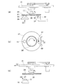
- FIG. 2 is a sectional view taken along line 2-2 of FIG.
- FIG. 3 is a sectional view taken along line 3-3 in FIG. 1. It is sectional drawing of a turntable.
- FIG. 5 is a view taken in the direction of arrow 5 in FIG. It is a systematic diagram of polishing liquid and cleaning liquid. It is an effect
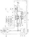
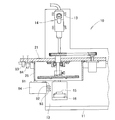
- the observation and imaging apparatus 10 includes a base plate 11 that extends horizontally, a wall plate 12 that stands from the base plate 11, and a microscope 14 that is fixed to the upper portion of the wall plate 12 and includes an imaging unit 13. And a sample stage 16 which is provided on the wall plate 12 so as to be movable up and down at a position below the microscope 14 and supports the sample 15, and a polishing mechanism 20 which is provided on the wall plate 12 so as to be horizontally movable.
- the polishing mechanism 20 is lowered from the slider 21, a slider 21 that moves horizontally, a rotary shaft 23 that is vertically attached to the slider 21 via a bearing 22, a rotary disc 24 that is attached to the lower end of the rotary shaft 23, and the slider 21.
- a first polishing liquid spray nozzle 31 that sprays the polishing liquid onto the outer polishing cloth 27 and a first polishing liquid that is fixed to the lower end of the cylindrical cover 25 and disposed below the outer polishing cloth 27 and sprays the cleaning liquid upward onto the outer polishing cloth 27.
- the rotating disk drive motor 37 rotates the rotating disk 24 in a predetermined direction at a predetermined speed.
- the belt 41 is preferably a timing belt (toothed belt), but may be a chain. In the case of a chain, the pulleys 38 and 39 are changed to sprockets.
- non-contact type laser measuring devices 83 and 84 are mounted side by side on one end of the slider 21 closer to the sample stage 16. These laser measuring devices 83 and 84 are arranged above the nozzles 31 to 34. Further, the laser measuring instruments 83 and 84 are disposed outside the cylindrical cover 25.
- the microscope 14 is attached to the wall plate 12 via a manual or electric XY stage 17 that moves in the horizontal direction.
- the observer 42 can visually observe the upper surface of the sample 15 indicated by an imaginary line by bringing the eye 44 close to the eyepiece 43. Further, the upper surface of the sample 15 can be photographed by the imaging unit 13 provided in the microscope 14.
- the microscope 14 can move horizontally by about 1 cm by the action of the stage 17.
- the observer 42 can observe without changing the posture. Since the microscope 14 is attached to the wall plate 12, the height from the floor does not change.
- the observer 42 can observe with a fixed posture.
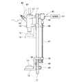
- the sample stage elevating mechanism 45 is, for example, an elevating motor 46 fixed to the upper back of the wall plate 12, an elevating feed screw 47 extending downward from the elevating motor 46, and an elevating and lowering mechanism provided on the sample stage 16.
- the nut 48 meshes with the feed screw 47.
- the elevating feed screw 47 is preferably a precise ball screw.
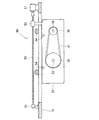
- the slider moving mechanism 50 includes, for example, a stepping motor 51 fixed to the back surface of the wall plate 12, a horizontal movement feed screw 52 extending horizontally from the stepping motor 51, and the slider 21. It comprises a nut 53 that is provided and meshes with a feed screw 52 for horizontal movement. When the feed screw 52 for horizontal movement is rotated by the stepping motor 51, the nut 53 moves and the slider 21 moves horizontally.
- the stepping motor 51 is called a control motor and can control the rotation speed and rotation angle (rotation amount).
- the control motor is preferably a stepping motor, but may be a servo motor.
- the slider 21 It is desirable to provide the slider 21 with a plurality of rollers 54 that sandwich the wall plate 12. By sandwiching the wall plate 12 with the plurality of rollers 54, the slider 21 can be moved without shaking.
- the horizontal movement feed screw 52 is preferably a precise ball screw.
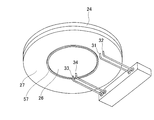
- a ring-shaped partition wall 57 is integrally formed on the lower surface of the turntable 24.
- a disc-shaped inner polishing cloth 26 is attached to the inner side of the partition wall 57 and the lower surface of the rotating disk 24.
- a doughnut-shaped outer polishing cloth 27 is attached to the outside of the partition wall 57 and on the lower surface of the turntable 24.
- the inner polishing cloth 26 is a polishing cloth for finish polishing (mirror finish)
- the outer polishing cloth 27 is a polishing cloth for rough polishing.
- the inner polishing cloth 26 has finer eyes than the outer polishing cloth 27.
- the first polishing liquid spray nozzle 31 and the first cleaning liquid spray nozzle 32 are disposed under the outer polishing cloth 27, and the second polishing liquid spray nozzle 33 and the second cleaning liquid spray nozzle 32 are disposed under the inner polishing cloth 26.
- a cleaning liquid injection nozzle 34 is disposed. The tips of the nozzles 31 and 32 are directed to the outer polishing cloth 27, and the tips of the nozzles 33 and 34 are directed to the inner polishing cloth 26.
- the automatic valve 59 and the cleaning liquid supply source 61 are connected to the first cleaning liquid injection nozzle 32 via the tube 58.
- the automatic valve 59 is opened, the first cleaning liquid 62 is injected from the first cleaning liquid injection nozzle 32, and when the automatic valve 59 is closed, the injection stops.
- a first polishing liquid container 64 is connected to the first polishing liquid injection nozzle 31 through a tube 63.
- a magnetic stirring bar 65 is accommodated in the first polishing liquid container 64.
- an automatic valve 66 and a driving gas source 67 are connected to the first polishing liquid container 64.
- the first polishing liquid container 64 is filled with a first polishing liquid 68 containing a particulate abrasive. By stirring with the magnetic stirrer 65, settling of the abrasive is prevented and dispersion is achieved.
- the automatic valve 66 is opened, the first polishing liquid 68 is compressed with high-pressure gas, and as a result, the first polishing liquid 68 is jetted from the first polishing liquid jet nozzle 31.
- the automatic valve 66 is closed, the injection stops.
- an automatic valve 72 and a cleaning liquid supply source 73 are connected to the second cleaning liquid injection nozzle 34 via a tube 71.
- the automatic valve 72 is opened, the second cleaning liquid 74 is injected from the second cleaning liquid injection nozzle 34, and when the automatic valve 72 is closed, the injection is stopped.
- a second polishing liquid container 76 is connected to the second polishing liquid injection nozzle 33 via a tube 75.
- a magnetic stirrer 77 is accommodated in the second polishing liquid container 76.
- an automatic valve 78 and a driving gas source 79 are connected to the second polishing liquid container 76.
- the second polishing liquid container 76 is filled with a second polishing liquid 81 containing fine abrasive particles finer than the fine particles contained in the first polishing liquid 68.
- the automatic valve 78 When the automatic valve 78 is opened, the second polishing liquid 81 is compressed with high-pressure gas, and as a result, the second polishing liquid 81 is jetted from the second polishing liquid jet nozzle 33.
- the automatic valve 78 When the automatic valve 78 is closed, the injection stops.
- the first polishing liquid 68 is a polishing liquid for rough polishing, and includes a relatively large diameter abrasive.
- the second polishing liquid 81 is a polishing liquid for finish polishing, and includes a relatively small diameter abrasive.
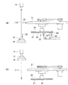
- the turntable 24 is rotated at a predetermined rotation speed (arrow (1)).
- a first polishing liquid 68 containing an abrasive having a relatively large particle size is sprayed upward from the first polishing liquid spray nozzle 31 to the outer polishing cloth 27.
- the sample stage 16 by raising the sample stage 16 as indicated by the arrow (2), the upper surface of the sample 15 is brought into contact with the outer polishing cloth 27 with a predetermined load. This contact is continued for a predetermined time.
- the first polishing liquid 68 is sprayed upward and wets the lower surface of the outer polishing cloth 27.
- the first polishing liquid 68 falls from the outer polishing cloth 27 by its own weight.
- the abrasive (particles) that has been subjected to polishing and crushed falls together with the first polishing liquid 68. That is, the deteriorated polishing liquid leaves the polishing cloth. Since the deteriorated polishing liquid does not stay on the polishing surface, there is no fear of unnecessary scratches on the polishing surface, and the quality of the sample is kept good.
- the first polishing liquid 68 hits a part of the outer polishing cloth 27. Since the outer polishing cloth 27 is rotating, the entire surface of the outer polishing cloth 27 is wetted with the first polishing liquid 68. The wet outer polishing cloth 27 contacts the sample 15, and the sample 15 is roughly polished. At this time, since centrifugal force is applied to the first polishing liquid 68, the first polishing liquid 68 moves outward as indicated by an arrow (3). Therefore, there is no fear that the first polishing liquid 68 enters the inner polishing cloth 26.
- the sample 15 is lowered (arrow (4)) as shown in FIG.
- the slider 21 is moved as shown by the arrow (5).
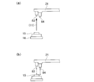
- FIG. 8A when the position of the sample 15 is moved to an appropriate position of the inner polishing cloth 26, the movement is stopped.
- a second polishing liquid 81 containing an abrasive having a relatively small particle size is sprayed upward from the second polishing liquid spray nozzle 33 onto the inner polishing cloth 26 to the inner polishing cloth 26.
- the upper surface of the sample 15 is brought into contact with the inner polishing cloth 26 by raising the sample stage 16 as indicated by an arrow (6).
- FIG. 8B the upper surface of the sample 15 is finish-polished with the inner polishing cloth 26 for a predetermined time at a predetermined rotational speed and a predetermined load.
- the second polishing liquid 81 hits a part of the inner polishing cloth 26. Since the inner polishing cloth 26 is rotating, the entire surface of the inner polishing cloth 26 is wetted. The wet inner polishing cloth 26 comes into contact with the sample 15, and the sample 15 is finished and polished. At this time, since the centrifugal force is applied to the second polishing liquid 81, the second polishing liquid 81 moves outward as indicated by an arrow (7). However, since the abrasive particle size is small, it does not affect the rough polishing.
- the sample 15 is lowered (arrow (8)), and then the slider 21 is returned to the standby position (arrow (9)). Thereafter, the first cleaning liquid 62 is sprayed from the first cleaning liquid spray nozzle 32 onto the lower surface of the outer polishing cloth 27 to clean the outer polishing cloth 27. At the same time, the second cleaning liquid 74 is sprayed from the second cleaning liquid spray nozzle 34 onto the lower surface of the inner polishing cloth 26 to clean the inner polishing cloth 26.
- the sample 15 is raised as shown by the arrow (10). As shown in (b), the upper surface of the sample 15 is observed and / or photographed with the microscope 14. When finished, the sample 15 is lowered to the standby position as shown by the arrow (11).
- the first polishing liquid 68 falls from the outer polishing cloth 27 by its own weight.
- the abrasive (particles) that has been subjected to polishing and crushed falls together with the first polishing liquid 68. That is, the deteriorated first polishing liquid 68 is separated from the outer polishing cloth 27.
- the deteriorated first polishing liquid 68 does not stay on the polished surface, there is no fear of unnecessary scratches on the polished surface, and the quality of the sample is kept good. Since the deteriorated first polishing liquid 62 does not stay on the polishing surface, it is not necessary to clean with a large amount of the first cleaning liquid 62, and the required amount of the first cleaning liquid 62 can be reduced. As described with reference to FIGS. 8A and 8B, the same applies to the second polishing liquid 81.
- a single disk-shaped polishing cloth may be attached to the rotating disk 24.
- three types of polishing such as rough polishing, intermediate polishing, and final polishing, in FIG. 4, one inner polishing cloth is reduced in diameter, and two inner polishing cloths 26 having a smaller diameter (2 Enclose with outer polishing cloth of ring). That is, three types of polishing cloths may be provided on the rotating disk 24 in a concentric circle shape.
- FIG. 1 shows an example of the configuration of the polishing mechanism 20
- FIG. 2 shows an example of the configuration of the sample stage moving mechanism 45
- FIG. 3 shows an example of the configuration of the slider moving mechanism 50.
- the layout can be changed as appropriate.
- the inner polishing cloth is made finer than the outer polishing cloth, but the outer polishing cloth and the inner polishing cloth are made the same roughness, and the particle size of the abrasive contained in the polishing liquid can be changed.
- rough polishing and finish polishing can be performed. That is, the roughness of the outer polishing cloth and the inner polishing cloth are changed or the same, and the abrasive contained in the polishing liquid sprayed from the first polishing liquid spray nozzle and the polishing liquid sprayed from the second polishing liquid spray nozzle Rough polishing and final polishing can be performed by appropriately selecting four combinations of changing or making the particle size of the abrasive contained therein the same.
- the inner polishing cloth is replaced with another cloth and the inner polishing liquid is replaced with another liquid.
- the inner polishing cloth as the inner electrolyte absorbing cloth and the inner polishing liquid as the electrolytic solution
- electrolytic polishing or electrolytic corrosion, or treatment using electrolytic corrosion and electrolytic polishing in combination can be performed.
- the polishing cloth as the electrolyte absorbing cloth and the polishing liquid spray nozzle as the electrolyte spray nozzle, the electrolyte is sprayed upward from the electrolyte spray nozzle.
- the slider 21 is stopped.
- the turntable 24 is rotated to inject the electrolyte solution 81 upward from the second electrolyte solution injection nozzle 33 onto the inner electrolyte solution cloth 26 onto the inner electrolyte solution cloth 26.
- the upper surface of the sample 15 is brought into contact with the inner electrolyte absorbing cloth 26 by raising the sample stage 16 as indicated by the arrow (6).
- a current is passed through the inner electrolyte solution cloth 26 and the sample 15.
- an insulating structure is appropriately employed so that the inner electrolyte solution absorbent cloth 26 and the sample 15 are not electrically short-circuited.
- the electrode may use a rotating plate 24.
- the electrode is attached to the portion in contact with the inner electrolyte absorbent cloth 26. In the latter case, it is only necessary to replace the electrode. That is, when the electrode is corroded, only the electrode needs to be replaced, which is advantageous in terms of cost.
- the upper surface of the sample 15 is electrolytically polished or electrolytically corroded with the inner electrolyte absorbent cloth 26 for a predetermined time at a predetermined rotational speed and a predetermined polishing load.
- the second electrolyte solution 81 hits a part of the inner electrolyte absorbent cloth 26.
- the entire surface of the inner electrolyte absorbent cloth 26 is rotated. Gets wet.
- the inner electrolyte absorbing cloth 26 comes into contact with the sample 15, and the sample 15 is subjected to electrolytic polishing or electrolytic corrosion.
- the second electrolyte solution 81 moves outward as indicated by an arrow (7).
- the second electrolytic solution 81 does not contain large particles, the rough polishing is not affected.
- the sample 15 is lowered (arrow (8)), and then the slider 21 is returned to the standby position (arrow (9)), as shown in FIG. 9 (a). Thereafter, the second cleaning liquid 74 is sprayed from the second cleaning liquid spray nozzle 34 onto the lower surface of the inner electrolyte absorbing cloth 26 to clean the inner electrolyte absorbing cloth 26.
- the deteriorated electrolyte does not stay on the polished surface, there is no fear of unnecessary contamination on the sample observation surface, and the sample quality is kept good. Since a large amount of the deteriorated electrolyte does not stay on the inner electrolyte absorbent cloth 26, it is not necessary to clean the inner electrolyte absorbent cloth 26 with a large amount of the second cleaning liquid 74, and the required amount of the second cleaning liquid 74 may be reduced. it can.
- the polishing amount is measured.
- measurement is performed before the electrolytic treatment every time. In the measurement, it is desired that the sample surface is smooth.
- the other laser measuring instrument 84 measures a portion that is not polished.
- the distance information obtained by the laser measuring device 83 and the laser measuring device 84 are input to the calculation unit (FIG. 1, reference numeral 85).
- the calculation unit obtains the difference between the two distances and sets it as the polishing amount.
- the laser measuring instruments 83 and 84 When it is desired to perform measurement at a large number of positions, the laser measuring instruments 83 and 84 are moved horizontally. A large number of distance information obtained by the laser measuring devices 83 and 84 is sent to the statistical processing unit (reference numeral 86 in FIG. 1). The statistical processing unit statistically processes a large number of distance information to obtain the surface roughness. By this statistical processing, the distance is accurately measured even if the surface has irregularities.
- the slider 21 is then returned to the standby position as shown in FIG. 9A (arrow (9)).
- the observation of the sample is a tissue observation
- nitrate alcohol having a concentration of several percent of nitric acid and other corrosive liquids are often used. A preferred configuration example in this case will now be described.
- a nozzle unit 94 comprising a corrosive nozzle 91 for injecting corrosive liquid, a cleaning nozzle 92 for injecting cleaning liquid, and a drying nozzle 93 for injecting dry air is prepared.
- the cylindrical cover 25 and the slider 21 are interposed between the nozzle unit 94, the microscope 14, and the measuring instruments 83 and 84. That is, the nozzle unit 94 is disposed under or in the cylindrical cover 25.
- the nozzle unit 94 may be attached to the wall plate 12, but is preferably attached to the cylindrical cover 25.
- Water or hot water is sprayed from the cleaning nozzle 92. It is recommended that the sample 15 be swung up and down during this injection. This is because the cleaning effect is enhanced.
- the sample be cleaned with the cleaning nozzle 92 after a few seconds to a few minutes have passed after the etching solution is applied to the sample.
- the chemical etching can be stopped by cleaning.
- the amount of corrosion can be controlled with high accuracy. By this direct cleaning, the polishing liquid remaining on the sample can be removed.
- Dry air, inert gas, and hot gas are sprayed from the drying nozzle 93.
- the surface of the sample 15 can be dried and the remaining cleaning liquid and dirt can be removed. It is recommended that the sample 15 be swung up and down during the gas blow. This is because drying time is shortened and drying unevenness is eliminated.
- the sample 15 is raised (arrow (10)) and moved to the observation position of the microscope 14, and the amount of polishing is expected for this movement. That is, the upper surface of the sample 15 is lowered by the polishing amount. Therefore, the sample stage 16 is raised by a movement amount obtained by adding the value of the polishing amount measurement or the predicted setting of the polishing amount. As a result, the surface of the sample 15 is always at the focus of the microscope 14. If necessary, adjust the focus for image recognition. This control is collectively performed by the control unit (FIG. 1, reference numeral 87). As described above, there has been a conventional image blur, but according to the present invention, a clear image is always obtained.
- the eyepiece unit 43 can be omitted.
- the microscope 14 according to the present invention is arbitrarily selected from two forms, one having the eyepiece 43 and one having no eyepiece 43.
- the microscope 14 is attached to the wall plate 12 via a manual or electric XY stage 17 that moves in the horizontal direction.
- a position control motor such as a stepping motor or a servo motor attached to the electric stage is used.
- the microscope can be moved, and adjacent fields of view on the same polished surface can be continuously photographed. Save the first image on the control PC before moving it.
- the stage is moved by controlling the amount of motor movement, and necessary images are taken and stored so that adjacent images have overlapping portions.
- the microscope XY stage is returned to the field of view prior to the movement by controlling the motor movement amount.
- the visual field shift occurs due to machine accuracy or the like, but the first image, that is, the image before being moved is precisely aligned with the image recognition.
- This control is also performed by the control unit (FIG. 1, reference numeral 87).
- the adjacent images of the same observation surface obtained by this operation can be easily corrected by the user using a commercially available image software different from this apparatus, and the image is made into one image. be able to.
- the present invention is suitable for an observation imaging apparatus for observing and imaging a sample surface while repeatedly polishing the surface of the sample at equal intervals or a set amount.
Landscapes
- Engineering & Computer Science (AREA)
- Mechanical Engineering (AREA)
- Chemical & Material Sciences (AREA)
- Chemical Kinetics & Catalysis (AREA)
- Electrochemistry (AREA)
- Physics & Mathematics (AREA)
- Materials Engineering (AREA)
- Metallurgy (AREA)
- Organic Chemistry (AREA)
- Analytical Chemistry (AREA)
- General Physics & Mathematics (AREA)
- Optics & Photonics (AREA)
- Multimedia (AREA)
- Biochemistry (AREA)
- Health & Medical Sciences (AREA)
- Life Sciences & Earth Sciences (AREA)
- Computer Vision & Pattern Recognition (AREA)
- General Health & Medical Sciences (AREA)
- Immunology (AREA)
- Pathology (AREA)
- Sampling And Sample Adjustment (AREA)
- Constituent Portions Of Griding Lathes, Driving, Sensing And Control (AREA)
- Finish Polishing, Edge Sharpening, And Grinding By Specific Grinding Devices (AREA)
Abstract
Description
撮像部付き顕微鏡は、試料の表面を観察し撮影する。
研磨機構は、試料の表面を等間隔又は設定した量を繰返し物理的、化学的に研磨する。
試料には、必要であれば観察に有利となるエッチング処理が施される。
観察装置によって得られた画像は、3次元構築を行い試料の3次元観察や数値化に利用される。
観察撮像装置は、シリアルセクショニング法と呼ばれる、観察を自動的に行う装置に相当する。
図12は従来の観察撮影装置の基本原理を説明する図である。図12に示されるように、試料101の表面が、顕微鏡102で観察される。また、この顕微鏡102に付属する撮像部103で、試料101の表面が撮影され、画像の形態で記録される。
試料101を研磨する研磨機構が各種提案されている(例えば、特許文献2参照。)。
図13は従来の研磨機構の基本原理を説明する図である。図13に示されるように、回転テーブル105に試料101が載せられる。この試料101に微細な研磨粒子を含む研磨液106が下向きノズル108から供給される。研磨粒子を含む研磨液106は遠心力により試料101の上面を流れる。試料101の上面に、回転する研磨布107を当てることで、試料101の上面が研磨される。その後に、想像線で示される顕微鏡102で観察し、撮像部103で撮影がなされる。
また、破砕された研磨粒子が研磨布107に食い込んでいる。洗浄する場合は、へらやスキージを用いて研磨粒子を研磨布107からそぎ落とす。へらやスキージで研磨布107が痛む。その上で、多量の洗浄液で時間を掛けて研磨粒子を洗い流す必要がある。
洗浄する場合は、研磨布107の寿命が短くなると共に洗浄液の所要量が多量となる。
従来の構造では、研磨量の測定精度を高まることが難しい。よって、研磨量の測定精度を高めることができる構造が求められる。
腐食性液体が、飛散して顕微鏡や研磨量測定器に接触すると、顕微鏡や研磨量測定器にダメージを与える虞がある。その対策が求められる。
しかし、研磨布107で試料101が、繰り返し研磨されると、表面が下がってくる。表面が下がってくると、焦点が合わなくなり、画像がぼやける。表面が下がっても鮮明な画像が得られることが望まれる。
バックラッシュに代表される機械的誤差により、顕微鏡102が元の位置に正確に戻らないことがある。すると、画像が不鮮明になる。
顕微鏡102が移動する場合であっても、鮮明な画像が得られることが望まれる。
前記電解研磨機構は、回転軸が鉛直である回転盤と、この回転盤の下面に取付けられ観察面を電解研磨する電解液を吸収する電解液吸収布と、この電解液吸収布より下に配置され上向きに前記電解液を噴射して前記電解液吸収布を濡らす電解液噴射ノズルとを備えていることを特徴とする。
研磨液は研磨布の下面に当たり、研磨布を濡らし、湿式研磨に供される。
研磨液は、自重により研磨布から落下する。研磨に供され破砕した研磨材(粒子)は、研磨液と共に落下する。すなわち、劣化した研磨液は研磨布から速やかに離れる。
よって、本発明によれば、研磨機構を備える観察撮影装置において、洗浄液の所要量を少なくすることができる観察撮影装置が提供される。
内側研磨布と外側研磨布の粗さを変えることで、粗研磨と仕上げ研磨とが実施できる。また、内側研磨布と外側研磨布が同一粗さであっても、供給する研磨液に含まれる研磨材の粒径を変えることで、粗研磨と仕上げ研磨とが実施できる。結果、内側研磨布と外側研磨布が配置される1個の回転盤で、粗研磨と仕上げ研磨を実施することができる。
粗研磨用回転盤と仕上げ研磨用回転盤を各々備えるよりは、本発明によれば、観察撮影装置のコンパクト化が図れる。
外側研磨布で粗研磨を実施し、回転中心に近い内側研磨布で仕上げ研磨を実施する。
粗研磨では比較的粒径の大きな研磨材を用いる。この粒径の大きな研磨材が内側研磨布に付着することは好ましくない。外側研磨布に粒径の大きな研磨材を含む研磨液を噴射すると、この研磨液は遠心力により径外方へ動かされ、結果、内側研磨布に侵入する心配はない。
粒径の小さな研磨材を含む研磨液を内側研磨布へ噴射する。この研磨液は遠心力により径外方へ動かされ、外側研磨布へ侵入するが、研磨材の粒径が小さいため、粗研磨には影響しない。
余分な電解液は、自重により電解液吸収布から落下する。電解処理を行いながら電解液を供給することで、汚れた電解液は、電解液と共に落下する。すなわち、劣化した電解液は電解液吸収布から速やかに離れる。
劣化した電解液が電解液吸収布面に留まらないため、電解処理面に無用な汚れが付く心配が無く、試料の品質が良好に保たれる。劣化した電解液が処理面に留まらないため、多量の洗浄液によって洗浄する必要がなく、電解液の所要量を少なくすることができる。
研磨量が正確に且つ簡単に求められる。
試料の観察に並行して、表面あらさを求めることができ、観察撮影装置の用途が拡大する。
観察者42は、接眼部43に目44を近づけることにより、想像線で示される試料15の上表面を目視することができる。また、顕微鏡14に備える撮像部13で、試料15の上表面を撮影することができる。
顕微鏡14は壁板12に取付けられているため、床からの高さは変わらない。観察者42は決まった姿勢で観察を行うことができる。
昇降用送りねじ47は、精密なボールねじが好適である。
ステッピングモータ51により水平移動用送りねじ52を回すと、ナット53が移動し、スライダ21が水平に移動する。ステッピングモータ51は制御モータと呼ばれ、回転速度や回転角(回転量)を制御することができる。
なお、制御モータはステッピングモータが好適であるがサーボモータであってもよい。
水平移動用送りねじ52は、精密なボールねじが好適である。
また、壁板12に水平移動用送りねじ52の先端を回転自在に支承するねじ受け台55を設けることが望まれる。水平移動用送りねじ52が長いが、ねじ受け台55により先端の振れを防止することができる。
内側研磨布26は仕上げ研磨(鏡面仕上げ)用研磨布であり、外側研磨布27は粗研磨用研磨布である。外側研磨布27よりも、内側研磨布26の目は細かい。
第1研磨液容器64に、微粒子状の研磨材を含む第1研磨液68が充填される。磁気撹拌子65で撹拌することで、研磨材の沈降を防止し、分散化を図る。
自動弁66が開かれると、高圧気体で第1研磨液68が圧縮され、結果、第1研磨液68が第1研磨液噴射ノズル31から噴射される。自動弁66を閉じると噴射が停止する。
第2研磨液容器76に、第1研磨液68に含まれる微粒子より細かい微粒子状の研磨材を含む第2研磨液81が充填される。磁気撹拌子77で撹拌することにより、研磨材が沈降する心配は無く、研磨材は分散する。
自動弁78が開けられると、高圧気体で第2研磨液81が圧縮され、結果、第2研磨液81が第2研磨液噴射ノズル33から噴射される。自動弁78を閉じると噴射が停止する。
図7(a)において、所定回転速度で回転盤24が回される(矢印(1))。第1研磨液噴射ノズル31から外側研磨布27へ、比較的粒径の大きな研磨材を含む第1研磨液68が、上向きに噴射される。そして、試料台16を矢印(2)のように上昇させることで、所定荷重にて試料15の上面を外側研磨布27に接触させる。この接触は所定時間継続される。
劣化した研磨液が研磨面に留まらないため、研磨面に無用な傷が付く心配が無く、試料の品質が良好に保たれる。
濡れている外側研磨布27が試料15に接触し、試料15を粗研磨する。この際、第1研磨液68に遠心力が加わるため、外方へ矢印(3)のように移動する。そのために、第1研磨液68が内側研磨布26へ侵入する心配はない。
図8(b)に示されるように、所定回転速度、更に所定荷重にて、所定時間だけ、内側研磨布26で試料15の上面を仕上げ研磨する。
(c)に示されるように、内側研磨布26の一部分に第2研磨液81が当たる。内側研磨布26が回転しているため、内側研磨布26の全面が濡らされる。濡れている内側研磨布26が試料15に接触し、試料15を仕上げ研磨する。この際、第2研磨液81に遠心力が加わるため、径外方へ矢印(7)のように移動する。しかし、研磨材の粒径が小さいため、粗研磨には影響しない。
並行して、試料15を矢印(10)のように上昇させる。
(b)に示されるように、試料15の上面を顕微鏡14で観察及び又は撮影する。終わったら、矢印(11)のように、試料15を待機位置まで下げる。
図8(a)、(b)で説明したように、第2研磨液81についても同様である。
また、粗研磨、中研磨、仕上げ研磨のように3種の研磨を必要とする場合は、図4において、1個の内側研磨布を小径にし、小径にした内側研磨布26を2条(2リング)の外側研磨布で囲うようにする。すなわち、3種の研磨布を回転盤24に同心円条状に設ければよい。
内側研磨布を内側電解液吸収布とし内側研磨液を電解液とすることにより、電解研磨もしくは電解腐食、又は電解腐食と電解研磨を併用する処理を行うことができる。
研磨布を電解液吸収布とし、研磨液噴射ノズルを電解液噴射ノズルとすることで、この電解液噴射ノズルから上へ電解液を噴射する。
このときに、内側電解液吸収布26と試料15に電流を流す。なお、内側電解液吸収布26と試料15とが電気的に短絡しないように、適宜絶縁構造を採用する。
図8(c)に示されるように、内側電解液吸収布26の一部分に第2電解液81が当たるが、内側電解液吸収布26が回転しているため、内側電解液吸収布26の全面が濡らされる。
試料表面の凹凸を形成する電解処理を行う場合は、毎回電解処理の前に測定を行う。測定では、試料表面が平滑であることが望まれる。
レーザ測定器83、84で得た多数の距離情報は、統計処理部(図1、符号86)に送られる。統計処理部では多数の距離情報を統計的に処理し、表面あらさを求める。この統計的に処理により、表面に凹凸があっても、距離の測定が正確に行われる。
試料の観察が組織観察である場合、組織を選択して濃淡あるいは色付かせ観察する手法として、硝酸を数パーセントの濃度とした硝酸アルコール及び、その他の腐食液を使用する場合が多々ある。この場合の好適構成例を次に説明する。
このガスブローの際に、試料15を上下に揺動させることが推奨される。乾燥時間が短くなり、乾燥むらが無くなるからである。
電解研磨又は電解腐食と試料研磨量の測定及び洗浄とエッチングが終わったので、図9(a)に示されるように、スライダ21を待機位置へ戻す(矢印(9))。
以上により、従来、画像ぼけがあったが、本発明によれば鮮明な画像が常に得られる。
Claims (10)
- 試料の表面を観察し撮影することができる撮像部付き顕微鏡に、前記観察に先立って前記試料の表面を垂直方向に等間隔又は設定した量を繰返し研磨する研磨機構が付属している観察撮影装置であって、
前記研磨機構は、回転軸が鉛直である回転盤と、この回転盤の下面に取付けられ前記試料の表面を研磨する研磨布と、この研磨布より下に配置され上向きに研磨材を含む研磨液を噴射して前記研磨布を濡らす研磨液噴射ノズルとを備えていることを特徴とする観察撮影装置。 - 前記研磨布は、前記回転盤の下面中央に配置される内側研磨布と、この内側研磨布を囲うように前記回転盤の下面に配置された少なくとも1個の外側研磨布とからなることを特徴とする請求項1記載の観察撮影装置。
- 前記内側研磨布は、前記外側研磨布より目が細かいことを特徴とする請求項2記載の観察撮影装置。
- 試料の表面を観察し撮影することができる撮像部付き顕微鏡に、前記観察に先立って前記試料の表面を垂直方向に等間隔又は設定した量を繰返し電解研磨する電解研磨機構が付属している観察撮影装置であって、
前記電解研磨機構は、回転軸が鉛直である回転盤と、この回転盤の下面に取付けられ観察面を電解研磨する電解液を吸収する電解液吸収布と、この電解液吸収布より下に配置され上向きに前記電解液を噴射して前記電解液吸収布を濡らす電解液噴射ノズルとを備えていることを特徴とする観察撮影装置。 - 前記電解液噴射ノズルから腐食液を噴射させることを特徴とする請求項4記載の観察撮影装置。
- 前記試料の表面又は観察面までの距離を計測する計測器と、この計測器で計測する研磨前の距離と研磨後の距離との差から研磨量を演算する演算部を備えていることを特徴とする請求項1又は請求項4記載の観察撮影装置。
- 前記試料の表面又は観察面までの距離を計測する計測器と、この計測器で前記表面又は観察面の複数の箇所を測定させ、得られた複数の計測値を統計的に処理して表面あらさを求める統計処理部を備えていることを特徴とする請求項1又は請求項4記載の観察撮影装置。
- 前記回転盤は筒状カバー内に配置され、前記撮像部付き顕微鏡は前記筒状カバーの外に配置され、前記研磨液噴射ノズル又は前記電解液噴射ノズルの噴射領域は前記筒状カバー内に設定されることを特徴とする請求項1又は請求項4記載の観察撮影装置。
- 研磨又電解研磨が施された前記試料を前記撮像部付き顕微鏡の観察位置まで移動する試料台昇降機構と、前記表面又は観察面が前記撮像部付き顕微鏡の焦点に合致するように前記研磨量を見込んで前記試料台昇降機構を制御する制御部を備えていることを特徴とする請求項6記載の観察撮影装置。
- 前記撮像部付き顕微鏡は、水平に移動するステージに取付けられ、
前記制御部は、前記ステージによる移動前の画像を保存し、前記ステージにより移動した前記撮像部付き顕微鏡が、前記移動前の画像に基づいて元の位置へ戻るように、前記ステージを制御する制御機能をも有することを特徴とする請求項9記載の観察撮影装置。
Priority Applications (5)
| Application Number | Priority Date | Filing Date | Title |
|---|---|---|---|
| CN201380024943.1A CN104470681B (zh) | 2012-06-21 | 2013-06-18 | 观察拍摄装置 |
| KR1020157001514A KR102068378B1 (ko) | 2012-06-21 | 2013-06-18 | 관찰 촬영 장치 |
| US14/408,762 US9804067B2 (en) | 2012-06-21 | 2013-06-18 | Observation and photography apparatus |
| EP13806493.6A EP2865489B1 (en) | 2012-06-21 | 2013-06-18 | Observation and photography apparatus |
| JP2014521474A JP5874074B2 (ja) | 2012-06-21 | 2013-06-18 | 観察撮影装置 |
Applications Claiming Priority (2)
| Application Number | Priority Date | Filing Date | Title |
|---|---|---|---|
| JP2012140047 | 2012-06-21 | ||
| JP2012-140047 | 2012-06-21 |
Publications (1)
| Publication Number | Publication Date |
|---|---|
| WO2013191165A1 true WO2013191165A1 (ja) | 2013-12-27 |
Family
ID=49768761
Family Applications (1)
| Application Number | Title | Priority Date | Filing Date |
|---|---|---|---|
| PCT/JP2013/066684 Ceased WO2013191165A1 (ja) | 2012-06-21 | 2013-06-18 | 観察撮影装置 |
Country Status (6)
| Country | Link |
|---|---|
| US (1) | US9804067B2 (ja) |
| EP (1) | EP2865489B1 (ja) |
| JP (1) | JP5874074B2 (ja) |
| KR (1) | KR102068378B1 (ja) |
| CN (1) | CN104470681B (ja) |
| WO (1) | WO2013191165A1 (ja) |
Cited By (1)
| Publication number | Priority date | Publication date | Assignee | Title |
|---|---|---|---|---|
| CN113953978A (zh) * | 2021-10-15 | 2022-01-21 | 清华大学 | 具备显微定位功能的射流抛光装置 |
Families Citing this family (9)
| Publication number | Priority date | Publication date | Assignee | Title |
|---|---|---|---|---|
| CN104834082A (zh) * | 2015-05-05 | 2015-08-12 | 南京理工大学 | 用于立式光学显微镜的三自由度移动载物平台 |
| CN109108763B (zh) * | 2018-09-26 | 2024-08-20 | 鹤山市康达五金卫浴有限公司 | 一种精确度高的小五金件磨边装置 |
| CN110202480B (zh) * | 2019-07-09 | 2023-09-05 | 辽宁翔舜科技有限公司 | 一种全自动快速煤焦光片表面处理机系统及处理方法 |
| CN110441342B (zh) | 2019-08-09 | 2021-06-11 | 大连理工大学 | 一种精确表征晶体三维取向和晶体学取向的方法 |
| CN112098417B (zh) * | 2020-09-07 | 2022-09-20 | 中国工程物理研究院激光聚变研究中心 | 环形抛光中沥青抛光盘表面钝化状态在线监测装置与方法 |
| TWI797650B (zh) * | 2020-11-12 | 2023-04-01 | 邑流微測股份有限公司 | 鈕扣電池測試裝置 |
| CN113829230B (zh) * | 2021-09-18 | 2023-01-17 | 北京科技大学 | 一种芯片表面研磨系统 |
| CN114985855B (zh) * | 2022-08-04 | 2022-10-14 | 太原理工大学 | 一种电化学辅助机械抛光加工装置 |
| AT526928B1 (de) * | 2023-05-08 | 2024-09-15 | Univ Linz | Vorrichtung zum Bearbeiten einer Probe für eine Untersuchung mithilfe einer Transmissionselektronenmikroskopie |
Citations (7)
| Publication number | Priority date | Publication date | Assignee | Title |
|---|---|---|---|---|
| JPH07325041A (ja) | 1994-06-02 | 1995-12-12 | Mitsubishi Electric Corp | 微小異物の位置決め方法、分析方法、これに用いる分析装置およびこれを用いた半導体素子もしくは液晶表示素子の製法 |
| JPH11151663A (ja) | 1997-11-18 | 1999-06-08 | Canon Inc | 研磨装置および研磨方法 |
| JP2005103696A (ja) * | 2003-09-30 | 2005-04-21 | Disco Abrasive Syst Ltd | 研磨装置 |
| JP2008100289A (ja) * | 2006-10-17 | 2008-05-01 | Sumitomo Electric Ind Ltd | 研磨装置および研磨シート |
| JP2008221346A (ja) * | 2007-03-08 | 2008-09-25 | Ebara Corp | 複合電解研磨装置 |
| JP3161598U (ja) * | 2010-05-22 | 2010-08-05 | 株式会社池上精機 | 研磨機 |
| JP2011110616A (ja) * | 2009-11-24 | 2011-06-09 | Nippon Telegr & Teleph Corp <Ntt> | 研磨方法 |
Family Cites Families (12)
| Publication number | Priority date | Publication date | Assignee | Title |
|---|---|---|---|---|
| JPH0740234A (ja) * | 1993-08-05 | 1995-02-10 | Hitachi Ltd | 研磨装置及び研磨量測定方法 |
| US6379223B1 (en) * | 1999-11-29 | 2002-04-30 | Applied Materials, Inc. | Method and apparatus for electrochemical-mechanical planarization |
| US20020081015A1 (en) | 2000-12-21 | 2002-06-27 | Jens Alkemper | 3D Material analysis |
| CN1282235C (zh) * | 2001-04-17 | 2006-10-25 | 华邦电子股份有限公司 | 观察半导体零件的装置 |
| JP4020739B2 (ja) * | 2002-09-27 | 2007-12-12 | 株式会社荏原製作所 | ポリッシング装置 |
| JP4216565B2 (ja) | 2002-10-28 | 2009-01-28 | 株式会社ディスコ | 切削装置 |
| US20040154931A1 (en) * | 2003-02-12 | 2004-08-12 | Akihisa Hongo | Polishing liquid, polishing method and polishing apparatus |
| CN101265580A (zh) | 2006-03-14 | 2008-09-17 | 应用材料股份有限公司 | 溅射之前溅射靶的预处理 |
| CN2902576Y (zh) * | 2006-06-07 | 2007-05-23 | 广东奔朗超硬材料制品有限公司 | 磨边轮 |
| JP2009061511A (ja) | 2007-09-04 | 2009-03-26 | Disco Abrasive Syst Ltd | ウエーハの研削方法及び研削装置 |
| JP5107733B2 (ja) * | 2008-01-23 | 2012-12-26 | 富士フイルム株式会社 | 研削装置及び研削方法 |
| JP5507294B2 (ja) | 2010-03-05 | 2014-05-28 | 東芝機械株式会社 | 距離測定機能付きの研削盤 |
-
2013
- 2013-06-18 CN CN201380024943.1A patent/CN104470681B/zh active Active
- 2013-06-18 US US14/408,762 patent/US9804067B2/en not_active Expired - Fee Related
- 2013-06-18 EP EP13806493.6A patent/EP2865489B1/en active Active
- 2013-06-18 KR KR1020157001514A patent/KR102068378B1/ko active Active
- 2013-06-18 JP JP2014521474A patent/JP5874074B2/ja active Active
- 2013-06-18 WO PCT/JP2013/066684 patent/WO2013191165A1/ja not_active Ceased
Patent Citations (7)
| Publication number | Priority date | Publication date | Assignee | Title |
|---|---|---|---|---|
| JPH07325041A (ja) | 1994-06-02 | 1995-12-12 | Mitsubishi Electric Corp | 微小異物の位置決め方法、分析方法、これに用いる分析装置およびこれを用いた半導体素子もしくは液晶表示素子の製法 |
| JPH11151663A (ja) | 1997-11-18 | 1999-06-08 | Canon Inc | 研磨装置および研磨方法 |
| JP2005103696A (ja) * | 2003-09-30 | 2005-04-21 | Disco Abrasive Syst Ltd | 研磨装置 |
| JP2008100289A (ja) * | 2006-10-17 | 2008-05-01 | Sumitomo Electric Ind Ltd | 研磨装置および研磨シート |
| JP2008221346A (ja) * | 2007-03-08 | 2008-09-25 | Ebara Corp | 複合電解研磨装置 |
| JP2011110616A (ja) * | 2009-11-24 | 2011-06-09 | Nippon Telegr & Teleph Corp <Ntt> | 研磨方法 |
| JP3161598U (ja) * | 2010-05-22 | 2010-08-05 | 株式会社池上精機 | 研磨機 |
Non-Patent Citations (1)
| Title |
|---|
| See also references of EP2865489A4 |
Cited By (1)
| Publication number | Priority date | Publication date | Assignee | Title |
|---|---|---|---|---|
| CN113953978A (zh) * | 2021-10-15 | 2022-01-21 | 清华大学 | 具备显微定位功能的射流抛光装置 |
Also Published As
| Publication number | Publication date |
|---|---|
| CN104470681B (zh) | 2017-11-21 |
| KR20150013953A (ko) | 2015-02-05 |
| EP2865489B1 (en) | 2019-04-03 |
| US9804067B2 (en) | 2017-10-31 |
| JPWO2013191165A1 (ja) | 2016-05-26 |
| EP2865489A1 (en) | 2015-04-29 |
| JP5874074B2 (ja) | 2016-03-01 |
| EP2865489A4 (en) | 2016-05-11 |
| US20150185123A1 (en) | 2015-07-02 |
| KR102068378B1 (ko) | 2020-01-20 |
| CN104470681A (zh) | 2015-03-25 |
Similar Documents
| Publication | Publication Date | Title |
|---|---|---|
| JP5874074B2 (ja) | 観察撮影装置 | |
| JP4982527B2 (ja) | 成膜装置及び成膜方法 | |
| US12436069B2 (en) | Methods and systems for slide processing | |
| JP5312879B2 (ja) | 基板処理装置及び基板処理方法 | |
| DE69832011T2 (de) | Vorrichtung und Verfahren zum Waschen eines Substrats | |
| JP7240931B2 (ja) | 熱交換器の洗浄装置、および研磨装置 | |
| TWI785087B (zh) | 基板背面研磨構件之修整裝置及修整方法 | |
| CN109382707B (zh) | 基板背面研磨构件的修整装置和修整方法 | |
| JP2010074191A (ja) | 基板洗浄装置及び洗浄部材の交換時期判定方法 | |
| JP2018153800A (ja) | ディスペンサのノズルを検査及び洗浄するためのシステム及び方法 | |
| JP2016075554A (ja) | ウエーハ検査方法及びウエーハ検査装置 | |
| JP2008506143A (ja) | 液浸対物レンズを有した微細要素の検査用装置 | |
| KR20150133638A (ko) | 기판 세정 장치 및 기판 세정 장치에 의해 실행되는 방법 | |
| JP6945318B2 (ja) | 基板洗浄方法、基板洗浄装置およびプログラム記録媒体 | |
| JPH11347917A (ja) | ポリッシング装置 | |
| DE102021211536A1 (de) | Reinigungsvorrichtung | |
| JP3616725B2 (ja) | 基板の処理方法及び処理装置 | |
| JP2015006656A (ja) | 塗布装置および封止部の洗浄方法 | |
| JP2012009692A (ja) | ドレス方法、研磨方法および研磨装置 | |
| JP6752081B2 (ja) | 接液ノズルの洗浄方法及び洗浄装置 | |
| JP2006231185A (ja) | 洗浄方法および洗浄システム | |
| JPH11204472A (ja) | 基板研磨装置用光学測定装置 | |
| JPH03121778A (ja) | 半導体ウエハ研削盤における吸着チャック機構上面の洗浄装置 | |
| JP2021034439A (ja) | ウェーハ洗浄機構 | |
| KR20260056480A (ko) | 모니터링 기능을 포함한 하이브리드 폴리싱 장치 및 그 제어 방법 |
Legal Events
| Date | Code | Title | Description |
|---|---|---|---|
| 121 | Ep: the epo has been informed by wipo that ep was designated in this application |
Ref document number: 13806493 Country of ref document: EP Kind code of ref document: A1 |
|
| DPE1 | Request for preliminary examination filed after expiration of 19th month from priority date (pct application filed from 20040101) | ||
| ENP | Entry into the national phase |
Ref document number: 2014521474 Country of ref document: JP Kind code of ref document: A |
|
| WWE | Wipo information: entry into national phase |
Ref document number: 14408762 Country of ref document: US |
|
| NENP | Non-entry into the national phase |
Ref country code: DE |
|
| ENP | Entry into the national phase |
Ref document number: 20157001514 Country of ref document: KR Kind code of ref document: A |