WO2013191285A1 - Substrat de transmission de lumière à fonction de réflexion de la lumière infrarouge - Google Patents
Substrat de transmission de lumière à fonction de réflexion de la lumière infrarouge Download PDFInfo
- Publication number
- WO2013191285A1 WO2013191285A1 PCT/JP2013/067130 JP2013067130W WO2013191285A1 WO 2013191285 A1 WO2013191285 A1 WO 2013191285A1 JP 2013067130 W JP2013067130 W JP 2013067130W WO 2013191285 A1 WO2013191285 A1 WO 2013191285A1
- Authority
- WO
- WIPO (PCT)
- Prior art keywords
- layer
- infrared
- substrate
- reflective
- translucent substrate
- Prior art date
- Legal status (The legal status is an assumption and is not a legal conclusion. Google has not performed a legal analysis and makes no representation as to the accuracy of the status listed.)
- Ceased
Links
Images
Classifications
-
- B—PERFORMING OPERATIONS; TRANSPORTING
- B32—LAYERED PRODUCTS
- B32B—LAYERED PRODUCTS, i.e. PRODUCTS BUILT-UP OF STRATA OF FLAT OR NON-FLAT, e.g. CELLULAR OR HONEYCOMB, FORM
- B32B7/00—Layered products characterised by the relation between layers; Layered products characterised by the relative orientation of features between layers, or by the relative values of a measurable parameter between layers, i.e. products comprising layers having different physical, chemical or physicochemical properties; Layered products characterised by the interconnection of layers
- B32B7/02—Physical, chemical or physicochemical properties
- B32B7/023—Optical properties
-
- G—PHYSICS
- G02—OPTICS
- G02B—OPTICAL ELEMENTS, SYSTEMS OR APPARATUS
- G02B5/00—Optical elements other than lenses
- G02B5/20—Filters
- G02B5/26—Reflecting filters
-
- B—PERFORMING OPERATIONS; TRANSPORTING
- B32—LAYERED PRODUCTS
- B32B—LAYERED PRODUCTS, i.e. PRODUCTS BUILT-UP OF STRATA OF FLAT OR NON-FLAT, e.g. CELLULAR OR HONEYCOMB, FORM
- B32B27/00—Layered products comprising a layer of synthetic resin
- B32B27/06—Layered products comprising a layer of synthetic resin as the main or only constituent of a layer, which is next to another layer of the same or of a different material
-
- B—PERFORMING OPERATIONS; TRANSPORTING
- B32—LAYERED PRODUCTS
- B32B—LAYERED PRODUCTS, i.e. PRODUCTS BUILT-UP OF STRATA OF FLAT OR NON-FLAT, e.g. CELLULAR OR HONEYCOMB, FORM
- B32B15/00—Layered products comprising a layer of metal
- B32B15/04—Layered products comprising a layer of metal comprising metal as the main or only constituent of a layer, which is next to another layer of the same or of a different material
- B32B15/08—Layered products comprising a layer of metal comprising metal as the main or only constituent of a layer, which is next to another layer of the same or of a different material of synthetic resin
-
- B—PERFORMING OPERATIONS; TRANSPORTING
- B32—LAYERED PRODUCTS
- B32B—LAYERED PRODUCTS, i.e. PRODUCTS BUILT-UP OF STRATA OF FLAT OR NON-FLAT, e.g. CELLULAR OR HONEYCOMB, FORM
- B32B17/00—Layered products essentially comprising sheet glass, or glass, slag, or like fibres
- B32B17/06—Layered products essentially comprising sheet glass, or glass, slag, or like fibres comprising glass as the main or only constituent of a layer, next to another layer of a specific material
- B32B17/10—Layered products essentially comprising sheet glass, or glass, slag, or like fibres comprising glass as the main or only constituent of a layer, next to another layer of a specific material of synthetic resin
-
- B—PERFORMING OPERATIONS; TRANSPORTING
- B32—LAYERED PRODUCTS
- B32B—LAYERED PRODUCTS, i.e. PRODUCTS BUILT-UP OF STRATA OF FLAT OR NON-FLAT, e.g. CELLULAR OR HONEYCOMB, FORM
- B32B27/00—Layered products comprising a layer of synthetic resin
- B32B27/06—Layered products comprising a layer of synthetic resin as the main or only constituent of a layer, which is next to another layer of the same or of a different material
- B32B27/08—Layered products comprising a layer of synthetic resin as the main or only constituent of a layer, which is next to another layer of the same or of a different material of synthetic resin
-
- B—PERFORMING OPERATIONS; TRANSPORTING
- B32—LAYERED PRODUCTS
- B32B—LAYERED PRODUCTS, i.e. PRODUCTS BUILT-UP OF STRATA OF FLAT OR NON-FLAT, e.g. CELLULAR OR HONEYCOMB, FORM
- B32B27/00—Layered products comprising a layer of synthetic resin
- B32B27/16—Layered products comprising a layer of synthetic resin specially treated, e.g. irradiated
-
- B—PERFORMING OPERATIONS; TRANSPORTING
- B32—LAYERED PRODUCTS
- B32B—LAYERED PRODUCTS, i.e. PRODUCTS BUILT-UP OF STRATA OF FLAT OR NON-FLAT, e.g. CELLULAR OR HONEYCOMB, FORM
- B32B27/00—Layered products comprising a layer of synthetic resin
- B32B27/32—Layered products comprising a layer of synthetic resin comprising polyolefins
-
- B—PERFORMING OPERATIONS; TRANSPORTING
- B32—LAYERED PRODUCTS
- B32B—LAYERED PRODUCTS, i.e. PRODUCTS BUILT-UP OF STRATA OF FLAT OR NON-FLAT, e.g. CELLULAR OR HONEYCOMB, FORM
- B32B7/00—Layered products characterised by the relation between layers; Layered products characterised by the relative orientation of features between layers, or by the relative values of a measurable parameter between layers, i.e. products comprising layers having different physical, chemical or physicochemical properties; Layered products characterised by the interconnection of layers
- B32B7/04—Interconnection of layers
- B32B7/12—Interconnection of layers using interposed adhesives or interposed materials with bonding properties
-
- C—CHEMISTRY; METALLURGY
- C03—GLASS; MINERAL OR SLAG WOOL
- C03C—CHEMICAL COMPOSITION OF GLASSES, GLAZES OR VITREOUS ENAMELS; SURFACE TREATMENT OF GLASS; SURFACE TREATMENT OF FIBRES OR FILAMENTS MADE FROM GLASS, MINERALS OR SLAGS; JOINING GLASS TO GLASS OR OTHER MATERIALS
- C03C17/00—Surface treatment of glass, not in the form of fibres or filaments, by coating
- C03C17/34—Surface treatment of glass, not in the form of fibres or filaments, by coating with at least two coatings having different compositions
- C03C17/36—Surface treatment of glass, not in the form of fibres or filaments, by coating with at least two coatings having different compositions at least one coating being a metal
-
- C—CHEMISTRY; METALLURGY
- C03—GLASS; MINERAL OR SLAG WOOL
- C03C—CHEMICAL COMPOSITION OF GLASSES, GLAZES OR VITREOUS ENAMELS; SURFACE TREATMENT OF GLASS; SURFACE TREATMENT OF FIBRES OR FILAMENTS MADE FROM GLASS, MINERALS OR SLAGS; JOINING GLASS TO GLASS OR OTHER MATERIALS
- C03C17/00—Surface treatment of glass, not in the form of fibres or filaments, by coating
- C03C17/34—Surface treatment of glass, not in the form of fibres or filaments, by coating with at least two coatings having different compositions
- C03C17/42—Surface treatment of glass, not in the form of fibres or filaments, by coating with at least two coatings having different compositions at least one coating of an organic material and at least one non-metal coating
-
- G—PHYSICS
- G02—OPTICS
- G02B—OPTICAL ELEMENTS, SYSTEMS OR APPARATUS
- G02B1/00—Optical elements characterised by the material of which they are made; Optical coatings for optical elements
- G02B1/10—Optical coatings produced by application to, or surface treatment of, optical elements
- G02B1/14—Protective coatings, e.g. hard coatings
-
- G—PHYSICS
- G02—OPTICS
- G02B—OPTICAL ELEMENTS, SYSTEMS OR APPARATUS
- G02B5/00—Optical elements other than lenses
- G02B5/20—Filters
- G02B5/208—Filters for use with infrared or ultraviolet radiation, e.g. for separating visible light from infrared and/or ultraviolet radiation
-
- B—PERFORMING OPERATIONS; TRANSPORTING
- B32—LAYERED PRODUCTS
- B32B—LAYERED PRODUCTS, i.e. PRODUCTS BUILT-UP OF STRATA OF FLAT OR NON-FLAT, e.g. CELLULAR OR HONEYCOMB, FORM
- B32B2255/00—Coating on the layer surface
- B32B2255/10—Coating on the layer surface on synthetic resin layer or on natural or synthetic rubber layer
-
- B—PERFORMING OPERATIONS; TRANSPORTING
- B32—LAYERED PRODUCTS
- B32B—LAYERED PRODUCTS, i.e. PRODUCTS BUILT-UP OF STRATA OF FLAT OR NON-FLAT, e.g. CELLULAR OR HONEYCOMB, FORM
- B32B2255/00—Coating on the layer surface
- B32B2255/20—Inorganic coating
-
- B—PERFORMING OPERATIONS; TRANSPORTING
- B32—LAYERED PRODUCTS
- B32B—LAYERED PRODUCTS, i.e. PRODUCTS BUILT-UP OF STRATA OF FLAT OR NON-FLAT, e.g. CELLULAR OR HONEYCOMB, FORM
- B32B2255/00—Coating on the layer surface
- B32B2255/20—Inorganic coating
- B32B2255/205—Metallic coating
-
- B—PERFORMING OPERATIONS; TRANSPORTING
- B32—LAYERED PRODUCTS
- B32B—LAYERED PRODUCTS, i.e. PRODUCTS BUILT-UP OF STRATA OF FLAT OR NON-FLAT, e.g. CELLULAR OR HONEYCOMB, FORM
- B32B2307/00—Properties of the layers or laminate
- B32B2307/30—Properties of the layers or laminate having particular thermal properties
- B32B2307/304—Insulating
-
- B—PERFORMING OPERATIONS; TRANSPORTING
- B32—LAYERED PRODUCTS
- B32B—LAYERED PRODUCTS, i.e. PRODUCTS BUILT-UP OF STRATA OF FLAT OR NON-FLAT, e.g. CELLULAR OR HONEYCOMB, FORM
- B32B2307/00—Properties of the layers or laminate
- B32B2307/40—Properties of the layers or laminate having particular optical properties
-
- B—PERFORMING OPERATIONS; TRANSPORTING
- B32—LAYERED PRODUCTS
- B32B—LAYERED PRODUCTS, i.e. PRODUCTS BUILT-UP OF STRATA OF FLAT OR NON-FLAT, e.g. CELLULAR OR HONEYCOMB, FORM
- B32B2307/00—Properties of the layers or laminate
- B32B2307/40—Properties of the layers or laminate having particular optical properties
- B32B2307/412—Transparent
-
- B—PERFORMING OPERATIONS; TRANSPORTING
- B32—LAYERED PRODUCTS
- B32B—LAYERED PRODUCTS, i.e. PRODUCTS BUILT-UP OF STRATA OF FLAT OR NON-FLAT, e.g. CELLULAR OR HONEYCOMB, FORM
- B32B2307/00—Properties of the layers or laminate
- B32B2307/40—Properties of the layers or laminate having particular optical properties
- B32B2307/414—Translucent
-
- B—PERFORMING OPERATIONS; TRANSPORTING
- B32—LAYERED PRODUCTS
- B32B—LAYERED PRODUCTS, i.e. PRODUCTS BUILT-UP OF STRATA OF FLAT OR NON-FLAT, e.g. CELLULAR OR HONEYCOMB, FORM
- B32B2307/00—Properties of the layers or laminate
- B32B2307/40—Properties of the layers or laminate having particular optical properties
- B32B2307/416—Reflective
-
- B—PERFORMING OPERATIONS; TRANSPORTING
- B32—LAYERED PRODUCTS
- B32B—LAYERED PRODUCTS, i.e. PRODUCTS BUILT-UP OF STRATA OF FLAT OR NON-FLAT, e.g. CELLULAR OR HONEYCOMB, FORM
- B32B2307/00—Properties of the layers or laminate
- B32B2307/50—Properties of the layers or laminate having particular mechanical properties
- B32B2307/584—Scratch resistance
-
- B—PERFORMING OPERATIONS; TRANSPORTING
- B32—LAYERED PRODUCTS
- B32B—LAYERED PRODUCTS, i.e. PRODUCTS BUILT-UP OF STRATA OF FLAT OR NON-FLAT, e.g. CELLULAR OR HONEYCOMB, FORM
- B32B2419/00—Buildings or parts thereof
-
- B—PERFORMING OPERATIONS; TRANSPORTING
- B32—LAYERED PRODUCTS
- B32B—LAYERED PRODUCTS, i.e. PRODUCTS BUILT-UP OF STRATA OF FLAT OR NON-FLAT, e.g. CELLULAR OR HONEYCOMB, FORM
- B32B2605/00—Vehicles
Definitions
- the present invention relates to a light-transmitting substrate with an infrared reflection function having high reflectivity in the infrared light region.
- an infrared reflecting film having a function of reflecting infrared rays is widely known.
- Such an infrared reflecting film is mainly used for suppressing the thermal effect of the emitted sunlight (sunlight).
- this type of infrared reflective film is attached to a light-transmitting substrate such as glass or a transparent resin plate installed in an automobile, a railroad, a house, etc., so that infrared rays incident on the room through the light-transmitting substrate ( In particular, near infrared rays) are shielded. Thereby, the temperature rise in the room is suppressed.
- the infrared reflective film described in Patent Document 1 has an aluminum vapor-deposited layer having a visible light transmittance of 15 to 75% on one surface of a polyester film and a hard coat layer made of a resin that is cured by ultraviolet rays or electron beams. It is the laminated film which laminated
- the infrared reflective film described in Patent Document 2 is cured with a metal thin film layer having a visible light transmittance of at least 70% on one surface of a thermoplastic resin film such as a biaxially stretched polyethylene terephthalate (PET) film and heat or ultraviolet rays.
- a thermoplastic resin film such as a biaxially stretched polyethylene terephthalate (PET) film and heat or ultraviolet rays.
- PET biaxially stretched polyethylene terephthalate
- Is a laminated film in which a hard coat layer made of resin is sequentially laminated and an acrylic pressure-sensitive adhesive is provided on the other surface, and the laminated film is affixed to a window glass so that it is included in sunlight by the metal thin film layer. Infrared rays are reflected.
- the solar radiation includes electromagnetic waves having a plurality of wavelengths from the ultraviolet region to the infrared region, but the solar radiation includes only electromagnetic waves up to the near infrared region having a wavelength of about 2500 ⁇ m in the infrared region, and the wavelength is 2500 ⁇ m. It is known that electromagnetic waves in the far-infrared region exceeding are hardly included. Therefore, green glass or smoke glass that absorbs and / or reflects solar radiation is used for the window glass, or a thermal barrier film is laminated on the indoor side of the glass to suppress the incidence of solar radiation into the room. It was thought that a sufficient reduction in cooling load could be obtained. However, there is a problem that it is difficult to sufficiently reduce the indoor cooling load only by using the glass or the heat shielding film.
- the glass has a high solar absorptivity, so it absorbs near-infrared electromagnetic waves contained in solar radiation and suppresses the incidence of solar radiation (near infrared) into the room, while the glass itself is It is conceivable that the temperature rises due to near infrared rays.
- the amount of solar radiation can be suppressed by laminating a thermal barrier film on the indoor side of the glass, but since the emissivity of the indoor surface is high, the re-radiation of far infrared rays from the glass to the indoor side is suppressed. It is considered that the room temperature rises due to the effect of re-radiant heat.
- the present invention has been made in view of such circumstances, it is possible to suppress the re-radiation heat entering the indoor side by re-radiation from the translucent substrate layer having a high solar absorptance, and to suppress an increase in the indoor temperature, Another object of the present invention is to provide a light-transmitting substrate with an infrared reflecting function that can have good durability (scratch resistance).
- the translucent substrate with an infrared reflecting function includes a translucent substrate layer disposed so as to separate the room from the outside, and an infrared reflecting function laminated on the surface of the translucent substrate layer on the indoor side.
- the solar radiation absorptivity of the translucent substrate layer is 30% or more
- the infrared reflection functional layer includes a reflection layer for reflecting infrared rays, and a protective layer laminated on the indoor surface of the reflection layer.
- the vertical emissivity of the surface on the protective layer side is 0.50 or less.
- the solar radiation transmittance is reduced by the infrared reflection functional layer. Therefore, it is possible to suppress sunlight (near infrared rays) that is directly incident on the room from the outside through the light-transmitting substrate layer. Further, when sunlight (near infrared rays) incident from the outside toward the room reaches the light transmissive substrate layer disposed so as to separate the room from the room, the light is transmitted through and reflected by the light transmissive substrate layer. Alternatively, the light-transmitting substrate layer is absorbed.
- the temperature of the translucent substrate layer increases accordingly.
- the temperature of the reflective layer and the protective layer also rises due to conduction heat from the translucent substrate layer, and the temperature of the reflective layer and the protective layer becomes substantially the same temperature as the translucent substrate layer. Become. If it does so, far infrared rays will be re-radiated toward the room
- the infrared reflective functional layer includes a protective layer, the reflective layer having low scratch resistance is not exposed and can have good durability (scratch resistance).
- the spectral reflectance ⁇ n is measured in the wavelength range of 5 to 50 ⁇ m of room temperature thermal radiation.
- the wavelength region of 5 to 50 ⁇ m is the far infrared region, and the vertical emissivity decreases as the reflectance in the far infrared wavelength region increases.
- Another translucent substrate with an infrared reflecting function is disposed so as to separate the room from the outside, and the translucent substrate layer having a visible light transmittance of 50% or more, and the translucency
- An infrared reflection functional layer that is laminated on the indoor surface of the substrate layer and has a visible light transmittance of 50% or less, and the solar radiation absorption rate of the translucent substrate layer is 30% or more, and the infrared reflection function
- the layer includes a reflective layer for reflecting infrared rays and a protective layer laminated on a surface on the indoor side of the reflective layer, and a vertical emissivity of the infrared reflective functional layer on the protective layer side surface is 0.50. It is as follows.
- a translucent substrate layer having a visible light transmittance of 50% or more is used for the translucent substrate with an infrared reflection function having the above-described configuration. Therefore, although the visible light transmittance is lower than the translucent substrate layer of the translucent substrate with an infrared reflecting function of less than 50%, the translucent substrate layer itself has a lower solar absorptance, but the translucent substrate layer itself. The solar transmittance of is increased. So, according to the translucent board
- an infrared reflective functional layer on the translucent substrate layer, the solar absorptance increases, but reradiant heat from far infrared rays reradiated from the translucent substrate layer to the indoor side is suppressed. Therefore, the temperature rise in the room can be suppressed.
- an infrared reflective functional layer with a low visible light transmittance is laminated on a light transmissive substrate layer with a high visible light transmittance, it is difficult to see the room from the outside through the light transmissive substrate layer, for example, providing privacy protection can do.
- the infrared reflecting functional layer is preferably an infrared reflecting film attached to a surface on the indoor side of the translucent substrate layer. According to such a configuration, since the translucent substrate layer and the infrared reflective functional layer can be formed separately, the infrared reflective functional layer is installed in a general automobile, railway, house, etc. It can be applied to a conductive substrate and has high versatility.
- the translucent substrate layer is preferably a glass or a resin substrate.
- the protective layer includes a hard coat layer laminated on the reflective layer. According to such a configuration, the hard coat layer imparts scratch resistance to the protective layer.
- the light transmissive substrate with an infrared reflecting function according to the present invention, re-radiation heat entering the indoor side by re-radiation from the light transmissive substrate layer having a high solar absorptivity is suppressed, and the indoor temperature is increased. It is possible to achieve an excellent effect of being able to be suppressed and having good durability (abrasion resistance).
- substrate with an infrared reflective function which concerns on this embodiment is formed for the purpose of heat insulation and heat insulation.
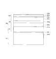
- the translucent substrate with an infrared reflecting function is laminated on a translucent substrate layer 10 disposed so as to separate the room from the outdoor, and on the indoor surface of the translucent substrate layer 10.
- the thickness of the translucent substrate layer 10 is shown smaller than the actual thickness with respect to the thickness of the infrared reflective functional layer 20.
- the solar absorptivity of the translucent substrate layer 10 according to the present embodiment is 30% or more.
- green glass, smoked glass, or the like having high solar absorptance is employed.
- green glass, smoked glass or the like is employed as the translucent substrate layer 10, but is not limited thereto, and may be a resin substrate such as resin glass, for example.
- the solar radiation absorption rate may be 30% or more, but may be 40% or more, or 50% or more, for example.
- the infrared reflective functional layer 20 is an infrared reflective film that is laminated (attached) to the indoor surface of the translucent substrate layer 10.
- the infrared reflection functional layer 20 includes a reflection layer 22 for reflecting infrared rays, and a protective layer 23 laminated on the indoor side surface of the reflection layer 22. More specifically, the infrared reflective functional layer 20 has a layer structure in which a reflective layer 22 and a protective layer 23 are laminated in that order on one surface 21a of a base material 21, and an adhesive layer 24 is provided on the other surface 21b. It has become.
- the vertical emissivity of the surface of the infrared reflecting functional layer 20 on the protective layer 23 side is set to 0.50 or less based on the experimental results described later.
- the vertical emissivity of the surface of the infrared reflection functional layer 20 on the protective layer 23 side is preferably 0.40 or less, more preferably 0.30 or less.
- a polyester film is used as the substrate 21 .
- a film made of polyethylene terephthalate, polyethylene naphthalate, polypropylene terephthalate, polybutylene terephthalate, polycyclohexylene methylene terephthalate, or a mixed resin in which two or more of these are combined is used.
- a polyethylene terephthalate (PET) film is preferable from the viewpoint of performance, and a biaxially stretched polyethylene terephthalate (PET) film is particularly preferable.
- the reflection layer 22 is a vapor deposition layer formed on the surface (one surface) 21a of the base material 21 by vapor deposition.
- the method for forming the vapor deposition layer include physical vapor deposition (PVD) such as sputtering, vacuum vapor deposition, and ion plating.
- PVD physical vapor deposition
- the reflective layer 22 is formed on the base material 21 by heating and evaporating the vapor deposition material by a method such as resistance heating, electron beam heating, laser beam heating, arc discharge or the like in vacuum.
- Ion plating is a vapor deposition method that combines vacuum vapor deposition and sputtering. In this method, in a vacuum, the evaporation layer released by heating is ionized and accelerated in an electric field, and is deposited on the substrate 21 in a high energy state, whereby the reflective layer 22 is formed.
- the reflective layer 22 has a multilayer structure in which a semi-transparent metal layer 22a is sandwiched between a pair of transparent layers 22b and 22c.
- the reflective layer 22 is formed by depositing the transparent layer 22b on the surface (one surface) 21a of the substrate 21, and then forming the translucent metal layer 22a on the transparent layer 22b. Finally, a transparent layer 22c is deposited on the semitransparent metal layer 22a.
- Examples of the material for forming the translucent metal layer 22a include aluminum (Al), silver (Ag), silver alloys (MgAg, APC (AgPdCu), AgCu, AgAuCu, AgPd, AgAu, etc.), aluminum alloys (AlLi, AlCa, AlMg or the like) or a metal material in which two or more of these are combined is used.
- the translucent metal layer 22a may be formed in two or more layers using these metal materials.
- the transparent layers 22b and 22c are for imparting transparency to the reflective layer 22 and preventing the translucent metal layer 22a from deteriorating.
- ITO indium tin oxide
- ITO indium titanium oxide
- oxidized Oxides such as indium zinc (IZO), gallium zinc oxide (GZO), aluminum zinc oxide (AZO), and gallium indium oxide (IGO) are used.
- the protective layer 23 includes a resin layer 23a laminated on the reflective layer 22 and a hard coat layer 23b formed on the resin layer 23a, and is adhered to the reflective layer 22 using an adhesive. That is, the protective layer 23 has a multilayer structure including an adhesive layer 23c, a resin layer 23a, and a hard coat layer 23b in order from the reflective layer 22 side, and the hard coat layer 23b is an infrared reflective functional layer according to this embodiment. 20 surfaces (outermost layers).
- the resin layer 23a for example, an olefin film is used, and as the olefin film, for example, high density polyethylene obtained by singly or copolymerizing ethylene, low density polyethylene, linear low density polyethylene, propylene alone or A film made of copolymerized polypropylene, polymethylpentene, or a mixed resin in which two or more of these are combined is used.
- the resin layer 23a is preferably a polypropylene (PP) film, and particularly preferably a biaxially oriented polypropylene (OPP) film.
- the thickness of the resin layer 23a is preferably 5 to 30 ⁇ m.
- the resin layer 23a may be a layer having a cross-linked structure of polymers including the repeating unit A represented by the following chemical formula I.
- the resin layer 23a is preferably a layer containing a polymer containing at least any two or more of repeating units A, B and C represented by the following chemical formula II.
- R1 in Chemical Formula II H or a methyl group can be used.
- R2 to R5 in Chemical Formula II H and an alkyl group or alkenyl group having 1 to 4 carbon atoms can be used.
- hydrogenated nitrile rubber (HNBR) is composed of repeating units A, B and C, and H is used as R1 to R5.
- the repeating number k is preferably 10 to 1000.
- acrylonitrile (repeating unit D) and derivatives thereof as shown in Chemical Formula III
- alkyl having 4 carbon atoms (repeating unit E) and derivatives thereof
- butadiene And a copolymer of the repeating unit F1 or F2) and derivatives thereof.
- R6 represents H or a methyl group
- R7 to R18 represent H or an alkyl group having 1 to 4 carbon atoms.
- F1 and F2 represents a repeating unit in which butadiene is polymerized, and F1 is a main repeating unit.
- nitrile rubber or nitrile rubber which is a copolymer of acrylonitrile (repeating unit D) and its derivatives of formula III, 1,3-butadiene (repeating unit F1) and its derivatives.
- Hydrogenated nitrile rubber in which part or all of the double bond is hydrogenated may be used.
- the butadiene on the left side is bonded to the side to which the cyano group (—CN) of acrylonitrile is bonded, and the butadiene on the right side is formed to the side to which the cyano group (—CN) of acrylonitrile is not bonded.
- one repeating unit A, one repeating unit B, and two repeating units C are included.
- the repeating unit A includes a carbon atom in which the carbon atom on the right side of the butadiene on the left side is bonded to the cyano group (—CN) of acrylonitrile, and the repeating unit B is bonded to the cyano group (—CN) of acrylonitrile.
- the resin layer 23a is prepared by dissolving the above-described polymer in a solvent (with a crosslinking agent if necessary), preparing a solution, applying the solution on the reflective layer 22, and then drying the solution (solvent Is volatilized).
- a configuration in which the protective layer 23 does not have an adhesive layer may be employed.
- the solvent is a solvent in which the above-described polymer is soluble.
- a solvent such as methyl ethyl ketone (MEK) or methylene chloride (dichloromethane) is used.
- Methyl ethyl ketone and methylene chloride are low boiling point solvents (methyl ethyl ketone is 79.5 ° C., methylene chloride is 40 ° C.). Therefore, when these solvents are used, since the solvent can be volatilized at a low drying temperature, the base material 21 (or the reflective layer 22) is not damaged by heat.
- the thickness of the resin layer 23a is 1 ⁇ m or more as a lower limit. Preferably, it is 3 ⁇ m or more. Moreover, as an upper limit, it is 20 micrometers or less. Preferably, it is 15 ⁇ m or less. More preferably, it is 10 ⁇ m or less. If the thickness of the resin layer 23a is small, the infrared reflection characteristics are enhanced, but the scratch resistance is impaired, and the function as the protective layer 23a cannot be sufficiently exhibited. When the thickness of the resin layer 23a is large, the heat insulating property of the infrared reflective film is deteriorated. If the thickness of the resin layer 23a is within the above range, the resin layer 23a that can absorb the infrared rays and can appropriately protect the reflective layer 22 is obtained.
- L: m 5 to 25:60 to 90: 0 to 20 is more preferable
- k: l: m 15 to 25:65 to 85: 0 to 10 is more preferable.
- the resin layer 23a preferably has a cross-linked structure between polymers. Since the solvent resistance of the resin layer 23a is improved by cross-linking the polymers, the resin layer 23a is prevented from being eluted even when a solvent soluble in the polymer contacts the resin layer 23a. can do.
- the cumulative irradiation dose of the electron beam is 50 kGy or more as a lower limit value. Preferably, it is 100 kGy or more. More preferably, it is 200 kGy or more. Moreover, as an upper limit, it is 1000 kGy or less. Preferably, it is 600 kGy or less. More preferably, it is 400 kGy or less.
- the cumulative irradiation dose refers to the irradiation dose when the electron beam is irradiated once, and the total irradiation dose when the electron beam is irradiated a plurality of times.
- the single irradiation dose of the electron beam is preferably 300 kGy or less. If the integrated irradiation dose of the electron beam is within the above range, sufficient crosslinking between the polymers can be obtained. Moreover, if the integrated irradiation dose of the electron beam is within the above range, yellowing of the polymer and the substrate 1 generated by the electron beam irradiation can be minimized, and an infrared reflective film with less coloring can be obtained. Can do.
- These electron beam irradiation conditions are irradiation conditions at an acceleration voltage of 150 kV.
- a crosslinking agent such as a polyfunctional monomer such as a radical polymerization type monomer when the polymer is dissolved in the solvent or after the polymer is dissolved in the solvent.
- a polyfunctional monomer such as a radical polymerization type monomer
- radical polymerization monomers of (meth) acrylate monomers are preferred.
- the accumulated irradiation dose of the electron beam can be completed with a low irradiation dose. Moreover, since the cumulative irradiation dose of the electron beam is reduced, yellowing of the polymer and the substrate 21 can be further suppressed, and productivity can be improved.
- the amount of the additive added increases, the vertical emissivity of the surface of the infrared reflecting film on the resin layer 23a side (based on the reflective layer 22) deteriorates.
- the amount of the additive added is preferably 1 to 35% by weight with respect to the polymer. More preferably, it is 2 to 25% by weight based on the polymer.
- the hard coat layer 23b has transparency similar to the base material 21 and the resin layer 23a, and also has scratch resistance to prevent the surface from being scratched and scratched during cleaning and the like to reduce transparency.
- the hard coat layer 23b is not particularly limited as long as it exhibits sufficient scratch resistance (hardness) such as an ionizing radiation curable resin, a thermosetting resin, and a thermoplastic resin.
- the hard coat layer 23b is preferably an ionizing radiation curable resin such as an ultraviolet curable resin that is easy to form and easily increases the pencil hardness to a desired value.
- an ultraviolet curable acrylic-urethane hard coat is used as the ionizing radiation curable resin.
- the hard coat layer 23b is formed using an ionizing radiation curable resin
- the ionizing radiation curable resin is diluted as it is or with an organic solvent to an appropriate concentration, and the resulting solution is coated on the resin layer 23a with a coater.
- the hard coat layer 23b is formed by irradiating with ionizing radiation irradiation lamps for several seconds to several minutes.
- an organic solvent solution of the thermosetting resin is applied onto the resin layer 23a with a coating machine (coater), a release sheet is provided thereon, and a laminator or the like is provided. After deaeration, perform thermosetting and thermocompression bonding.
- the release sheet is not used, the hard coat layer 23b is formed by putting a drying step and evaporating the solvent before drying and heating so that the surface does not stick.
- the thickness of the hard coat layer 23b is preferably 0.5 to 10 ⁇ m.
- the adhesive layer 23c is formed using a polyester-based adhesive. And after forming the hard coat layer 23b on the olefin film used as the resin layer 23a, the polyester adhesive is apply
- the thickness of the adhesive layer 23c is preferably 0.1 to 1.5 ⁇ m.
- the translucent substrate with an infrared reflection function employs a two-layer structure of the resin layer 23 a and the hard coat layer 23 b as the protective layer 23.
- the hard coat layer 23b does not have better adhesion to the reflective layer 22 than the resin layer 23a (more precisely, the adhesive layer 23c). Accordingly, when the hard coat layer 23b is directly laminated on the reflective layer 22 without the resin layer 23a, water or the like enters from the interface between the reflective layer 22 and the hard coat layer 23b, and the reflective layer 22 deteriorates. It is assumed that the scratch resistance is impaired. However, since the hard coat layer 23b is formed through the resin layer 23a in the translucent substrate with an infrared reflection function according to the present embodiment, there is no such concern.
- the solar light transmittance is reduced by the infrared reflecting function layer 20, so that the light passes through the light-transmitting substrate layer 10 from the outside to the room.
- Directly incident sunlight can be suppressed.
- the translucent substrate layer 10 is transmitted, reflected, or absorbed by the translucent substrate layer 10. Will come to be.
- the infrared reflective functional layer 20 includes the protective layer 23, the reflective layer 22 having low scratch resistance is not exposed and can have good durability (scratch resistance).
- the inventors produced a light-transmitting substrate with an infrared reflecting function according to the above embodiment (Examples 1 to 4), and also produced a light-transmitting substrate with an infrared reflecting function for comparison.
- Examples 1 to 3 The production methods in Examples 1 to 3 are as follows. First, the reflective layer 22 is laminated on one surface 21a of the base material 21 by the DC magnetron sputtering method. Specifically, first, a transparent layer 22b is laminated on one surface 21a of the substrate 21 by a DC magnetron sputtering method, then a semi-transparent metal layer 22a is laminated by a DC magnetron sputtering method, and then DC magnetron sputtering.
- the transparent layer 22c is laminated by the method. Further, a hard coat agent is applied to the surface of the resin layer 23a (“acryl-urethane hard coat PC1097” manufactured by DIC) and cured by irradiating with ultraviolet rays to form the hard coat layer 23b. Then, a polyester-based adhesive is applied to the opposite surface of the resin layer 23a, and the laminate of the resin layer 23a / hard coat layer 23b is bonded to the surface of the reflective layer 22 via the adhesive layer 23c. Thus, the infrared reflective functional layer 20 was produced. The produced infrared reflective functional layer 20 was laminated on the translucent substrate layer (green glass) 10 via an adhesive layer to produce a translucent substrate with an infrared reflective function. Conditions such as the composition / component and thickness of each layer are shown in Table 1 below.
- Comparative Example 1 the manufacturing method in Comparative Example 1 is as follows. A PET layer was provided on the hard coat layer 23b of the infrared reflective functional layer 20 produced by the above production method via an adhesive layer. And the produced infrared reflective function layer 20 is laminated
- Example 1 A polyethylene terephthalate (PET) film having a thickness of 50 ⁇ m was used as the base material 21. Further, a transparent layer 22b made of indium tin oxide (ITO) is formed on the substrate 21 with a thickness of 35 nm, and a translucent metal layer 22a made of APC (AgPdCu) is formed thereon with a thickness of 11.5 nm. A transparent layer 22c made of indium tin oxide (ITO) was formed thereon with a thickness of 35 nm, and this was used as the reflective layer 22.
- PET polyethylene terephthalate
- ITO indium tin oxide
- APC AgPdCu
- a hard coat layer 23b is formed to a thickness of 1 ⁇ m on a resin layer 23a made of a biaxially oriented polypropylene (OPP) film having a thickness of 15 ⁇ m, and this is formed on the reflective layer 22 via an adhesive layer 23c having a thickness of 1 ⁇ m.
- the protective layer 23 was formed by laminating on the top.
- the produced infrared reflective functional layer 20 was laminated
- Example 2 A transparent layer 22b made of indium titanium oxide (ITO) is formed on the base material 21 with a thickness of 31 nm, and a translucent metal layer 22a made of APC (AgPdCu) is formed thereon with a thickness of 14 nm.
- Example 1 is the same as Example 1 except that a transparent layer 22c made of indium titanium oxide (ITO) is formed to a thickness of 31 nm.
- Example 3 A transparent layer 22b made of indium titanium oxide (ITO) is formed on the substrate 21 with a thickness of 31 nm, and a translucent metal layer 22a made of APC (AgPdCu) is formed thereon with a thickness of 18 nm.
- Example 1 is the same as Example 1 except that a transparent layer 22c made of indium titanium oxide (ITO) is formed to a thickness of 31 nm.
- Example 4 Using the same base material 21 as in Example 1, a transparent layer 22b made of indium zinc oxide (IZO) is formed on one surface 21a of the base material 21 with a thickness of 30 nm, and AP (AgPd) is made thereon. A semi-transparent metal layer 22a was formed with a thickness of 14 nm, and a transparent layer 22c made of indium zinc oxide (IZO) was formed thereon with a thickness of 30 nm. A resin layer 23a was formed on the reflective layer 22 by a coating method.
- IZO indium zinc oxide
- a hydrogenated nitrile rubber (trade name “Terban 5065” manufactured by LANXESS [k: 33.3, l: 63, m: 3.7, R1 to R3: H] is manufactured on the reflective layer 22.
- a 10% methyl ethyl ketone (MEK) solution was applied using an applicator, placed in an air-circulating drying oven, and dried for 2 minutes at 120 ° C.
- MEK methyl ethyl ketone
- the electron beam was irradiated from the surface side of the resin layer using an electron beam irradiation apparatus (product name “EC250 / 30/20 mA” manufactured by Iwasaki Electric Co., Ltd.) to form the resin layer 23a.
- the line speed was 3 m / min, the acceleration voltage was 150 kV, and the irradiation dose was 100 kGy.
- the same hard coat layer 23b as in Example 1 was laminated in the same manner as in Example 1 to form the protective layer 23.
- substrate with an infrared reflective function was carried out similarly to Example 1, and produced the translucent board
- Example 1 is the same as Example 1 except that an adhesive layer is formed with a thickness of 25 ⁇ m on the hard coat layer 23b and a PET layer is formed with a thickness of 50 ⁇ m thereon.
- Example 3 is the same as Example 3 except that the protective layer 23 is not formed.
- the solar heat acquisition rate is based on the rate at which near infrared rays pass through the green glass 10 (sunlight transmittance) and the rate at which far infrared rays pass through the green glass 10 by re-radiation (sunlight absorption rate). ing. More specifically, the solar heat acquisition rate is the sum of the radiant flux of the solar radiation that is transmitted through the glass portion and the heat flux that is absorbed by the glass and transmitted to the indoor side, with respect to the solar radiation that is perpendicularly incident on the glass surface. , Expressed as the ratio of incident solar radiation to radiant flux. The visible light transmittance is expressed as a ratio of the transmitted light beam to the incident light beam with respect to the daylight beam incident perpendicularly to the glass surface.
- the solar transmittance, solar reflectance, solar absorption rate, and visible light transmittance were measured according to JIS R3106 using a Hitachi spectrophotometer U4100.
- the light incident surface was a glass surface.
- the method for measuring the vertical emissivity is as follows. Using a Fourier transform infrared spectroscopic (FT-IR) apparatus (manufactured by Varian) equipped with a variable angle reflection accessory, the regular reflectance of infrared light with a wavelength of 5 microns to 25 microns was measured, and JISR 3106-2008 It calculated
- the light incident surface was from the infrared reflective functional layer 20 side.
- the green glass 10 and the infrared reflection function are measured by measuring the vertical emissivity of the surface of the infrared reflection functional layer 20 on the protective layer 23 side of far infrared rays re-radiated from the infrared reflection functional layer 20 to the indoor side.
- the radiation characteristics of far infrared rays re-radiated from the layer 20 to the indoor side were examined. These results are shown in Table 1.
- each of Examples 1 to 4 and Comparative Examples 1 and 3 was subjected to a scratch resistance evaluation test.
- the first test and the second test were performed.
- a ten-point pen tester was used, steel wool (Bonster # 0000) was used as the rubbing means, and the rubbing means was brought into contact with the specimen (Examples and Comparative Examples).
- a test of reciprocating 10 times while applying a load of is performed.
- a Gakushin abrasion tester is used, and cloth (Kanakin No. 3) is used as the rubbing means.
- the rubbing means is brought into contact with the specimen (Example and Comparative Example), and a load of 500 g is used.
- the solar radiation absorption rates in the light-transmitting substrates with infrared reflection functions of Examples 1 to 4 were 50.2%, 50.5%, 56.4%, respectively. 51.9%, which is higher than the solar radiation absorption rate (35.4%) of the green glass 10 alone of Comparative Example 2.
- the visible light transmittances in the light-transmitting substrates with infrared reflection functions of Examples 1 to 4 are 68.8%, 67.6%, 57.6%, and 67.1%, which is lower than the visible light transmittance (81.0%) of the green glass 10 alone of Comparative Example 2.
- the vertical emissivity of the green glass 10 alone of Comparative Example 2 shows a value (0.88) significantly higher than 0.50, and the rate of re-radiation of far-infrared rays from the green glass 10 into the room is increased. Yes.
- the vertical emissivities of the light-transmitting substrates with infrared reflection functions of Examples 1 to 4 are values significantly lower than 0.50 (0.26, 0.22, 0.19, 0.12 respectively). ), The rate at which far-infrared rays are re-radiated from the green glass 10 to the outside increases.
- the ratio of re-radiation of far infrared rays from the green glass 10 into the room is low (the far infrared radiation characteristics are good) and good. Shows thermal insulation.
- the solar transmittance of the green glass 10 of Comparative Example 2 is 58.5%, whereas the solar transmittance of the light-transmitting substrates with infrared reflecting functions of Examples 1 to 4 is 39. 3%, 38.5%, 31.0%, and 36.3%.
- the translucent substrates with infrared reflection functions of Examples 1 to 4 by providing the infrared reflection functional layer 20 on the green glass 10, the solar radiation transmittance is significantly reduced as compared with the case of the green glass 10 alone. It has become. Therefore, the translucent substrates with infrared reflection functions of Examples 1 to 4 exhibit good reflection performance (heat shielding properties) of sunlight (near infrared rays).
- both the solar radiation transmittance and the vertical emissivity are better than those of the green glass 10 of Comparative Example 2 alone.
- the thickness of the semi-transparent metal layer 22a which consists of APC (AgPdCu) is thick ( 14 ⁇ m and 18 ⁇ m, respectively). Accordingly, in the translucent substrates with infrared reflection function of Examples 1, 2, and 3, the value of solar transmittance gradually decreases in that order (as the thickness of the semitransparent metal layer 22a increases) ( 39.3%, 38.5%, and 31.0%, respectively).
- the value of the vertical emissivity is also decreasing gradually in that order (as the thickness of the semi-transparent metal layer 22a becomes thick, respectively). 0.26, 0.22, 0.19). From these results, it can be seen that the thicker the translucent metal layer 22a, the lower the solar transmittance and the vertical emissivity, and the higher the effect of suppressing the temperature rise.
- the adhesion layer is formed in the thickness of 25 micrometers on the hard-coat layer 23b, and the PET layer is formed in the thickness of 50 micrometers on it. Therefore, although the solar radiation transmittance shows the same value as that of the translucent substrate with the infrared reflecting function of Examples 1 to 3, the vertical emissivity is a value significantly higher than 0.50 (0.85). Show. For this reason, in the translucent board
- Comparative Example 3 the solar transmittance, solar reflectance, solar absorption rate, solar heat acquisition rate, and visible light transmittance showed the same values as those of the light-transmitting substrates with infrared reflecting function of Examples 1 to 4.
- Comparative Example 3 since the protective layer 23 was not formed, the vertical emissivity shows a value significantly lower than 0.50 (0.03), but the reflective layer 20 with low scratch resistance is exposed. Therefore, as shown below, the problem of poor durability remains.
- Example 5 Two light vehicles of the same kind were prepared, and the infrared reflection functional layer (infrared reflection film) 20 used in Example 1 was attached to the indoor side of all the window glasses of the light vehicle. Then, the cooling intensity of the air conditioner installed in the vehicle was set to 5 out of 6 stages, and the air volume of the air conditioning was set to 5 out of 8 stages to circulate the inside air. Then, with the front of the light vehicle stopped toward the southwest, the mannequin is placed on the driver seat side of the rear seat, and the surface temperature of the mannequin is measured by thermography (in Table 2 and Table 3 below, the interior (thermography) Measured).
- the space temperature of about 5 cm indoor side from the driver seat side window of the rear seat (in Tables 2 and 3 below, referred to as the interior of the vehicle (at the window)) was measured with a thermocouple coated with aluminum foil.
- the temperature of the indoor side surface of the window (the surface of the infrared reflecting film 20 or the surface of the green glass 10) (in the following Tables 2 and 3, referred to as the vehicle interior (window surface)) was measured with a thermocouple. Note that the measurement was performed on August 11, 2011 at 13:30.
- Example 5 is the same as Example 5 except that the infrared reflective functional layer (infrared reflective film) 20 used in Comparative Example 1 is attached to the indoor side of all the window glasses of the minicar. These results are shown in Table 2.
- Example 5 is lower in the vehicle (thermography) and in the vehicle (by the window) than the result of Comparative Example 4.
- the infrared emissivity function used in Comparative Example 4 is the vertical emissivity (0.26) of the infrared reflective functional layer (infrared reflective film) 20 used in Example 5 (same as Example 1). It was confirmed that the temperature rise suppression effect in the vehicle (thermography) and in the vehicle (by the window) due to being significantly lower than the vertical emissivity (0.85) of the layer (infrared reflective film) 20 was high.
- Example 6 The same measurement as in Example 5 was performed except that the front of the light vehicle was stopped toward the south. The measurement was performed at 15:30 on August 14, 2011.
- Example 6 is the same as Example 6 except that the infrared reflective functional layer (infrared reflective film) 20 is not provided. These results are shown in Table 3.
- Example 6 since the infrared reflective functional layer (infrared reflective film) 20 used in Example 1 is affixed to the indoor side of all the window glass of the mini vehicle, the infrared reflective functional layer (infrared reflective film) 20 is used. Compared to Comparative Example 5 that was not provided, it was confirmed that the temperature rise suppression effect in the vehicle (thermography) and in the vehicle (by the window) due to low solar transmittance and vertical emissivity was high.
- the translucent substrate with an infrared reflecting function according to the present embodiment is formed to make it difficult to see the room from the outside through the translucent substrate layer, for example, for the purpose of providing privacy protection.
- the translucent substrate with an infrared reflecting function according to the present embodiment is disposed so as to separate the room from the outside, and the translucent substrate layer having a visible light transmittance of 50% or more, and the translucent substrate layer And an infrared reflection functional layer having a visible light transmittance of 50% or less, which is laminated on the indoor surface.
- the visible light transmittance of the translucent substrate layer is 50% or more, and the visible light transmittance of the infrared reflecting functional layer 20 is 50. Since the configuration is the same as that of the translucent substrate with the infrared reflection function according to the first embodiment except that it is% or less, the same configuration is denoted by the same reference numeral and detailed description is given. Do not repeat.
- the solar absorptivity of the translucent substrate layer according to this embodiment is 30% or more.
- Examples of such a translucent substrate layer include glass and a transparent resin substrate.
- a smoke film is employed for the infrared reflective functional layer according to the present embodiment.
- a smoke film is employed as the infrared reflection functional layer, but the present invention is not limited to this, and the visible light transmittance may be 50% or less.
- the infrared reflection functional layer includes a reflection layer for reflecting infrared rays, and a protective layer laminated on the indoor side surface of the reflection layer.
- the vertical emissivity of the protective layer side surface of the infrared reflective functional layer is set to 0.50 or less.
- the visible light transmittance of the translucent substrate layer according to the present embodiment is 50% or more as described above, and compared with the translucent substrate layer of the translucent substrate with infrared reflection function according to the first embodiment.
- the solar absorptivity of the translucent substrate layer itself is lowered, but the solar transmissivity of the translucent substrate layer itself is increased.
- solar radiation transmittance is reduced by the infrared reflective functional layer. Therefore, it is possible to suppress sunlight (near infrared rays) that is directly incident on the room from the outside through the light-transmitting substrate layer.
- the infrared reflective functional layer is formed on the translucent substrate layer.
- the solar radiation absorptivity is increased.
- far infrared rays absorbed by the translucent substrate layer from the translucent substrate layer to the indoor side Since re-radiant heat due to far-infrared rays re-radiated to the sun is suppressed, the temperature rise in the room can be suppressed.
- an infrared reflective functional layer with a low visible light transmittance is laminated on a light transmissive substrate layer with a high visible light transmittance, it is difficult to see the room from the outside through the light transmissive substrate layer, for example, providing privacy protection can do.
- substrate with an infrared reflective function which concerns on this invention is not limited to said each embodiment, A various change is possible in the range which does not deviate from the summary of this invention.
- the reflective layer 2 is formed by vapor deposition.
- the reflective layer is prepared separately from the base material, such as using a reflective film, and the reflective layer is attached to the base material. You may make it do.
- the infrared reflective functional layer (infrared reflective film) is laminated (attached) to the translucent substrate layer via the adhesive layer, but is not limited thereto.
- an infrared reflection functional layer may be directly formed on the light transmissive substrate layer.
- the protective layer is formed by laminating a hard coat layer on the resin layer, but the protective layer may be a resin layer, more specifically, an olefin resin layer alone, Only the hard coat layer may be used. However, from the viewpoint of scratch resistance, the protective layer preferably includes a hard coat layer.
- the resin layer is bonded to the surface of the reflective layer using an adhesive, but the present invention is not limited to this.
Landscapes
- Chemical & Material Sciences (AREA)
- Physics & Mathematics (AREA)
- General Chemical & Material Sciences (AREA)
- Life Sciences & Earth Sciences (AREA)
- Engineering & Computer Science (AREA)
- Chemical Kinetics & Catalysis (AREA)
- Geochemistry & Mineralogy (AREA)
- Materials Engineering (AREA)
- Organic Chemistry (AREA)
- Optics & Photonics (AREA)
- General Physics & Mathematics (AREA)
- Health & Medical Sciences (AREA)
- Toxicology (AREA)
- Laminated Bodies (AREA)
- Surface Treatment Of Glass (AREA)
Abstract
Priority Applications (6)
| Application Number | Priority Date | Filing Date | Title |
|---|---|---|---|
| EP13807056.0A EP2865519B1 (fr) | 2012-06-21 | 2013-06-21 | Substrat de transmission de lumière à fonction de réflexion de la lumière infrarouge |
| CN201380033062.6A CN104411486B (zh) | 2012-06-21 | 2013-06-21 | 带红外线反射功能的透光性基板 |
| ES13807056.0T ES2639557T3 (es) | 2012-06-21 | 2013-06-21 | Substrato de transmisión de luz con función de reflexión de luz infrarroja |
| US14/409,925 US9477023B2 (en) | 2012-06-21 | 2013-06-21 | Visible light-transmissive and infrared-reflective substrate |
| JP2014521527A JP6326368B2 (ja) | 2012-06-21 | 2013-06-21 | 赤外線反射機能付き透光性基板 |
| KR1020157001035A KR102041003B1 (ko) | 2012-06-21 | 2013-06-21 | 적외선 반사 기능이 있는 투광성 기판 |
Applications Claiming Priority (2)
| Application Number | Priority Date | Filing Date | Title |
|---|---|---|---|
| JP2012-140105 | 2012-06-21 | ||
| JP2012140105 | 2012-06-21 |
Publications (1)
| Publication Number | Publication Date |
|---|---|
| WO2013191285A1 true WO2013191285A1 (fr) | 2013-12-27 |
Family
ID=49768876
Family Applications (1)
| Application Number | Title | Priority Date | Filing Date |
|---|---|---|---|
| PCT/JP2013/067130 Ceased WO2013191285A1 (fr) | 2012-06-21 | 2013-06-21 | Substrat de transmission de lumière à fonction de réflexion de la lumière infrarouge |
Country Status (7)
| Country | Link |
|---|---|
| US (1) | US9477023B2 (fr) |
| EP (1) | EP2865519B1 (fr) |
| JP (1) | JP6326368B2 (fr) |
| KR (1) | KR102041003B1 (fr) |
| CN (1) | CN104411486B (fr) |
| ES (1) | ES2639557T3 (fr) |
| WO (1) | WO2013191285A1 (fr) |
Cited By (3)
| Publication number | Priority date | Publication date | Assignee | Title |
|---|---|---|---|---|
| KR20160066594A (ko) * | 2014-12-02 | 2016-06-13 | 삼성디스플레이 주식회사 | 편광 부재 및 이를 포함하는 표시 장치 |
| JP2016186627A (ja) * | 2015-03-27 | 2016-10-27 | 日立マクセル株式会社 | 透明スクリーン機能を備えた透明遮熱部材 |
| JP2020503545A (ja) * | 2016-12-16 | 2020-01-30 | スリーエム イノベイティブ プロパティズ カンパニー | 赤外線を反射する光学的に透明なアセンブリ及びその製造方法 |
Families Citing this family (5)
| Publication number | Priority date | Publication date | Assignee | Title |
|---|---|---|---|---|
| KR102799376B1 (ko) * | 2016-02-29 | 2025-04-23 | 도요보 가부시키가이샤 | 농업 하우스, 이 농업 하우스를 사용한 식물의 재배 방법 및 열선 반사 필름 구조체 |
| US10838126B2 (en) * | 2016-09-19 | 2020-11-17 | Apple Inc. | Electronic devices with infrared blocking filters |
| JP2019044461A (ja) * | 2017-08-31 | 2019-03-22 | 立川ブラインド工業株式会社 | 日射遮蔽装置およびスラット |
| KR102341650B1 (ko) * | 2017-09-28 | 2021-12-21 | 동우 화인켐 주식회사 | 포스 터치 센서 및 그 제조방법 |
| CN113739244A (zh) * | 2021-08-18 | 2021-12-03 | 浙江大学 | 一种可见光透明辐射散热组件 |
Citations (13)
| Publication number | Priority date | Publication date | Assignee | Title |
|---|---|---|---|---|
| JPS5810228B2 (ja) * | 1977-12-21 | 1983-02-24 | 帝人株式会社 | 積層体 |
| JPS6151762B2 (fr) * | 1979-05-10 | 1986-11-10 | Teijin Ltd | |
| JPH0710609A (ja) * | 1993-06-29 | 1995-01-13 | Central Glass Co Ltd | 熱遮断ガラスおよびそれを用いた複層ガラス |
| JPH07315889A (ja) * | 1994-03-30 | 1995-12-05 | Nippon Sheet Glass Co Ltd | 熱線遮蔽ガラスおよび熱線遮蔽ガラス複合体 |
| JPH11157881A (ja) * | 1997-09-18 | 1999-06-15 | Central Glass Co Ltd | 低放射ガラス積層体 |
| JP2001179887A (ja) | 1999-12-27 | 2001-07-03 | Teijin Ltd | 窓貼用熱線反射フィルム |
| JP2001310407A (ja) * | 2000-04-28 | 2001-11-06 | Teijin Ltd | 透明積層フィルム |
| JP2005343113A (ja) | 2004-06-07 | 2005-12-15 | Lintec Corp | 日射遮蔽フィルム及びその製造方法 |
| JP2011207223A (ja) * | 2010-03-12 | 2011-10-20 | Toray Ind Inc | 遠赤外線反射性積層体 |
| JP2012013965A (ja) * | 2010-06-30 | 2012-01-19 | Dainippon Printing Co Ltd | 選択波長反射フィルム |
| JP2012018228A (ja) * | 2010-07-06 | 2012-01-26 | Dainippon Printing Co Ltd | 選択波長反射フィルム |
| JP2012032759A (ja) * | 2010-06-30 | 2012-02-16 | Dainippon Printing Co Ltd | 選択波長反射フィルム |
| WO2013122227A1 (fr) * | 2012-02-16 | 2013-08-22 | 日東電工株式会社 | Procédé de fabrication d'un substrat réfléchissant les infrarouges |
Family Cites Families (12)
| Publication number | Priority date | Publication date | Assignee | Title |
|---|---|---|---|---|
| US4166876A (en) | 1977-03-28 | 1979-09-04 | Teijin Limited | Transparent, electrically conductive laminated structure and process for production thereof |
| US5956175A (en) * | 1998-07-31 | 1999-09-21 | Msc Specialty Films Inc | Solar control window film |
| US6602608B2 (en) * | 2001-11-09 | 2003-08-05 | Guardian Industries, Corp. | Coated article with improved barrier layer structure and method of making the same |
| EP1852402A1 (fr) * | 2004-12-06 | 2007-11-07 | Nippon Sheet Glass Company Limited | Élément de verre remplissant une fonction photocatalytique et une fontion de réflection de rayons thermiques et verre a double couche employant cet élément |
| EP1870386A4 (fr) | 2005-04-15 | 2009-01-28 | Asahi Glass Co Ltd | Plaque de verre avec couche formant bouclier infrarouge et son procede de fabrication |
| CN101288007A (zh) | 2005-10-26 | 2008-10-15 | 中央硝子株式会社 | 近红外线反射基板和利用该基板的近红外线反射层叠玻璃、近红外线反射双层玻璃 |
| WO2007049478A1 (fr) | 2005-10-26 | 2007-05-03 | Central Glass Company, Limited | Substrat reflechissant le rayonnement proche infrarouge et verre feuillete reflechissant le rayonnement proche infrarouge employant ce substrat, ainsi que verre double couche reflechissant le rayonnement proche infrarouge |
| CN100562767C (zh) | 2007-01-26 | 2009-11-25 | 日鹤实业股份有限公司 | 多层隔热膜贴片 |
| CN101156765A (zh) | 2007-11-07 | 2008-04-09 | 西安西川医疗器械有限公司 | 便携式电子内窥镜 |
| RU2559444C2 (ru) * | 2010-03-01 | 2015-08-10 | СиПиФИЛМЗ ИНК. | Оконные пленки с низким коэффициентом излучения и экранирующие эмп |
| CN201773236U (zh) | 2010-08-23 | 2011-03-23 | 潘彩玲 | 光能驱动变色膜 |
| KR101248597B1 (ko) | 2011-11-07 | 2013-03-28 | 한국전력기술 주식회사 | 태양광발전모듈의 적층시스템 |
-
2013
- 2013-06-21 CN CN201380033062.6A patent/CN104411486B/zh active Active
- 2013-06-21 KR KR1020157001035A patent/KR102041003B1/ko active Active
- 2013-06-21 US US14/409,925 patent/US9477023B2/en active Active
- 2013-06-21 JP JP2014521527A patent/JP6326368B2/ja active Active
- 2013-06-21 ES ES13807056.0T patent/ES2639557T3/es active Active
- 2013-06-21 WO PCT/JP2013/067130 patent/WO2013191285A1/fr not_active Ceased
- 2013-06-21 EP EP13807056.0A patent/EP2865519B1/fr active Active
Patent Citations (13)
| Publication number | Priority date | Publication date | Assignee | Title |
|---|---|---|---|---|
| JPS5810228B2 (ja) * | 1977-12-21 | 1983-02-24 | 帝人株式会社 | 積層体 |
| JPS6151762B2 (fr) * | 1979-05-10 | 1986-11-10 | Teijin Ltd | |
| JPH0710609A (ja) * | 1993-06-29 | 1995-01-13 | Central Glass Co Ltd | 熱遮断ガラスおよびそれを用いた複層ガラス |
| JPH07315889A (ja) * | 1994-03-30 | 1995-12-05 | Nippon Sheet Glass Co Ltd | 熱線遮蔽ガラスおよび熱線遮蔽ガラス複合体 |
| JPH11157881A (ja) * | 1997-09-18 | 1999-06-15 | Central Glass Co Ltd | 低放射ガラス積層体 |
| JP2001179887A (ja) | 1999-12-27 | 2001-07-03 | Teijin Ltd | 窓貼用熱線反射フィルム |
| JP2001310407A (ja) * | 2000-04-28 | 2001-11-06 | Teijin Ltd | 透明積層フィルム |
| JP2005343113A (ja) | 2004-06-07 | 2005-12-15 | Lintec Corp | 日射遮蔽フィルム及びその製造方法 |
| JP2011207223A (ja) * | 2010-03-12 | 2011-10-20 | Toray Ind Inc | 遠赤外線反射性積層体 |
| JP2012013965A (ja) * | 2010-06-30 | 2012-01-19 | Dainippon Printing Co Ltd | 選択波長反射フィルム |
| JP2012032759A (ja) * | 2010-06-30 | 2012-02-16 | Dainippon Printing Co Ltd | 選択波長反射フィルム |
| JP2012018228A (ja) * | 2010-07-06 | 2012-01-26 | Dainippon Printing Co Ltd | 選択波長反射フィルム |
| WO2013122227A1 (fr) * | 2012-02-16 | 2013-08-22 | 日東電工株式会社 | Procédé de fabrication d'un substrat réfléchissant les infrarouges |
Non-Patent Citations (1)
| Title |
|---|
| See also references of EP2865519A4 |
Cited By (4)
| Publication number | Priority date | Publication date | Assignee | Title |
|---|---|---|---|---|
| KR20160066594A (ko) * | 2014-12-02 | 2016-06-13 | 삼성디스플레이 주식회사 | 편광 부재 및 이를 포함하는 표시 장치 |
| KR102353632B1 (ko) * | 2014-12-02 | 2022-01-20 | 삼성디스플레이 주식회사 | 편광 부재 및 이를 포함하는 표시 장치 |
| JP2016186627A (ja) * | 2015-03-27 | 2016-10-27 | 日立マクセル株式会社 | 透明スクリーン機能を備えた透明遮熱部材 |
| JP2020503545A (ja) * | 2016-12-16 | 2020-01-30 | スリーエム イノベイティブ プロパティズ カンパニー | 赤外線を反射する光学的に透明なアセンブリ及びその製造方法 |
Also Published As
| Publication number | Publication date |
|---|---|
| EP2865519A1 (fr) | 2015-04-29 |
| US9477023B2 (en) | 2016-10-25 |
| KR102041003B1 (ko) | 2019-11-05 |
| ES2639557T3 (es) | 2017-10-27 |
| EP2865519A4 (fr) | 2016-01-20 |
| JPWO2013191285A1 (ja) | 2016-05-26 |
| CN104411486B (zh) | 2017-07-21 |
| CN104411486A (zh) | 2015-03-11 |
| JP6326368B2 (ja) | 2018-05-16 |
| EP2865519B1 (fr) | 2017-08-09 |
| US20150192716A1 (en) | 2015-07-09 |
| KR20150023769A (ko) | 2015-03-05 |
Similar Documents
| Publication | Publication Date | Title |
|---|---|---|
| JP6326368B2 (ja) | 赤外線反射機能付き透光性基板 | |
| JP5859476B2 (ja) | 赤外線反射フィルム | |
| JP2013010341A (ja) | 赤外線反射フィルム | |
| JP2011509193A5 (fr) | ||
| WO2016021543A1 (fr) | Film réfléchissant les infrarouges | |
| WO2013089185A1 (fr) | Film réfléchissant les infrarouges | |
| JP6155234B2 (ja) | 透光遮熱布 | |
| WO2013122227A1 (fr) | Procédé de fabrication d'un substrat réfléchissant les infrarouges | |
| JP6163196B2 (ja) | 赤外線反射フィルム | |
| JP2015001625A (ja) | 赤外線反射フィルム | |
| JP2014141015A (ja) | 積層フィルム | |
| JP2013144427A (ja) | 赤外線反射フィルム | |
| JPWO2013115233A1 (ja) | 赤外線反射フィルム | |
| WO2013115237A1 (fr) | Procédé de fabrication de matériau de base à coefficient de frottement réduit | |
| JP2013144426A (ja) | 赤外線反射フィルム | |
| JP2015001624A (ja) | 赤外線反射フィルム | |
| JP2013145357A (ja) | 赤外線反射フィルム | |
| CN121079347A (zh) | 层叠体和包含其的功能性膜 | |
| JP2020049757A (ja) | 光学用光透過性積層体および光学用光透過性積層体の製造方法 | |
| JP2013257391A (ja) | 赤外線反射フィルムの製造方法 |
Legal Events
| Date | Code | Title | Description |
|---|---|---|---|
| 121 | Ep: the epo has been informed by wipo that ep was designated in this application |
Ref document number: 13807056 Country of ref document: EP Kind code of ref document: A1 |
|
| ENP | Entry into the national phase |
Ref document number: 2014521527 Country of ref document: JP Kind code of ref document: A |
|
| WWE | Wipo information: entry into national phase |
Ref document number: 14409925 Country of ref document: US |
|
| NENP | Non-entry into the national phase |
Ref country code: DE |
|
| REEP | Request for entry into the european phase |
Ref document number: 2013807056 Country of ref document: EP |
|
| WWE | Wipo information: entry into national phase |
Ref document number: 2013807056 Country of ref document: EP |
|
| ENP | Entry into the national phase |
Ref document number: 20157001035 Country of ref document: KR Kind code of ref document: A |