WO2014002264A1 - Dispositif d'émission de lumière pour boîte de rangement - Google Patents
Dispositif d'émission de lumière pour boîte de rangement Download PDFInfo
- Publication number
- WO2014002264A1 WO2014002264A1 PCT/JP2012/066746 JP2012066746W WO2014002264A1 WO 2014002264 A1 WO2014002264 A1 WO 2014002264A1 JP 2012066746 W JP2012066746 W JP 2012066746W WO 2014002264 A1 WO2014002264 A1 WO 2014002264A1
- Authority
- WO
- WIPO (PCT)
- Prior art keywords
- light emitting
- light
- emitting panel
- organic
- panel
- Prior art date
- Legal status (The legal status is an assumption and is not a legal conclusion. Google has not performed a legal analysis and makes no representation as to the accuracy of the status listed.)
- Ceased
Links
Images







Classifications
-
- B—PERFORMING OPERATIONS; TRANSPORTING
- B60—VEHICLES IN GENERAL
- B60Q—ARRANGEMENT OF SIGNALLING OR LIGHTING DEVICES, THE MOUNTING OR SUPPORTING THEREOF OR CIRCUITS THEREFOR, FOR VEHICLES IN GENERAL
- B60Q3/00—Arrangement of lighting devices for vehicle interiors; Lighting devices specially adapted for vehicle interiors
- B60Q3/50—Mounting arrangements
- B60Q3/57—Retractable or concealable lighting devices
-
- B—PERFORMING OPERATIONS; TRANSPORTING
- B60—VEHICLES IN GENERAL
- B60Q—ARRANGEMENT OF SIGNALLING OR LIGHTING DEVICES, THE MOUNTING OR SUPPORTING THEREOF OR CIRCUITS THEREFOR, FOR VEHICLES IN GENERAL
- B60Q3/00—Arrangement of lighting devices for vehicle interiors; Lighting devices specially adapted for vehicle interiors
- B60Q3/20—Arrangement of lighting devices for vehicle interiors; Lighting devices specially adapted for vehicle interiors for lighting specific fittings of passenger or driving compartments; mounted on specific fittings of passenger or driving compartments
- B60Q3/225—Small compartments, e.g. glove compartments
-
- F—MECHANICAL ENGINEERING; LIGHTING; HEATING; WEAPONS; BLASTING
- F21—LIGHTING
- F21V—FUNCTIONAL FEATURES OR DETAILS OF LIGHTING DEVICES OR SYSTEMS THEREOF; STRUCTURAL COMBINATIONS OF LIGHTING DEVICES WITH OTHER ARTICLES, NOT OTHERWISE PROVIDED FOR
- F21V33/00—Structural combinations of lighting devices with other articles, not otherwise provided for
-
- F—MECHANICAL ENGINEERING; LIGHTING; HEATING; WEAPONS; BLASTING
- F21—LIGHTING
- F21Y—INDEXING SCHEME ASSOCIATED WITH SUBCLASSES F21K, F21L, F21S and F21V, RELATING TO THE FORM OR THE KIND OF THE LIGHT SOURCES OR OF THE COLOUR OF THE LIGHT EMITTED
- F21Y2105/00—Planar light sources
Definitions
- the present invention relates to a light emitting device for a storage box that illuminates the inside of the storage box.
- a vehicle is usually provided with a storage box for storing storage items such as small items.
- a storage box for a vehicle for example, an accessory case located in front of a passenger seat on a front panel of a vehicle is generally used. Techniques for illuminating the interior of such an accessory box have been proposed in prior art documents such as Patent Document 1.
- an organic EL (electroluminescence) illumination device is provided on an opening / closing lid that opens and closes the accessory case, and the organic EL illumination device emits light when the opening / closing lid is opened. Illumination of the glove compartment is performed.
- the organic EL lighting device emits light on both sides, it is also used as a vehicle interior lamp that illuminates the vehicle interior when the open / close lid is closed.
- the accessory case lighting device of the prior art as disclosed in Patent Document 1 is suitable for illumination inside the accessory case, but the accessory case is located in the lower part of the passenger compartment such as in front of the passenger seat. Therefore, there is a problem that the entire vehicle interior cannot be sufficiently illuminated.
- the problem to be solved by the present invention is the light emitting device for a storage box that can sufficiently illuminate not only the interior of the storage box such as an accessory case but also the surroundings of the storage box. It is an object of the present invention to provide
- a light-emitting device for a storage box is a light-emitting device that illuminates the interior of a storage box having a storage space having an opening for taking in and out stored items.
- the surface light emitting panel is movably held so that the surface light emitting panel projects outside from the opening and illuminates the outside of the storage box.
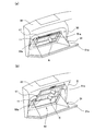
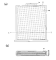
- FIG. 1 It is a perspective view which shows the light-emitting device for accessory cases of Example 1 of this invention. It is the front view and sectional drawing of the organic electroluminescent light emission panel in the light-emitting device of FIG. It is a block diagram which shows the drive control system which drives the organic electroluminescent light emission panel in the light-emitting device of FIG. It is a perspective view which each shows the illumination state in the accessory case by the light-emitting device of FIG. 1, and the illumination state in a vehicle interior. It is a perspective view which shows the light-emitting device for accessory cases of Example 2 of this invention. It is a front view of the organic electroluminescent light emission panel in the light-emitting device of FIG. FIG.
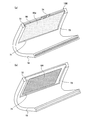
- FIG. 6 is a block diagram showing a drive control system for driving an organic EL light emitting panel in the light emitting device of FIG. 5. It is a perspective view which each shows the illumination state in the accessory case by the light-emitting device of FIG. 5, and the illumination state in a vehicle interior. It is a perspective view which shows the light-emitting device for accessory cases of Example 3 of this invention. It is the front view and sectional drawing of the organic electroluminescent light emission panel in the light-emitting device of FIG. It is a perspective view which each shows the illumination state in the accessory case by the light-emitting device of FIG. 9, and the illumination state in a vehicle interior. It is a perspective view which shows the light-emitting device for accessory cases of Example 4 of this invention.
- the holder 11 has a light emitting opening 13 on the front surface thereof so that the light emitting surface 12a of the organic EL light emitting panel 12 is exposed to the outside when the organic EL light emitting panel 12 is housed inside.
- the light exit opening 13 has substantially the same shape as the rectangular shape of the actual light emitting region of the light emitting surface 12a of the organic EL light emitting panel 12.
- the rear surface of the holder 11 is an attachment surface (not shown) attached to the interior of the accessory case of the vehicle.
- the holder 11 holds the organic EL light emitting panel 12 movably in the direction along the plane, and also pulls out the organic EL light emitting panel 12 from the holder 11 along the light emitting surface 12a in the moving direction.
- a drawer opening 15 communicating with the internal space is provided.
- the drawer opening 15 corresponds to the upper side surface among the four side surfaces between the front surface and the rear surface of the holder 11 and communicates with the light emitting opening portion 13.
- the remaining outer peripheral portion of the front surface of the holder 11 other than the light emitting opening 13 serves as a holding portion 14.
- the holding portion 14 has a U-shaped cross section including the back surface and the side surface portion of the outer peripheral portion of the holder 11.
- the organic EL light emitting panel 12 is slidably held when the edge of the organic EL light emitting panel 12 enters the inside of the U-shaped holding portion 14.
- the organic EL light emitting panel 12 In the state where the organic EL light emitting panel 12 is housed in the holder 11, as shown in FIG. 1, the upper portion of the organic EL light emitting panel 12 protrudes slightly from the drawer opening 15 to the outside. Further, the organic EL light emitting panel 12 has a handle 16 (operation unit) at the upper portion as shown in FIGS. 1 and 2A. The handle 16 is used when the organic EL light emitting panel 12 is pulled out. A stopper mechanism for preventing further movement of the organic EL light emitting panel 12 when the organic EL light emitting panel 12 is pulled out from the holder 11 and most of the light emitting surface 12a is located above the light emitting opening 13 is provided with the holder 11 and It may be provided in at least one of the organic EL light emitting panels 12.
- the holder 11 may have a mechanism for holding the organic EL light-emitting panel 12 in a state where movement of the organic EL light-emitting panel 12 is stopped at an arbitrary movement position.
- the inside of the organic EL light emitting panel 12 is shown in FIG. 2 (b) as a cross-section of the XY portion of FIG. 2 (a), and an organic function including a transparent electrode anode 22 and a light emitting layer on a transparent substrate 21.
- the layer 23, the metal electrode cathode 24, and the sheet-like transparent member 25 are sequentially laminated.
- the anode 22, the organic functional layer 23, and the cathode 24 are organic EL elements, and a plurality of these organic EL elements may be formed on the transparent substrate 21.
- the above-described laminated portion of the organic EL light emitting panel 12 is covered with a protective material 27 made of a resin having optical transparency. Although not shown between the laminated portion and the protective material 27, an adhesive may be filled.
- FIG. 3 shows the configuration of the drive control system 40 of the light emitting device 10 of FIG.
- the drive control system 40 drives the organic EL light-emitting panel 12 using a vehicle battery 41 as a power source.
- the brass terminal of the battery 41 is connected to a DC-DC converter 43 via an on / off switch 42.
- the negative terminal of the battery 41 is grounded.
- the on / off switch 42 is a switch that interlocks with opening / closing of an opening / closing lid 31a of the accessory case 31 described later. That is, the on / off switch 42 is turned off when the opening / closing lid 31a is closed, and the on / off switch 42 is turned on when the opening / closing lid 31a is opened.
- the DC-DC converter 43 converts the output DC voltage of the battery 41 into a drive voltage for the organic EL light emitting panel 12.
- a drive circuit 44 is connected to the output of the DC-DC converter 43.
- the drive circuit 44 includes, for example, a power transistor, and supplies a desired drive current between the anode 22 and the cathode 24 of the organic EL light emitting panel 12 using the output voltage of the DC-DC converter 43.
- the drive control system 40 and each of the anode 22 and the cathode 24 of the organic EL light emitting panel 12 are connected via a cord (connection means) not shown. Note that the cord has a sufficient length so that the organic EL light-emitting panel 12 can slide in the holder 11.
- connection between the drive control system 40 and each of the anode 22 and the cathode 24 of the organic EL light emitting panel 12 does not use the above-described cord, and the holder 11 does not move even if the organic EL light emitting panel 12 slides inside the holder 11.
- a contact mechanism (not shown) that maintains electrical contact for each of the anode 22 and the cathode 24 may be provided between the organic EL light emitting panel 12 and the organic EL light emitting panel 12.
- the accessory case 31 is a storage box located in front of the passenger seat on the front panel 32 of the vehicle.
- the accessory case 31 is integrated with an opening / closing lid 31a, and the opening / closing lid 31a is a door that opens and closes an opening for taking in and out stored items (accessories) in the accessory case 31. By pulling the opening / closing lid 31a toward the passenger seat, the opening / closing lid 31a is opened.
- the accessory case 31 is configured as a storage box having a V-shaped bowl-shaped storage space.
- the light emitting device 10 is attached to an inner wall surface (innermost wall surface at the innermost position) facing obliquely with respect to the inner wall surface on the opening / closing lid 31a side inside the accessory case 31.
- the attachment method may be fixed by an adhesive or a screw, or may be detachably attached by a mechanical attachment mechanism.
- the on / off switch 42 is turned on, and the drive current is supplied to the organic EL light emitting panel 12, so that the organic EL light emitting panel 12 emits light.
- the light is emitted in the direction of arrow A from the light emitting surface 12 a of the organic EL light emitting panel 12. Since the organic EL light emitting panel 12 is accommodated in the internal illumination position in the holder 11, the accommodation space in the accessory case 31 is illuminated by the emitted light.
- a user such as a vehicle occupant can operate the handle 16 to move the organic EL light-emitting panel 12 from the holder 11 in the direction of arrow B.
- the organic EL light emitting panel 12 moves to the position where the organic EL light emitting panel 12 protrudes outside through the opening of the accessory case 31, that is, the external lighting position, the external EL light emitting panel 12 reaches the external lighting position and is from the light emitting surface 12a of the organic EL light emitting panel 12.
- the emitted light is directed into the vehicle interior in the direction of arrow C, and the vehicle interior can be illuminated.
- FIG. 5 shows an accessory case light emitting device 50 according to a second embodiment of the present invention.
- the accessory case light emitting device 50 of Example 2 includes an organic EL light emitting panel 17 including a first light emitting region 51 a and a second light emitting region 52 a in the vertical direction of the light emitting surface 17 a.
- the organic EL light emitting panel 17 includes a first light emitting unit 51 corresponding to the upper first light emitting region 51a and a second light emitting unit 52 corresponding to the lower second light emitting region 52a.
- each of the first light-emitting portion 51 and the second light-emitting portion 52 has the same structure as that of the organic EL light-emitting panel 12 of Example 1 shown in FIG. 2B, description thereof is omitted here.
- the structure including the shape of the holder 11 of the light-emitting device 50 of FIG. 5 and the organic EL light-emitting panel 17 is the same as that of the light-emitting device 10 of FIG. 1, and the same reference numerals are used for the same portions.
- the drive control system 60 of the light emitting device 50 individually drives the two light emitting units 51 and 52 of the organic EL light emitting panel 17 using a vehicle battery 61 as a power source.
- the brass terminal of the battery 61 is connected to a DC-DC converter 63 via an on / off switch 62.
- the negative terminal of the battery 61 is grounded.
- the on / off switch 62 is a switch (open / close detection means) that is linked to the opening / closing of the opening / closing lid 31a. That is, the on / off switch 62 is turned off when the opening / closing lid 31a is closed, and the on / off switch 62 is turned on when the opening / closing lid 31a is opened.
- the DC-DC converter 63 converts the output DC voltage of the battery 61 into a drive voltage for the organic EL light emitting panel 17.
- Two drive circuits 64 a and 64 b are connected to the output of the DC-DC converter 63.
- Each of the drive circuits 64 a and 64 b includes, for example, a power transistor, and supplies a desired drive current between the anode and the cathode of each of the light emitting units 51 and 52 using the output voltage of the DC-DC converter 63.
- the drive control system 60 and each of the anodes and cathodes of the light emitting units 51 and 52 are connected via a cord.
- the cord has a sufficient length so that the organic EL light-emitting panel 17 can slide on the holder 11.
- the drive control system 60 has a drawer detection unit 65 and a control unit 66.
- the drawer detection unit 65 is a drawer detection unit that detects that the organic EL light-emitting panel 17 has been pulled out and moved to a predetermined drawer position (external illumination position) in the holder 11.
- a detection method by the drawer detection unit 65 a mechanical detection method, a magnetic detection method, or an optical detection method can be used.
- the drawer detection unit 65 of the mechanical detection method is turned on when pressed by the organic EL light-emitting panel 17 when the organic EL light-emitting panel 17 is present at the drawer position (external illumination position) of the holder 11, and is present at other positions. It consists of an on / off switch that is turned off.
- the organic EL light emitting panel 17 is brought out in a non-contact position using the photo interrupter 111 and the light detection hole 112 formed in the organic EL light emitting panel 17 as shown in FIG. It may be detected that it has been pulled out.
- the photo interrupter 111 is provided in the holder 11, and when light detection holes 112 are positioned in the groove 111 a of the photo interrupter 111, light emitted from a light emitting unit (not shown) of the photo interrupter 111 is passed through the light detection holes 112. Since the light receiving unit (not shown) of the photo interrupter 111 receives the light, it is detected that the organic EL light emitting panel 17 has reached the drawing position.
- the drawer position detected by the drawer detector 65 may include a range from the position where the organic EL light-emitting panel 17 is most pulled out in the holder 11 to a position in the storage direction.
- a control unit 66 is connected to the output of the drawer detection unit 65.
- the control unit 66 can be configured by a logic circuit, for example.
- the control unit 66 instructs the drive circuits 64a and 64b to drive in accordance with a signal indicating the detection result of the drawer detection unit 65. Specifically, when the drawer detection unit 65 detects that the organic EL light emitting panel 17 does not exist at the drawing position, a drive command is generated for the drive circuit 64a, and the drawer detection unit 65 generates the organic EL light emitting panel 17. Is detected at the pull-out position, a drive command is generated for both the drive circuits 64a and 64b.
- the accessory case light emitting device 50 is attached to the accessory case 31 of the vehicle as shown in FIG.
- the accessory case 31 is a storage box located in front of the front passenger seat of the front panel 32 of the vehicle.
- the light emitting device 50 is attached to a surface facing the opening / closing lid 31a side inside the accessory case 31 at an angle, and the attachment method is the same as in the first embodiment.
- the on / off switch 62 is turned on. Further, when the organic EL light emitting panel 17 is held at the internal illumination position of the holder 11 as shown in FIG. 8A, the organic EL light emitting panel 17 does not exist at the drawer position by the drawer detection unit 65. Thus, the control unit 66 generates a drive command for the drive circuit 64a. Since the drive circuit 64a supplies a drive current to the first light emitting unit 51 of the organic EL light emitting panel 17 in accordance with the drive command, the first light emitting unit 51 emits light, and the light is emitted from the first light emitting region of the organic EL light emitting panel 17.
- the light is emitted from 51a in the direction indicated by the arrow A. Therefore, the storage space inside the accessory case 31 is illuminated by the light emitted from the first light emitting region 51a.
- the controller 66 does not generate a drive command for the drive circuit 64b
- the drive circuit 64b does not drive the second light emitting unit 52 of the organic EL light emitting panel 17. Therefore, since the second light emitting unit 52 does not emit light, no light is emitted from the second light emitting region 52a. Since the light emitted from the first light emitting region 51a is sufficient for illumination inside the accessory case 31, which is a narrow storage space, energy saving can be achieved.
- a user such as a vehicle occupant can operate the handle 16 to move the organic EL light emitting panel 17 from the holder 11 in the direction of arrow B.
- the extraction detection unit 65 detects that the organic EL light emission panel 17 exists at the extraction position, and thereby the control unit 66 generates a drive command for the drive circuits 64a and 64b. Since the drive circuit 64a continuously supplies the drive current to the first light emitting unit 51 of the organic EL light emitting panel 17 according to the drive command, the light emission of the first light emitting unit 51 is maintained, and the light is emitted from the organic EL light emitting panel 17.
- the drive circuit 64b supplies a drive current to the second light emitting unit 52 of the organic EL light emitting panel 17 in accordance with the drive command, the second light emitting unit 52 emits light, and the light is emitted from the second light emitting region of the organic EL light emitting panel 17. Similarly, the light is emitted in the direction indicated by arrow C from 52a. Therefore, the emitted light from each of the first and second light emitting areas 51a and 52a of the organic EL light emitting panel 17 is directed into the vehicle interior, and the vehicle interior can be illuminated. Since the interior of the vehicle is illuminated by the light emitted from each of the first and second light emitting areas 51a and 52a, the interior can be illuminated brightly even in a large interior.
- FIG. 9 shows an accessory case light emitting device 70 of Example 3 of the present invention.
- the accessory case light emitting device 70 includes a holder 18 and an organic EL light emitting panel 19.
- the organic EL light emitting panel 19 is a quadrangular flexible panel (a panel having flexibility), and as shown in FIG. 10, one main surface thereof is a light emitting surface 19a that emits light to the outside, and the other main surface.
- a surface (not shown) is a sealing surface.
- the holder 18 is made of a synthetic resin and is formed in a curved shape in accordance with the shape of the bowl inside the accessory case 31 described above.
- a curved center line (not shown) is located at a position that bisects the holder 18 by a straight line in the lateral direction of the holder 18.
- the curved inner side of the holder 18 is the front side of the holder 18.
- the holder 18 is held in the internal space so that the light emitting surface 19 a of the organic EL light emitting panel 19 is
- the holder 18 has a light emitting opening 71 on the front surface thereof so that the light emitting surface 19a of the organic EL light emitting panel 19 is exposed to the outside when the organic EL light emitting panel 19 is held inside.
- the light emission opening 71 has substantially the same size as that of the upper light emitting surface 19a of the organic EL light emitting panel 19, for example, the upper half light emitting region.
- the rear surface of the holder 18 is an attachment surface (not shown) attached to the interior of the accessory case of the vehicle.
- the holder 18 holds the organic EL light-emitting panel 19 so as to be slidable in the vertical direction, and has a drawer opening 72 for pulling out the organic EL light-emitting panel 19 from the holder 18 in the sliding direction.
- the drawer opening 72 corresponds to the upper surface of the four side surfaces between the front surface and the rear surface of the holder 18 and communicates with the light emitting opening 71.
- the remaining part of the front surface of the holder 18 other than the light emitting opening 13 serves as a holding part 73 of the organic EL light emitting panel 19.
- the organic EL light-emitting panel 19 has a handle 74 at the upper portion as shown in FIGS. 9 and 10A.
- the handle 74 is used when pulling out the organic EL light emitting panel 19.
- a stopper mechanism for preventing further movement of the organic EL light emitting panel 19 when the organic EL light emitting panel 19 is pulled out from the holder 18 and most of the light emitting surface 19a is positioned above the light emitting opening 13 is provided with the holder 18 and It may be provided in at least one of the organic EL light emitting panels 19.
- the inside of the organic EL light emitting panel 19 is shown in FIG. 10 (b) as a cross-section of the XY portion of FIG. 10 (a).
- a transparent electrode anode 82 and a light emitting layer are provided on a flexible transparent substrate 81.
- the organic functional layer 83 includes a cathode 84 of a flexible metal electrode, and a sheet-like flexible transparent member 85 is sequentially laminated.
- the anode 82, the organic functional layer 83, and the cathode 84 are organic EL elements, and a plurality of these organic EL elements may be formed on the transparent substrate 81.
- the above-described laminated portion of the organic EL light-emitting panel 82 is covered with a flexible protective material 87 made of a resin having optical transparency. Although not shown between the laminated portion and the protective material 87, an adhesive may be filled.
- 10B shows the organic EL light-emitting panel 19 as a flat panel. However, the organic EL light-emitting panel 19 is curved when a force is applied from the outside, and when the force is removed, the curved shape is maintained as it is. It may be a panel having the property of returning to itself or a panel having the property of returning itself to a flat state.
- the drive control system 40 shown in FIG. 3 is used as it is.
- the drive circuit 44 supplies a desired drive current between the anode 82 and the cathode 84 of the organic EL light emitting panel 19 using the output voltage of the DC-DC converter 43.
- the light emitting device 10 is attached to the inner wall surface of the accessory case 31 on the side of the opening / closing lid 31a and the inner wall surface obliquely facing the inner wall surface.
- the attachment method may be fixed by an adhesive or a screw, or may be detachably attached by a mechanical attachment mechanism.
- the on / off switch 42 is turned on, and the drive current is supplied to the organic EL light emitting panel 19, so that the organic EL light emitting panel 19 emits light.
- the light is emitted in the direction indicated by the arrow A from the light emitting surface 19 a of the organic EL light emitting panel 19. Since the organic EL light emitting panel 19 is housed in the holder 18, a part of the light emitted from the light emitting surface 19 a illuminates the housing space inside the accessory case 31 through the light emitting opening 71. As shown in FIG.
- a user such as a vehicle occupant can operate the handle 74 to move the organic EL light-emitting panel 19 out of the holder 18 in the direction indicated by the arrow B.
- the organic EL light emitting panel 19 moves in this way, light is emitted in the direction indicated by the arrow C from the entire light emitting surface 19a of the organic EL light emitting panel 19. The emitted light is directed into the vehicle interior, and illumination of the vehicle interior can be performed.
- FIG. 12 shows an accessory case light emitting device 90 according to a fourth embodiment of the present invention.
- the accessory case light emitting device 90 includes a flexible organic EL light emitting panel 91 including a first light emitting region 92a and a second light emitting region 93a in the vertical direction of the light emitting surface 91a. ing. That is, the organic EL light emitting panel 91 includes a first light emitting unit (not shown) corresponding to the upper first light emitting region 92a and a second light emitting unit (not shown) corresponding to the lower second light emitting region 93a. .
- each of the first light-emitting part and the second light-emitting part has the same structure as that of the organic EL light-emitting panel 19 of Example 3 shown in FIG. 10B, description thereof is omitted here. Further, the configuration including the shape of the holder 18 of the light emitting device 90 and the organic EL light emitting panel 91 of FIG. 12 is the same as that of the light emitting device 70 of FIG. 9, and the same reference numerals are used for the same portions.
- the drive control system of the light emitting device 90 As the drive control system of the light emitting device 90, the drive control system 60 shown in FIG. 7 is used as it is.
- Each of the drive circuits 64a and 64b supplies a desired drive current between the anode and the cathode of each light emitting unit using the output voltage of the DC-DC converter 63.
- the light emitting device 90 is attached to the accessory case 31 of the vehicle as shown in FIG.
- the accessory case 31 is a storage box located in front of the front passenger seat of the front panel 32 of the vehicle.
- the light emitting device 90 is attached to the inner wall surface of the accessory case 31 on the opening / closing lid 31a side and the inner wall surface obliquely facing the inner wall surface, and the attachment method is the same as in the third embodiment.
- the on / off switch 62 is turned on. 14A, when the organic EL light emitting panel 91 is held at the internal illumination position by the holder 18, the organic EL light emitting panel 91 is not present at the drawer position by the drawer detection unit 65. Accordingly, the control unit 66 generates a drive command for the drive circuit 64a. Since the drive circuit 64a supplies a drive current to the first light emitting unit of the organic EL light emitting panel 91 in response to the drive command, the first light emitting unit emits light, and the light is emitted from the first light emitting region 92a of the organic EL light emitting panel 19. The light is emitted in the direction indicated by arrow A.
- the storage space inside the accessory case 31 is illuminated by the light emitted from the first light emitting region 92a.
- the control unit 66 does not generate a drive command for the drive circuit 64b
- the drive circuit 64b does not drive the second light emitting unit of the organic EL light emitting panel 91. Therefore, since the second light emitting unit does not emit light, no light is emitted from the second light emitting region 93a. Since the light emitted from the first light emitting region 92a is sufficient for illumination inside the accessory case 31, which is a narrow storage space, energy saving can be achieved.
- a user such as a vehicle occupant can operate the handle 74 to pull out the organic EL light emitting panel 91 from the holder 18 and move it in the direction indicated by the arrow B.
- the extraction detecting unit 65 detects that the organic EL light emitting panel 91 exists at the extraction position, and thereby the control unit 66 generates a drive command for the drive circuits 64a and 64b.
- the drive circuit 64a continuously supplies a drive current to the first light emitting unit of the organic EL light emitting panel 91 in response to the drive command, the light emission of the first light emitting unit is maintained, and the light is emitted from the organic EL light emitting panel 91.
- the light is emitted from one light emitting region 92a in a direction indicated by an arrow C.
- the drive circuit 64b supplies a drive current to the second light emitting unit of the organic EL light emitting panel 91 in response to the drive command, the second light emitting unit emits light, and the light is emitted from the second light emitting region 93a of the organic EL light emitting panel 91. Similarly, the light is emitted in the direction indicated by the arrow C.
- the emitted light from each of the first and second light emitting regions 92a and 93a of the organic EL light emitting panel 91 is directed into the vehicle interior, and the vehicle interior can be illuminated. Since the interior of the vehicle is illuminated by the light emitted from each of the first and second light emitting regions 92a and 93a, the interior can be illuminated brightly even in a large interior.
- FIGS. 15 (a) and 15 (b) show a light-emitting device 100 for putting accessories of Example 5 of the present invention.
- a light reflecting plate 101 is added to the light emitting device 70 shown as the third embodiment.
- the light reflecting plate 101 is disposed on the inner wall surface of the holder 18 facing the light emission opening 71.
- the organic EL light emitting panel 99 is not held, the light emission opening 71 is formed. Exposed to the outside.
- the light reflecting plate 101 has the same size as the light emitting opening 71.
- the light reflecting plate 101 may be formed by attaching a metal plate such as an aluminum plate or a silver plate to the inner wall surface of the holder 18 or may be formed by performing a metal plating process on the inner wall surface of the holder 18.
- the organic EL light emitting panel 99 has a light emitting surface 99b (FIG. 17B) on the opposite surface in addition to the light emitting surface 99a.
- the inside of the organic EL light emitting panel 99 is shown in FIG. 16 (b) as a cross-section of the XY portion of FIG. 16 (a).
- the transparent electrode anode 82 and the light emitting layer are provided on the flexible transparent substrate 81.
- the organic functional layer 83 includes a cathode 84a of a flexible transparent electrode, and a sheet-like flexible transparent member 85 are sequentially stacked.
- the anode 82, the organic functional layer 83, and the cathode 84 a are organic EL elements, and a plurality of these organic EL elements may be formed on the transparent substrate 81.
- the organic EL light emitting panel 99 of Example 5 emits light on both sides because the cathode 84a is formed of a flexible transparent material.
- the on / off switch 42 is turned on and a driving current is supplied to the organic EL light emitting panel 99.
- the light emitting panel 99 emits light.
- Light emitted from the anode 82 side of the organic functional layer 83 is emitted in the direction indicated by the arrow A from one light emitting surface 99a.
- a part of the light emitted from the cathode 84 a side of the organic functional layer 83 is reflected by the light reflecting plate 101, passes through the organic EL light emitting panel 99, and is emitted from one light emitting surface 99 a. Since the organic EL light emitting panel 99 is housed in the holder 18, a part of the emitted light on the light emitting surface 99 a illuminates the interior of the accessory case 31 through the light emitting opening 71.
- a user such as a vehicle occupant can operate the handle 74 to move the organic EL light-emitting panel 99 out of the holder 18.
- the organic EL light emitting panel 99 moves in this way, light is emitted from both light emitting surfaces 99a and 99b of the organic EL light emitting panel 19, so that the emitted light is not only in the accessory case 31 indicated by the arrow C, but also in the arrow D.
- the vehicle interior can be illuminated in a wide range.
- the light emitting device for compartment accessory is shown, but the present invention is not limited to this and can be applied to a storage box such as a furniture drawer. Further, the present invention is not limited to a storage box for a vehicle such as an automobile or a two-wheeled vehicle, but can be applied to a storage box for a vehicle such as a ship or an airplane.
- the organic EL light-emitting panel is shown as the surface light-emitting panel, but the configuration of the organic EL light-emitting panel is not limited to that shown in the embodiment.
- the present invention may use a light emitting panel other than the organic EL light emitting panel, for example, a light emitting panel in which a plurality of light emitting elements are arranged to enable surface light emission.
Landscapes
- Engineering & Computer Science (AREA)
- Mechanical Engineering (AREA)
- Arrangements Of Lighting Devices For Vehicle Interiors, Mounting And Supporting Thereof, Circuits Therefore (AREA)
Priority Applications (1)
| Application Number | Priority Date | Filing Date | Title |
|---|---|---|---|
| PCT/JP2012/066746 WO2014002264A1 (fr) | 2012-06-29 | 2012-06-29 | Dispositif d'émission de lumière pour boîte de rangement |
Applications Claiming Priority (1)
| Application Number | Priority Date | Filing Date | Title |
|---|---|---|---|
| PCT/JP2012/066746 WO2014002264A1 (fr) | 2012-06-29 | 2012-06-29 | Dispositif d'émission de lumière pour boîte de rangement |
Publications (1)
| Publication Number | Publication Date |
|---|---|
| WO2014002264A1 true WO2014002264A1 (fr) | 2014-01-03 |
Family
ID=49782487
Family Applications (1)
| Application Number | Title | Priority Date | Filing Date |
|---|---|---|---|
| PCT/JP2012/066746 Ceased WO2014002264A1 (fr) | 2012-06-29 | 2012-06-29 | Dispositif d'émission de lumière pour boîte de rangement |
Country Status (1)
| Country | Link |
|---|---|
| WO (1) | WO2014002264A1 (fr) |
Cited By (2)
| Publication number | Priority date | Publication date | Assignee | Title |
|---|---|---|---|---|
| JP2018174160A (ja) * | 2018-08-03 | 2018-11-08 | 株式会社小糸製作所 | 灯具 |
| JP2019212641A (ja) * | 2019-09-18 | 2019-12-12 | パイオニア株式会社 | 発光装置 |
Citations (4)
| Publication number | Priority date | Publication date | Assignee | Title |
|---|---|---|---|---|
| JPS5562441U (fr) * | 1978-10-23 | 1980-04-28 | ||
| JPH0423538U (fr) * | 1990-06-20 | 1992-02-26 | ||
| JP2005177084A (ja) * | 2003-12-18 | 2005-07-07 | Toyota Industries Corp | 照明装置付き鏡及びサンバイザー |
| JP2007137234A (ja) * | 2005-11-17 | 2007-06-07 | Toyota Industries Corp | 車両用小物入れ |
-
2012
- 2012-06-29 WO PCT/JP2012/066746 patent/WO2014002264A1/fr not_active Ceased
Patent Citations (4)
| Publication number | Priority date | Publication date | Assignee | Title |
|---|---|---|---|---|
| JPS5562441U (fr) * | 1978-10-23 | 1980-04-28 | ||
| JPH0423538U (fr) * | 1990-06-20 | 1992-02-26 | ||
| JP2005177084A (ja) * | 2003-12-18 | 2005-07-07 | Toyota Industries Corp | 照明装置付き鏡及びサンバイザー |
| JP2007137234A (ja) * | 2005-11-17 | 2007-06-07 | Toyota Industries Corp | 車両用小物入れ |
Cited By (5)
| Publication number | Priority date | Publication date | Assignee | Title |
|---|---|---|---|---|
| JP2018174160A (ja) * | 2018-08-03 | 2018-11-08 | 株式会社小糸製作所 | 灯具 |
| JP2019212641A (ja) * | 2019-09-18 | 2019-12-12 | パイオニア株式会社 | 発光装置 |
| JP2021144941A (ja) * | 2019-09-18 | 2021-09-24 | パイオニア株式会社 | 発光装置 |
| JP2023053241A (ja) * | 2019-09-18 | 2023-04-12 | パイオニア株式会社 | 発光装置 |
| JP7450077B2 (ja) | 2019-09-18 | 2024-03-14 | パイオニア株式会社 | 発光装置 |
Similar Documents
| Publication | Publication Date | Title |
|---|---|---|
| US9738227B2 (en) | Storage assembly for vehicle center console | |
| US8870405B2 (en) | Drawer illumination device with magnetic reed switch | |
| JP4669552B2 (ja) | 照明構造 | |
| RU2015102987A (ru) | Устройство освещения | |
| TWI727406B (zh) | 照明組件及用於照亮存儲單元的方法 | |
| US10279664B1 (en) | Vehicle sunshade | |
| JP2017150274A (ja) | ドアハンドル | |
| WO2014002264A1 (fr) | Dispositif d'émission de lumière pour boîte de rangement | |
| JP2017007503A (ja) | アシストグリップ | |
| JP5484232B2 (ja) | 自動車用荷室仕切装置、及び、自動車用荷室照明装置 | |
| US7481548B2 (en) | Portable case | |
| JP6344706B2 (ja) | 昇降収納装置 | |
| EP3190329A1 (fr) | Élément d'éclairage auxiliaire à usages multiples | |
| JP7215598B2 (ja) | 電気機器及び電気機器システム | |
| JP2001151012A (ja) | 照明装置 | |
| JP2015157572A (ja) | 照明装置及び乗り物 | |
| JP2002307326A (ja) | 電動工具 | |
| JP6907037B2 (ja) | 乗物用の室内照明装置 | |
| JP6635509B2 (ja) | 照明付き車両用ドアハンドルプロテクターとその照明構造 | |
| GB2577179A (en) | Illumination for storage units | |
| WO2014002214A1 (fr) | Dispositif électroluminescent pouvant être fixé à une plaque de fenêtre translucide | |
| JP2011135917A (ja) | ミラーキャビネット照明装置 | |
| JP2007320355A (ja) | 車両用収容具 | |
| JP2005280594A (ja) | サイドバイザー | |
| JP5988188B2 (ja) | 表示装置 |
Legal Events
| Date | Code | Title | Description |
|---|---|---|---|
| 121 | Ep: the epo has been informed by wipo that ep was designated in this application |
Ref document number: 12880060 Country of ref document: EP Kind code of ref document: A1 |
|
| NENP | Non-entry into the national phase |
Ref country code: DE |
|
| 122 | Ep: pct application non-entry in european phase |
Ref document number: 12880060 Country of ref document: EP Kind code of ref document: A1 |
|
| NENP | Non-entry into the national phase |
Ref country code: JP |