WO2014002565A1 - Dispositif de commande d'imagerie, système d'enregistrement et support d'enregistrement - Google Patents
Dispositif de commande d'imagerie, système d'enregistrement et support d'enregistrement Download PDFInfo
- Publication number
- WO2014002565A1 WO2014002565A1 PCT/JP2013/060504 JP2013060504W WO2014002565A1 WO 2014002565 A1 WO2014002565 A1 WO 2014002565A1 JP 2013060504 W JP2013060504 W JP 2013060504W WO 2014002565 A1 WO2014002565 A1 WO 2014002565A1
- Authority
- WO
- WIPO (PCT)
- Prior art keywords
- unit
- image
- imaging
- comparison
- storage
- Prior art date
- Legal status (The legal status is an assumption and is not a legal conclusion. Google has not performed a legal analysis and makes no representation as to the accuracy of the status listed.)
- Ceased
Links
Images


Classifications
-
- A—HUMAN NECESSITIES
- A61—MEDICAL OR VETERINARY SCIENCE; HYGIENE
- A61B—DIAGNOSIS; SURGERY; IDENTIFICATION
- A61B1/00—Instruments for performing medical examinations of the interior of cavities or tubes of the body by visual or photographical inspection, e.g. endoscopes; Illuminating arrangements therefor
- A61B1/04—Instruments for performing medical examinations of the interior of cavities or tubes of the body by visual or photographical inspection, e.g. endoscopes; Illuminating arrangements therefor combined with photographic or television appliances
- A61B1/041—Capsule endoscopes for imaging
-
- A—HUMAN NECESSITIES
- A61—MEDICAL OR VETERINARY SCIENCE; HYGIENE
- A61B—DIAGNOSIS; SURGERY; IDENTIFICATION
- A61B1/00—Instruments for performing medical examinations of the interior of cavities or tubes of the body by visual or photographical inspection, e.g. endoscopes; Illuminating arrangements therefor
- A61B1/00002—Operational features of endoscopes
- A61B1/00004—Operational features of endoscopes characterised by electronic signal processing
- A61B1/00009—Operational features of endoscopes characterised by electronic signal processing of image signals during a use of endoscope
-
- A—HUMAN NECESSITIES
- A61—MEDICAL OR VETERINARY SCIENCE; HYGIENE
- A61B—DIAGNOSIS; SURGERY; IDENTIFICATION
- A61B1/00—Instruments for performing medical examinations of the interior of cavities or tubes of the body by visual or photographical inspection, e.g. endoscopes; Illuminating arrangements therefor
- A61B1/00002—Operational features of endoscopes
- A61B1/00011—Operational features of endoscopes characterised by signal transmission
- A61B1/00016—Operational features of endoscopes characterised by signal transmission using wireless means
-
- A—HUMAN NECESSITIES
- A61—MEDICAL OR VETERINARY SCIENCE; HYGIENE
- A61B—DIAGNOSIS; SURGERY; IDENTIFICATION
- A61B1/00—Instruments for performing medical examinations of the interior of cavities or tubes of the body by visual or photographical inspection, e.g. endoscopes; Illuminating arrangements therefor
- A61B1/00002—Operational features of endoscopes
- A61B1/00011—Operational features of endoscopes characterised by signal transmission
- A61B1/00018—Operational features of endoscopes characterised by signal transmission using electrical cables
-
- A—HUMAN NECESSITIES
- A61—MEDICAL OR VETERINARY SCIENCE; HYGIENE
- A61B—DIAGNOSIS; SURGERY; IDENTIFICATION
- A61B1/00—Instruments for performing medical examinations of the interior of cavities or tubes of the body by visual or photographical inspection, e.g. endoscopes; Illuminating arrangements therefor
- A61B1/00002—Operational features of endoscopes
- A61B1/0002—Operational features of endoscopes provided with data storages
-
- A—HUMAN NECESSITIES
- A61—MEDICAL OR VETERINARY SCIENCE; HYGIENE
- A61B—DIAGNOSIS; SURGERY; IDENTIFICATION
- A61B1/00—Instruments for performing medical examinations of the interior of cavities or tubes of the body by visual or photographical inspection, e.g. endoscopes; Illuminating arrangements therefor
- A61B1/04—Instruments for performing medical examinations of the interior of cavities or tubes of the body by visual or photographical inspection, e.g. endoscopes; Illuminating arrangements therefor combined with photographic or television appliances
- A61B1/045—Control thereof
-
- G—PHYSICS
- G06—COMPUTING OR CALCULATING; COUNTING
- G06F—ELECTRIC DIGITAL DATA PROCESSING
- G06F16/00—Information retrieval; Database structures therefor; File system structures therefor
- G06F16/50—Information retrieval; Database structures therefor; File system structures therefor of still image data
- G06F16/51—Indexing; Data structures therefor; Storage structures
-
- G—PHYSICS
- G06—COMPUTING OR CALCULATING; COUNTING
- G06F—ELECTRIC DIGITAL DATA PROCESSING
- G06F18/00—Pattern recognition
- G06F18/20—Analysing
- G06F18/22—Matching criteria, e.g. proximity measures
-
- G—PHYSICS
- G06—COMPUTING OR CALCULATING; COUNTING
- G06F—ELECTRIC DIGITAL DATA PROCESSING
- G06F18/00—Pattern recognition
- G06F18/40—Software arrangements specially adapted for pattern recognition, e.g. user interfaces or toolboxes therefor
-
- G—PHYSICS
- G06—COMPUTING OR CALCULATING; COUNTING
- G06T—IMAGE DATA PROCESSING OR GENERATION, IN GENERAL
- G06T7/00—Image analysis
- G06T7/0002—Inspection of images, e.g. flaw detection
- G06T7/0012—Biomedical image inspection
-
- G—PHYSICS
- G06—COMPUTING OR CALCULATING; COUNTING
- G06T—IMAGE DATA PROCESSING OR GENERATION, IN GENERAL
- G06T7/00—Image analysis
- G06T7/0002—Inspection of images, e.g. flaw detection
- G06T7/0012—Biomedical image inspection
- G06T7/0014—Biomedical image inspection using an image reference approach
- G06T7/0016—Biomedical image inspection using an image reference approach involving temporal comparison
-
- G—PHYSICS
- G06—COMPUTING OR CALCULATING; COUNTING
- G06T—IMAGE DATA PROCESSING OR GENERATION, IN GENERAL
- G06T7/00—Image analysis
- G06T7/20—Analysis of motion
- G06T7/254—Analysis of motion involving subtraction of images
-
- G—PHYSICS
- G06—COMPUTING OR CALCULATING; COUNTING
- G06V—IMAGE OR VIDEO RECOGNITION OR UNDERSTANDING
- G06V10/00—Arrangements for image or video recognition or understanding
- G06V10/70—Arrangements for image or video recognition or understanding using pattern recognition or machine learning
- G06V10/74—Image or video pattern matching; Proximity measures in feature spaces
- G06V10/75—Organisation of the matching processes, e.g. simultaneous or sequential comparisons of image or video features; Coarse-fine approaches, e.g. multi-scale approaches; using context analysis; Selection of dictionaries
-
- G—PHYSICS
- G06—COMPUTING OR CALCULATING; COUNTING
- G06V—IMAGE OR VIDEO RECOGNITION OR UNDERSTANDING
- G06V10/00—Arrangements for image or video recognition or understanding
- G06V10/94—Hardware or software architectures specially adapted for image or video understanding
- G06V10/945—User interactive design; Environments; Toolboxes
-
- G—PHYSICS
- G06—COMPUTING OR CALCULATING; COUNTING
- G06T—IMAGE DATA PROCESSING OR GENERATION, IN GENERAL
- G06T2207/00—Indexing scheme for image analysis or image enhancement
- G06T2207/10—Image acquisition modality
- G06T2207/10068—Endoscopic image
-
- G—PHYSICS
- G06—COMPUTING OR CALCULATING; COUNTING
- G06T—IMAGE DATA PROCESSING OR GENERATION, IN GENERAL
- G06T2207/00—Indexing scheme for image analysis or image enhancement
- G06T2207/30—Subject of image; Context of image processing
- G06T2207/30004—Biomedical image processing
- G06T2207/30028—Colon; Small intestine
-
- G—PHYSICS
- G06—COMPUTING OR CALCULATING; COUNTING
- G06T—IMAGE DATA PROCESSING OR GENERATION, IN GENERAL
- G06T2207/00—Indexing scheme for image analysis or image enhancement
- G06T2207/30—Subject of image; Context of image processing
- G06T2207/30004—Biomedical image processing
- G06T2207/30092—Stomach; Gastric
-
- G—PHYSICS
- G06—COMPUTING OR CALCULATING; COUNTING
- G06V—IMAGE OR VIDEO RECOGNITION OR UNDERSTANDING
- G06V2201/00—Indexing scheme relating to image or video recognition or understanding
- G06V2201/03—Recognition of patterns in medical or anatomical images
Definitions
- the present disclosure relates to an imaging control device, a storage system, and a storage medium.
- capsule-type medical devices that are put into the body of a subject are known.
- a device that randomly images each part of the body a device that collects a sample or the like from the body, a device that releases a drug, and the like are known.
- Patent Documents 1 and 2 below propose capsule endoscopes that are provided with locking portions (clips, arms, and the like) for fixing to tissue in the body cavity, and remain in the body cavity for observation. .
- JP 2007-14634 A Japanese Patent Laid-Open No. 2005-204806
- any of the capsule endoscopes described above is merely placed in the vicinity of the lesion site and the progress is observed, and a technique focusing on the change of the predetermined site in the body cavity has not been disclosed.
- the present disclosure proposes an imaging control device, a storage system, and a storage medium that can observe a change in an affected part in a body cavity.
- an imaging control unit that controls the imaging unit to image a predetermined part in a body cavity, a comparison unit that compares a captured image captured by the imaging unit and a reference image, and a comparison by the comparison unit According to the result, an imaging control device is provided that includes a storage control unit that controls to store the captured image.
- an imaging control apparatus including an imaging control unit that controls an imaging unit that images a predetermined part in a body cavity, and a transmission unit that transmits a captured image captured by the imaging unit, and the imaging
- a reception unit that receives the captured image from the control device, a comparison unit that compares the captured image received by the reception unit with a reference image, and stores the captured image in a storage unit according to a comparison result by the comparison unit.
- a storage system comprising: a storage control unit that controls the storage control unit.
- the computer includes an imaging control unit that controls the imaging unit to image a predetermined part in a body cavity, a comparison unit that compares a captured image captured by the imaging unit with a reference image, and the comparison
- a storage medium storing a program for functioning as a storage control unit that controls to store the captured image according to the comparison result by the unit is proposed.
- the observation system includes a capsule medical device 1 (hereinafter also referred to as a capsule 1) and a control device 3 that are introduced into the body by being swallowed by a subject 4 or the like.
- the capsule 1 shown in FIG. 1 has a communication function and can exchange data with an external control device 3.
- the antenna 5 is affixed to the external surface near the stomach, but the affixing location of the antenna 5 is not limited to the vicinity of the stomach, and a plurality of antennas 5 correspond to each part such as the esophagus and the intestine. Each may be affixed to the external surface.
- the antenna 5 that can communicate regardless of whether the capsule 1 is located in the body cavity may be attached to the outer surface of the subject 4 (or attached to a shield shirt worn by the subject 4).
- the data sent from the antenna 5 to the extracorporeal unit 6 is transmitted from the extracorporeal unit 6 to the control device 3.
- the extracorporeal unit 6 and the control device 3 may be detachably wired by a communication cable 7 such as a USB cable as shown in FIG. 1 or may be wirelessly connected.
- the extracorporeal unit 6 is provided with operation buttons and a monitor on the front surface.
- the extracorporeal unit 6 may be a user terminal such as a smartphone or a PDA, for example.
- the capsule 1 can receive data transmitted from the control device 3 via the extracorporeal unit 6 and the antenna 5.
- An observation system according to an embodiment of the present disclosure has been created by focusing on the above circumstances.
- An observation system according to an embodiment of the present disclosure is capable of observing a change in an affected part in a body cavity.
- a difference image between a current image of a predetermined part in a body cavity and a past / future (predicted) image can be acquired.
- the degree of progress or the degree of healing can be grasped more accurately.
- a PC Personal Computer
- the control device 3 according to the present disclosure is not limited thereto.
- the control device 3 according to the present disclosure may be a server, a smartphone, a PDA (Personal Digital Assistants), a notebook PC, a mobile phone, a portable music playback device, a portable video processing device, a portable game device, or the like.
- a capsule medical device is used as an example of the imaging control device according to the present disclosure.
- the observation system according to the first embodiment includes a capsule 1 and a control device 3 that are introduced into a body cavity of a subject 4.
- the capsule 1 and the control device 3 included in the first embodiment will be specifically described.
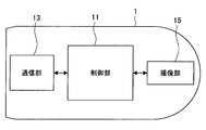
- FIG. 2 is a block diagram showing the configuration of the capsule 1 according to the first embodiment.
- the capsule 1 according to the present embodiment includes a control unit 11, a communication unit 13, and an imaging unit 15.
- the control unit 11 controls each configuration of the capsule 1. More specifically, the control unit 11 functions as an imaging control unit that controls the imaging unit 15 so as to continue imaging in the body cavity while moving in the body cavity.
- the control unit 11 performs through imaging control in which the captured image captured by the imaging unit 15 is not stored, and the captured image is sequentially transmitted from the communication unit 13 to the control device 3 in real time.
- an image captured by such through imaging control is referred to as a through image.
- the communication unit 13 is an interface for performing data communication with the control device 3. More specifically, the communication unit 13 according to the present embodiment continuously transmits the through image output from the imaging unit 15 to the control device 3.
- the imaging unit 15 is realized by an illumination unit such as a white LED, an imaging optical system including an imaging lens, and an imaging element (CMOS imager, CCD, etc.), and irradiates a body cavity with a white LED or the like to perform imaging.
- an illumination unit such as a white LED, an imaging optical system including an imaging lens, and an imaging element (CMOS imager, CCD, etc.), and irradiates a body cavity with a white LED or the like to perform imaging.
- the control device 3 includes a control unit 31, a communication unit 32, a display unit 33, an operation input unit 34, an image DB (database) 35, and a difference information DB 37.
- the control unit 31 has a function of controlling each component of the control device 3. More specifically, the control unit 31 according to the present embodiment may function as the comparison unit 311, the storage control unit 313, the difference image generation unit 314, and the display control unit 315.
- the comparison unit 311 compares the through image (captured image) in the body cavity that is transmitted from the capsule 1 as needed and the reference image extracted from the image DB 35, for example, compares the difference (or degree of coincidence) between the two images. As a result, it can be extracted.
- the reference image is a past image or a future (predicted) image of a predetermined part.
- a future (predicted) image is generated based on a predicted prediction image that is generated based on a prediction when a predetermined part that appears in a past image deteriorates, or a prediction that is generated when a predetermined part that appears in a past image is recovered (healed)
- the recovered predicted image may be used.
- the comparison unit 311 may determine a reference image to be extracted from the image data DB 35 in accordance with an instruction from the user, or may extract a preset reference image.
- the comparison unit 311 outputs the comparison result between the through image and the reference image to the storage control unit 313.
- the storage control unit 313 performs control so that a through image obtained by capturing the same part as the part shown in the reference image is stored in the image data DB 35 as a current image based on the comparison result by the comparison unit 311. Further, the storage control unit 313 may store the through image in the image data DB 35 and control to store the difference information included in the comparison result in the difference information DB 37.
- the storage control unit 313 may store a through image that substantially matches the reference image in the image data DB 35.
- the storage control unit 313 may perform control so that a through image having a locally large difference (locally low matching degree) is stored in the image data DB 35.
- the storage control unit 313 determines that the difference becomes smaller (the degree of coincidence increases) as the comparison range becomes larger, based on the comparison result when the comparison unit 311 compares the comparison range of the through image with enlargement / reduction. You may control to memorize
- the storage control unit 313 may perform control so as to store the through image when the marker attached in the vicinity of the predetermined portion that appears in the through image matches the marker that appears in the reference image.
- the storage control unit 313 can store, in the image data DB 35, a through image that captures the same part as the reference image among the through images transmitted from the capsule 1 in real time.
- the difference image generation part 314 produces
- the method for generating the difference image is not particularly limited, but an example of the difference image will be described later with reference to FIG. Further, the generated difference image may be displayed on the display unit 33 by the display control unit 315 described below, or may be stored in the difference information DB 37.
- Display control unit 315 controls the content (display screen) displayed on the display unit 33. More specifically, for example, the display control unit 315 may control to display the difference image generated by the difference image generation unit 314, the reference image, the current image, and the like on the display unit 33.
- the image data DB 35 is a storage unit that stores reference images (past images, deterioration prediction images, recovery prediction images, and the like) and through images (current images) according to control by the storage control unit 313.
- the difference information DB 37 is a storage unit that stores difference information indicating the difference between the reference image and the through image included in the comparison result by the comparison unit 311.
- the difference information DB 37 may store the difference image generated by the difference image generation unit 314.
- the communication unit 32 is an interface for connecting to an external device and transmitting / receiving data. More specifically, the communication unit 32 according to the present embodiment receives a through image from the capsule 1.
- the display unit 33 has a function of performing screen display such as an operation screen and an observation result screen under the control of the display control unit 315.
- the display unit 33 may be realized by an LCD (Liquid Crystal Display), an OLED (Organic Light-Emitting Diode), a CRT (Cathode Ray Tube), or the like.
- the operation input unit 34 has a function of detecting an operation by the user and outputting an input signal generated based on the detected operation input to the control unit 31.
- the operation input unit 34 may be realized by a mouse, a keyboard, a touch panel, or the like.
- FIG. 4 is a flowchart showing an operation process of the observation system according to the first embodiment.
- the capsule 1 performs through imaging while moving within the body cavity of the subject 4 (step S112), and sequentially transmits the through image to the control device 3 in real time (step S115).
- the comparison unit 311 of the control device 3 compares the through image transmitted from the capsule 1 with a reference image (for example, a past image) extracted from the image data DB 35 (step S115).
- a reference image for example, a past image
- the storage control unit 313 controls to store the through image as the current image in the image data DB 35 based on the comparison result by the comparison unit 311 (step S121). As described above, the storage control unit 313 performs control so as to store a through image that captures the same part as the part shown in the reference image.
- the difference image generation unit 314 generates a difference image obtained by imaging the difference between the reference image and the through image, and controls the display control unit 315 to display the difference image on the display unit 33 (step S124).
- FIG. 5 is a diagram illustrating an example of an observation result display screen (hereinafter referred to as a result screen) according to the present embodiment.
- the result screen 40 includes a part screen 41 showing each body part and an operation instruction display 42.
- the part screen 41 may be an image in which illustrations and names of the parts are associated with each other as shown in FIG.
- affected part icons 43a, 43b, and 43c are displayed at positions corresponding to the observed predetermined parts.
- an operation instruction such as “Please select a part to be observed from the affected area shown in the left figure” is displayed.
- FIG. 6 is a diagram showing an example of a screen displayed after selecting an observation site on the result screen 40 shown in FIG.
- a menu button related to the observation result of the part corresponding to the affected area icon 43c is displayed. Specifically, as shown in FIG. 6, a past image display button 44, a current image display button 46, a difference image display button 49, and a continuous difference image display button 51 are displayed.
- the display control unit 315 extracts a past image of a predetermined part corresponding to the affected part icon 43c from the image data DB 35 and displays it.
- the display control unit 315 may display the display button of each prediction image as a menu button.
- the display control unit 315 extracts a current image of a predetermined part corresponding to the affected area icon 43c from the image data DB 35 and displays it.
- the difference image display button 49 is selected, the display control unit 315 is generated by the difference image generation unit 314 based on the past image, current image, and comparison result (difference information) of a predetermined part corresponding to the affected area icon 43c. Display the difference image.
- An example of the difference image is shown in FIG.
- difference image 53 shown in FIG. 7 a portion (difference portion) different from the past image in the current image is displayed with a solid line so that a change in the affected area (difference between the past image and the current image) becomes clear, and a matching portion is a broken line Is displayed.
- the method of expressing the difference image is not limited to this.
- the difference portion may be displayed in a color different from that of the matching portion, or the luminance, transparency, and density of the difference portion and the matching portion may be different.
- the matching portion may be colorless (not displayed), and only the difference portion may be displayed with a color.
- the display control unit 315 continuously displays the difference image of the predetermined part continuously observed.
- a plurality of difference images may be displayed side by side according to time series, or a plurality of difference images may be sequentially displayed (moving image display) according to time series.
- the observation system according to the first embodiment described above includes the capsule 1 and the control device 3 as described with reference to FIGS. 1 and 4, and performs comparison and storage control on the control device 3 side.
- the observation system according to the present disclosure is not limited to the configuration according to the first embodiment.
- the capsule medical device may perform a comparison and storage control.
- a second embodiment in which the capsule medical device performs comparison and storage control in this way will be described in detail with reference to FIGS.
- FIG. 8 is a block diagram showing the configuration of the capsule medical device 2 according to the second embodiment.
- the capsule medical device 2 (hereinafter referred to as a capsule 2) according to the present embodiment includes a control unit 21, a storage unit 23, and an imaging unit 15. Since the imaging unit 15 has been described in the first embodiment, description thereof is omitted here.
- the control unit 21 controls each configuration of the capsule 2. More specifically, the control unit 21 functions as an imaging control unit 210 that controls the imaging unit 15 to image the inside of the body cavity, a comparison unit 213, and a storage control unit 215.
- the imaging control unit 210 controls to continuously capture through the body cavity while moving in the body cavity of the subject 4.
- the comparison unit 213 compares the through image (captured image) captured by the imaging unit 15 with the reference image stored in advance in the storage unit 23, and compares the comparison unit 311 according to the first embodiment described above. Similarly, for example, a difference between both images may be extracted as a comparison result.
- the comparison unit 213 may sequentially compare each reference image with a through image.
- the comparison unit 213 outputs a comparison result between the through image and the reference image to the storage control unit 313.
- the storage control unit 215 controls the storage unit 23 to store a through image obtained by capturing the same part as the part shown in the reference image based on the comparison result by the comparison unit 213. Further, the storage control unit 215 may control to store the difference information included in the comparison result in the storage unit 23 in association with the through image.
- Specific storage control by the storage control unit 215 is the same as that of the storage control unit 313 according to the first embodiment described above, and a description thereof will be omitted here.
- the storage unit 23 may be a removable memory card that is realized by a ROM (Read Only Memory), a RAM (Random Access Memory), or the like.
- the storage unit 23 according to the present embodiment is a storage unit that stores the above-described reference image (past image, deterioration prediction image, recovery prediction image, etc.) and a through image (current image) according to control by the storage control unit 215. .
- the storage unit 23 may store difference information indicating the difference between the reference image and the through image included in the comparison result by the comparison unit 213.
- FIG. 9 is a flowchart showing an operation process according to the second embodiment. As shown in FIG. 9, first, the imaging control unit 210 of the capsule 2 introduced into the body cavity controls the imaging unit 15 to perform through imaging inside the body cavity (step S136).
- the comparison unit 213 compares the through image (captured image) captured by the imaging unit 15 with a reference image (for example, a past image) extracted from the storage unit 23 (step S139).
- the storage control unit 215 controls to store the through image as the current image in the storage unit 23 based on the comparison result by the comparison unit 213 (step S142). As described above, the storage control unit 215 controls to store a through image that captures the same part as the part shown in the reference image.
- the operation processing of the observation system according to this embodiment has been described in detail above.
- the capsule 2 described above moves in the body cavity and is naturally discharged from the subject 4, and then is collected by a user such as the subject 4 or a medical staff, and the current image and difference information stored in the storage unit 23 are stored. It is taken out.
- the current image and difference information taken out from the capsule 2 are used when generating the above-described difference image, or when displaying the observation result display screen described in “2-3. Display example” above. Or
- a through image in the imaging range that matches the imaging range of the reference image among the through images captured in real time in the body cavity is captured (current image).
- the difference between the reference image and the current image is a changed part of the affected part, for example, by displaying a difference image obtained by imaging the difference, the user such as the subject 4 or the medical staff observes the change of the affected part. be able to.
- the user can monitor the progress of the affected area after the operation.
- a recovery prediction image in which recovery of the affected area is predicted a deterioration prediction image in which deterioration of the affected area is predicted, and a difference image between the current image and the current image are displayed. You can check if you are heading. Thereby, the user can continue the treatment according to the initial degree of healing of the affected part and the progress of the disease.
- the capsules 1 and 2 control the imaging range by the imaging unit 15 so that the reference image matches the imaging range (matches the position) based on the comparison result of the reference image and the through image. May be.
- the capsule 1 may receive a reference image from the control device 3 or have a reference image in advance, and compare the reference image and the through image.
- the control unit 31 of the capsule 1 may transmit a through image obtained by imaging the same part as the part shown in the reference image to the control device 3, or control difference information indicating a difference between the through image and the reference image. You may transmit to the apparatus 3. Thereby, compared with 1st Embodiment which transmits a through image to the control apparatus 3 continuously in real time, the amount of transmission data can be reduced.
- the image stored as the current image by the storage control unit is treated as a past image when the next current image of the same part is acquired.
- the observation system according to the present embodiment is smoothly displayed on the observation result display screen when the current image is closer to the deterioration prediction image than the recovery prediction image. You may warn that it has not recovered.
- the image data DB 35 and the difference information DB 37 according to the first embodiment are provided in the control device 3, but the present disclosure is not limited thereto, and the image data DB is provided on a network connected to the control device 3, for example. Or a difference information DB.
- the control unit 31 of the control device 3 (storage control device) has a difference between a current image obtained by imaging a predetermined part and a reference image equal to or greater than a predetermined threshold value.
- it may function as a notification unit for notifying a user such as a subject or a medical staff of a warning when an abnormal change is found.
- the notification unit can notify the user of an abnormal change (lesion site) by, for example, displaying a warning on the display unit 33.
- the control unit 21 of the capsule 2 (imaging control device), as a result of the comparison by the comparison unit 213, has a difference between a current image obtained by imaging a predetermined part and a reference image that is equal to or greater than a predetermined threshold. If an abnormal change is found, it may function as a notification unit for notifying a user (external) such as a subject or a medical staff.
- the notification unit can notify the user of an abnormal change (lesion site) by, for example, notifying an external device of a warning via a communication unit (not shown) included in the capsule 2.
- this technique can also take the following structures.
- An imaging control unit that controls the imaging unit to image a predetermined part in the body cavity;
- a comparison unit that compares a captured image captured by the imaging unit with a reference image;
- a storage control unit that controls to store the captured image according to a comparison result by the comparison unit;
- An imaging control apparatus comprising: (2) The imaging control device according to (1), wherein the imaging control device is a capsule medical device.
- the storage control unit controls to store the captured image in which the difference becomes smaller as the comparison range is larger, based on the comparison result when the comparison unit expands or reduces the comparison range of the captured image.
- the imaging control device according to any one of (1) to (3).
- the storage control unit performs control so as to store the captured image when a marker attached in the vicinity of a predetermined portion that appears in the captured image matches a marker that appears in the reference image, (1) to (4)
- the imaging control device according to any one of the above.
- (6) The imaging control according to any one of (1) to (5), wherein the reference image is a past image of the predetermined part or a predicted image generated by predicting a change in the predetermined part. apparatus.
- the prediction image is based on a prediction when the predetermined part is recovered, based on a recovery prediction image generated by processing a captured image of the predetermined part, or a prediction when the predetermined part is deteriorated
- the imaging control device according to (6), wherein the imaging control device is a deterioration prediction image generated by processing a captured image of the predetermined part.
- the imaging control device includes: The imaging control according to any one of (1) to (7), further comprising: a notification unit that issues a warning notification to the outside when a difference between the captured image and the reference image is equal to or greater than a predetermined threshold as a result of comparison by the comparison unit. apparatus.
- An imaging control unit that controls an imaging unit that images a predetermined part in a body cavity; A transmission unit that transmits a captured image captured by the imaging unit;
- An imaging control device comprising: A receiving unit that receives the captured image from the imaging control device; A comparison unit that compares a captured image received by the reception unit with a reference image; A storage control unit that controls to store the captured image in a storage unit according to a comparison result by the comparison unit; A storage control device comprising: A storage system.
- the storage controller is A display control unit for controlling to display a comparison result by the comparison unit; The storage system according to (9) above.
- the comparison unit outputs a difference between the captured image and the reference image as the comparison result,
- the storage system according to (10), wherein the display control unit controls to display a difference image obtained by imaging the difference.
- the storage controller is The comparison unit according to any one of (9) to (11), further including a notification unit that issues a warning notification when a difference between the captured image and the reference image is equal to or greater than a predetermined threshold as a result of the comparison by the comparison unit.
- An imaging control unit that controls the imaging unit to image a predetermined part in the body cavity;
- a comparison unit that compares a captured image captured by the imaging unit with a reference image;
- a storage control unit that controls to store the captured image according to a comparison result by the comparison unit;
Landscapes
- Engineering & Computer Science (AREA)
- Health & Medical Sciences (AREA)
- Life Sciences & Earth Sciences (AREA)
- Physics & Mathematics (AREA)
- Surgery (AREA)
- Theoretical Computer Science (AREA)
- General Health & Medical Sciences (AREA)
- Medical Informatics (AREA)
- Nuclear Medicine, Radiotherapy & Molecular Imaging (AREA)
- Radiology & Medical Imaging (AREA)
- General Physics & Mathematics (AREA)
- Computer Vision & Pattern Recognition (AREA)
- Biomedical Technology (AREA)
- Heart & Thoracic Surgery (AREA)
- Molecular Biology (AREA)
- Animal Behavior & Ethology (AREA)
- Public Health (AREA)
- Veterinary Medicine (AREA)
- Pathology (AREA)
- Optics & Photonics (AREA)
- Biophysics (AREA)
- Multimedia (AREA)
- Data Mining & Analysis (AREA)
- Artificial Intelligence (AREA)
- Evolutionary Computation (AREA)
- Software Systems (AREA)
- Quality & Reliability (AREA)
- General Engineering & Computer Science (AREA)
- Bioinformatics & Cheminformatics (AREA)
- Bioinformatics & Computational Biology (AREA)
- Databases & Information Systems (AREA)
- Evolutionary Biology (AREA)
- Signal Processing (AREA)
- Computing Systems (AREA)
- Human Computer Interaction (AREA)
- Computer Networks & Wireless Communication (AREA)
- Endoscopes (AREA)
- Measurement Of The Respiration, Hearing Ability, Form, And Blood Characteristics Of Living Organisms (AREA)
Abstract
Priority Applications (4)
| Application Number | Priority Date | Filing Date | Title |
|---|---|---|---|
| US14/409,556 US9406123B2 (en) | 2012-06-26 | 2013-04-05 | Imaging control apparatus, storage system, and storage medium |
| CN201380032676.2A CN104379049A (zh) | 2012-06-26 | 2013-04-05 | 成像控制设备、存储系统及存储介质 |
| JP2014522456A JP6217632B2 (ja) | 2012-06-26 | 2013-04-05 | 撮像制御装置、記憶システムおよび記憶媒体 |
| US15/193,606 US9911186B2 (en) | 2012-06-26 | 2016-06-27 | Imaging control apparatus, storage system, and storage medium |
Applications Claiming Priority (2)
| Application Number | Priority Date | Filing Date | Title |
|---|---|---|---|
| JP2012142619 | 2012-06-26 | ||
| JP2012-142619 | 2012-06-26 |
Related Child Applications (2)
| Application Number | Title | Priority Date | Filing Date |
|---|---|---|---|
| US14/409,556 A-371-Of-International US9406123B2 (en) | 2012-06-26 | 2013-04-05 | Imaging control apparatus, storage system, and storage medium |
| US15/193,606 Continuation US9911186B2 (en) | 2012-06-26 | 2016-06-27 | Imaging control apparatus, storage system, and storage medium |
Publications (1)
| Publication Number | Publication Date |
|---|---|
| WO2014002565A1 true WO2014002565A1 (fr) | 2014-01-03 |
Family
ID=49782743
Family Applications (1)
| Application Number | Title | Priority Date | Filing Date |
|---|---|---|---|
| PCT/JP2013/060504 Ceased WO2014002565A1 (fr) | 2012-06-26 | 2013-04-05 | Dispositif de commande d'imagerie, système d'enregistrement et support d'enregistrement |
Country Status (4)
| Country | Link |
|---|---|
| US (2) | US9406123B2 (fr) |
| JP (1) | JP6217632B2 (fr) |
| CN (1) | CN104379049A (fr) |
| WO (1) | WO2014002565A1 (fr) |
Cited By (6)
| Publication number | Priority date | Publication date | Assignee | Title |
|---|---|---|---|---|
| WO2018105351A1 (fr) * | 2016-12-06 | 2018-06-14 | オリンパス株式会社 | Dispositif d'endoscope, système d'endoscope et procédé d'aide à l'examen |
| WO2018159347A1 (fr) * | 2017-02-28 | 2018-09-07 | 富士フイルム株式会社 | Dispositif de processeur, système d'endoscope, et procédé de fonctionnement d'un dispositif de processeur |
| CN110505383A (zh) * | 2019-08-29 | 2019-11-26 | 重庆金山医疗技术研究院有限公司 | 一种图像获取方法、图像获取装置及内窥镜系统 |
| JP2020077965A (ja) * | 2018-11-07 | 2020-05-21 | 富士通株式会社 | 画像処理プログラム、画像処理装置、画像処理システム、及び画像処理方法 |
| CN114073512A (zh) * | 2020-08-21 | 2022-02-22 | 富士胶片医疗健康株式会社 | 磁共振成像装置以及其控制方法和程序 |
| WO2024185099A1 (fr) * | 2023-03-08 | 2024-09-12 | 日本電気株式会社 | Dispositif d'assistance à l'endoscopie, procédé d'assistance à l'endoscopie, et support d'enregistrement |
Families Citing this family (7)
| Publication number | Priority date | Publication date | Assignee | Title |
|---|---|---|---|---|
| WO2014002565A1 (fr) * | 2012-06-26 | 2014-01-03 | ソニー株式会社 | Dispositif de commande d'imagerie, système d'enregistrement et support d'enregistrement |
| JP6318739B2 (ja) * | 2014-03-17 | 2018-05-09 | コニカミノルタ株式会社 | 画像処理装置、およびプログラム |
| JP6080268B2 (ja) * | 2014-09-29 | 2017-02-15 | 富士フイルム株式会社 | 医用画像保存処理装置および方法並びにプログラム |
| PL3215219T3 (pl) * | 2014-11-06 | 2024-05-13 | Koninklijke Philips N.V. | System do zabiegów na skórze |
| WO2018159363A1 (fr) * | 2017-03-01 | 2018-09-07 | 富士フイルム株式会社 | Système d'endoscope et son procédé de fonctionnement |
| JP6656207B2 (ja) * | 2017-05-31 | 2020-03-04 | キヤノン株式会社 | 情報処理装置、その制御方法、及びプログラム |
| CN110693441A (zh) * | 2019-08-28 | 2020-01-17 | 张建国 | 一种内窥镜成像方法及装置 |
Citations (10)
| Publication number | Priority date | Publication date | Assignee | Title |
|---|---|---|---|---|
| JP2003038425A (ja) * | 2001-07-30 | 2003-02-12 | Olympus Optical Co Ltd | カプセル内視鏡 |
| JP2005102851A (ja) * | 2003-09-29 | 2005-04-21 | Olympus Corp | 投薬用カプセル及びカプセル型医療装置、カプセル型医療装置システム並びに制御方法 |
| JP2005103130A (ja) * | 2003-10-01 | 2005-04-21 | Olympus Corp | カプセル投薬システム |
| JP2005192879A (ja) * | 2004-01-08 | 2005-07-21 | Olympus Corp | カプセル型医療装置 |
| JP2005334331A (ja) * | 2004-05-27 | 2005-12-08 | Olympus Corp | カプセル投薬システム |
| JP2008194334A (ja) * | 2007-02-15 | 2008-08-28 | Fujifilm Corp | 内視鏡画像表示方法および装置ならびにプログラム |
| JP2010046216A (ja) * | 2008-08-20 | 2010-03-04 | Fujifilm Corp | 光断層画像取得装置及び光断層画像取得方法 |
| JP2010220794A (ja) * | 2009-03-24 | 2010-10-07 | Fujifilm Corp | 内視鏡画像回転装置および方法並びにプログラム |
| JP2012010862A (ja) * | 2010-06-30 | 2012-01-19 | Olympus Corp | 蛍光観察装置 |
| JP4861540B2 (ja) * | 2010-05-10 | 2012-01-25 | オリンパスメディカルシステムズ株式会社 | 医療装置 |
Family Cites Families (9)
| Publication number | Priority date | Publication date | Assignee | Title |
|---|---|---|---|---|
| US6951536B2 (en) * | 2001-07-30 | 2005-10-04 | Olympus Corporation | Capsule-type medical device and medical system |
| US8021356B2 (en) | 2003-09-29 | 2011-09-20 | Olympus Corporation | Capsule medication administration system, medication administration method using capsule medication administration system, control method for capsule medication administration system |
| US8306592B2 (en) | 2003-12-19 | 2012-11-06 | Olympus Corporation | Capsule medical device |
| JP4523293B2 (ja) | 2004-01-21 | 2010-08-11 | オリンパス株式会社 | 生体の経過観察用カプセル内視鏡、カプセル内視鏡導入装置及びカプセル内視鏡導入システム |
| US7324661B2 (en) * | 2004-04-30 | 2008-01-29 | Colgate-Palmolive Company | Computer-implemented system and method for automated and highly accurate plaque analysis, reporting, and visualization |
| JP4734051B2 (ja) | 2005-07-08 | 2011-07-27 | オリンパス株式会社 | カプセル型医療装置用留置装置及びカプセル内視鏡用生体内留置装置 |
| JP5405445B2 (ja) * | 2010-12-17 | 2014-02-05 | 富士フイルム株式会社 | 内視鏡装置 |
| CN102397052B (zh) * | 2011-11-30 | 2014-01-15 | 西交利物浦大学 | 基于图像识别技术的可调节拍摄速率的无线胶囊内窥镜系统及方法 |
| WO2014002565A1 (fr) * | 2012-06-26 | 2014-01-03 | ソニー株式会社 | Dispositif de commande d'imagerie, système d'enregistrement et support d'enregistrement |
-
2013
- 2013-04-05 WO PCT/JP2013/060504 patent/WO2014002565A1/fr not_active Ceased
- 2013-04-05 JP JP2014522456A patent/JP6217632B2/ja active Active
- 2013-04-05 CN CN201380032676.2A patent/CN104379049A/zh active Pending
- 2013-04-05 US US14/409,556 patent/US9406123B2/en active Active
-
2016
- 2016-06-27 US US15/193,606 patent/US9911186B2/en active Active
Patent Citations (10)
| Publication number | Priority date | Publication date | Assignee | Title |
|---|---|---|---|---|
| JP2003038425A (ja) * | 2001-07-30 | 2003-02-12 | Olympus Optical Co Ltd | カプセル内視鏡 |
| JP2005102851A (ja) * | 2003-09-29 | 2005-04-21 | Olympus Corp | 投薬用カプセル及びカプセル型医療装置、カプセル型医療装置システム並びに制御方法 |
| JP2005103130A (ja) * | 2003-10-01 | 2005-04-21 | Olympus Corp | カプセル投薬システム |
| JP2005192879A (ja) * | 2004-01-08 | 2005-07-21 | Olympus Corp | カプセル型医療装置 |
| JP2005334331A (ja) * | 2004-05-27 | 2005-12-08 | Olympus Corp | カプセル投薬システム |
| JP2008194334A (ja) * | 2007-02-15 | 2008-08-28 | Fujifilm Corp | 内視鏡画像表示方法および装置ならびにプログラム |
| JP2010046216A (ja) * | 2008-08-20 | 2010-03-04 | Fujifilm Corp | 光断層画像取得装置及び光断層画像取得方法 |
| JP2010220794A (ja) * | 2009-03-24 | 2010-10-07 | Fujifilm Corp | 内視鏡画像回転装置および方法並びにプログラム |
| JP4861540B2 (ja) * | 2010-05-10 | 2012-01-25 | オリンパスメディカルシステムズ株式会社 | 医療装置 |
| JP2012010862A (ja) * | 2010-06-30 | 2012-01-19 | Olympus Corp | 蛍光観察装置 |
Cited By (9)
| Publication number | Priority date | Publication date | Assignee | Title |
|---|---|---|---|---|
| WO2018105351A1 (fr) * | 2016-12-06 | 2018-06-14 | オリンパス株式会社 | Dispositif d'endoscope, système d'endoscope et procédé d'aide à l'examen |
| WO2018159347A1 (fr) * | 2017-02-28 | 2018-09-07 | 富士フイルム株式会社 | Dispositif de processeur, système d'endoscope, et procédé de fonctionnement d'un dispositif de processeur |
| JPWO2018159347A1 (ja) * | 2017-02-28 | 2019-12-19 | 富士フイルム株式会社 | プロセッサ装置、内視鏡システム及びプロセッサ装置の作動方法 |
| JP2020077965A (ja) * | 2018-11-07 | 2020-05-21 | 富士通株式会社 | 画像処理プログラム、画像処理装置、画像処理システム、及び画像処理方法 |
| JP7142543B2 (ja) | 2018-11-07 | 2022-09-27 | 富士通株式会社 | 画像処理プログラム、画像処理装置、画像処理システム、及び画像処理方法 |
| CN110505383A (zh) * | 2019-08-29 | 2019-11-26 | 重庆金山医疗技术研究院有限公司 | 一种图像获取方法、图像获取装置及内窥镜系统 |
| CN114073512A (zh) * | 2020-08-21 | 2022-02-22 | 富士胶片医疗健康株式会社 | 磁共振成像装置以及其控制方法和程序 |
| US12484782B2 (en) | 2020-08-21 | 2025-12-02 | Fujifilm Corporation | Magnetic resonance imaging apparatus, and control method and control program thereof |
| WO2024185099A1 (fr) * | 2023-03-08 | 2024-09-12 | 日本電気株式会社 | Dispositif d'assistance à l'endoscopie, procédé d'assistance à l'endoscopie, et support d'enregistrement |
Also Published As
| Publication number | Publication date |
|---|---|
| US9911186B2 (en) | 2018-03-06 |
| US20160307317A1 (en) | 2016-10-20 |
| US9406123B2 (en) | 2016-08-02 |
| CN104379049A (zh) | 2015-02-25 |
| JPWO2014002565A1 (ja) | 2016-05-30 |
| JP6217632B2 (ja) | 2017-10-25 |
| US20150254836A1 (en) | 2015-09-10 |
Similar Documents
| Publication | Publication Date | Title |
|---|---|---|
| JP6217632B2 (ja) | 撮像制御装置、記憶システムおよび記憶媒体 | |
| US11123150B2 (en) | Information processing apparatus, assistance system, and information processing method | |
| CN101637379B (zh) | 内窥镜系统以及图像显示方法 | |
| EP3994702B1 (fr) | Système de support chirurgical, procédé de support chirurgical, appareil de traitement d'informations et programme de traitement d'informations | |
| JP6284439B2 (ja) | 医療情報処理システム | |
| JP2010035756A (ja) | 診断支援装置及び診断支援方法 | |
| JP6368885B1 (ja) | 内視鏡システム、端末装置、サーバ、送信方法およびプログラム | |
| CN105283114B (zh) | 胶囊型内窥镜系统 | |
| JP2009039449A (ja) | 画像処理装置 | |
| CN102753078B (zh) | 图像显示装置以及胶囊型内窥镜系统 | |
| JP2010082241A (ja) | 画像表示装置、画像表示方法、および画像表示プログラム | |
| US8368746B2 (en) | Apparatus and method for processing image information captured over time at plurality of positions in subject body | |
| US11114129B2 (en) | Information processing apparatus and information processing method | |
| JP5593008B1 (ja) | 画像処理装置及び画像処理方法 | |
| JP3984230B2 (ja) | 画像情報の表示処理装置、その表示処理方法及び表示処理プログラム | |
| JP4139319B2 (ja) | カプセル型内視鏡撮像画像ファイリング装置 | |
| CN101312680B (zh) | 图像显示系统 | |
| JP5684300B2 (ja) | 画像表示装置、画像表示方法、および画像表示プログラム | |
| JP4472602B2 (ja) | 画像表示装置 | |
| JP2012249956A (ja) | カプセル内視鏡画像処理装置及びカプセル内視鏡システム | |
| JP2014003994A (ja) | 医療装置、システムおよびプログラム |
Legal Events
| Date | Code | Title | Description |
|---|---|---|---|
| 121 | Ep: the epo has been informed by wipo that ep was designated in this application |
Ref document number: 13810566 Country of ref document: EP Kind code of ref document: A1 |
|
| ENP | Entry into the national phase |
Ref document number: 2014522456 Country of ref document: JP Kind code of ref document: A |
|
| WWE | Wipo information: entry into national phase |
Ref document number: 14409556 Country of ref document: US |
|
| NENP | Non-entry into the national phase |
Ref country code: DE |
|
| 122 | Ep: pct application non-entry in european phase |
Ref document number: 13810566 Country of ref document: EP Kind code of ref document: A1 |