WO2014002811A1 - 画像処理装置、画像処理方法および画像処理プログラム - Google Patents
画像処理装置、画像処理方法および画像処理プログラム Download PDFInfo
- Publication number
- WO2014002811A1 WO2014002811A1 PCT/JP2013/066580 JP2013066580W WO2014002811A1 WO 2014002811 A1 WO2014002811 A1 WO 2014002811A1 JP 2013066580 W JP2013066580 W JP 2013066580W WO 2014002811 A1 WO2014002811 A1 WO 2014002811A1
- Authority
- WO
- WIPO (PCT)
- Prior art keywords
- color component
- image processing
- component
- correlation
- color
- Prior art date
- Legal status (The legal status is an assumption and is not a legal conclusion. Google has not performed a legal analysis and makes no representation as to the accuracy of the status listed.)
- Ceased
Links
Images


Classifications
-
- G—PHYSICS
- G06—COMPUTING OR CALCULATING; COUNTING
- G06T—IMAGE DATA PROCESSING OR GENERATION, IN GENERAL
- G06T5/00—Image enhancement or restoration
- G06T5/73—Deblurring; Sharpening
-
- G—PHYSICS
- G06—COMPUTING OR CALCULATING; COUNTING
- G06T—IMAGE DATA PROCESSING OR GENERATION, IN GENERAL
- G06T5/00—Image enhancement or restoration
- G06T5/80—Geometric correction
-
- G—PHYSICS
- G06—COMPUTING OR CALCULATING; COUNTING
- G06T—IMAGE DATA PROCESSING OR GENERATION, IN GENERAL
- G06T5/00—Image enhancement or restoration
- G06T5/50—Image enhancement or restoration using two or more images, e.g. averaging or subtraction
-
- H—ELECTRICITY
- H04—ELECTRIC COMMUNICATION TECHNIQUE
- H04N—PICTORIAL COMMUNICATION, e.g. TELEVISION
- H04N25/00—Circuitry of solid-state image sensors [SSIS]; Control thereof
- H04N25/60—Noise processing, e.g. detecting, correcting, reducing or removing noise
- H04N25/61—Noise processing, e.g. detecting, correcting, reducing or removing noise the noise originating only from the lens unit, e.g. flare, shading, vignetting or "cos4"
- H04N25/615—Noise processing, e.g. detecting, correcting, reducing or removing noise the noise originating only from the lens unit, e.g. flare, shading, vignetting or "cos4" involving a transfer function modelling the optical system, e.g. optical transfer function [OTF], phase transfer function [PhTF] or modulation transfer function [MTF]
- H04N25/6153—Noise processing, e.g. detecting, correcting, reducing or removing noise the noise originating only from the lens unit, e.g. flare, shading, vignetting or "cos4" involving a transfer function modelling the optical system, e.g. optical transfer function [OTF], phase transfer function [PhTF] or modulation transfer function [MTF] for colour signals
-
- H—ELECTRICITY
- H04—ELECTRIC COMMUNICATION TECHNIQUE
- H04N—PICTORIAL COMMUNICATION, e.g. TELEVISION
- H04N9/00—Details of colour television systems
- H04N9/64—Circuits for processing colour signals
- H04N9/646—Circuits for processing colour signals for image enhancement, e.g. vertical detail restoration, cross-colour elimination, contour correction, chrominance trapping filters
-
- G—PHYSICS
- G06—COMPUTING OR CALCULATING; COUNTING
- G06T—IMAGE DATA PROCESSING OR GENERATION, IN GENERAL
- G06T2207/00—Indexing scheme for image analysis or image enhancement
- G06T2207/10—Image acquisition modality
- G06T2207/10004—Still image; Photographic image
-
- G—PHYSICS
- G06—COMPUTING OR CALCULATING; COUNTING
- G06T—IMAGE DATA PROCESSING OR GENERATION, IN GENERAL
- G06T2207/00—Indexing scheme for image analysis or image enhancement
- G06T2207/10—Image acquisition modality
- G06T2207/10024—Color image
-
- G—PHYSICS
- G06—COMPUTING OR CALCULATING; COUNTING
- G06T—IMAGE DATA PROCESSING OR GENERATION, IN GENERAL
- G06T2207/00—Indexing scheme for image analysis or image enhancement
- G06T2207/20—Special algorithmic details
- G06T2207/20172—Image enhancement details
- G06T2207/20201—Motion blur correction
Definitions
- the present invention relates to an image processing apparatus, an image processing method, and an image processing program for correcting image blur.
- Patent Document 1 discloses a method for correcting chromatic aberration of an image captured through an optical system. More specifically, in the related art, smoothing or thru of one color component of at least two color components of the first image having different MTF characteristics between at least two color components on the imaging surface. A plurality of processes for correcting the MTF by performing a sharpening process are performed, and the color responses between them are compared. Based on the comparison result of the color response, one MTF correction process is determined from among a plurality of MTF processes, and the MTF characteristic of one color component of at least two color components is determined as the MTF of another color component. Match the characteristics.
- an object of the present invention is to provide an image processing apparatus, an image processing method, and an image processing program that can more appropriately correct blur due to chromatic aberration. is there.
- An image processing apparatus provides a first acquisition unit that acquires an input image expressed by a plurality of color components including at least a first color component and a second color component, and a first region of interest in the input image.
- a correlation degree calculation unit that calculates a density direction correlation indicating whether the color components of the second color component and the second color component are in the same direction or the opposite direction, and a high frequency component of the first color component for the attention area
- the correction unit applies the second color component to the second color component when the gray level direction correlation degree indicates a positive correlation in which the first color component and the second color component are in the same direction.
- the high-frequency component of the first color component is added and the shade direction correlation degree for the attention area indicates a negative correlation in which the shade direction of the first color component and the second color component is opposite,
- the second color component is not corrected by the high frequency component of the first color component.
- the correction unit determines a positive correlation when the gray level correlation degree for the attention area exceeds a predetermined value ⁇ ( ⁇ > 0), and the gray level correlation degree for the attention area is a predetermined value ⁇ ( ⁇ ⁇ ⁇
- the first color is determined to be negative when it falls below 0), and is reduced compared to the case of positive correlation when the degree of contrast in the light and dark direction in the region of interest is in the range from the predetermined value ⁇ to the predetermined value ⁇ .
- the high frequency component of the component is added to the second color component.
- the correction unit applies the second color component to the second color component when the gray level direction correlation degree indicates a positive correlation in which the first color component and the second color component are in the same direction.
- the high-frequency component of the first color component is added and the shade direction correlation degree for the attention area indicates a negative correlation in which the shade direction of the first color component and the second color component is opposite,
- the high frequency component of the first color component reduced as compared with the case of correlation is added to the second color component.
- the correction unit applies the second color component to the second color component when the gray level direction correlation degree indicates a positive correlation in which the first color component and the second color component are in the same direction.
- the high-frequency component of the first color component is added and the shade direction correlation degree for the attention area indicates a negative correlation in which the shade direction of the first color component and the second color component is opposite, The high frequency component of the first color component is subtracted from the two color components.
- the correction unit determines whether or not the high frequency component is included in the attention area. If the high attention frequency component is not included in the attention area, the correction area is determined by a method according to the grayscale direction correlation degree. If the high frequency component is included in the attention area while the second color component is corrected for the second area, the second color for the attention area is determined in a predetermined method without depending on the shade direction correlation degree. Correct the component.
- the correction unit corrects a degraded frequency band in the MTF characteristics of the second color component as compared with the MTF characteristics of the first color component.
- the correlation degree calculation unit calculates the light and dark direction correlation degree based on the high frequency components included in the first color component and the second color component.
- the correlation degree calculation unit calculates the grayscale direction correlation degree using a correlation value obtained by pattern matching the high frequency components included in the first color component and the second color component.
- the correlation degree calculation unit calculates the shade direction correlation degree by multiplying the correlation value by the magnitude of the shade change of the second color component.
- An image processing method includes a step of acquiring an input image expressed by a plurality of color components including at least a first color component and a second color component, and a first region for a region of interest in the input image. Calculating a light / dark correlation degree indicating whether the light and dark directions of the second color component and the second color component are the same direction or the opposite direction, and calculating a high frequency component of the first color component for the region of interest. And a step of correcting the second color component for the region of interest by using the high frequency component of the first color component by a method according to the grayscale direction correlation degree.
- an image processing program for causing a computer to execute image processing.
- the image processing program acquires, in a computer, an input image expressed by a plurality of color components including at least first and second color components, and the first color component and the second color for a region of interest in the input image.
- a step of calculating a shade direction correlation indicating whether the shade direction of the color components is the same direction or a reverse direction, a step of calculating a high frequency component of the first color component for the region of interest, and a shade direction correlation And a step of correcting the second color component for the region of interest using the high-frequency component of the first color component by a method according to the degree.
- FIG. 1 is a block diagram showing a basic configuration of an image processing apparatus according to an embodiment of the present invention. It is a block diagram which shows the structure of the digital camera which actualized the image processing apparatus shown in FIG. It is a block diagram which shows the structure of the personal computer which actualized the image processing apparatus shown in FIG. It is a figure for demonstrating the chromatic aberration made into the correction object by the image processing apparatus and image processing method according to embodiment of this invention. It is a flowchart which shows the procedure of the image processing method relevant to this invention. It is a figure which shows an example of the input image used as the process target of the image processing method relevant to this invention. It is a figure for demonstrating the extraction process of the high frequency component of the image processing method relevant to this invention.
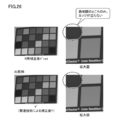
- FIG. 26 is a diagram for explaining the effect of correction by the input image correction processing shown in FIG. 25.
- FIG. 36 is a diagram for explaining the effect of correction by the input image correction processing shown in FIG. 35. It is a figure which shows an example of the correction result by the image processing method according to Embodiment 2 of this invention. It is a figure for demonstrating the outline
- the image processing apparatus typically includes a high-frequency component of a color (for example, G) having the best MTF characteristics when the input image includes blur due to axial chromatic aberration of the optical system. This is suitable for image correction processing in which correction is performed using high-frequency components of the colors (for example, R).
- the image processing apparatus calculates a gray-scale correlation degree between colors for the same region with respect to an input image expressed by a plurality of color components, and the calculated gray-scale correlation degree
- the correction method using the high frequency component is optimized according to the above.
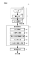
- FIG. 1 is a block diagram showing a basic configuration of an image processing apparatus 1 according to the embodiment of the present invention.
- the image processing apparatus 1 includes an imaging unit 2, an image processing unit 3, and an image output unit 4.
- the image capturing unit 2 captures an image of a subject to acquire an image (hereinafter also referred to as “input image”), and the image processing unit 3 performs an operation on the acquired input image.
- the image output unit 4 outputs the corrected input image (hereinafter also simply referred to as “corrected image”) to a display device or the like.
- the imaging unit 2 captures an object (subject) and generates an input image. More specifically, the imaging unit 2 includes a camera 22 and an A / D (Analog to Digital) conversion unit 24 connected to the camera 22. The A / D converter 24 outputs an input image indicating the subject imaged by the camera 22.
- a / D Analog to Digital
- the camera 22 includes a lens 22a that is an optical system for imaging a subject, and an image sensor 22b that is a device that converts light collected by the lens 22a into an electrical signal.
- the A / D converter 24 converts a video signal (analog electrical signal) indicating a subject output from the image sensor 22b into a digital signal and outputs the digital signal.
- the imaging unit 2 may further include a control processing circuit for controlling each part.
- the image processing unit 3 corrects the blur included in the input image by performing the image processing method according to the present embodiment on the input image acquired by the imaging unit 2. More specifically, the image processing unit 3 includes an LPF (Low Pass Filter) processing unit 30, a color space conversion unit 32, a light / dark direction correlation calculation unit 34, an edge correction unit 36, and an RGB correction. And an image generation unit 38.
- LPF Low Pass Filter
- the LPF processing unit 30 extracts a low frequency component from the input image to be processed.
- the color space conversion unit 32 converts the color space of the input image to be processed. Specifically, the color space conversion unit 32 converts an input image in the RGB color space into an image in the YCrCb color space.
- the light / dark direction correlation calculation unit 34 calculates the light / dark direction correlation degree for the input image to be processed. The details of the light / dark direction correlation will be described later.
- the edge correction unit 36 performs edge correction for correcting blur of the input image.
- the RGB correction image generation unit 38 converts the input image after the edge correction again into an image in the RGB color space and outputs it.
- the image output unit 4 outputs the corrected image generated by the image processing unit 3 to a display device or the like.
- the image processing apparatus 1 shown in FIG. 1 can be configured independently, but is generally embodied as a digital camera or a personal computer described below for general purposes. Therefore, an implementation example of the image processing apparatus 1 according to the present embodiment will be described.
- FIG. 2 is a block diagram showing a configuration of a digital camera 100 that embodies the image processing apparatus 1 shown in FIG. 2, components corresponding to the respective blocks constituting the image processing apparatus 1 shown in FIG. 1 are denoted by the same reference numerals as those in FIG. 1.
- a digital camera 100 includes a CPU (Central Processing Unit) 102, a digital processing circuit 104, an image display unit 108, a card interface (I / F) 110, a storage unit 112, and a zoom mechanism. 114 and the optical system 120.
- CPU Central Processing Unit
- the CPU 102 controls the entire digital camera 100 by executing a program stored in advance.
- the digital processing circuit 104 executes various digital processes including image processing according to the present embodiment.
- the digital processing circuit 104 is typically a DSP (Digital Signal Processor), an ASIC (Application Specific Integrated Circuit), an LSI (Large Scale Integration), an FPGA (Field-Programmable), or the like.
- the digital processing circuit 104 includes an image processing circuit 106 for realizing the functions provided by the image processing unit 3 shown in FIG.
- the image display unit 108 includes an input image provided by the optical system 120, an output image generated by the digital processing circuit 104 (image processing circuit 106), various setting information related to the digital camera 100, and a control GUI (Graphical User). Interface) screen or the like is displayed.
- GUI Graphic User
- the card interface (I / F) 110 is an interface for writing image data generated by the image processing circuit 106 to the storage unit 112 or reading image data or the like from the storage unit 112.
- the storage unit 112 is a storage device that stores image data generated by the image processing circuit 106 and various information (setting values such as control parameters and operation modes of the digital camera 100).
- the storage unit 112 includes a flash memory, an optical disk, a magnetic disk, and the like, and stores data in a nonvolatile manner.
- the zoom mechanism 114 is a mechanism that changes the imaging magnification of the optical system 120 in accordance with a user operation or the like.
- the zoom mechanism 114 typically includes a servo motor or the like, and changes the focal length by driving a lens group constituting the optical system 120.
- the optical system 120 generates an input image by imaging a subject.
- a digital camera 100 shown in FIG. 2 is obtained by mounting the entire image processing apparatus 1 according to the present embodiment as a single apparatus. That is, the user can visually recognize the subject in a three-dimensional manner on the image display unit 108 by imaging the subject using the digital camera 100.
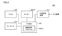
- FIG. 3 is a block diagram showing a configuration of a personal computer 200 that embodies the image processing apparatus 1 shown in FIG.
- the imaging unit 2 for acquiring an input image is not mounted, and an input image acquired by an arbitrary imaging unit 2 is input from the outside. Even such a configuration can be included in the image processing apparatus 1 according to the embodiment of the present invention.
- components corresponding to blocks constituting the image processing apparatus 1 shown in FIG. 1 are denoted by the same reference numerals as those in FIG.
- the personal computer 200 includes a personal computer main body 202, a monitor 206, a mouse 208, a keyboard 210, and an external storage device 212.
- the personal computer main body 202 is typically a general-purpose computer according to a general-purpose architecture, and includes a CPU, a RAM (Random Access Memory), a ROM (Read Only Memory), and the like as basic components.
- the personal computer main body 202 can execute an image processing program 204 for realizing a function provided by the image processing unit 3 shown in FIG.
- Such an image processing program 204 is stored and distributed in a storage medium such as a CD-ROM (Compact Disk-Read Only Memory), or distributed from a server device via a network.
- the image processing program 204 is stored in a storage area such as a hard disk of the personal computer main body 202.
- Such an image processing program 204 implements processing by calling necessary modules among program modules provided as part of an operating system (OS) executed by the personal computer main body 202 at a predetermined timing and order. It may be configured as follows. In this case, the image processing program 204 itself does not include a module provided by the OS, and image processing is realized in cooperation with the OS. Further, the image processing program 204 may be provided by being incorporated in a part of some program instead of a single program. Even in such a case, the image processing program 204 itself does not include a module that is commonly used in the program, and image processing is realized in cooperation with the program. Even such an image processing program 204 that does not include some modules does not depart from the spirit of the image processing apparatus 1 according to the present embodiment.
- OS operating system
- image processing program 204 may be realized by dedicated hardware.
- the monitor 206 displays a GUI screen provided by an operating system (OS), an image generated by the image processing program 204, and the like.
- OS operating system
- the mouse 208 and the keyboard 210 each accept a user operation and output the contents of the accepted user operation to the personal computer main body 202.
- the external storage device 212 stores an input image acquired by some method, and outputs this input image to the personal computer main body 202.
- a device that stores data in a nonvolatile manner such as a flash memory, an optical disk, or a magnetic disk is used.
- a personal computer 200 shown in FIG. 3 is obtained by mounting a part of the image processing apparatus 1 according to the present embodiment as a single apparatus.
- chromatic aberration axial chromatic aberration
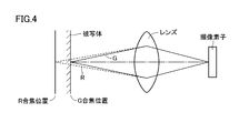
- FIG. 4 is a diagram for explaining chromatic aberration to be corrected by the image processing apparatus and the image processing method according to the embodiment of the present invention.
- chromatic aberration is a phenomenon that occurs because the refractive index of light that passes through a lens differs depending on the wavelength.
- the image sensor has sensitivity to three colors of R (red), G (green), and B (blue)
- R red
- G green
- B blue
- the focus is adjusted with G.
- focusing is performed at the surface position (target position) of the subject (G focusing position).
- chromatic aberration a state in which the in-focus position differs depending on the wavelength component included in the light.
- no blur occurs in the G component of the input image, but blur may occur in the R component.
- an image processing method for correcting such blur is provided.
- blur is not generated in a certain color component (for example, G), but other color components (for example, R and B) are not generated.
- This blur correction means correcting a difference in MTF (Modulation Transfer Function) characteristics between G and R or B.
- FIG. 5 is a flowchart showing the procedure of the image processing method related to the present invention.
- related technology by replacing the high frequency component of G included in the input image as the high frequency component of Y (luminance), Consider correcting for blur.
- step S1 a process of acquiring an input image (step S1) is executed.
- each pixel constituting the input image is defined by a three-dimensional gray value of R gray value, G gray value, and B gray value.
- step S2 a process of acquiring a high frequency component for a reference color component (typically G) among the color components (R, G, B) included in the acquired input image is executed.
- G a reference color component
- step S3 a process of converting the RGB color space of the input image into the YCrCB color space is executed.
- step S3 the correction process with respect to the input image of YCrCB color space acquired in step S3 is performed using the high frequency component about the reference
- step S9 the process of converting the corrected input image (YCrCB color space) in step S8 into the RGB color space is executed again (step S9), and the corrected image obtained by this process is output (step S10). Then, the process ends.
- FIG. 6 is a diagram showing an example of an input image to be processed by the image processing method related to the present invention.
- FIG. 6A shows an example of an input image (RGB0) expressed in the RGB color space.
- FIGS. 6B, 6C, and 6D show R, G, and B grayscale images ( An example of R0, G0, B0) is shown.
- FIG. 6 shows an image having a size of 750 ⁇ 500 pixels as an example.
- D2 Acquisition of high frequency component (step S2)
- the image processing apparatus acquires a high frequency component for a reference color component (typically G) among color components (R, G, B) included in an input image to be processed.
- a low frequency component is extracted by applying an LPF (low pass filter) to the input image
- a high frequency component is extracted by subtracting the extracted low frequency component from the input image.
- LPF low pass filter
- the wavelength range of the high-frequency component used for correction can be determined in advance. Such a wavelength range can be set to a frequency band that is degraded as compared with the MTF characteristics of the reference color component among the MTF characteristics of the color component to be corrected. That is, as a high frequency component to be corrected, at least two colors can be compared and set to a frequency band having a worse MTF characteristic.
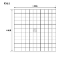
- FIG. 7 is a diagram for explaining high-frequency component extraction processing of the image processing method related to the present invention.
- FIG. 8 is a diagram illustrating an example of an LPF.
- the image processing apparatus applies LPF to the input image (RGB0).
- LPF for example, an averaging filter with 11 pixels ⁇ 11 pixels as shown in FIG. 8 can be adopted.
- the filter size may be changed in accordance with conditions such as the frequency to be extracted and the image size, or a weighted average such as a Gaussian filter may be used.
- the low-frequency component (RGBL) of the input image as shown in FIG. 7A is acquired by this LPF process.
- FIG. 7A shows the low-frequency component (RGBL) of the input image (RGB0) expressed in the RGB color space for convenience of explanation.
- FIG. Only the LPF may be applied.
- the high frequency component (GH) of G of the input image is acquired. The That is, the high frequency component of G is extracted from the input image.
- step S3 Color conversion process to YCrCB color space
- FIG. 9 is a diagram for explaining the conversion process to the YCrCb color space in the image processing method related to the present invention.
- the input image (RGB0) in the RGB color space is converted into the YCrCb color space.
- a luminance component (Y0) and two hue components (Cr0, Cb0) are generated.
- the low frequency component (RGBL) of the input image is also converted to the YCrCb color space.
- This color conversion process generates a luminance component (YL) and two hue components.
- YL luminance component
- RGBL low frequency component
- Step S8 Correction Process for Input Image in YCrCB Color Space
- the image processing apparatus performs correction processing on the input image in the YCrCB color space. That is, the image processing apparatus transplants the high frequency component (GH) of G of the input image to Y (luminance) of the input image.
- GH high frequency component
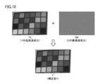
- FIG. 10 is a diagram for explaining a correction process for an input image in the image processing method related to the present invention.
- FIG. 11 is a diagram for explaining the effect of the correction process on the input image in the image processing method related to the present invention.
- the image processing apparatus corrects Y (luminance) of the input image by substituting the high frequency component (GH) of G of the input image instead of the high frequency component of Y (luminance) of the input image.
- the high-frequency component (GH) of the input image is added to the low-frequency component (YL) obtained by removing the high-frequency component from Y (luminance) of the input image.
- a corrected Y (Y ′) that is the luminance of the subsequent input image is generated.
- the correction processing for the input image described above makes it possible to compare the character image, the boundary of the patch, and the like compared to the original Y (luminance) of the input image. It can be seen that the edge is corrected sharply.
- the image processing apparatus uses the corrected Y (Y ′) to return from the YCrCb color space to the RGB color space, thereby generating a corrected RGB image.
- FIG. 12 is a diagram for explaining the color conversion processing to the RGB color space in the image processing method related to the present invention.
- the image processing apparatus generates corrected R and B by adding corrected Y (Y ′) and original Cr and Cb, respectively.
- G is originally a reference color component and does not need to be corrected, so the original value of the input image is used as it is.
- FIG. 13 is a diagram showing an example of a correction result by the image processing method related to the present invention.
- FIG. 14 is an enlarged view of the correction result shown in FIG.
- FIG. 13 shows an image obtained as a result of correcting the input image by the related technology.
- the corrected image shown in FIG. 13 When the corrected image shown in FIG. 13 is viewed, the image appears to be sharpened.
- FIG. 14 when the corrected image is partially enlarged, the red patch portion corrects the high-frequency component. However, it turns out that it is blurred on the contrary. This is caused by the blurring of the R component due to the correction, as shown in the middle part of FIG.
- FIG. 15 and 16 are diagrams for explaining a problem caused by correction by the image processing method related to the present invention.
- FIG. 17 is a diagram for explaining the grayscale direction correlation employed in the embodiment of the present invention.
- the gray patch portion is sharpened (blur is eliminated) by the correction.
- the degree of blur is increased by the correction.
- the patch portion and its peripheral portion are compared for each color.
- both the R component and the G component are thin in the inside of the patch portion, but the periphery thereof is dark, and the relationship regarding the change in light and shade is the same.
- red the inside of the patch part is dark in the R component, but the peripheral part is thin
- the G component the inside of the patch part is thin, but the peripheral part is dark. ing. That is, with respect to red, the relationship of light and shade conversion between the patch portion and the periphery thereof is reversed between the R component and the G component.
- the relationship of light and shade changes between different color components in the same range of the input image is referred to as “light and dark direction correlation degree”.
- a state in which the shade change between different color components is the same or similar, such as the above gray, is called “positive correlation”, and the shade change between different color components, as in the above red.
- a state in which is different or opposite is referred to as “negative correlation”. That is, the solving means according to the present embodiment calculates a gray-scale correlation degree indicating whether the first color component and the second color component are in the same direction or in the opposite direction for the attention area in the input image. Includes processing to calculate.
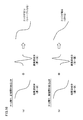
- FIG. 17 shows a conceptual diagram of the positive correlation and the negative correlation related to the grayscale direction correlation degree.
- FIG. 17A in both the R component and the G component, when the corresponding portion changes from a dark state to a light state, a positive correlation is obtained.
- FIG. 17B in the R component, the corresponding portion changes from a dark state to a thin state, while in the G component, the corresponding portion changes from a thin state to a dark state. In such a case, a negative correlation is obtained.
- the high-frequency component used for correction is appropriately corrected so as not to cause blur due to the correction using such a gray-scale correlation. That is, the image processing method according to the present embodiment is directed to a problem that occurs when a method that substitutes a high-frequency component as a high-frequency component of another color component (channel) is employed.
- a method that substitutes a high-frequency component as a high-frequency component of another color component (channel) is employed.
- using the high frequency component of G of the input image as the high frequency component of Y (luminance) corresponds to substituting G as R.
- Embodiment 1 using the above solution will be described. Also in the image processing method according to the first embodiment, as an example, a method is assumed in which a high frequency component of G included in an input image is substituted as a high frequency component of Y (luminance).
- the image processing apparatus has a function of acquiring an input image expressed by a plurality of color components, and a first color component (typically G) for a region of interest in the input image.
- the image processing apparatus uses the high-frequency component of the first color component calculated by the high-frequency component calculation unit in a method corresponding to the grayscale direction correlation degree calculated by the correlation degree calculation unit.
- the color component of is corrected.
- the image processing apparatus according to the first embodiment calculates the degree of contrast in at least two colors, and corrects the blur by switching the use of the high-frequency component for each region.
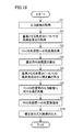
- FIG. 18 is a flowchart showing a procedure of the image processing method according to the first embodiment of the present invention.
- a process for acquiring an input image (step S1) is executed.
- a process (step S2) of acquiring a high frequency component for a reference color component (typically G) among the color components (R, G, B) included in the acquired input image is executed.
- a process for converting the RGB color space of the input image into the YCrCB color space is executed (step S3).
- the processes in steps S1 to S3 are the same as the processes in steps S1 to S3 shown in FIG.
- step S4 a calculation process (step S4) of the light / dark direction correlation degree is executed.
- step S5 which calculates a correction value from the high frequency component about the color component (typically G) used as a reference
- step S6 the correction process with respect to the input image of the YCrCB color space acquired in step S3 is performed using the high frequency component about the reference color component calculated in step S5 (step S6).
- step S7 the process of converting the input image (YCrCB color space) corrected in step S6 into the RGB color space is executed again (step S7), and the corrected image obtained by this process is output (step S10).
- step S10 the corrected image obtained by this process is output
- steps S4 to S7 shown in FIG. 18 will be mainly described in detail. Since the processing contents of steps S1 to S3 and S10 are the same as those described in the related art described above, detailed description will not be repeated.
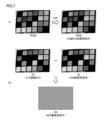
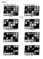
- FIG. 19 is a diagram showing an outline of the grayscale direction correlation degree in the image processing method according to the first embodiment of the present invention.
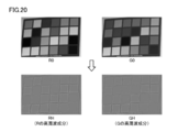
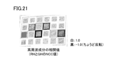
- FIG. 20 and FIG. 21 are diagrams showing a process in the grayscale direction correlation calculation process in the image processing method according to the first embodiment of the present invention.
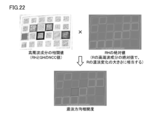
- FIG. 22 is a diagram showing an example of a calculation result of the light / dark direction correlation degree in the image processing method according to the first embodiment of the present invention.
- step S4 of FIG. 18 the gray-scale correlation is calculated in order to avoid the occurrence of a region where blur is caused by correction as shown in FIG. In this case, it is assumed that the gray level correlation degree for R of the input image is calculated.
- the “shading direction correlation degree” is such that, as shown in FIG. 19B, it can be determined whether there is a positive correlation or a negative correlation at an edge (a portion where the change in shading is large). It is data.
- the light / dark direction correlation is expressed as a two-dimensional image.
- the “white” portion is an edge and takes a larger positive value as the positive correlation is stronger.
- the “black” portion is an edge and has a negative negative value as the negative correlation is strong.
- the “gray” portion is a portion that is not an edge, or a portion that has little correlation even if it is an edge, and takes a value in the vicinity of 0 as data.
- the image processing apparatus 1 calculates R and G high-frequency components (RH and GH) of an input image, respectively. Since this high-frequency component calculation method has been described with reference to FIGS. 7 and 8, the detailed contents will not be repeated.
- the image processing apparatus 1 calculates a correlation value between the R high-frequency component (RH) and the G high-frequency component (GH). That is, the image processing apparatus 1 calculates the light and dark direction correlation degree using the high-frequency components of two colors. At this time, the light / dark direction correlation degree is calculated using a correlation value obtained by pattern matching of high-frequency components of two colors.
- the NCC value is calculated as the correlation value of the high frequency component using the NCC (Normalized Cross Correlation) method for the high frequency component (RH) of R and the high frequency component (GH) of G. Is done.
- the NCC method is a kind of pattern matching.
- the NCC value is calculated according to the following equation (1).
- NCC values for the high frequency components (RH and GH) shown in FIG. 20 are as shown in FIG.
- the same shade direction is displayed as whitish, indicating a value close to 1.0, and conversely, the difference in the shade direction is darker, indicating a value close to ⁇ 1.0. It will be.
- the processing may be simplified for speeding up such as calculation every two pixels.
- the processing size does not have to be the same as the LPF size, and the filter size may be adjusted so that the correlation of the target edge density can be calculated appropriately.
- the image processing apparatus is based on the high-frequency component included in the reference color component (typically G) and the color component to be corrected (typically R), The light / dark direction correlation is calculated. More specifically, the image processing apparatus according to the present embodiment calculates the light / dark direction correlation using the NCC method.
- the correlation value (result of NCC value) of the high-frequency component shown in FIG. 21 does not include information about whether or not it is an edge (that is, whether or not the change in shading is large), the absolute value of RH is multiplied. Thus, the light / dark direction correlation degree is calculated.
- the image processing apparatus calculates the light and dark direction correlation degree by multiplying the correlation value of the high frequency component by the absolute value of RH according to the following equation (2).
- Density direction correlation NCC ⁇
- the absolute value of RH is used. That is, the absolute value of the high-frequency component of R corresponds to the magnitude of the change in shading of R.
- the image processing apparatus calculates the density direction correlation degree by multiplying the correlation value by the magnitude of the density change of the second color component (typically, R).
- the second color component typically, R
- step S5 Correction value calculation process from high-frequency component (step S5))
- step S5 a process (step S5) of calculating a correction value from the high frequency component for the reference color component (typically G) is executed.
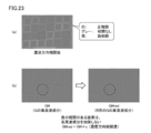
- FIG. 23 is a diagram showing processing for calculating a high-frequency component for correction according to the first embodiment of the present invention.
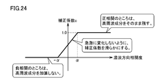
- FIG. 24 is a diagram showing an example of a correction coefficient for calculating a high frequency component for correction according to the first embodiment of the present invention.
- a high frequency component (GHred) of G for correcting R of the input image is calculated using the calculated gray level correlation degree.
- the high frequency component (GHred) of G for correcting R of the input image is generated.
- the G high-frequency component (GHred) is generated according to the following equation (3) using a correction coefficient c as shown in FIG.
- the correction coefficient is set to a linear function for the gray level correlation, The change of the correction coefficient is made smooth.
- the same absolute value of ⁇ and ⁇ is used as the threshold value of the light / dark direction correlation degree, but the negative correlation threshold value is not limited to ⁇ , and an arbitrary value ⁇ ( ⁇ ⁇ 0) is used. It doesn't matter.
- the shade direction correlation degree for the attention area indicates a positive correlation in which the shade direction of the first color component and the second color component is the same direction
- the high frequency component of the first color component is added to the color component of the first color component
- the gray level direction correlation degree for the region of interest has a negative correlation in which the gray level directions of the first color component and the second color component are opposite.
- the second color component is not corrected by the high frequency component of the first color component.
- the grayscale direction correlation degree for the attention area exceeds a predetermined value ⁇ ( ⁇ > 0), it is determined as a positive correlation, and the grayscale direction correlation for the attention area is determined.
- the degree falls below a predetermined value ⁇ ( ⁇ ⁇ 0)
- the grayscale direction correlation degree for the region of interest is in the range from the predetermined value ⁇ to the predetermined value ⁇ , compared to the case of a positive correlation
- the reduced high frequency component of the first color component is added to the second color component.
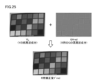
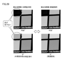
- FIG. 25 is a diagram for describing an input image correction process in the image processing method according to the first embodiment of the present invention.
- FIG. 26 is a diagram for explaining the effect of correction by the input image correction processing shown in FIG.
- the high frequency component (GHred) of G for correcting the R of the input image is transplanted to the luminance (Y′red) of R of the input image. That is, for R of the input image, the corrected luminance (Y′red) for R is calculated using the high frequency component (GHred) of G. More specifically, the luminance (Y′red) is calculated by adding the high frequency component (GHred) of G to the low frequency component (YL) of the luminance of the input image.
- G in the input image is a reference for correction, no correction is made.
- B of the input image is corrected using the high frequency component (GH) of G, as in the related art described above.
- the density direction correlation degree is calculated between G and B of the input image, and based on the calculated density direction correlation degree, A high frequency component (GHblue) of G for correcting B of the input image is calculated. Then, correction may be performed using the calculated G high-frequency component (GHblue). Details of the procedure have been described above and will not be repeated.
- step S7 RGB color space conversion process (step S7)
- the image processing apparatus generates a corrected RGB image by returning from the YCrCb color space to the RGB color space by using the corrected luminance (Y′red) for R.
- FIG. 27 is a diagram for describing color conversion processing into the RGB color space in the image processing method according to the first embodiment of the present invention. As shown in FIG. 27, the image processing apparatus 1 generates corrected R (R ′′) by adding the corrected luminance (Y′red) for R and the original Cr.
- G is originally a reference color component and does not need to be corrected, so the original value of the input image is used as it is.
- the corrected B (B ′) is obtained by adding the luminance (Y ′) and the original Cb in the same procedure as in the related art shown in FIG. Is generated.
- the G high-frequency component (GHblue) for correcting B of the input image is calculated based on the gray-scale correlation, the corrected B (B ′′) is performed in the same procedure as in FIG. ) Is generated.
- FIG. 28 shows an example of a correction result obtained by the image processing method according to the first embodiment of the present invention.
- FIG. 29 is an enlarged view of the correction result shown in FIG.
- the blur red patch portion having a negative correlation
- the correction content can be corrected so as not to blur the region that has a problem in correction (region having negative correlation).
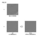
- FIGS 30 and 31 are diagrams showing another example of the correction result by the image processing method according to the first embodiment of the present invention.
- FIG. 30A shows an input image to be processed
- FIG. 30B shows a corrected image obtained by an image processing method according to the related art
- FIG. 30C shows an image processing method according to the present embodiment. The corrected image obtained by is shown.
- the gray level correlation degree as shown in FIG. 31 (a) is calculated, and as shown in FIG. 31 (b), the G of the input image is calculated based on the calculated gray direction correlation degree.
- the G high frequency component (GHred) for correcting the R of the input image is appropriately calculated.
- the processing example in which the high frequency component (GH) of G of the input image is transplanted to Y (luminance) of the input image has been described, but between different color spaces such as the RGB color space and the YCrCb color space.
- the same effect can be obtained in the process of transplanting the high frequency component.
- Patent Document 1 a processing example in which a high frequency component of G is directly added to R and / or B of an input image is adopted.
- the image processing method according to the present embodiment can be applied in the same manner and has the same effect.
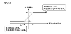
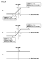
- FIG. 32 is a diagram showing an example of a correction coefficient for calculating a high frequency component for correction according to the modification of the first embodiment of the present invention.
- the correction coefficient c in this negative correlation any value in the range of 0 to 1.0 can be adopted.
- the image processing apparatus does not add or weaken the high frequency component to the negative correlation region.
- the image processing apparatus corrects when the degree of contrast in the light and shade direction for the attention area indicates a positive correlation in which the light and shade directions of the first color component and the second color component are in the same direction.
- the shade direction correlation degree for the attention area indicates a negative correlation in which the shade direction of the first color component and the second color component is opposite.
- the magnitude of the high frequency component for adding the high frequency component of the first color component, which is reduced compared to the case of the positive correlation, to the color component to be corrected is reduced as compared with the case of the positive correlation.
- the image processing method according to the second embodiment is based on the high-frequency component for the reference color component (typically G). Since only the processing content of the processing for calculating the correction value (step S5) is different, detailed description of the other processing will not be repeated. Hereinafter, differences from the first embodiment will be mainly described.
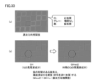
- FIG. 33 is a diagram showing processing for calculating a high-frequency component for correction according to the second embodiment of the present invention.
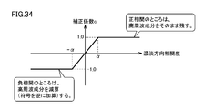
- FIG. 34 shows an example of a correction coefficient for calculating a high frequency component for correction according to the second embodiment of the present invention.
- a G high frequency component (GHred2) for correcting R of the input image is calculated using the calculated gray level correlation degree.
- Such a high frequency component (GHred2) of G for correcting the R of the input image is generated.
- a correction coefficient c as shown in FIG. 34 is used for the generation of the G high frequency component (GHred).
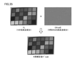
- FIG. 35 is a diagram for describing input image correction processing in the image processing method according to the second embodiment of the present invention.
- FIG. 36 is a diagram for explaining the effect of correction by the input image correction processing shown in FIG.
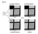
- FIG. 37 shows an example of a correction result obtained by the image processing method according to the second embodiment of the present invention.
- the high frequency component of G (GHred2) for correcting R of the input image is transplanted to the luminance (Y′red) of R of the input image. That is, for R of the input image, the corrected luminance (Y′red2) for R is calculated using the high-frequency component of G (GHred2). More specifically, the luminance (Y′red2) is calculated by adding the high frequency component (GHred2) of G to the low frequency component (YL) of the luminance of the input image.
- the edge of the red patch portion where the blur has occurred due to the negative correlation as shown in FIG. 15 is shown in FIG. Edges are corrected in the opposite direction to the example. As a result, as shown in FIG. 37, the red patch portion can be corrected to be sharper.
- the image processing apparatus subtracts the high frequency component from the negative correlation area.
- the image processing apparatus corrects when the degree of contrast in the light and shade direction for the attention area indicates a positive correlation in which the light and shade directions of the first color component and the second color component are in the same direction. While the high-frequency component of the first color component is added to the color component of the first color component, the correlation in the grayscale direction for the region of interest is negative in which the grayscale directions of the first color component and the second color component are opposite. When showing the correlation, the high frequency component of the first color component is subtracted from the color component to be corrected.
- Embodiment 3 In the first and second embodiments described above, the correction method using the high-frequency component is changed (not adding the high-frequency component, depending on whether or not the gray-scale direction correlation is a negative correlation for the entire image. A processing example of weakening and adding in reverse has been described.
- an input image to be processed is divided into a plurality of partial areas, and it is determined whether each partial area is an area with a high frequency component or a low area. . Then, for a region having a high frequency component, the image processing method according to the related art described above is applied, and correction is performed using the high frequency component of the input image regardless of the grayscale direction correlation degree.
- the image processing method according to the first or second embodiment described above is applied to a region with a small amount of high-frequency components, and the correction method using the high-frequency components is changed depending on the density direction correlation.
- FIG. 38 is a diagram for describing the outline of the image processing method according to the third embodiment of the present invention.
- FIG. 39 shows an example of the correction coefficient used in the image processing method according to the third embodiment of the present invention.
- the image processing apparatus 1 first divides the input image into a plurality of partial areas (red dotted line areas). Each partial area is set to a size of 50 pixels ⁇ 50 pixels, for example. Subsequently, the image processing apparatus 1 determines, for each partial region, whether the region has a high frequency component or a region with a low high frequency component. Then, the image processing apparatus 1 applies the image processing method according to the related technique shown in FIG. 5 to a region having a high frequency component, and applies the image processing method according to the above-described first or second embodiment to a region having a low high frequency component. Apply. That is, the image processing apparatus 1 changes the processing of the high-frequency component only for the region where the high-frequency component is small according to the contrast direction in the light / dark direction (does not add, weaken, or add the high-frequency component).
- the image processing apparatus 1 performs correction using the correction coefficient c shown in FIG. 39 (a) or 39 (b) for a region with a low high-frequency component in the input image, and the high-frequency component in the input image. For regions with a large amount of correction, correction is performed using the correction coefficient c shown in FIG.
- the correction coefficient c shown in FIG. 39 (c) is always “1” without depending on the light / dark direction correlation degree.
- the determination as to whether the high-frequency component in the partial region set in the input image is large or small can be made. It may be determined based on whether or not the absolute value of the high-frequency component (RH) is greater than or equal to a threshold value (for example, 10). According to this determination method, a region in which the absolute value of the R high-frequency component (RH) is greater than or equal to the threshold value is determined as the R high-frequency region, and the ratio of the high-frequency region to the partial region is equal to or less than a certain value (for example, , 50% or less), it is determined that the region has few high-frequency components. On the other hand, if the ratio of the high frequency region to the partial region exceeds the certain value (for example, more than 50%), it is determined that the region has a high frequency component.
- a threshold value for example, 10
- the image processing apparatus determines whether or not the attention area includes a lot of high-frequency components.
- the region of interest is determined by a predetermined method without depending on the shade direction correlation degree.
- the color component to be corrected for the region is corrected. That is, the correction method using the high-frequency component is changed (not added / weakened / subtracted) only in a region having a negative correlation and in a low-frequency region (a region having a low high-frequency component).
- Embodiment 4 In the first to third embodiments described above, the example in which the NCC method is used to calculate the light / dark direction correlation degree has been described. However, the light / dark direction correlation degree can also be calculated using other methods.
- the light / dark direction correlation degree is calculated using the NCC method, but according to the following equation (4), the correlation value of the high frequency component (correlation value between RH and GH) is calculated. Also good. Since this equation (4) does not include the square root calculation, the calculation process can be speeded up.
- the absolute value of RH (information on whether it is an edge of R (whether the change in shading is large)) is obtained from the result obtained by the expression (4) according to the following expression (5), as in the first embodiment.
- the shade direction correlation degree is calculated by multiplying.
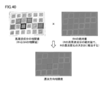
- FIG. 40 is a diagram showing an example of the calculation result of the light / dark direction correlation degree in the image processing method according to the fourth embodiment of the present invention. As shown in FIG. 40, it can be seen that the same result as the grayscale correlation (see FIG. 22) calculated using the NCC method is obtained.
- the method of calculating the “correlation value of the high frequency component” used when calculating the density direction correlation is not limited to the NCC method, and is opposite to the case where the edge density change direction is the same. Any other method or process can be adopted as long as a correlation value that reverses the sign between the cases can be calculated.
- the high frequency component of the color having the best MTF characteristic for example, G
- another color for example, R
- blurring can be corrected in a more natural manner.
Landscapes
- Engineering & Computer Science (AREA)
- Physics & Mathematics (AREA)
- General Physics & Mathematics (AREA)
- Theoretical Computer Science (AREA)
- Multimedia (AREA)
- Signal Processing (AREA)
- Image Processing (AREA)
- Studio Devices (AREA)
- Geometry (AREA)
- Color Image Communication Systems (AREA)
Description
本発明の別の実施の形態に従う画像処理方法は、少なくとも第1および第2の色成分を含む複数の色成分で表現された入力画像を取得するステップと、入力画像における注目領域について、第1の色成分と第2の色成分の濃淡方向が同一方向であるか逆方向であるかを示す濃淡方向相関度を算出するステップと、注目領域について、第1の色成分の高周波成分を算出するステップと、濃淡方向相関度に応じた方法で、第1の色成分の高周波成分を用いて、注目領域についての第2の色成分を補正するステップとを含む。
本発明の実施の形態に従う画像処理装置は、典型的には、光学系の軸上色収差などにより入力画像がぼけを含む場合、最もMTF特性の良い色(例えば、G)の高周波成分を、他の色(例えば、R)の高周波成分を用いて補正するような画像補正処理に適している。
まず、本発明の実施の形態に従う画像処理装置の構成について説明する。
図1は、本発明の実施の形態に従う画像処理装置1の基本的構成を示すブロック図である。図1を参照して、画像処理装置1は、撮像部2と、画像処理部3と、画像出力部4とを含む。図1に示す画像処理装置1においては、撮像部2が被写体を撮像することで画像(以下、「入力画像」とも称す。)を取得し、画像処理部3がこの取得された入力画像に対して後述するような画像処理を行なうことで、当該入力画像に含まれるぼけを補正する。そして、画像出力部4は、この補正後の入力画像(以下、単に「補正後画像」とも称す。)を表示デバイスなどへ出力する。
色空間変換部32は、処理対象の入力画像の色空間を変換する。具体的には、色空間変換部32は、RGB色空間の入力画像をYCrCb色空間の画像に変換する。
RGB補正画像生成部38は、エッジ補正後の入力画像をRGB色空間の画像に再度変換して出力する。
図1に示す画像処理装置1は、各部を独立に構成することもできるが、汎用的には、以下に説明するデジタルカメラやパーソナルコンピューターなどとして具現化される場合が多い。そこで、本実施の形態に従う画像処理装置1の具現化例について説明する。
図2は、図1に示す画像処理装置1を具現化したデジタルカメラ100の構成を示すブロック図である。図2において、図1に示す画像処理装置1を構成するそれぞれのブロックに対応するコンポーネントには、図1と同一の参照符号を付している。
図2に示すデジタルカメラ100は、本実施の形態に従う画像処理装置1の全体を単体の装置として実装したものである。すなわち、ユーザーは、デジタルカメラ100を用いて被写体を撮像することで、画像表示部108において当該被写体を立体的に視認することができる。
図3は、図1に示す画像処理装置1を具現化したパーソナルコンピューター200の構成を示すブロック図である。図3に示すパーソナルコンピューター200では、入力画像を取得するための撮像部2が搭載されておらず、任意の撮像部2によって取得された入力画像が外部から入力される構成となっている。このような構成であっても、本発明の実施の形態に従う画像処理装置1に含まれ得る。なお、図3においても、図1に示す画像処理装置1を構成するそれぞれのブロックに対応するコンポーネントには、図1と同一の参照符号を付している。
本実施の形態に従う画像処理装置および画像処理方法では、典型的には、光学系に生じる色収差(軸上色収差)を補正する。
まず、本実施の形態に従う画像処理方法の内容についての理解を容易にするために、本発明に関連する画像処理方法の内容について先に説明する。
画像処理装置は、カメラで被写体を撮像するなどして、入力画像を取得する。図6は、本発明に関連する画像処理方法の処理対象となる入力画像の一例を示す図である。図6(a)には、RGB色空間で表現した入力画像(RGB0)の一例を示し、図6(b),(c),(d)には、R、G、Bの各濃淡画像(R0、G0、B0)の一例を示す。
(d2:高周波成分の取得(ステップS2))
画像処理装置は、処理対象の入力画像に含まれる色成分(R、G、B)のうち基準となる色成分(典型的には、G)についての高周波成分を取得する。具体的には、入力画像に対してLPF(ローパスフィルター)をかけて低周波成分を抽出するとともに、入力画像からこの抽出した低周波成分を減算することで、高周波成分を抽出する。
画像処理装置は、RGB色空間の入力画像およびその低周波成分のそれぞれを、事後の補正処理のために、YCrCb色空間へ変換する。
次に、画像処理装置は、YCrCB色空間の入力画像に対して補正処理を行なう。すなわち、画像処理装置は、入力画像のGの高周波成分(GH)を入力画像のY(輝度)へ移植する。
最後に、画像処理装置は、補正後Y(Y’)を用いて、YCrCb色空間からRGB色空間へ戻すことで、補正後のRGB画像を生成する。
図13は、本発明に関連する画像処理方法による補正結果の一例を示す図である。図14は、図13に示す補正結果の拡大図である。
本願発明者は、上述した関連技術において、図14に示すような課題が生じることを見出すとともに、その原因について新たな知見を得た。その上で、本願発明者は、この新たな知見に基づいて、本願の技術思想に想到したものである。以下、これらの内容について説明する。
次に、上述のような解決手段を用いた実施の形態1について説明する。実施の形態1に従う画像処理方法においても、一例として、入力画像に含まれるGの高周波成分をY(輝度)の高周波成分として代用する方法を想定する。
図18は、本発明の実施の形態1に従う画像処理方法の手順を示すフローチャートである。図18を参照して、まず入力画像を取得する処理(ステップS1)が実行される。続いて、当該取得した入力画像に含まれる色成分(R、G、B)のうち基準となる色成分(典型的には、G)についての高周波成分を取得する処理(ステップS2)が実行される。さらに、入力画像のRGB色空間をYCrCB色空間へ変換する処理が実行される(ステップS3)。このステップS1~S3の処理は、図5に示すステップS1~S3の処理と同様である。
次に、濃淡方向相関度の算出処理の詳細について説明する。

ここでは、RのエッジがGのエッジに対してどのような相関があるかを算出しているため、RHの絶対値を用いている。すなわち、Rの高周波成分の絶対値がRの濃淡変化の大きさに相当する。
次に、基準となる色成分(典型的には、G)についての高周波成分から補正値を算出する処理(ステップS5)が実行される。
図24に示す補正係数cに関して、正相関のところはGの高周波成分をそのまま残すために、濃淡方向相関度がα(α>0)を超える場合には、補正係数c=1を採用する。一方、負相関のところはGの高周波成分を加算しないために、濃淡方向相関度が-αを下回る場合には、補正係数c=0を採用する。正相関と負相関との間で急激な変化を避けるために、濃淡方向相関度が-αからαの範囲にある場合には、補正係数を濃淡方向相関度についての一次関数に設定して、補正係数の変化を滑らかにしている。なお、ここでは濃淡方向相関度の閾値としてαと-αの絶対値が同じ値を用いたが、負相関の閾値としては、-αに限らず、任意の値β(β<0)を用いても構わない。
次に、上述のような処理によって算出された、入力画像のRを補正するためのGの高周波成分(GHred)を用いて、入力画像に対する補正処理が実行される。
最後に、画像処理装置は、R用の補正後の輝度(Y’red)を用いて、YCrCb色空間からRGB色空間へ戻すことで、補正後のRGB画像を生成する。
図28は、本発明の実施の形態1に従う画像処理方法による補正結果の一例を示す図である。図29は、図28に示す補正結果の拡大図である。
上述の説明においては、入力画像のRについて、濃淡方向相関度を算出するとともに、当該算出した濃淡方向相関度に基づいて入力画像のRを補正するためのGの高周波成分(GHred)を算出した上で、入力画像のRを補正する例を記載した。これに代えて、あるいは、これに代えて、入力画像のBに対しても同様の画像処理方法を適用できることは自明である。この場合においても、同様の効果が得られることも自明である。
光学系の軸上色収差などにより入力画像がぼけを含む場合、最もMTF特性の良い色(例えば、G)の高周波成分を、他の色(例えば、R)の高周波成分に単純に移植(加算)することで、このようなぼけを補正しようとすると、一部の領域で逆にぼけたり、エッジに不自然な画像処理がかかったりすることがある。これに対して、本実施の形態においては、色毎に濃淡変化の方向が同じであるか否か、すなわち濃淡方向相関度を評価することで、このような他の色の高周波成分に移植(加算)してよいか否かを判断することで、ぼけの発生といった副作用が生じないように、画像補正を行なうことができる。
上述の実施の形態1においては、濃淡方向相関度が負相関の場合に、高周波成分を加算しない、または弱める処理例について説明した。これに対して、実施の形態2においては、濃淡方向相関度が負相関の場合に、高周波成分を減算する処理例について説明する。
上述の実施の形態1および2においては、画像全体に対して、濃淡方向相関度が負相関であるか否かに応じて、高周波成分を用いた補正方法を変更する(高周波成分を加算しない、弱める、逆に加算する)処理例について説明した。
上述の実施の形態1~3においては、濃淡方向相関度の算出にNCC法を用いる例について説明したが、これ以外の方法を用いて濃淡方向相関度を算出することもできる。

図40は、本発明の実施の形態4に従う画像処理方法における濃淡方向相関度の算出結果の一例を示す図である。図40に示すように、NCC法を用いて算出した濃淡方向相関度(図22参照)と同様の結果が得られることがわかる。
本発明の実施の形態によれば、光学系の軸上色収差などにより入力画像がぼけを含む場合、最もMTF特性の良い色(例えば、G)の高周波成分を、他の色(例えば、R)の高周波成分に単純に移植(加算)することで、このようなぼけを補正しようとすると、一部の領域で逆にぼけたり、エッジに不自然な画像処理がかかったりすることがある。これに対して、本実施の形態によれば、より自然なかたちでぼけを補正できる。
Claims (13)
- 少なくとも第1および第2の色成分を含む複数の色成分で表現された入力画像を取得する取得部と、
前記入力画像における注目領域について、前記第1の色成分と前記第2の色成分の濃淡方向が同一方向であるか逆方向であるかを示す濃淡方向相関度を算出する相関度算出部と、
前記注目領域について、前記第1の色成分の高周波成分を算出する高周波成分算出部と、
前記相関度算出部によって算出された濃淡方向相関度に応じた方法で、前記高周波成分算出部によって算出された前記第1の色成分の高周波成分を用いて前記注目領域についての前記第2の色成分を補正する補正部とを備える、画像処理装置。 - 前記補正部は、
前記注目領域についての前記濃淡方向相関度が、前記第1の色成分と前記第2の色成分の濃淡方向が同一方向である正相関を示すときに、前記第2の色成分に対して前記第1の色成分の高周波成分を加算し、
前記注目領域についての前記濃淡方向相関度が、前記第1の色成分と前記第2の色成分の濃淡方向が逆方向である負相関を示すときに、前記第1の色成分の高周波成分による前記第2の色成分の補正を行なわない、請求項1に記載の画像処理装置。 - 前記補正部は、
前記注目領域についての前記濃淡方向相関度が所定値α(α>0)を超えるときに前記正相関と判断し、前記注目領域についての前記濃淡方向相関度が所定値β(β<0)を下回るときに前記負相関と判断し、
前記注目領域についての前記濃淡方向相関度が所定値αから所定値βの範囲にあるときに、前記正相関の場合と比較して低減された前記第1の色成分の高周波成分を前記第2の色成分に対して加算する、請求項2に記載の画像処理装置。 - 前記補正部は、
前記注目領域についての前記濃淡方向相関度が、前記第1の色成分と前記第2の色成分の濃淡方向が同一方向である正相関を示すときに、前記第2の色成分に対して前記第1の色成分の高周波成分を加算し、
前記注目領域についての前記濃淡方向相関度が、前記第1の色成分と前記第2の色成分の濃淡方向が逆方向である負相関を示すときに、前記正相関の場合と比較して低減された前記第1の色成分の高周波成分を前記第2の色成分に対して加算する、請求項1に記載の画像処理装置。 - 前記補正部は、
前記注目領域についての前記濃淡方向相関度が、前記第1の色成分と前記第2の色成分の濃淡方向が同一方向である正相関を示すときに、前記第2の色成分に対して前記第1の色成分の高周波成分を加算し、
前記注目領域についての前記濃淡方向相関度が、前記第1の色成分と前記第2の色成分の濃淡方向が逆方向である負相関を示すときに、前記第2の色成分に対して前記第1の色成分の高周波成分を減算する、請求項1に記載の画像処理装置。 - 前記補正部は、
前記注目領域に高周波成分が多く含まれているか否かを判断し、
前記注目領域に高周波成分が多く含まれていない場合には、前記濃淡方向相関度に応じた方法で前記注目領域についての前記第2の色成分を補正する一方、
前記注目領域に高周波成分が多く含まれている場合には、前記濃淡方向相関度に依存せず、予め定められた方法で前記注目領域についての前記第2の色成分を補正する、請求項1~5のいずれか1項に記載の画像処理装置。 - 前記補正部は、前記第2の色成分のMTF特性のうち、前記第1の色成分のMTF特性に比較して劣化している周波数帯域を補正する、請求項1~6のいずれか1項に記載の画像処理装置。
- 前記相関度算出部は、前記第1の色成分および前記第2の色成分に含まれる高周波成分に基づいて、前記濃淡方向相関度を算出する、請求項1~7のいずれか1項に記載の画像処理装置。
- 前記相関度算出部は、前記第1の色成分および前記第2の色成分に含まれる高周波成分をパターンマッチングして得られた相関値を用いて、前記濃淡方向相関度を算出する、請求項8に記載の画像処理装置。
- 前記相関度算出部は、前記相関値に第2の色成分の濃淡変化の大きさを乗じることで、前記濃淡方向相関度を算出する、請求項9に記載の画像処理装置。
- 前記相関度算出部は、NCC法を用いて前記相関値を算出する、請求項9または10に記載の画像処理装置。
- 少なくとも第1および第2の色成分を含む複数の色成分で表現された入力画像を取得するステップと、
前記入力画像における注目領域について、前記第1の色成分と前記第2の色成分の濃淡方向が同一方向であるか逆方向であるかを示す濃淡方向相関度を算出するステップと、
前記注目領域について、前記第1の色成分の高周波成分を算出するステップと、
前記濃淡方向相関度に応じた方法で、前記第1の色成分の高周波成分を用いて、前記注目領域についての前記第2の色成分を補正するステップとを備える、画像処理方法。 - コンピューターに画像処理を実行させる画像処理プログラムであって、前記画像処理プログラムは、前記コンピューターに、
少なくとも第1および第2の色成分を含む複数の色成分で表現された入力画像を取得するステップと、
前記入力画像における注目領域について、前記第1の色成分と前記第2の色成分の濃淡方向が同一方向であるか逆方向であるかを示す濃淡方向相関度を算出するステップと、
前記注目領域について、前記第1の色成分の高周波成分を算出するステップと、
前記濃淡方向相関度に応じた方法で、前記第1の色成分の高周波成分を用いて、前記注目領域についての前記第2の色成分を補正するステップとを実行させる、画像処理プログラム。
Priority Applications (2)
| Application Number | Priority Date | Filing Date | Title |
|---|---|---|---|
| US14/410,809 US9336575B2 (en) | 2012-06-25 | 2013-06-17 | Image processing apparatus, image processing method, and image processing program |
| JP2014522548A JP6213466B2 (ja) | 2012-06-25 | 2013-06-17 | 画像処理装置、画像処理方法および画像処理プログラム |
Applications Claiming Priority (2)
| Application Number | Priority Date | Filing Date | Title |
|---|---|---|---|
| JP2012142262 | 2012-06-25 | ||
| JP2012-142262 | 2012-06-25 |
Publications (1)
| Publication Number | Publication Date |
|---|---|
| WO2014002811A1 true WO2014002811A1 (ja) | 2014-01-03 |
Family
ID=49782972
Family Applications (1)
| Application Number | Title | Priority Date | Filing Date |
|---|---|---|---|
| PCT/JP2013/066580 Ceased WO2014002811A1 (ja) | 2012-06-25 | 2013-06-17 | 画像処理装置、画像処理方法および画像処理プログラム |
Country Status (3)
| Country | Link |
|---|---|
| US (1) | US9336575B2 (ja) |
| JP (1) | JP6213466B2 (ja) |
| WO (1) | WO2014002811A1 (ja) |
Cited By (1)
| Publication number | Priority date | Publication date | Assignee | Title |
|---|---|---|---|---|
| US12387342B2 (en) | 2019-05-30 | 2025-08-12 | Panasonic Intellectual Property Management Co., Ltd. | Image processing method, image processing device, and recording medium for obtaining a composite image by synthesizing a high-frequency image and one or more color images |
Families Citing this family (4)
| Publication number | Priority date | Publication date | Assignee | Title |
|---|---|---|---|---|
| JP6516446B2 (ja) * | 2014-11-14 | 2019-05-22 | キヤノン株式会社 | 情報処理装置、情報処理方法、及びプログラム |
| KR102423234B1 (ko) * | 2015-10-22 | 2022-07-22 | 삼성디스플레이 주식회사 | 표시 장치 및 이를 포함하는 휘도 보정 시스템 |
| TWI741437B (zh) * | 2019-12-09 | 2021-10-01 | 財團法人資訊工業策進會 | 影像分析裝置與影像分析方法 |
| CN113395441A (zh) * | 2020-03-13 | 2021-09-14 | 华为技术有限公司 | 图像留色方法及设备 |
Citations (3)
| Publication number | Priority date | Publication date | Assignee | Title |
|---|---|---|---|---|
| JPH05344338A (ja) * | 1992-06-08 | 1993-12-24 | Dainippon Screen Mfg Co Ltd | カラー画像の輪郭強調方法 |
| JP2009206552A (ja) * | 2008-02-26 | 2009-09-10 | Victor Co Of Japan Ltd | 画像処理装置 |
| JP2010028374A (ja) * | 2008-07-17 | 2010-02-04 | Toshiba Design & Manufacturing Service Corp | 画像処理装置および画像信号の補間処理方法、画像処理プログラム |
Family Cites Families (5)
| Publication number | Priority date | Publication date | Assignee | Title |
|---|---|---|---|---|
| JP2005354610A (ja) * | 2004-06-14 | 2005-12-22 | Canon Inc | 画像処理装置、画像処理方法および画像処理プログラム |
| JP4797478B2 (ja) | 2005-07-14 | 2011-10-19 | 株式会社ニコン | 画像処理装置 |
| WO2007007878A1 (ja) | 2005-07-14 | 2007-01-18 | Nikon Corporation | 画像処理装置および画像処理方法 |
| JP4492694B2 (ja) * | 2007-12-20 | 2010-06-30 | セイコーエプソン株式会社 | 集積回路装置、電気光学装置及び電子機器 |
| US8463035B2 (en) * | 2009-05-28 | 2013-06-11 | Gentex Corporation | Digital image processing for calculating a missing color value |
-
2013
- 2013-06-17 US US14/410,809 patent/US9336575B2/en not_active Expired - Fee Related
- 2013-06-17 WO PCT/JP2013/066580 patent/WO2014002811A1/ja not_active Ceased
- 2013-06-17 JP JP2014522548A patent/JP6213466B2/ja not_active Expired - Fee Related
Patent Citations (3)
| Publication number | Priority date | Publication date | Assignee | Title |
|---|---|---|---|---|
| JPH05344338A (ja) * | 1992-06-08 | 1993-12-24 | Dainippon Screen Mfg Co Ltd | カラー画像の輪郭強調方法 |
| JP2009206552A (ja) * | 2008-02-26 | 2009-09-10 | Victor Co Of Japan Ltd | 画像処理装置 |
| JP2010028374A (ja) * | 2008-07-17 | 2010-02-04 | Toshiba Design & Manufacturing Service Corp | 画像処理装置および画像信号の補間処理方法、画像処理プログラム |
Cited By (1)
| Publication number | Priority date | Publication date | Assignee | Title |
|---|---|---|---|---|
| US12387342B2 (en) | 2019-05-30 | 2025-08-12 | Panasonic Intellectual Property Management Co., Ltd. | Image processing method, image processing device, and recording medium for obtaining a composite image by synthesizing a high-frequency image and one or more color images |
Also Published As
| Publication number | Publication date |
|---|---|
| US20150187054A1 (en) | 2015-07-02 |
| US9336575B2 (en) | 2016-05-10 |
| JPWO2014002811A1 (ja) | 2016-05-30 |
| JP6213466B2 (ja) | 2017-10-18 |
Similar Documents
| Publication | Publication Date | Title |
|---|---|---|
| US20250117898A1 (en) | Image processing method, image processing apparatus, image processing system, and memory medium | |
| EP1931130B1 (en) | Image processing apparatus, image processing method, and program | |
| KR101340518B1 (ko) | 영상의 색수차 보정 방법 및 장치 | |
| US8553978B2 (en) | System and method for providing multi resolution purple fringing detection and correction | |
| RU2523028C2 (ru) | Устройство обработки изображения, устройство захвата изображения и способ обработки изображения | |
| JP5235642B2 (ja) | 画像処理装置およびその方法 | |
| US9071761B2 (en) | Information processing apparatus, information processing method, program, and imaging apparatus including optical microscope | |
| WO2011122283A1 (ja) | 画像処理装置、およびそれを用いた撮像装置 | |
| US9185265B2 (en) | Image processing method and image processing apparatus for performing a tone correction to acquire a combined image | |
| KR20090027060A (ko) | 영상 복원 장치 및 복원 방법 | |
| JP6213466B2 (ja) | 画像処理装置、画像処理方法および画像処理プログラム | |
| US10217193B2 (en) | Image processing apparatus, image capturing apparatus, and storage medium that stores image processing program | |
| Nikonorov et al. | Comparative evaluation of deblurring techniques for Fresnel lens computational imaging | |
| JP7075773B2 (ja) | 画像処理装置、顕微鏡システム、画像処理方法および画像処理プログラム | |
| JP2015115733A (ja) | 画像処理方法、画像処理装置、撮像装置および画像処理プログラム | |
| JP2015122634A (ja) | 画像処理装置、撮像装置、プログラム及び画像処理方法 | |
| JP5274697B2 (ja) | 画像処理装置及び画像処理方法 | |
| JP6436840B2 (ja) | 画像処理装置、撮像装置、画像処理方法、画像処理プログラム、および、記憶媒体 | |
| Ju et al. | Color fringe removal in narrow color regions of digital images | |
| Gautam et al. | An advanced visibility restoration technique for underwater images | |
| JP6238673B2 (ja) | 画像処理装置、撮像装置、撮像システム、画像処理方法、画像処理プログラム、および、記憶媒体 | |
| JP5630105B2 (ja) | 画像処理装置、撮像装置および画像処理プログラム | |
| JP6468791B2 (ja) | 画像処理装置、撮像装置、画像処理システム、画像処理方法および画像処理プログラム | |
| JP2019016222A (ja) | 画像処理装置およびその制御方法 | |
| JP6331363B2 (ja) | 被写体特定装置、撮像装置およびプログラム |
Legal Events
| Date | Code | Title | Description |
|---|---|---|---|
| 121 | Ep: the epo has been informed by wipo that ep was designated in this application |
Ref document number: 13809439 Country of ref document: EP Kind code of ref document: A1 |
|
| ENP | Entry into the national phase |
Ref document number: 2014522548 Country of ref document: JP Kind code of ref document: A |
|
| WWE | Wipo information: entry into national phase |
Ref document number: 14410809 Country of ref document: US |
|
| NENP | Non-entry into the national phase |
Ref country code: DE |
|
| 122 | Ep: pct application non-entry in european phase |
Ref document number: 13809439 Country of ref document: EP Kind code of ref document: A1 |