WO2014002905A1 - 切削工具把持具 - Google Patents
切削工具把持具 Download PDFInfo
- Publication number
- WO2014002905A1 WO2014002905A1 PCT/JP2013/067119 JP2013067119W WO2014002905A1 WO 2014002905 A1 WO2014002905 A1 WO 2014002905A1 JP 2013067119 W JP2013067119 W JP 2013067119W WO 2014002905 A1 WO2014002905 A1 WO 2014002905A1
- Authority
- WO
- WIPO (PCT)
- Prior art keywords
- cutting tool
- tool
- cutting
- sleeve
- holding tube
- Prior art date
- Legal status (The legal status is an assumption and is not a legal conclusion. Google has not performed a legal analysis and makes no representation as to the accuracy of the status listed.)
- Ceased
Links
Images




Classifications
-
- B—PERFORMING OPERATIONS; TRANSPORTING
- B23—MACHINE TOOLS; METAL-WORKING NOT OTHERWISE PROVIDED FOR
- B23B—TURNING; BORING
- B23B27/00—Tools for turning or boring machines; Tools of a similar kind in general; Accessories therefor
- B23B27/007—Tools for turning or boring machines; Tools of a similar kind in general; Accessories therefor for internal turning
-
- B—PERFORMING OPERATIONS; TRANSPORTING
- B23—MACHINE TOOLS; METAL-WORKING NOT OTHERWISE PROVIDED FOR
- B23B—TURNING; BORING
- B23B29/00—Holders for non-rotary cutting tools; Boring bars or boring heads; Accessories for tool holders
- B23B29/02—Boring bars
- B23B29/022—Boring bars with vibration reducing means
-
- B—PERFORMING OPERATIONS; TRANSPORTING
- B23—MACHINE TOOLS; METAL-WORKING NOT OTHERWISE PROVIDED FOR
- B23B—TURNING; BORING
- B23B29/00—Holders for non-rotary cutting tools; Boring bars or boring heads; Accessories for tool holders
- B23B29/04—Tool holders for a single cutting tool
- B23B29/12—Special arrangements on tool holders
-
- B—PERFORMING OPERATIONS; TRANSPORTING
- B23—MACHINE TOOLS; METAL-WORKING NOT OTHERWISE PROVIDED FOR
- B23B—TURNING; BORING
- B23B27/00—Tools for turning or boring machines; Tools of a similar kind in general; Accessories therefor
- B23B27/002—Tools for turning or boring machines; Tools of a similar kind in general; Accessories therefor with vibration damping means
-
- B—PERFORMING OPERATIONS; TRANSPORTING
- B23—MACHINE TOOLS; METAL-WORKING NOT OTHERWISE PROVIDED FOR
- B23B—TURNING; BORING
- B23B29/00—Holders for non-rotary cutting tools; Boring bars or boring heads; Accessories for tool holders
- B23B29/04—Tool holders for a single cutting tool
-
- B—PERFORMING OPERATIONS; TRANSPORTING
- B23—MACHINE TOOLS; METAL-WORKING NOT OTHERWISE PROVIDED FOR
- B23Q—DETAILS, COMPONENTS, OR ACCESSORIES FOR MACHINE TOOLS, e.g. ARRANGEMENTS FOR COPYING OR CONTROLLING; MACHINE TOOLS IN GENERAL CHARACTERISED BY THE CONSTRUCTION OF PARTICULAR DETAILS OR COMPONENTS; COMBINATIONS OR ASSOCIATIONS OF METAL-WORKING MACHINES, NOT DIRECTED TO A PARTICULAR RESULT
- B23Q11/00—Accessories fitted to machine tools for keeping tools or parts of the machine in good working condition or for cooling work; Safety devices specially combined with or arranged in, or specially adapted for use in connection with, machine tools
- B23Q11/0032—Arrangements for preventing or isolating vibrations in parts of the machine
-
- B—PERFORMING OPERATIONS; TRANSPORTING
- B23—MACHINE TOOLS; METAL-WORKING NOT OTHERWISE PROVIDED FOR
- B23B—TURNING; BORING
- B23B2229/00—Details of boring bars or boring heads
-
- B—PERFORMING OPERATIONS; TRANSPORTING
- B23—MACHINE TOOLS; METAL-WORKING NOT OTHERWISE PROVIDED FOR
- B23B—TURNING; BORING
- B23B2250/00—Compensating adverse effects during turning, boring or drilling
- B23B2250/16—Damping of vibrations
-
- B—PERFORMING OPERATIONS; TRANSPORTING
- B23—MACHINE TOOLS; METAL-WORKING NOT OTHERWISE PROVIDED FOR
- B23B—TURNING; BORING
- B23B2260/00—Details of constructional elements
- B23B2260/026—Bushings, e.g. adapter sleeves
Definitions
- the present invention relates to a cutting tool gripping tool for attaching a cutting tool to a cutting machine, and more particularly to a cutting tool gripping tool for attaching to a cutting machine after inserting and fixing one end of a rod-shaped cutting tool in an attachment hole.
- a fitting hole along the axis of a cylindrical gripping tool body made of steel or the like is used to prevent vibration generated in a boring bar during cutting from being directly transmitted to the cutting tool gripping tool.
- a cylindrical sleeve made of a damping member is inserted into the inner peripheral surface of the sleeve, and a shank portion of a boring bar is inserted into the inner peripheral surface of the sleeve and pressed and fixed with a clamp screw.
- the outer peripheral surface of the shank part opposite to the clamp screw is used as a pressing surface, and a damping member is interposed between the pressing surface and the inner surface of the fitting hole facing the boring.
- the vibration generated in the bar is attenuated and absorbed by the damping member to suppress the swing of the boring bar, and in particular, “batter vibration” due to resonance between the shank portion and the gripper main body is prevented.
- the damping member that can be used for the pressing surface portion include aluminum, copper, zinc, brass, an alloy containing these as a main component, a damping steel plate, and the like.
- the core member is screwed so as to be fitted along the axial center of the metal sleeve, and the shank of the cutting tool is fitted and attached to the tool holding hole of the core member. It is disclosed that pure magnesium or a magnesium alloy that is lightweight and excellent in vibration absorption can be used for the core member. By making the sleeve and the core member in the cutting tool gripping tool separate, the core member tries to absorb vibration transmitted from the cutting tool to the mounting base of the cutting machine via the cutting tool gripping tool during the cutting process.
- Patent Document 3 discloses that a damping member is interposed between a cutting tool and a tool base that presses and fixes the cutting tool.
- a damping member is interposed between a cutting tool and a tool base that presses and fixes the cutting tool.
- the higher the damping coefficient the more the vibration during cutting is performed.
- the damping performance and the rigidity and strength expressed by the tensile strength are in a trade-off relationship. It states that the vibration of the cutting tool is intensified and the machining accuracy is reduced.
- the damping member a metal material having a tensile strength of 500 to 650 MPa and a logarithmic attenuation rate of 0.2 to 0.35, for example, Mn is used as a base, and the basic composition is Cu: Damping alloys containing 20 ⁇ 5%, Ni: 5 ⁇ 3%, and Fe: 2 ⁇ 1% are preferred.
- the present invention has been made in view of such a situation, and an object thereof is to provide a cutting tool gripper capable of performing cutting with excellent processing accuracy.
- the cutting tool gripping tool is a cutting tool gripping tool for attaching to a cutting machine after inserting and fixing one end of a rod-shaped cutting tool in a mounting hole, and Cu: 16.9 to Component composition including 27.7%, Ni: 2.1-8.2%, Fe: 1.0-2.9%, C: 0.05% or less, the balance being Mn and inevitable impurities
- the damping alloy tube body made of an Mn-based twin type damping alloy having a high damping capacity capable of efficiently absorbing vibrations in a wide frequency range while having relatively high rigidity and strength is maintained rigid.
- the damping alloy tube has an end on the opposite side to the rigid holding tube so as to press a flange provided at an end in the longitudinal direction against an end surface of the rigid holding tube. It may be characterized by being screwed and fixed along the inner surface of the cylinder while being inserted. According to this invention, a damping alloy tube made of an Mn-based twin type damping alloy having relatively high rigidity and strength is screwed and fixed more firmly along a cylindrical inner surface of the rigid holding tube. Thus, it is possible to give better processing accuracy in the cutting processing with the cutting tool attached to the cutting tool gripping tool.
- a cutting tool gripping tool which is one embodiment according to the present invention will be described with reference to FIGS.
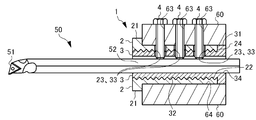
- a gripping tool 1 for gripping a cutting tool and attaching the cutting tool to a cutting machine includes a holding tube (rigid holding tube) 2 made of a substantially cylindrical rigid material, and a substantially cylindrical control.
- a sleeve (damping alloy tube) 3 made of a vibration alloy is coaxially combined.
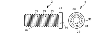
- the holding tube 2 has a flange 21 at one end thereof, the sleeve 3 is inserted from the end opposite to the flange 21, and the side surface of the flange portion 31 provided at one end of the sleeve 3 is held by the holding tube 2. It is made to contact
- the holding tube body 2 is provided with an internal thread on its inner peripheral surface 22 over the entire length along the axis. Further, the holding tube body 2 is provided with a through hole 23 that penetrates from the outer peripheral surface to the inner peripheral surface 22 and attaches a bolt for fixing the cutting tool as will be described later. A plurality of through holes 23 are provided along the axial direction.
- the holding tube body 2 is made of, for example, steel such as S45C, and is a rigid body having a Young's modulus that is at least larger than that of a sleeve 3 to be described later, and typically has a Young's modulus that is twice or more larger than that of the sleeve 3. It is preferable to have.
- the sleeve 3 is provided with a male screw along the axial direction on the outer peripheral surface 32 other than the flange portion 31, and corresponds to the female screw on the inner peripheral surface 22 of the holding tube body 2 described above. It can be screwed.
- the inner peripheral surface of the tubular sleeve 3 defines a mounting hole 34 for inserting and mounting a cutting tool.
- the sleeve 3 is provided with a plurality of through holes 33 penetrating in the radial direction from the outer peripheral surface 32 to the inner peripheral surface so as to correspond to the through holes 23 of the holding tube body 2. That is, each of the through holes 33 is provided at a position that communicates with the through hole 23 when the sleeve 3 is screwed and fixed to the holding tube 2 (see FIG. 1).
- the sleeve 3 is made of a twin-type Mn-based damping alloy, and in terms of mass%, Cu: 16.9 to 27.7%, Ni: 2.1 to 8.2%, Fe: 1.0 to 2. From a Mn—Cu—Ni—Fe based damping alloy having a component composition of 9% and C: 0.05% or less, with the balance being Mn and inevitable impurities (low-content elements such as O and N). Become. Here, the composition range (all are mass%) of each component in this damping alloy is demonstrated. With respect to Cu, if the amount is less than 16.9%, twins are not formed, and if it exceeds 27.7%, segregation increases and sufficient vibration damping characteristics cannot be obtained.
- a more preferable range of the amount of Cu is 19.7 to 25.0%.
- Ni it can improve a damping characteristic by adding as a 3rd element with Mn and Cu which are main elements.
- Mn and Cu which are main elements.
- Fe it can improve a damping characteristic more by adding as Mn, Cu, and Ni as a 4th element.
- the amount of Fe is less than 1.0%, the twin formation cannot be changed, and if it exceeds 2.9%, the contribution to the twin formation is saturated.
- by setting the amount of C to 0.05% or less, even if Mn evaporates and the relative concentration of C increases, deterioration of damping characteristics can be prevented.
- the vibration damping alloy of this embodiment forms twins and absorbs vibrations by converting vibration energy given from the outside into frictional heat at the twin crystal interface.
- a general damping alloy it has a high damping capacity for vibrations in a wide frequency range and can absorb the vibrations efficiently.
- frictional heat is generated at the twin interface even with a smaller stress, and vibration can be efficiently absorbed.
- it has high rigidity and strength compared with a general damping alloy.
- the inner peripheral surface 22 of the holding tube body 2 and the outer peripheral surface 32 of the sleeve 3 are screwed together, and are fixed in a larger area compared to the case where they are fitted with smooth surfaces. is doing.
- the sleeve 3 is made of a surface that is threaded and pressed from the end surface 24 of the holding tube body 2 that is a rigid body having a larger Young's modulus, and is threaded and inclined from the axial direction. A large surface pressure is applied to the outer peripheral surface 32, and the sleeve 3 is firmly fixed to the holding tube 2.
- the above-described gripping tool 1 is inserted into the holding hole 64 of the holder 60 fixed to the cutting machine (not shown) after the grip portion 52 of the rod-shaped cutting tool 50 is inserted into the mounting hole 34. Is done. At this time, the side surface of the flange 21 contacts the holder 60, and the tip 51 of the cutting tool 50 protrudes from the holder 60. In this state, when a bolt hole 63 having a female screw provided in the holder 60 is disposed at a position communicating with the through holes 23 and 33 of the gripping tool 1, and a plurality of bolts 4 are tightened through the bolt holes 63. The tip of the bolt 4 comes into contact with the cutting tool 50.
- the cutting tool 50 is pressed in the direction of travel of the bolt 4, and the outer peripheral surface of the cutting tool 50 opposite to the portion in contact with the bolt 4 is pressed and fixed to the inner peripheral surface of the sleeve 3. Thereby, cutting can be performed while moving the tip 51 relative to the workpiece.
- the sleeve 3 made of a twin-type Mn-based damping alloy is larger than the case where the sleeve 3 is fitted to the inner peripheral surface of the highly rigid holding tube 2 with a smooth inner peripheral surface.
- the area is screwed and fixed.
- the plurality of bolts 4 are tightened, and the outer peripheral surface of the cutting tool 50 opposite to the portion where the bolts 4 are in contact is pressed and fixed to the inner peripheral surface of the sleeve 3. That is, the sleeve 3 fixes the cutting tool 50 while being compressed by being biased and compressed by the holding tube 2 over a wide area in the circumferential direction with a larger area over the entire area in the axial direction due to its rigidity.
- the screw of the sleeve 3 is advanced by being screwed into the holding tube 2 while pressing the side surface of the collar portion 31 of the sleeve 3 against the end surface 24 of the holding tube 2 made of a rigid body having a larger Young's modulus.
- the force in the direction and the force exerted by the flange 31 of the sleeve 3 to counter this are constituted by the outer peripheral surface 32 of the sleeve 3 that is threaded, that is, the threaded surface that is inclined with respect to the axial direction.
- the sleeve 3 can be fixed to the holding tube 2 more firmly. That is, vibration generated in the cutting tool 50 can be absorbed more efficiently.
- the holding tube body 2 made of S45C has, in mass%, Cu: 22.4%, Ni: 5.2%, Fe: 2.0%, C: 0.01%, the balance being Mn and
- This is a cutting tool gripping tool in which a sleeve 3 made of a Mn—Cu—Ni—Fe based damping alloy having a component composition as an unavoidable impurity is screwed (hereinafter referred to as “screw type”).
- the holding tube body 2 has an outer diameter of 40 mm, and an M33 ⁇ 2 female screw is cut over the entire length on the inner peripheral surface.
- the sleeve 3 has an inner diameter of 25.2 mm, and an M33 ⁇ 2 male screw is cut on the outer peripheral surface.
- the total length of the cutting tool gripping tool to which these are screwed and fixed that is, the total length of the sleeve 3 is 96 mm.
- Comparative Example 1 is a cutting tool gripping tool in which the sleeve 3 is not screwed to the holding tube 2 in the first embodiment, but a cylindrical sleeve is cooled and fixed to the holding tube (hereinafter, referred to as “cutting tool gripper”). Referred to as “fitting type”). The boundary diameter is 31 mm, and other dimensions are the same as those in the first embodiment.
- Comparative Example 2 and Comparative Example 3 are cutting tool gripping tools in which a holding tube and a sleeve are integrally formed (hereinafter referred to as “integrated type”).
- the materials of Comparative Example 2 and Comparative Example 3 are S45C used for the holding tube 2 of Example 1 and the Mn—Cu—Ni—Fe based damping alloy used for the sleeve 3 of Example 1, respectively.
- Cutting is performed on a cylindrical workpiece having a length of 200 mm, an outer diameter of 100 mm, and an inner diameter of 62 mm made of SUS304, with a cutting speed of 100 m / min, a cutting amount of 0.5 mm, and a feeding speed of 0.2 mm / rev.
- the boring of the tool with a feed distance of 80 mm was performed in 3 passes with a tool protrusion amount of 140 mm.
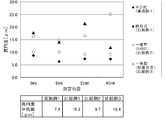
- the roundness was measured using a commercially available three-dimensional measuring device on the inner peripheral surface of the processed hole after performing three passes of boring. The measurement was performed at four locations at a depth of 3 mm, 6 mm, 25 mm, and 45 mm from the end face of the processed hole, and an average value of the measured values at the four locations was recorded for comprehensive evaluation of each example. The average value of each example is shown in the lower part of FIG.
- the roundness is 6.3 to 8.7 ⁇ m
- the average is 7.4 ⁇ m
- the surface roughness Ra is 1.69 to 1. It was 93 ⁇ m.
- the surface roughness Ra was a stable value even when the number of passes was repeated.
- Comparative Example 1 of the “fitting type” the roundness was 11.9 to 21.4 ⁇ m, and the average was 16.3 ⁇ m, which was larger than Example 1. Further, the surface roughness Ra was 2.42 to 5.01 ⁇ m, which was larger than that in Example 1. That is, Example 1 was superior to Comparative Example 1 in processing accuracy evaluated by roundness and surface roughness Ra.
- Example 1 was superior to Comparative Example 2 in processing accuracy evaluated by roundness and surface roughness Ra.
- Comparative Example 2 although the amplitude of vibration generated in the cutting tool is relatively small and the roundness is relatively high, it is considered that the surface roughness becomes rough because the generated vibration cannot be absorbed.
- Example 3 made of a Mn—Cu—Ni—Fe based damping alloy having the same composition as in Example 1, the roundness was 15.0 to 25.3 ⁇ m and the average was 18.4 ⁇ m. It became larger than 1. Further, the surface roughness Ra was 6.54 to 9.19 ⁇ m, which was larger than that of Example 1. That is, Example 1 was superior to Comparative Example 3 in processing accuracy evaluated by roundness and surface roughness Ra.
- the damping alloy is thicker, so twin deformation becomes insufficient, and vibration cannot be efficiently converted into frictional heat, which is good I think that it was not possible to obtain a good vibration control.
- the gripping tool 1 uses a twin-type Mn-based damping alloy that has high rigidity and strength as compared with a general damping alloy, and can efficiently absorb vibrations in a wide frequency range, particularly under a compressive stress.
- the high processing accuracy can be achieved by screwing and fixing the sleeve 3 to the highly rigid holding tube 2.
- a continuous female screw is given to the inner peripheral surfaces of the through hole 23 of the holding tube body 2 and the through hole 33 of the sleeve 3, and a set screw 42 is fastened to the tip so that the tip is cut by the cutting tool 50.
- the cutting tool 50 may be pressed against and fixed to the inner peripheral surface of the sleeve 3.
- the set screw 42 does not protrude from the outer peripheral surface of the holding tube 2 and does not contact the holder 60.
- the holding tube body 2 is pressed and fixed to the holder 60 with a bolt (not shown). It can reduce that the set screw 42 does not contact the holder 60 and the vibration generated in the cutting tool 50 is transmitted to the outside of the cutting tool gripping tool 1.
- a shorter set screw 42 may be used so as not to protrude from the outer peripheral surface of the sleeve 3. That is, by preventing the set screw 42 from contacting not only the holder 60 but also the holding tube 2, vibration generated in the cutting tool 50 can be prevented from being transmitted outside without passing through the sleeve 3.
- the cutting tool gripping tool of the present invention excellent processing accuracy can be provided in the cutting process in which the cutting tool is attached to the cutting tool gripping tool.
Landscapes
- Engineering & Computer Science (AREA)
- Mechanical Engineering (AREA)
- Cutting Tools, Boring Holders, And Turrets (AREA)
- Auxiliary Devices For Machine Tools (AREA)
Priority Applications (4)
| Application Number | Priority Date | Filing Date | Title |
|---|---|---|---|
| SE1451635A SE538022C2 (sv) | 2012-06-29 | 2013-06-21 | Cutting tool gripping tool |
| CN201380034662.4A CN104640656A (zh) | 2012-06-29 | 2013-06-21 | 切削工具夹具 |
| KR20147036476A KR20150040812A (ko) | 2012-06-29 | 2013-06-21 | 절삭 공구 파지구 |
| IN11026DEN2014 IN2014DN11026A (th) | 2012-06-29 | 2013-06-21 |
Applications Claiming Priority (2)
| Application Number | Priority Date | Filing Date | Title |
|---|---|---|---|
| JP2012-146856 | 2012-06-29 | ||
| JP2012146856A JP5805019B2 (ja) | 2012-06-29 | 2012-06-29 | 切削工具把持具 |
Publications (1)
| Publication Number | Publication Date |
|---|---|
| WO2014002905A1 true WO2014002905A1 (ja) | 2014-01-03 |
Family
ID=49783057
Family Applications (1)
| Application Number | Title | Priority Date | Filing Date |
|---|---|---|---|
| PCT/JP2013/067119 Ceased WO2014002905A1 (ja) | 2012-06-29 | 2013-06-21 | 切削工具把持具 |
Country Status (6)
| Country | Link |
|---|---|
| JP (1) | JP5805019B2 (th) |
| KR (1) | KR20150040812A (th) |
| CN (1) | CN104640656A (th) |
| IN (1) | IN2014DN11026A (th) |
| SE (1) | SE538022C2 (th) |
| WO (1) | WO2014002905A1 (th) |
Cited By (2)
| Publication number | Priority date | Publication date | Assignee | Title |
|---|---|---|---|---|
| US20160121407A1 (en) * | 2014-10-29 | 2016-05-05 | National Institute of Technology | Inner sleeve for taper collet and cutting tool holder |
| US10010943B2 (en) | 2012-10-04 | 2018-07-03 | Korea Institute Of Machinery & Materials | Apparatus and method for attenuation of vibration in machine tool |
Families Citing this family (7)
| Publication number | Priority date | Publication date | Assignee | Title |
|---|---|---|---|---|
| KR101693839B1 (ko) * | 2015-01-05 | 2017-01-06 | 두산중공업 주식회사 | 강(steel)으로 이루어진 보강대를 포함하여 열변형 방지 기능이 개선된 보링 헤드 |
| JP6352850B2 (ja) * | 2015-04-10 | 2018-07-04 | 株式会社新興鉄工所 | ツール位置決め治具 |
| US9993876B2 (en) * | 2015-12-21 | 2018-06-12 | Iscar, Ltd. | Cutting tool holder with vibration damping weight assembly |
| CN108747558B (zh) * | 2018-05-28 | 2019-05-07 | 西北工业大学 | 一种柱形零件铣削抑振实现装置及其铣削抑振方法 |
| JP7561693B2 (ja) * | 2021-06-14 | 2024-10-04 | オークマ株式会社 | 工具ホルダ及び工作機械 |
| JP7702859B2 (ja) * | 2021-11-29 | 2025-07-04 | オークマ株式会社 | 工具ホルダ及び工作機械 |
| JP7692062B2 (ja) * | 2022-01-05 | 2025-06-12 | 京セラ株式会社 | 切削インサート、切削工具、及び切削加工物の製造方法 |
Citations (4)
| Publication number | Priority date | Publication date | Assignee | Title |
|---|---|---|---|---|
| JPS4928984A (th) * | 1972-07-13 | 1974-03-14 | ||
| JPS63191506A (ja) * | 1987-02-04 | 1988-08-09 | Nippon Denso Co Ltd | 工作機械の刃物ホルダ− |
| JPH0570808U (ja) * | 1991-02-01 | 1993-09-24 | 三菱マテリアル株式会社 | ボーリングバーの装着構造 |
| JPH0768403A (ja) * | 1993-06-25 | 1995-03-14 | Takamatsu Kikai Kogyo Kk | 工作機械の刃物台 |
Family Cites Families (3)
| Publication number | Priority date | Publication date | Assignee | Title |
|---|---|---|---|---|
| SE528470C2 (sv) * | 2004-02-03 | 2006-11-21 | Mircona Ab | Vibrationsdämpad verktygshållare med viskoelastiskt dämpningsmaterial |
| SE532721C2 (sv) * | 2007-10-01 | 2010-03-23 | Mircona Ab | Produkt med vibrationsdämpande keramisk beläggning för spånavskiljning vid materialbearbetning samt metod för dess tillverkning |
| JP3153247U (ja) * | 2009-06-17 | 2009-08-27 | 株式会社宮本製作所 | 刃物保持冶具 |
-
2012
- 2012-06-29 JP JP2012146856A patent/JP5805019B2/ja not_active Expired - Fee Related
-
2013
- 2013-06-21 WO PCT/JP2013/067119 patent/WO2014002905A1/ja not_active Ceased
- 2013-06-21 KR KR20147036476A patent/KR20150040812A/ko not_active Withdrawn
- 2013-06-21 IN IN11026DEN2014 patent/IN2014DN11026A/en unknown
- 2013-06-21 SE SE1451635A patent/SE538022C2/sv not_active IP Right Cessation
- 2013-06-21 CN CN201380034662.4A patent/CN104640656A/zh active Pending
Patent Citations (4)
| Publication number | Priority date | Publication date | Assignee | Title |
|---|---|---|---|---|
| JPS4928984A (th) * | 1972-07-13 | 1974-03-14 | ||
| JPS63191506A (ja) * | 1987-02-04 | 1988-08-09 | Nippon Denso Co Ltd | 工作機械の刃物ホルダ− |
| JPH0570808U (ja) * | 1991-02-01 | 1993-09-24 | 三菱マテリアル株式会社 | ボーリングバーの装着構造 |
| JPH0768403A (ja) * | 1993-06-25 | 1995-03-14 | Takamatsu Kikai Kogyo Kk | 工作機械の刃物台 |
Cited By (2)
| Publication number | Priority date | Publication date | Assignee | Title |
|---|---|---|---|---|
| US10010943B2 (en) | 2012-10-04 | 2018-07-03 | Korea Institute Of Machinery & Materials | Apparatus and method for attenuation of vibration in machine tool |
| US20160121407A1 (en) * | 2014-10-29 | 2016-05-05 | National Institute of Technology | Inner sleeve for taper collet and cutting tool holder |
Also Published As
| Publication number | Publication date |
|---|---|
| JP2014008572A (ja) | 2014-01-20 |
| CN104640656A (zh) | 2015-05-20 |
| KR20150040812A (ko) | 2015-04-15 |
| IN2014DN11026A (th) | 2015-09-25 |
| SE538022C2 (sv) | 2016-02-09 |
| SE1451635A1 (sv) | 2014-12-22 |
| SE1451635A2 (th) | 2015-02-24 |
| JP5805019B2 (ja) | 2015-11-04 |
Similar Documents
| Publication | Publication Date | Title |
|---|---|---|
| JP5805019B2 (ja) | 切削工具把持具 | |
| JP2016087708A (ja) | テーパコレット用インナースリーブ及び切削工具ホルダ | |
| JP6324233B2 (ja) | 回転体の防振構造 | |
| JP4993528B2 (ja) | 切削工具 | |
| JPWO2008053638A1 (ja) | コレットチャックの構成部材、コレット及び締付ナット並びにコレットチャック | |
| CN107335821A (zh) | 一种双自由度动力减振镗杆 | |
| CN102139464B (zh) | 一种与待磨削轴的端部适配的堵头 | |
| US20170189971A1 (en) | Vibration Absorption Cutter Holder | |
| JP5976563B2 (ja) | コレット | |
| CN204725193U (zh) | 一种bt刀柄高速切削机构 | |
| US20170312832A1 (en) | Vibration absorption cutter holder | |
| CN109862982B (zh) | 顶端可更换式切削工具的主体部和顶端可更换式切削工具 | |
| CN204912806U (zh) | 一种预应力减振镗刀杆 | |
| JP2004202649A (ja) | 切削工具 | |
| CN111408745A (zh) | 车削加工用加长刀杆的减震方法 | |
| CN205393586U (zh) | 车刀变径套 | |
| JP2001096403A (ja) | 切削工具 | |
| CN209272499U (zh) | 一种可调退让式机夹刀 | |
| KR20220011592A (ko) | 원자력 발전소의 원자력 메인 펌프 장축 슬리브의 압연을 처리하는 방법 | |
| CN105479208A (zh) | 一种用于摩托车减震套筒机加工的快速固定装置 | |
| JP6026827B2 (ja) | 工具ホルダ | |
| JP2016128197A (ja) | 工具ホルダ | |
| CN222856747U (zh) | 一种用于轴齿深孔端面槽加工的偏心转接套及刀具装置 | |
| CN102303138A (zh) | 刀具异型夹持工具 | |
| TWM293103U (en) | Damping tool shank |
Legal Events
| Date | Code | Title | Description |
|---|---|---|---|
| 121 | Ep: the epo has been informed by wipo that ep was designated in this application |
Ref document number: 13808920 Country of ref document: EP Kind code of ref document: A1 |
|
| ENP | Entry into the national phase |
Ref document number: 20147036476 Country of ref document: KR Kind code of ref document: A |
|
| NENP | Non-entry into the national phase |
Ref country code: DE |
|
| 122 | Ep: pct application non-entry in european phase |
Ref document number: 13808920 Country of ref document: EP Kind code of ref document: A1 |