WO2014002944A1 - Système de communication sans fil, dispositif de station de base sans fil, terminal utilisateur et procédé de commande de communication - Google Patents
Système de communication sans fil, dispositif de station de base sans fil, terminal utilisateur et procédé de commande de communication Download PDFInfo
- Publication number
- WO2014002944A1 WO2014002944A1 PCT/JP2013/067238 JP2013067238W WO2014002944A1 WO 2014002944 A1 WO2014002944 A1 WO 2014002944A1 JP 2013067238 W JP2013067238 W JP 2013067238W WO 2014002944 A1 WO2014002944 A1 WO 2014002944A1
- Authority
- WO
- WIPO (PCT)
- Prior art keywords
- rate matching
- cell
- transmission
- base station
- user terminal
- Prior art date
- Legal status (The legal status is an assumption and is not a legal conclusion. Google has not performed a legal analysis and makes no representation as to the accuracy of the status listed.)
- Ceased
Links
Images






Classifications
-
- H—ELECTRICITY
- H04—ELECTRIC COMMUNICATION TECHNIQUE
- H04W—WIRELESS COMMUNICATION NETWORKS
- H04W72/00—Local resource management
- H04W72/12—Wireless traffic scheduling
-
- H—ELECTRICITY
- H04—ELECTRIC COMMUNICATION TECHNIQUE
- H04L—TRANSMISSION OF DIGITAL INFORMATION, e.g. TELEGRAPHIC COMMUNICATION
- H04L51/00—User-to-user messaging in packet-switching networks, transmitted according to store-and-forward or real-time protocols, e.g. e-mail
- H04L51/21—Monitoring or handling of messages
- H04L51/222—Monitoring or handling of messages using geographical location information, e.g. messages transmitted or received in proximity of a certain spot or area
-
- H—ELECTRICITY
- H04—ELECTRIC COMMUNICATION TECHNIQUE
- H04W—WIRELESS COMMUNICATION NETWORKS
- H04W72/00—Local resource management
- H04W72/50—Allocation or scheduling criteria for wireless resources
- H04W72/52—Allocation or scheduling criteria for wireless resources based on load
-
- H—ELECTRICITY
- H04—ELECTRIC COMMUNICATION TECHNIQUE
- H04B—TRANSMISSION
- H04B7/00—Radio transmission systems, i.e. using radiation field
- H04B7/02—Diversity systems; Multi-antenna system, i.e. transmission or reception using multiple antennas
- H04B7/022—Site diversity; Macro-diversity
- H04B7/024—Co-operative use of antennas of several sites, e.g. in co-ordinated multipoint or co-operative multiple-input multiple-output [MIMO] systems
-
- H—ELECTRICITY
- H04—ELECTRIC COMMUNICATION TECHNIQUE
- H04L—TRANSMISSION OF DIGITAL INFORMATION, e.g. TELEGRAPHIC COMMUNICATION
- H04L1/00—Arrangements for detecting or preventing errors in the information received
- H04L1/0001—Systems modifying transmission characteristics according to link quality, e.g. power backoff
- H04L1/0009—Systems modifying transmission characteristics according to link quality, e.g. power backoff by adapting the channel coding
- H04L1/0013—Rate matching, e.g. puncturing or repetition of code symbols
-
- H—ELECTRICITY
- H04—ELECTRIC COMMUNICATION TECHNIQUE
- H04L—TRANSMISSION OF DIGITAL INFORMATION, e.g. TELEGRAPHIC COMMUNICATION
- H04L1/00—Arrangements for detecting or preventing errors in the information received
- H04L1/004—Arrangements for detecting or preventing errors in the information received by using forward error control
- H04L1/0056—Systems characterized by the type of code used
- H04L1/0067—Rate matching
-
- H—ELECTRICITY
- H04—ELECTRIC COMMUNICATION TECHNIQUE
- H04L—TRANSMISSION OF DIGITAL INFORMATION, e.g. TELEGRAPHIC COMMUNICATION
- H04L5/00—Arrangements affording multiple use of the transmission path
- H04L5/003—Arrangements for allocating sub-channels of the transmission path
- H04L5/0032—Distributed allocation, i.e. involving a plurality of allocating devices, each making partial allocation
- H04L5/0035—Resource allocation in a cooperative multipoint environment
-
- H—ELECTRICITY
- H04—ELECTRIC COMMUNICATION TECHNIQUE
- H04L—TRANSMISSION OF DIGITAL INFORMATION, e.g. TELEGRAPHIC COMMUNICATION
- H04L5/00—Arrangements affording multiple use of the transmission path
- H04L5/003—Arrangements for allocating sub-channels of the transmission path
- H04L5/0053—Allocation of signalling, i.e. of overhead other than pilot signals
-
- H—ELECTRICITY
- H04—ELECTRIC COMMUNICATION TECHNIQUE
- H04L—TRANSMISSION OF DIGITAL INFORMATION, e.g. TELEGRAPHIC COMMUNICATION
- H04L5/00—Arrangements affording multiple use of the transmission path
- H04L5/0091—Signalling for the administration of the divided path, e.g. signalling of configuration information
- H04L5/0094—Indication of how sub-channels of the path are allocated
-
- H—ELECTRICITY
- H04—ELECTRIC COMMUNICATION TECHNIQUE
- H04L—TRANSMISSION OF DIGITAL INFORMATION, e.g. TELEGRAPHIC COMMUNICATION
- H04L5/00—Arrangements affording multiple use of the transmission path
- H04L5/0091—Signalling for the administration of the divided path, e.g. signalling of configuration information
- H04L5/0096—Indication of changes in allocation
- H04L5/0098—Signalling of the activation or deactivation of component carriers, subcarriers or frequency bands
-
- H—ELECTRICITY
- H04—ELECTRIC COMMUNICATION TECHNIQUE
- H04L—TRANSMISSION OF DIGITAL INFORMATION, e.g. TELEGRAPHIC COMMUNICATION
- H04L67/00—Network arrangements or protocols for supporting network services or applications
- H04L67/50—Network services
- H04L67/52—Network services specially adapted for the location of the user terminal
-
- H—ELECTRICITY
- H04—ELECTRIC COMMUNICATION TECHNIQUE
- H04L—TRANSMISSION OF DIGITAL INFORMATION, e.g. TELEGRAPHIC COMMUNICATION
- H04L69/00—Network arrangements, protocols or services independent of the application payload and not provided for in the other groups of this subclass
- H04L69/24—Negotiation of communication capabilities
-
- H—ELECTRICITY
- H04—ELECTRIC COMMUNICATION TECHNIQUE
- H04W—WIRELESS COMMUNICATION NETWORKS
- H04W16/00—Network planning, e.g. coverage or traffic planning tools; Network deployment, e.g. resource partitioning or cells structures
- H04W16/24—Cell structures
- H04W16/28—Cell structures using beam steering
-
- H—ELECTRICITY
- H04—ELECTRIC COMMUNICATION TECHNIQUE
- H04W—WIRELESS COMMUNICATION NETWORKS
- H04W72/00—Local resource management
- H04W72/20—Control channels or signalling for resource management
- H04W72/23—Control channels or signalling for resource management in the downlink direction of a wireless link, i.e. towards a terminal
-
- H—ELECTRICITY
- H04—ELECTRIC COMMUNICATION TECHNIQUE
- H04L—TRANSMISSION OF DIGITAL INFORMATION, e.g. TELEGRAPHIC COMMUNICATION
- H04L1/00—Arrangements for detecting or preventing errors in the information received
- H04L2001/0092—Error control systems characterised by the topology of the transmission link
-
- H—ELECTRICITY
- H04—ELECTRIC COMMUNICATION TECHNIQUE
- H04L—TRANSMISSION OF DIGITAL INFORMATION, e.g. TELEGRAPHIC COMMUNICATION
- H04L5/00—Arrangements affording multiple use of the transmission path
- H04L5/003—Arrangements for allocating sub-channels of the transmission path
- H04L5/0058—Allocation criteria
-
- H—ELECTRICITY
- H04—ELECTRIC COMMUNICATION TECHNIQUE
- H04L—TRANSMISSION OF DIGITAL INFORMATION, e.g. TELEGRAPHIC COMMUNICATION
- H04L5/00—Arrangements affording multiple use of the transmission path
- H04L5/003—Arrangements for allocating sub-channels of the transmission path
- H04L5/0078—Timing of allocation
- H04L5/0085—Timing of allocation when channel conditions change
-
- H—ELECTRICITY
- H04—ELECTRIC COMMUNICATION TECHNIQUE
- H04L—TRANSMISSION OF DIGITAL INFORMATION, e.g. TELEGRAPHIC COMMUNICATION
- H04L5/00—Arrangements affording multiple use of the transmission path
- H04L5/003—Arrangements for allocating sub-channels of the transmission path
- H04L5/0078—Timing of allocation
- H04L5/0087—Timing of allocation when data requirements change
-
- H—ELECTRICITY
- H04—ELECTRIC COMMUNICATION TECHNIQUE
- H04L—TRANSMISSION OF DIGITAL INFORMATION, e.g. TELEGRAPHIC COMMUNICATION
- H04L51/00—User-to-user messaging in packet-switching networks, transmitted according to store-and-forward or real-time protocols, e.g. e-mail
- H04L51/04—Real-time or near real-time messaging, e.g. instant messaging [IM]
- H04L51/043—Real-time or near real-time messaging, e.g. instant messaging [IM] using or handling presence information
-
- H—ELECTRICITY
- H04—ELECTRIC COMMUNICATION TECHNIQUE
- H04W—WIRELESS COMMUNICATION NETWORKS
- H04W4/00—Services specially adapted for wireless communication networks; Facilities therefor
- H04W4/02—Services making use of location information
Definitions
- the present invention relates to a radio communication system, a radio base station apparatus, a user terminal, and a communication control method in a next generation mobile communication system.
- HSDPA High Speed Downlink Access Access
- HSUPA High SpeckUsedWedPickUsedWidePac
- CDMA Wideband Code Division Multiple Access
- the third generation system can achieve a maximum transmission rate of about 2 Mbps on the downlink using generally a fixed bandwidth of 5 MHz.
- a transmission rate of about 300 Mbps at the maximum in the downlink and about 75 Mbps at the maximum in the uplink can be realized using a variable band of 1.4 MHz to 20 MHz.
- LTE-A LTE advanced or LTE enhancement
- Inter-cell orthogonalization has been proposed as one of promising technologies for further improving system performance for LTE systems.
- LTE-A orthogonalization within a cell is realized by orthogonal multi-access for both uplink and downlink. That is, in the downlink, the user terminals UE (User Equipment) are orthogonalized in the frequency domain.
- UE User Equipment
- W-CDMA interference randomization is performed between cells by repeating one-cell frequency.
- CoMP coordinated multi-point transmission / reception
- a plurality of cells perform transmission / reception signal processing in cooperation with one or a plurality of user terminals UE.
- Application of such CoMP transmission / reception technology is expected to improve the throughput characteristics of the user terminal UE located particularly at the cell edge.
- joint transmission Joint transmission
- DPS Dynamic Point
- CoMP sets a plurality of cells that perform data transmission in a coordinated manner.
- the user terminal UE that receives the CoMP transmitted data needs to perform rate matching in order to finely adjust the bit rate of the received data.
- rate matching refers to performing an iterative process or a puncturing process on the decoded bits of the transport channel.
- the arrangement (more specifically, the number and position) of the resource elements (RE) to which the physical downlink shared channel (PDSCH: Physical Downlink Shared Channel) is allocated is different. .
- the physical downlink control channel (PDCCH: Physical Downlink Control Channel)
- PDSCH Physical Downlink Control Channel
- a different number of symbols can be set for each cell (the first OFDM symbol to the first 3 OFDM symbols of the subframe). For this reason, the number of REs to which the PDSCH is allocated increases or decreases depending on the number of PDCCH symbols.
- the position of RE set based on cell ID (cell index) changes in CRS (Common Reference Signal). For this reason, the position of the RE to which the PDSCH is allocated changes according to the cell ID of the cells constituting the CoMP set.
- a radio base station apparatus In order to perform rate matching appropriately in the user terminal UE, it is necessary to identify an RE (PDSCH allocation area) to which the PDSCH is allocated for each cell constituting the CoMP set. For this reason, it is preferable that a radio base station apparatus notifies the information (rate matching information) required for rate matching including the information for identifying the allocation area
- the rate matching information changes corresponding to the CoMP form. For this reason, rate matching information to be notified to the user terminal UE is complicated.
- CoMP transmission it is possible to set different CoMP sets for different frequency bands. In this case, the rate matching information to be notified to the user terminal UE becomes more complicated.
- the present invention has been made in view of such circumstances, and even when applying CoMP transmission / reception technology, a radio communication system, a radio base station apparatus, a user terminal, and communication control capable of efficiently signaling information necessary for rate matching It aims to provide a method.
- a radio communication system is a radio communication system including a plurality of radio base station apparatuses each forming a cell and a user terminal connected to each radio base station apparatus via a radio link.
- the radio base station apparatus is required to correspond to the scheduler that schedules CoMP transmission that performs coordinated multipoint transmission to the user terminal as a transmission point together with other radio base station apparatuses, and the transmission mode of CoMP transmission.
- a generation unit Based on a table in which a rate matching pattern is mapped to bit data, a generation unit that generates downlink control information in which the rate matching pattern is incorporated in a physical downlink control channel, and transmits the physical downlink control channel A transmitter for transmitting the physical downlink shared data channel.
- the user terminal receives the physical downlink control channel and receives the physical downlink shared data channel from all the radio base station apparatuses that perform CoMP transmission and the received physical downlink control channel.
- a determination unit that identifies the rate matching pattern incorporated in the included downlink control information based on a table having the same contents as the radio base station device, and the downlink using the identified rate matching pattern And a rate matching unit that performs rate matching of the shared data channel.
- the radio base station apparatus of the present invention is a radio base station apparatus to which a user terminal connects via a radio link, and performs coordinated multipoint transmission to the user terminal as a transmission point together with other radio base station apparatuses.
- Downlink in which the rate matching pattern is incorporated into a physical downlink control channel based on a scheduler that schedules CoMP transmission and a table in which a rate matching pattern necessary for the transmission form of CoMP transmission is mapped to bit data
- a generation unit that generates control information, and a transmission unit that transmits the physical downlink control channel and transmits the physical downlink shared data channel are provided.
- a user terminal is a user terminal that is connected to a plurality of radio base station apparatuses each forming a cell via a radio link, and receives a physical downlink control channel from the radio base station apparatus.
- a receiving unit that receives physical downlink shared data channels from all the radio base station devices that perform CoMP transmission, and a rate matching pattern that is incorporated in downlink control information included in the received physical downlink control channel,
- a determination unit that identifies based on a table prepared in advance; and a rate matching unit that performs rate matching of the downlink shared data channel using the identified rate matching pattern.
- the required rate matching pattern corresponding to the form is bit data Characterized in that it is mapped.
- the communication control method of the present invention is a communication control in a radio communication system comprising a plurality of radio base station apparatuses each forming a cell and a user terminal connected to each radio base station apparatus via a radio link.
- a method for scheduling CoMP transmission in which the plurality of radio base station apparatuses serve as transmission points for the multi-point transmission to the user terminal, and a rate matching necessary for a transmission form of CoMP transmission
- Generating downlink control information in which the rate matching pattern is incorporated in a physical downlink control channel based on a table in which a pattern is mapped to bit data; and transmitting the physical downlink control channel and a physical downlink Transmitting a shared data channel; and
- the rate matching pattern incorporated in the downlink control information The terminal, characterized by comprising a step of identifying, based on said table having the same content as the radio base station apparatus.
- CoMP transmission / reception cooperative multipoint transmission / reception
- rate matching object in case CoMP transmission / reception technique is applied.
- rate matching object in the case of carrying out joint transmission including the cell of MBSFN or New carrier type.
- FIG. 1 is a diagram for explaining a CoMP transmission / reception (cooperative multipoint transmission / reception) technique.
- FIG. 1A is a conceptual diagram of joint transmission (hereinafter referred to as “CoMP transmission (JT)” as appropriate), which is one of CoMP transmissions.
- the same shared data channel (PDSCH) is simultaneously transmitted from a plurality of cells to one user terminal UE in one subframe.
- the user terminal UE receives PDSCH from all transmission cells of cell 0, cell 1 and cell 2 in one subframe.
- the user terminal UE receives the PDSCH jointly transmitted from the cell 0, the cell 1, and the cell 2 based on the PDCCH shared by the cell 0, the cell 1, and the cell 2.
- FIG. 1B is a conceptual diagram of DPS (hereinafter, referred to as “CoMP transmission (DPS)” as appropriate), which is one of CoMP transmissions.
- DPS CoMP transmission
- the transmission cell for one user terminal UE is dynamically switched to transmit the PDSCH.
- the user terminal UE receives the PDSCH transmitted from the cell 0, the cell 1 and the cell 2 based on the PDCCH transmitted from the cell 0, the cell 1 and the cell 2, respectively.
- the radio base station apparatus eNB feeds back quality information of each cell from the user terminal UE. Then, the radio base station apparatus eNB obtains quality information for each cell (for example, RSRP (Reference Signal Received Power), RSRQ (Reference Signal Received Quality), or SINR (Signal Interference Plus) Noise Ratio Ratio).
- RSRP Reference Signal Received Power
- RSRQ Reference Signal Received Quality
- SINR Signal Interference Plus Noise Ratio Ratio
- the radio base station apparatus eNB determines that the user terminal UE exists at the cell edge. In this case, the radio base station apparatus eNB applies CoMP transmission.
- the radio base station apparatus eNB is close to the radio base station apparatus eNB forming any cell. Determines that the user terminal UE exists near the center of a cell with high reception quality. In this case, high reception quality can be maintained without applying CoMP transmission.
- the user terminal UE feeds back channel state information for each of a plurality of cells to the radio base station apparatus eNB (the radio base station apparatus eNB of the serving cell).
- the radio base station apparatus eNB the radio base station apparatus eNB of the serving cell.
- the user terminal UE feeds back channel state information of the serving cell to the radio base station apparatus eNB.
- FIG. 2A shows an example of a frame configuration of a subframe of each cell (cell 0 to cell 2) constituting the CoMP set.
- 2B shows a rate matching target when joint transmission is performed from cell 0 and cell 1 shown in FIG. 2A.
- the horizontal axis indicates time
- the vertical axis indicates frequency. The same applies to FIG.
- the areas to which PDCCH is allocated are different.
- the first OFDM (Orthogonal Frequency Division Multiple Access) symbol is assigned in cell 0
- the first and second OFDM symbols are assigned in cell 1
- the first to third OFDM symbols are assigned in cell 2 as PDCCH allocation regions. It shows about the case where is assigned.
- CRSs are arranged in different REs according to cell IDs.
- the PDSCH is assigned to REs in which the PDCCH and CRS of the subframes of the cell 0 to the cell 2 are not arranged. That is, the PDSCH allocation region is different for each cell constituting the CoMP set.
- the user terminal UE When receiving data from each cell, the user terminal UE performs rate matching for the RE to which the PDSCH is assigned in the subframe of each cell. For example, when receiving data from cell 0, the user terminal UE performs rate matching for REs to which the PDCCH is assigned (RE of the first OFDM symbol) and REs other than the RE to which the CRS is assigned. The same applies when data is received from cell 1 and cell 2.
- a PDSCH that is a rate matching target when joint transmission is performed from the cell 0 and the cell 1 to the user terminal UE will be considered.
- the PDSCH is assigned to an RE to which no PDCCH and CRS are assigned in both the cell 0 and the cell 1.
- the user terminal UE performs rate matching for REs to which the PDCCH is assigned (REs of the first OFDM symbol and the second OFDM symbol) and REs other than the RE to which the CRS is assigned.
- MBMS Multimedia Broadcast Multicast Service
- MBSFN MBMS Single Frequency Network
- a plurality of radio base station apparatuses eNB configuring a network simultaneously transmits the same signal, whereby a user terminal UE transmits a signal transmitted from each radio base station apparatus eNB to RF (Radio Frequency). It is a method that can be synthesized.
- a carrier type that does not have an existing PDCCH allocation area in a subframe is considered as a frame configuration.
- this New carrier type subframe it is assumed that no CRS is allocated and PDSCH is allocated to all REs. Note that this New carrier type subframe can also be referred to as an Additive carrier type subframe.
- FIG. 3 is an explanatory diagram of a rate matching target when joint transmission is performed including an MBSFN or New carrier type cell.
- FIG. 3A shows a frame configuration of the MBSFN subframe.
- FIG. 3B shows a frame structure of a New carrier type subframe.
- FIG. 3C illustrates a PDSCH that is a rate matching target when joint transmission is performed including an MBSFN subframe or a new carrier type cell.
- FIG. 3A shows a case where one OFDM symbol is designated as a PDCCH allocation area.
- an RE other than the PDCCH allocation area is defined as the PDSCH allocation area.
- no CRS is assigned to the PDSCH allocation area. For this reason, in the MBSFN subframe, the PDSCH can be assigned to all REs after the second OFDM symbol or the third OFDM symbol.
- the MBSFN subframe is selectively set to subframes other than subframes # 0, # 4, # 5, and # 9 among subframes # 0 to # 9 constituting the radio frame. That is, the radio base station apparatus eNB can selectively set MBSFN subframes in subframes # 1 to # 3 and # 6 to # 8.
- the PDSCH used as the rate matching object in the case of carrying out joint transmission from this cell 2 and the cell 1 shown in FIG. 2 to the user terminal UE is demonstrated.
- the PDSCH is assigned to an RE to which no PDCCH and CRS are assigned in both the cell 1 and the cell 2.
- the PDCCH and CRS are not allocated to REs after 2 OFDM symbols in the MBSFN subframe and the new carrier type subframe of cell 2. For this reason, the RE to which the PDSCH is assigned in the subframe of cell 1 is the target of rate matching.
- carrier aggregation CA: Carrier Aggregation
- CC Component Carrier
- the PDCCH of one primary cell is different from the PDSCH of a plurality of CCs (one primary cell + maximum four secondary cells).
- Cross-carrier scheduling that performs scheduling is employed.
- the details of the downlink control information transmitted by the PDCCH are defined as a DCI (Downlink Control Information) format.
- the DCI of the secondary cell PDCCH is allocated to the PDCCH allocation region (radio resources from the first OFDM symbol to a maximum of 3 OFDM symbols) in the primary cell.
- CIF Cell Index Field
- a cell index is defined in DCI so that it can be identified which cell is the PDCCH for receiving the PDSCH.
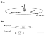
- a case where CA is applied in the system configuration (HetNeT environment) shown in FIG. 4A will be considered.
- a macro cell (cell 0) having a wide coverage area and a pico cell (cell 1) having a local coverage area in the coverage area of the macro cell (cell 0) are arranged.
- the pico cell (cell 1) has a lower transmission power than the macro cell (cell 0), and can also be referred to as a low power cell.
- frequency band 1 is assigned to the macro cell (cell 0)
- frequency band 2 different from frequency band 1 is assigned to the pico cell (cell 1).
- the user terminal UE notifies its own terminal capability (UE Capability) to the radio base station apparatus eNB in the primary cell (Pcell) in order to establish communication (RRC Connection).
- the radio base station apparatus eNB of the primary cell grasps the communication capability of the connected user terminal UE based on the notified terminal capability.
- the radio base station apparatus eNB transmits control information including the following five pieces of information to RRC (Radio Resource Control). Notify by signaling.
- Secondary cell (Scell) index Physical cell ID and downlink carrier frequency CRS port number MBSFN subframe configuration and subframe offset PDSCH start symbol
- PDCCH (DCI) for PDSCH transmitted from each cell Can be transmitted using the PDCCH resource of cell 0 serving as the primary cell.
- FIG. 5C is a conceptual diagram of the DCI format included in the PDCCH, and shows a state in which bit data indicating a cell in CA is described in the CIF. As shown in FIG. 5, 3 bits are allocated to the CIF.
- the user terminal UE when bit information (000) is specified in the CIF included in the DCI of the received PDCCH, the user terminal UE receives the PDSCH of cell 0 as the PDCCH. Can be recognized as a PDCCH.
- bit information (001) when bit information (001) is specified in the CIF included in the DCI of the received PDCCH, the user terminal UE can recognize that the PDCCH is a PDCCH for receiving the PDSCH of the cell 1.
- the radio base station apparatus eNB notifies information required for rate matching (rate matching information).
- rate matching information the notification of rate matching information to the user terminal UE is not defined.
- the present inventors have focused on the fact that rate matching information can be notified to the user terminal UE by using DCI defined in PDCCH even when CoMP transmission / reception technology is applied, and have reached the present invention.
- the gist of the present invention is based on a rate matching table in which a rate matching pattern necessary for the CoMP transmission mode is mapped to bit data in the radio base station apparatus eNB when CoMP transmission / reception technology is applied. , Generating DCI including a rate matching pattern in PDCCH, transmitting this PDCCH and transmitting PDSCH, and setting the rate matching pattern embedded in DCI in user terminal UE to the same content as radio base station apparatus eNB It is specified based on the matching table.
- the PDCCH including DCI incorporating a rate matching pattern corresponding to the CoMP transmission mode is transmitted to the user terminal UE.
- the rate matching pattern incorporated in DCI is specified based on the rate matching table of the same content as the radio base station apparatus eNB. For this reason, even when CoMP transmission / reception technology is applied, it is possible to efficiently signal information necessary for rate matching.
- the user terminal UE establishes its own terminal capability (UE Capability) to the radio base station apparatus eNB in the primary cell (serving cell, cell 0) in order to establish a control channel (RRC Connection). To be notified. Also, the user terminal UE feeds back the generated channel quality information (CQI: Channel Quality Indicator) to the radio base station apparatus eNB.
- UE Capability its own terminal capability
- RRC Connection a control channel
- CQI Channel Quality Indicator
- the radio base station apparatus eNB grasps the communication capability of the connected user terminal UE based on the notified terminal capability.
- the radio base station apparatus eNB notifies the user terminal UE of a measurement candidate cell using a control signal of an RRC (Radio Resource Control) protocol.
- RRC Radio Resource Control
- three cells of cell 0 to cell 2 are notified as measurement candidate cells.
- the user terminal UE measures RSRP and the like of each measurement candidate cell, and reports a measurement report (measurement report) result to the radio base station apparatus eNB by higher layer signaling (for example, RRC signaling).
- the radio base station apparatus eNB determines a CoMP candidate cell from the measurement candidate cells based on the measurement report result.
- this CoMP candidate cell there is a combination of individual cooperative cells that become transmission points (TP) in CoMP transmission (DPS) and multiple cells that become transmission points (TP) in joint transmission (JT) of CoMP.
- the indicated CoMP set is included.
- the radio base station apparatus eNB generates a rate matching table in which the rate matching information corresponding to each cooperative cell (including the serving cell) and the CoMP set in the CoMP candidate cell is associated with the bit information constituting the CIF.
- rate matching information is described as a rate matching pattern.
- the rate matching table is signaled to the user terminal UE by RRC signaling, for example.
- RRC signaling for example.
- a rate matching table is shared between the radio base station apparatus eNB and the user terminal UE.
- the signaling from the radio base station apparatus eNB to the user terminal UE is not limited to RRC signaling.
- MIB Master Information Block
- SIB System Information Block
- MAC Medium Access Control
- FIG. 6 is a diagram illustrating an example of a rate matching table when there are three CoMP candidate cells.
- a rate matching pattern and a CoMP transmission form as rate matching information are registered in association with bit information constituting the CIF.
- a transmission point (TP) for transmitting the PDSCH using an MBSFN subframe or a new carrier type subframe is shown in parentheses.
- the rate matching pattern shown in FIG. 6 (hereinafter, abbreviated as “pattern” as appropriate) will be described with reference to FIGS.
- pattern TP0
- TP1 TP2
- TP2 TP1 and TP2
- the pattern “TP0 & TP1” is a pattern for subjecting the PDSCH allocation area shown in FIG. 2B to rate matching. That is, in both the cell 0 and the cell 1, resources to which PDCCH and CRS are not assigned are targeted for rate matching.
- the pattern “TP0 & TP2” is a pattern in which resources to which no PDCCH and CRS are allocated are targeted for rate matching in both the cell 0 and the cell 2.
- the pattern “TP1 & TP2” is a pattern in which resources to which no PDCCH and CRS are allocated are targeted for rate matching in both the cell 1 and the cell 2.
- the pattern “TP0 & TP1 & TP2” is a pattern in which resources to which no PDCCH and CRS are allocated are targeted for rate matching in any of the cells 0, 1 and 2.
- the pattern “Non-CRS” is a pattern for which the PDSCH allocation area shown in FIG. 3A or FIG. 3B is a rate matching target. That is, in any cell of MBSFN or New carrier type, a resource to which no PDCCH is assigned is a rate matching target.
- the patterns “TP0”, “TP1”, and “TP2” are associated with the bit information (000), (001), and (010) constituting the CIF. Further, the patterns “TP0 & TP1”, “TP0 & TP2” and “TP1 & TP2” are associated with the bit information (011), (100) and (101) constituting the CIF. Further, the patterns “TP0 & TP1 & TP2” and “Non-CRS” are associated with the bit information (110) and (111) constituting the CIF.
- the pattern “TP0” is selected when the PDSCH is transmitted only from the cell 0 (TP0) when CoMP transmission (DPS) is applied.
- the pattern “TP0” is transmitted from the PDSCH from the cell 0 (TP0) and the cell 1 (TP1), and from the cell 1 (TP1) to the MBSFN sub. This is selected when a frame or New carrier type subframe is transmitted.
- the pattern “TP0” is transmitted from the PDSCH from the cell 0 (TP0) and the cell 2 (TP2), and an MBSFN subframe or a new carrier type subframe is transmitted from the cell 2 (TP2). Selected when.
- the pattern “TP0” is transmitted from the PDSCH from the cell 0 (TP0), the cell 1 (TP1), and the cell 2 (TP2), and is transmitted from the cell 1 (TP1) and the cell 2 (TP2) to the MBSFN sub. This is selected when a frame or New carrier type subframe is transmitted. The same applies to the patterns “TP1” and “TP2”.
- the pattern “TP0 & TP1” is selected when transmitting from PDSCH from cell 0 (TP0) and cell 1 (TP1) when CoMP transmission (JT) is applied.
- the pattern “TP0 & TP1” is a case where PDSCH is transmitted from cell 0 (TP0), cell 1 (TP1) and cell 2 (TP2) when CoMP transmission (JT) is applied. This is selected when an MBSFN subframe or a new carrier type subframe is transmitted from (TP2).
- the pattern “TP0 & TP1” is selected when PDSCH is transmitted from cell 0 (TP0) while removing interference due to CRS of cell 1 (TP1). .
- the pattern “TP0 & TP1” is selected when the PDSCH is transmitted from the cell 1 (TP1) while removing the interference due to the CRS of the cell 0 (TP0).
- the pattern “TP0 & TP1 & TP2” is a case where PDSCH is transmitted from the cell 0 (TP0) while removing interference due to CRS of the cell 1 (TP1) and the cell 2 (TP2) when CoMP transmission (DPS) is applied. Selected.
- the pattern “TP0 & TP1 & TP2” is obtained when the PDSCH is transmitted from the cell 1 (TP1) while removing interference due to the CRS of the cell 0 (TP0) and the cell 2 (TP2), or the cell 0 (TP0) and This is selected when PDSCH is transmitted from cell 2 (TP2) while removing interference due to CRS in cell 1 (TP1).
- the pattern “TP0 & TP1 & TP2” is transmitted from the cell 0 (TP0) and the cell 1 (TP1) while removing the interference due to the CRS of the cell 2 (TP2). Is selected.
- the pattern “TP0 & TP1 & TP2” is obtained when the PDSCH is transmitted from the cell 0 (TP0) and the cell 2 (TP2) while removing the interference due to the CRS of the cell 1 (TP1), or in the cell 0 (TP0). This is selected when PDSCH is transmitted from cell 1 (TP1) and cell 2 (TP2) while removing interference due to CRS.
- the pattern “TP0 & TP1 & TP2” is selected when PDSCH is transmitted from the cell 0 (TP0), the cell 1 (TP1), and the cell 2 (TP2) when CoMP transmission (JT) is applied.
- the pattern “Non-CRS” is selected when PDSCH is transmitted in an MBSFN subframe or a new carrier type subframe only from cell 0 (TP0) when CoMP transmission (DPS) is applied. Similarly, the pattern “Non-CRS” is selected when the PDSCH is transmitted from the cell 1 (TP1) or the cell 2 (TP2) only in the MBSFN subframe or the new carrier type subframe. On the other hand, when CoMP transmission (JT) is applied, the pattern “Non-CRS” is transmitted from the cell 0 (TP0) and the cell 1 (TP1) in the MBSFN subframe or the New carrier type subframe. Selected when.
- Non-CRS includes cell 0 (TP0) and cell 2 (TP2), cell 1 (TP1) and cell 2 (TP2), or cell 0 (TP0), cell 1 (TP1) and cell. 2 (TP2) is selected when PDSCH is transmitted in an MBSFN subframe or a new carrier type subframe.
- FIG. 7 is an explanatory diagram of a frame configuration when PDSCH is jointly transmitted from the cell 1 (TP1) and the cell 2 (TP2) while removing interference due to CRS of the cell 0 (TP0). Note that the subframes of cell 0 (TP0) to cell 2 (TP2) shown in FIG. 7 are normal subframes.
- the CRS of cell 0 is the PDSCH assigned to the same RE of the subframe to be jointly transmitted.
- Interference causes signal quality degradation. Therefore, in the rate matching table shown in FIG. 6, the pattern “TP0 & TP1 & TP2” is selected when such a CoMP transmission mode is applied. Thereby, although the capacity of the transmission data is reduced, the deterioration of the signal quality can be suppressed.
- the radio base station apparatus eNB After notifying the user terminal UE of the rate matching table as shown in FIG. 6, the radio base station apparatus eNB performs scheduling based on the CQI fed back from the user terminal UE. In this case, the radio base station apparatus eNB determines a CoMP transmission cell for transmitting the shared data channel to the user terminal UE based on the CQI fed back from the user terminal UE. Along with the determination of the CoMP transmission cell, the CoMP transmission mode is also specified.
- the radio base station apparatus eNB determines whether the determined subframe of the CoMP transmission cell is an MBSFN subframe or a New carrier type subframe. Based on the determination result, the radio base station apparatus eNB selects a rate matching pattern according to the CoMP transmission mode. Then, the radio base station apparatus eNB generates downlink control information (DCI) in which bit information corresponding to the selected rate matching pattern is described in the CIF in the PDCCH of the cell according to the CoMP transmission mode.
- DCI downlink control information
- the user terminal UE recognizes the rate matching table shown in FIG. 6 by notification from the radio base station apparatus eNB.
- the radio base station apparatus eNB performs scheduling based on the CQI fed back from the user terminal UE.
- the radio base station apparatus eNB determines a CoMP transmission cell that transmits a shared data channel to the user terminal UE from the CoMP candidate cells, based on the CQI fed back from the user terminal UE.
- cell 0 (TP0) and cell 1 (TP1) are determined as CoMP transmission cells. That is, joint transmission from cell 0 (TP0) and cell 1 (TP1) is selected.
- the radio base station apparatus eNB determines whether the subframe of the determined CoMP transmission cell (cell 0 and cell 1) is an MBSFN subframe or a new carrier type subframe.
- the subframe of cell 0 (TP0) is an MBSFN subframe. That is, no CRS is assigned in the subframe of cell 0 (TP0).
- the radio base station apparatus eNB selects a rate matching pattern corresponding to the CoMP transmission form, and generates downlink control information (DCI) in which bit information corresponding to the rate matching pattern is described in the CIF.
- DCI downlink control information
- CoMP transmission (JT) is applied to cell 0 (TP0) and cell 1 (TP1), and this corresponds to a CoMP transmission mode in which PDSCH is transmitted from cell 1 (TP1) in an MBSFN subframe.
- the radio base station apparatus eNB selects the pattern “TP1” shown in FIG.
- downlink control information (DCI) in which bit information (001) corresponding to this pattern “TP1” is described in CIF is generated.
- the radio base station apparatus eNB transmits this DCI to the user terminal UE by PDCCH.
- User terminal UE receives PDCCH from radio base station apparatus eNB. Then, the bit information specified in the DCI CIF included in the PDCCH is determined. Here, when it is detected that bit information (001) is specified in the DCI CIF included in the PDCCH, the user terminal UE acquires a pattern “TP1” corresponding to the bit information (001) from the rate matching table. . Then, the user terminal UE performs rate matching on the received data from the radio base station apparatus eNB using the pattern “TP1”.
- a rate matching table in which the rate matching pattern corresponding to the CoMP transmission mode is associated with the bit information constituting the CIF is generated, and the user The terminal UE is notified.
- related with the rate matching pattern corresponding to a CoMP transmission form is selected, and DCI containing the CIF is transmitted to user terminal UE by PDCCH.
- the user terminal UE can identify the rate matching information (rate matching pattern) corresponding to the CoMP transmission form from the CIF defined in the DCI of the PDCCH. For this reason, even when CoMP transmission / reception technology is applied, it is possible to efficiently signal information necessary for rate matching.
- the rate matching table generated by the radio base station apparatus eNB is shared by transmitting it to the user terminal UE, and the PDCCH including the DCI in which the CIF registered in the rate matching table is specified is used. By transmitting, a rate matching pattern corresponding to the CoMP transmission form is signaled.
- a common rate matching table in which a rate matching pattern corresponding to the CoMP transmission mode is registered is held in advance by the radio base station apparatus eNB and the user terminal UE. Then, a rate matching pattern corresponding to the CoMP transmission mode may be signaled by transmitting a PDCCH including DCI in which the CIF registered in the rate matching table is specified.
- CoMP transmission for coordinated multipoint transmission is scheduled for a plurality of radio base station apparatuses eNB as transmission points for the user terminal UE, and a necessary rate matching pattern corresponding to the transmission form of CoMP transmission is converted into bit data.
- a DCI in which the rate matching pattern is incorporated into the PDCCH is generated, the PDCCH is transmitted together with the PDSCH, and the rate matching pattern incorporated into the DCI at the user terminal UE is transmitted to the radio base station apparatus eNB
- the contents specified based on the rate matching table having the same contents are included in the scope of the present invention.
- the rate matching pattern registered in the rate matching table is a pattern that defines a rate matching target based on a resource to which a CRS is assigned.
- the rate matching pattern is not limited to this, and can be changed as appropriate.
- a pattern that defines a rate matching target based on the PDSCH start position can be registered.
- notification of such a rate matching pattern there are a method in accordance with PCFICH (Physical Control Format Indicator Channel) notified in the serving cell, a method of newly adding to DCI, a method of notifying a PDSCH starting symbol by RRC signaling, and the like. Conceivable.
- a rate matching pattern corresponding to the CoMP transmission mode is signaled using CIF used in cross carrier scheduling which is CA technology.
- CIF used in cross carrier scheduling which is CA technology.
- a rate matching attribute notified by higher layer signaling for example, RRC signaling
- the radio base station apparatus eNB notifies the control information containing the following 5 information by RRC signaling.
- Scell Secondary cell index (1-4) -Physical cell ID and downlink carrier frequency-CRS port number-MBSFN subframe configuration and subframe offset-PDSCH start symbol
- the radio base station apparatus eNB By changing a part of the control information, it is possible to notify a rate matching attribute required when rate matching is executed in the CoMP transmission / reception technique.
- the radio base station apparatus eNB notifies control information including the following four pieces of information by RRC signaling.
- the MBSFN subframe configuration and subframe offset are not necessarily required. That is, the MBSFN subframe configuration and the subframe offset do not significantly affect the execution of rate matching.
- the rate matching attribute can be notified to the user terminal UE by changing or deleting a part of the control information notified by RRC signaling at the time of CA execution. . For this reason, it becomes possible to notify a rate matching attribute, without changing significantly the content of RRC signaling notified at the time of CA execution.
- the MBSFN subframe configuration and subframe offset that do not significantly affect the execution of rate matching can be deleted from the control information, the overhead of increasing the ratio of the control signal to the transmission data can be improved.
- the timing for generating the rate matching table is not limited to before scheduling, but may be after scheduling.
- the rate matching table shown in FIG. 6 can be generated after scheduling.
- a scheduling result and a determination result as to whether or not it is an MBSFN subframe (New carrier type subframe) (hereinafter referred to as a determination result of an MBSFN subframe or the like)
- MBSFN subframe New carrier type subframe
- FIG. 8 is a diagram illustrating an example of a rate matching table generated after scheduling.
- the rate matching pattern for rate matching for two or more cells (TP) is omitted from the registration information of the rate matching table shown in FIG. Specifically, the patterns “TP0 & TP1”, “TP0 & TP2”, “TP1 & TP2”, “TP0 & TP1 & TP2” are omitted.
- the rate matching pattern for rate matching for two or more cells (TP) is omitted, the amount of information for notifying the user terminal UE of the rate matching table can be reduced, and the throughput characteristics can be improved.
- a rate matching table limited to a specific CoMP transmission mode can be generated.
- a rate matching table limited to CoMP transmission (DPS) or a rate matching table limited to CoMP transmission (JT) is generated.
- FIG. 9 is a diagram showing an example of a rate matching table limited to CoMP transmission (DPS).
- FIG. 10 is a diagram illustrating an example of a rate matching table limited to CoMP transmission (JT).
- the registration content related to joint transmission is omitted from the registration information of the rate matching table shown in FIG. 6.
- the registration content related to DPS is omitted from the registration information of the rate matching table shown in FIG. 6.
- FIG. 6 shows a rate matching table when there are three CoMP candidate cells.
- the number of CoMP candidate cells is not limited to three, and a rate matching table can be generated based on two CoMP candidate cells.
- FIG. 11 is a diagram illustrating an example of a rate matching table when there are two CoMP candidate cells.
- FIG. 11A an example of the rate matching table produced
- FIG. 11B shows an example of a rate matching table generated after scheduling, similarly to the rate matching table shown in FIG.
- the patterns “TP0” and “TP1” are associated with bit information (000) and (001) constituting the CIF. Further, the patterns “TP0 & TP1” and “Non-CRS” are associated with the bit information (010) and (011) constituting the CIF.
- the pattern “TP0” is selected when the PDSCH is transmitted only from the cell 0 (TP0) when CoMP transmission (DPS) is applied.
- the pattern “TP0” is transmitted from the PDSCH from the cell 0 (TP0) and the cell 1 (TP1), and from the cell 1 (TP1) to the MBSFN sub. This is selected when a frame or New carrier type subframe is transmitted. The same applies to the pattern “TP1”.
- the pattern “TP0 & TP1” is selected when transmitting from PDSCH from cell 0 (TP0) and cell 1 (TP1) when CoMP transmission (JT) is applied. Further, when CoMP transmission (DPS) is applied, the pattern “TP0 & TP1” is selected when PDSCH is transmitted from cell 0 (TP0) while removing interference due to CRS of cell 1 (TP1). . On the contrary, the pattern “TP0 & TP1” is selected when the PDSCH is transmitted from the cell 1 (TP1) while removing the interference due to the CRS of the cell 0 (TP0).
- Non-CRS is when the PDSCH is transmitted in the MBSFN subframe or the new carrier type subframe only from the cell 0 (TP0) or the cell 1 (TP1) when CoMP transmission (DPS) is applied. Selected.
- CoMP transmission (JT) when CoMP transmission (JT) is applied, the pattern “Non-CRS” is transmitted from the cell 0 (TP0) and the cell 1 (TP1) in the MBSFN subframe or the New carrier type subframe. Selected when.
- the rate matching pattern for rate matching for two or more cells (TP) is omitted from the registration information of the rate matching table shown in FIG. 11A. Specifically, the pattern “TP0 & TP1” is omitted.
- the rate matching pattern for rate matching for two or more cells (TP) can be reduced, and the throughput characteristics can be improved.
- FIG. 12A is a diagram illustrating an example of a rate matching table limited to CoMP transmission (DPS).
- FIG. 12B is a diagram illustrating an example of a rate matching table limited to CoMP transmission (JT).
- the registration content related to joint transmission is omitted from the registration information of the rate matching table shown in FIG. 11A.
- the registration content related to DPS is omitted from the registration information of the rate matching table shown in FIG. 11A.
- rate matching information (rate matching pattern) according to the CoMP transmission form is signaled using CIF used in cross carrier scheduling which is CA technology.
- rate matching information is originally signaled using CIF indicating a cell index. For this reason, it is suitable for an environment in which CA is not applied and only CoMP is applied.
- CIF is used for cell index notification and cannot be used for rate matching information signaling. Even in such an environment, it is preferable to efficiently notify the user terminal UE of rate matching information from the viewpoint of improving throughput characteristics and signal quality of the entire system.
- FIG. 13 is a diagram illustrating an example of control information notified by RRC signaling in an environment where CoMP and CA are applied. In FIG. 13, for convenience of explanation, control information notified by RRC signaling in an environment where only CA is applied is shown.
- the control information notified by RRC signaling includes the following information. -Serving cell index (ServCellIndex) ⁇ Secondary cell index (SCellIndex) ⁇ Maximum value of secondary cell (maxSCell) ⁇ Maximum serving cell value (maxServCell)
- the serving cell index is used to identify a serving cell (for example, PCell or SCell), and a numerical value of 0 to 4 is assigned.
- the secondary cell index is used to identify the secondary cell and is assigned a numerical value of 1 to 4.
- a numerical value of 4 is set as the maximum value of the secondary cell
- a numerical value of 5 is set as the maximum value of the serving cell.
- the serving cell index is used to identify a serving cell and a coordination point (for example, a PCell or SCell or a coordination point).
- the numerical value is assigned 0 to 14 (0 to 10) when there are three (two) measurement sizes (measurement candidate cells).
- the secondary cell index is used to identify a secondary cell or coordination point. In the case of three (two) measurement sizes (measurement candidate cells), 1 to 14 (1 to 10) are assigned to the numerical values.
- the maximum value of a secondary cell and a cooperation point is set to the maximum value of a secondary cell.
- 14 (9) is assigned when there are three (two) measurement sizes (measurement candidate cells).
- the maximum value of the serving cell and the maximum value of the coordination point are set as the maximum value of the serving cell.
- 15 (10) is assigned when there are three (two) measurement sizes (measurement candidate cells).
- the serving cell index and the secondary cell index are expanded from 3 bits to 4 bits. This is to enable identification of both the serving cell and the coordination point (for example, PCell or SCell or coordination point). Accordingly, the maximum value of the secondary cell and the maximum value of the serving cell are also changed.
- FIG. 14 is an explanatory diagram of a cell index assigned to a cell in an environment where CoMP and CA are applied.
- FIG. 14 shows a case where a cooperative serving cell (CA serving cell) is arranged in the left column, and CoMP cooperative points are arranged in the center and right columns.
- a value from 0 to 4 is assigned to the cooperative serving cell.
- bit information (0000), (0001), (0010), (0011), and (0100) are assigned.
- numerical values of 5 to 14 are assigned to CoMP coordination points. Specifically, bit information (0101), (0111), (1001), (1011), (1101), (0110), (1000), (1010), (1100), and (1110) are allocated.
- the CC index is set to the same value as the serving cell index indicated by the first 3 bits of the extended CIF described later. In this way, by setting the CC index and the serving index to the same value, the control information used when only CA is applied can be applied without significant changes. Since the first 3 bits of the serving cell index are the same as the CC index, the user terminal UE can grasp the CC index from the serving cell index.
- the coordination serving cell can be grasped by the downlink carrier frequency notified by RRC signaling.
- the downlink carrier frequency is notified from the radio base station apparatus eNB to the user terminal UE (RRC signaling).
- RRC signaling For example, after cell 1 (bit information: 0001) is first added, cell 7 (bit information: 0111) is added. In this case, since both CCs are common CC2, user terminal UE can grasp that cell 1 and cell 7 are the same CoMP cooperation cell set.
- the number of bits constituting the CIF is expanded and set to 6 bits. Note that the number of bits to be expanded is not limited to 3 bits, and can be changed as appropriate. If necessary, the number of bits of 4 bits or more may be expanded, or may be 2 bits or less.
- FIG. 15 is a diagram showing an example of a rate matching table including an extended CIF (hereinafter referred to as “extended CIF”). Note that a part of the table is shown in the rate matching table shown in FIG. Further, in the rate matching table shown in FIG. 15, the registration information of the rate matching pattern and the CoMP transmission form is the same as the rate matching table shown in FIG. Further, in the rate matching table shown in FIG. 15, for convenience of explanation, a hyphen ( ⁇ ) is shown between the bit information of the existing part and the bit information of the extended part of the extended CIF.
- extended CIF extended CIF
- the patterns “TP0”, “TP1” and “TP2” are associated with bit information (000-000), (000-001) and (000-010) constituting the CIF. Yes. Further, the patterns “TP0 & TP1”, “TP0 & TP2”, and “TP1 & TP2” are associated with the bit information (000-011), (000-100), and (000-101) constituting the CIF. Further, the patterns “TP0 & TP1 & TP2” and “Non-CRS” are associated with bit information (000-110) and (000-111) constituting the CIF.
- bit information constituting the extended CIF the first 3 bits indicate a CC index, and the latter 3 bits indicate rate matching information (rate matching pattern).
- bit information (000) corresponding to serving cell 0 is shown.
- bit information (001) is specified in the first three bits of the extended CIF.
- a rate matching table as illustrated in FIG. 15 is generated in the radio base station apparatus eNB. After notifying the user terminal UE of such a rate matching table, the radio base station apparatus eNB transmits a shared data channel to the user terminal UE based on the CQI fed back from the user terminal UE (CoMP transmission). Form).
- the radio base station apparatus eNB determines whether the determined subframe of the CoMP transmission cell is an MBSFN subframe or a New carrier type subframe. Based on the determination result, the radio base station apparatus eNB selects a rate matching pattern according to the CoMP transmission mode. Then, the radio base station apparatus eNB generates downlink control information (DCI) in which bit information corresponding to the selected rate matching pattern is described in the CIF in the PDCCH of the cell according to the CoMP transmission mode.
- DCI downlink control information
- a rate matching table in which the rate matching pattern corresponding to the CoMP transmission form is associated with the bit information configuring the extended CIF is generated in the radio base station apparatus eNB, The user terminal UE is notified. And the extended CIF linked
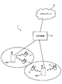
- FIG. 16 is an explanatory diagram of a system configuration of the wireless communication system according to the present embodiment.
- the radio communication system shown in FIG. 16 is a system that includes, for example, the LTE system or SUPER 3G.
- carrier aggregation (CA) in which a plurality of basic frequency blocks having the system band of the LTE system as a unit is integrated is used.
- this wireless communication system may be called IMT-Advanced or 4G.
- the radio communication system 1 includes radio base station devices (hereinafter referred to as “base station devices”) 20A and 20B at each transmission point (TP) and users communicating with the base station devices 20A and 20B.
- a terminal 10 is included.
- the base station devices 20 ⁇ / b> A and 20 ⁇ / b> B are connected to the higher station device 30, and the higher station device 30 is connected to the core network 40.
- the base station devices 20A and 20B are connected to each other by wired connection or wireless connection.
- the user terminal 10 can communicate with the base station apparatuses 20A and 20B that are transmission points.
- the upper station device 30 includes, for example, an access gateway device, a radio network controller (RNC), a mobility management entity (MME), and the like, but is not limited thereto.
- RNC radio network controller
- MME mobility management entity
- the user terminal 10 includes an existing terminal (Rel. 10 LTE) and a support terminal (for example, Rel. 11 LTE).
- a support terminal for example, Rel. 11 LTE.
- the user terminal 10 will be described as a user terminal unless otherwise specified. For convenience of explanation, it is assumed that the user terminal 10 performs wireless communication with the base station apparatuses 20A and 20B.
- OFDMA Orthogonal Frequency Division Multiple Access
- SC-FDMA Single Carrier-Frequency Division Multiple Access
- the wireless access method is not limited to this.
- OFDMA is a multi-carrier transmission scheme that performs communication by dividing a frequency band into a plurality of narrow frequency bands (subcarriers) and mapping data to each subcarrier.
- SC-FDMA is a single carrier transmission method that reduces interference between terminals by dividing a system band into bands each consisting of one or continuous resource blocks for each terminal, and a plurality of terminals using different bands. .
- the downlink communication channel includes PDSCH as a downlink data channel shared by the user terminals 10 and downlink L1 / L2 control channels (PDCCH, PCFICH, PHICH). Transmission data and higher control information are transmitted by the PDSCH. PDSCH and PUSCH scheduling information and the like are transmitted by the PDCCH. The number of OFDM symbols used for the PDCCH is transmitted by PCFICH (Physical Control Format Indicator Channel). HACH ACK / NACK for PUSCH is transmitted by PHICH (Physical Hybrid-ARQ Indicator Channel).
- PCFICH Physical Control Format Indicator Channel
- HACH ACK / NACK for PUSCH is transmitted by PHICH (Physical Hybrid-ARQ Indicator Channel).
- the uplink communication channel has PUSCH (Physical Uplink Shared Channel) as an uplink data channel shared by each user terminal 10 and PUCCH (Physical Uplink Control Channel) as an uplink control channel. Transmission data and higher control information are transmitted by this PUSCH. Also, downlink channel state information (CSI (including CQI and the like)), ACK / NACK, and the like are transmitted by PUCCH.
- PUSCH Physical Uplink Shared Channel
- PUCCH Physical Uplink Control Channel
- the base station apparatus 20 includes a transmission / reception antenna 201, an amplifier unit 202, a transmission / reception unit (notification unit) 203, a baseband signal processing unit 204, a call processing unit 205, and a transmission path interface 206.
- Transmission data transmitted from the base station apparatus 20 to the user terminal 10 via the downlink is input from the higher station apparatus 30 to the baseband signal processing unit 204 via the transmission path interface 206.
- the downlink data channel signal is transmitted from the PDCP layer, RDL layer transmission processing such as transmission data division / combination, RLC (Radio Link Control) retransmission control, MAC (Medium Access), and so on.
- RDL layer transmission processing such as transmission data division / combination, RLC (Radio Link Control) retransmission control, MAC (Medium Access), and so on.
- Control retransmission control, for example, HARQ transmission processing, scheduling, transmission format selection, channel coding, Inverse Fast Fourier Transform (IFFT) processing, and precoding processing are performed.
- transmission processing such as channel coding and inverse fast Fourier transform is performed on the signal of the physical downlink control channel, which is the downlink control channel.
- the baseband signal processing unit 204 notifies the control information for each user terminal 10 to wirelessly communicate with the base station apparatus 20 to the user terminals 10 connected to the same transmission point through the broadcast channel.
- Information for communication at the transmission point includes, for example, system bandwidth in the uplink or downlink, and root sequence identification information (Root) for generating a random access preamble signal in PRACH (Physical Random Access Channel). (Sequence Index).
- the transmission / reception unit 203 converts the baseband signal output from the baseband signal processing unit 204 into a radio frequency band.
- the amplifier unit 202 amplifies the radio frequency signal subjected to frequency conversion and outputs the amplified signal to the transmission / reception antenna 201.
- a radio frequency signal received by the transmission / reception antenna 201 is amplified by the amplifier unit 202 and frequency-converted by the transmission / reception unit 203 to be a baseband signal. And is input to the baseband signal processing unit 204.
- the baseband signal processing unit 204 performs FFT processing, IDFT processing, error correction decoding, MAC retransmission control reception processing, RLC layer, PDCP layer reception processing on transmission data included in the baseband signal received in the uplink I do.
- the decoded signal is transferred to the higher station apparatus 30 via the transmission path interface 206.
- the call processing unit 205 performs call processing such as communication channel setting and release, state management of the base station apparatus 20, and management of radio resources.
- the user terminal 10 includes a transmission / reception antenna 101, an amplifier unit 102, a transmission / reception unit (reception unit) 103, a baseband signal processing unit 104, and an application unit 105.
- a radio frequency signal received by the transmission / reception antenna 101 is amplified by the amplifier unit 102, frequency-converted by the transmission / reception unit 103, and converted into a baseband signal.
- the baseband signal is subjected to FFT processing, error correction decoding, retransmission control reception processing, and the like by the baseband signal processing unit 104.
- downlink transmission data is transferred to the application unit 105.
- the application unit 105 performs processing related to layers higher than the physical layer and the MAC layer. Also, broadcast information in the downlink data is also transferred to the application unit 105.
- uplink transmission data is input from the application unit 105 to the baseband signal processing unit 104.
- the baseband signal processing unit 104 performs mapping processing, retransmission control (HARQ) transmission processing, channel coding, DFT processing, and IFFT processing.
- the transmission / reception unit 103 converts the baseband signal output from the baseband signal processing unit 104 into a radio frequency band. Thereafter, the amplifier unit 102 amplifies the frequency-converted radio frequency signal and transmits it from the transmission / reception antenna 101.
- HARQ retransmission control
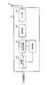
- each functional block in FIG. 19 mainly relates to the baseband signal processing unit 204 shown in FIG. Further, the functional block diagram of FIG. 19 is simplified for explaining the present invention, and is assumed to have a configuration normally provided in the baseband signal processing unit 204.
- the base station apparatus 20 includes a backhaul communication unit 401, a higher control information generation unit 402, a downlink transmission data generation unit 403, a downlink control information generation unit 404, an RS generation unit 405, and a downlink transmission data code.
- the base station apparatus 20 includes a downlink channel multiplexing unit 408, an IFFT unit 409, and a CP adding unit 410.
- the base station apparatus 20 includes a reception unit 411, a terminal capability determination unit 412, a reception quality determination unit 413, a CQI determination unit 414, a CoMP candidate cell determination unit 415, a table generation unit 416, a scheduler 417, It has.
- the backhaul communication unit 401 enables communication with other base stations through the backhaul.
- Upper control information generating section 402 generates higher control information transmitted to the user terminal by higher layer signaling (for example, RRC signaling), and outputs the generated higher control information to downlink transmission data encoding / modulating section 406 To do.
- the upper control information generation unit 402 includes control information including a rate matching attribute necessary for rate matching processing when only CoMP is applied, and information such as a cell index extended when CoMP and CA are applied. The control information including is generated.
- the upper control information generation unit 402 receives a rate matching table generated by a table generation unit 416 described later. Then, upper control information generating section 402 generates higher control information including this rate matching table, and outputs it to downlink transmission data encoding / modulating section 406.
- Downlink transmission data generation section 403 generates downlink transmission data and outputs the downlink transmission data to downlink transmission data encoding / modulation section 406. Note that user data as downlink transmission data is supplied from an upper layer.
- the downlink control information generation unit 404 constitutes a generation unit, and downlink control information (DCI) for controlling PDSCH using a DCI format (for example, DCI format 1A) containing DL ground. Is generated.
- DCI downlink control information
- the downlink control information generation section 404 When only CoMP is applied, the downlink control information generation section 404 generates DCI in which a rate matching pattern according to the CoMP transmission form is described in the CIF based on the registered contents of the rate matching table as shown in FIG. . Further, when CoMP and CA are applied, the downlink control information generation section 404 uses DCI in which a rate matching pattern according to the CoMP transmission form is described in the CIF based on the registered contents of the rate matching table as shown in FIG. Is generated. In this case, the CIF also includes CC index information in CA. At this time, the CIF added to the DCI is instructed by the scheduler 417 based on the registered contents of the rate matching table generated by the table generation unit 416 described later.
- the downlink transmission data coding / modulation section 406 performs channel coding and data modulation on the downlink transmission data and higher control information, and outputs the result to the downlink channel multiplexing section 408.
- the downlink control information coding / modulation section 407 performs channel coding and data modulation on the downlink control information and outputs the result to the downlink channel multiplexing section 408.
- the RS generation unit 405 may generate a desired signal measurement RS and an interference measurement RS in addition to generating an existing reference signal (CRS, CSI-RS, DM-RS). These RSs are output to the downlink channel multiplexing unit 408.
- the downlink channel multiplexing unit 408 generates a transmission signal by combining the downlink control information, the reference signal, the upper control information, and the downlink transmission data.
- the downlink channel multiplexing unit 408 outputs the generated transmission signal to the IFFT unit 409.
- the IFFT unit 409 performs inverse fast Fourier transform (Inverse Fast Fourier Transform) on the transmission signal, and converts the signal in the frequency domain into a signal in the time domain.
- the transmission signal after IFFT is output to CP adding section 410.
- CP adding section 410 adds CP (Cyclic Prefix) to the transmission signal after IFFT, and outputs the transmission signal after CP addition to amplifier section 202 shown in FIG.
- the receiving unit 411 receives a transmission signal from the user terminal, extracts terminal capability information (UE Capability), reception quality information, and channel quality information (CQI) from the received signal, and respectively receives the terminal capability determining unit 412, The data is output to reception quality determination section 413 and CQI determination section 414.
- UE Capability terminal capability information
- CQI channel quality information
- the terminal capability determination unit 412 determines the communication capability of the connected user terminal 10 based on the notified terminal capability of the user terminal 10. In particular, the terminal capability determination unit 412 determines whether the connected user terminal 10 is compatible with CoMP or CA based on the notified terminal capability. The terminal capability determination unit 412 outputs the determined terminal capability of the user terminal 10 to the CoMP candidate cell determination unit 415.
- the reception quality determination unit 413 determines the reception quality (for example, RSRP) of the measurement candidate cell based on the measurement report result.
- Reception quality determination section 413 outputs the determined reception quality to CoMP candidate cell determination section 415.
- the CQI determination unit 414 determines uplink / downlink reception quality.
- the CQI determination unit 414 outputs the determined uplink / downlink reception quality to the scheduler 417.
- the CoMP candidate cell determination unit 415 determines a CoMP candidate cell from the measurement candidate cells based on the terminal capability of the user terminal 10 and the reception quality of the measurement candidate cell.
- the CoMP candidate cell includes a CoMP set indicating a combination of individual coordinated cells serving as transmission points in CoMP transmission (DPS) and a plurality of cells jointly transmitted in CoMP transmission (JT).
- the CoMP candidate cell determination unit 415 outputs the determined CoMP candidate cell to the table generation unit 416.
- the table generation unit 416 generates a rate matching table based on the CoMP candidate cells. In this case, the table generation unit 416 generates the rate matching table shown in FIG. Then, the generated rate matching table is output to the backhaul communication unit 401, the upper control information generation unit 402, and the scheduler 417.
- the scheduler 417 determines a CoMP transmission cell that transmits a shared data channel (PDSCH) to the user terminal 10 from the CoMP candidate cells. At this time, the scheduler 417 also determines the CoMP transmission form. Also, the scheduler 417 determines whether the determined subframe of the CoMP transmission cell is an MBSFN subframe or a new carrier type subframe. For example, whether or not the MBSFN subframe is determined is determined based on the content of another Multi-cell / multicast MBSFN Entity. Based on the determination result and the registration information of the rate matching table, the scheduler 417 selects a rate matching pattern according to the CoMP transmission form. Then, the scheduler 417 instructs the downlink control information generating unit 404 to indicate CIF indicating the rate matching pattern.
- PDSCH shared data channel
- table matching section 416 generates a rate matching table in which the rate matching pattern corresponding to the CoMP transmission mode is associated with the bit information constituting CIF. .
- the generated rate matching table is notified to the user terminal 10 by RRC signaling.
- the scheduler 417 selects the CIF associated with the rate matching pattern corresponding to the CoMP transmission form.
- DCI including the CIF selected by the downlink control information generation unit 404 is generated and transmitted to the user terminal 10 on the downlink.
- the scheduler 417 receives a CoMP candidate cell from the CoMP candidate cell determination unit 415. Then, scheduling is performed from this CoMP candidate cell and CQI. Then, the scheduling result and the like are output to the table generation unit 416.
- the table generation unit 416 generates a rate matching table based on the scheduling result and the like. In this case, the table generation unit 416 generates the rate matching table shown in FIG. Then, the generated rate matching table is output to the backhaul communication unit 401, the upper control information generation unit 402, and the scheduler 417. In this case, since the rate matching table can be generated reflecting the scheduling result, the amount of information in the rate matching table can be reduced. Thereby, the information transmission amount at the time of notifying to the user terminal 10 can be reduced, and the throughput characteristic of the system can be improved.
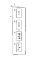
- FIG. 20 mainly relates to the baseband signal processing unit 104 shown in FIG.
- the functional blocks shown in FIG. 20 are simplified to explain the present invention, and the baseband signal processing unit 104 normally has a configuration.
- the user terminal 10 includes a CP removing unit 301, an FFT unit 302, a downlink channel separating unit 303, a downlink control information receiving unit 304, a downlink transmission data receiving unit 305, an interference signal estimating unit 306, A channel estimation unit 307 and a CQI measurement unit 308 are provided.
- the transmission signal transmitted from the base station apparatus 20 is received by the transmission / reception antenna 101 shown in FIG. 18 and output to the CP removal unit 301.
- CP removing section 301 removes the CP from the received signal and outputs it to FFT section 302.
- the FFT unit 302 performs Fast Fourier Transform (FFT) on the signal after CP removal, and converts the signal in the time domain into a signal in the frequency domain.
- FFT section 302 outputs the signal converted into the frequency domain signal to downlink channel separation section 303.
- FFT Fast Fourier Transform
- the downlink channel separation unit 303 separates the downlink channel signal into downlink control information, downlink transmission data, and a reference signal (RS).
- the downlink channel separation unit 303 outputs downlink control information to the downlink control information reception unit 304, outputs downlink transmission data and higher-level control information to the downlink transmission data reception unit 305, and transmits an interference measurement RS to the interference signal estimation unit 306.
- the desired signal measurement RS is output to the channel estimation unit 307.
- the downlink control information receiving unit 304 demodulates the downlink control information (DCI), and outputs the demodulated DCI to the downlink transmission data receiving unit 305.
- Downlink transmission data receiving section 305 demodulates downlink transmission data using the demodulated DCI.
- the downlink control information receiving section 304 analyzes the rate matching pattern incorporated in the DCI CIF included in the PDCCH received from the specific cell using the rate matching table, and calculates the rate matching pattern from the CIF bit information. It functions as a determination unit that identifies The rate matching table is acquired from the upper control information included in the downlink transmission data.
- the downlink transmission data receiving unit 305 functions as a rate matching unit that performs rate matching based on the specified rate matching pattern.
- the downlink transmission data reception unit 305 outputs the upper control information included in the downlink transmission data to the interference signal estimation unit 306 and the channel estimation unit 307.
- the downlink transmission data receiving unit 305 acquires a rate matching table included in the higher control information and refers to it when executing rate matching.
- the interference signal estimation unit 306 estimates an interference signal using downlink reference signals such as CRS and CSI-RS.
- the interference signal estimation unit 306 can estimate the interference signal and average the measurement results in all resource blocks.
- the CQI measurement unit 308 is notified of the averaged interference signal estimation result.
- the channel estimation unit 307 specifies a desired signal measurement RE (CSI-RS resource) based on information such as transmission parameters included in the higher control information (or downlink control information), and uses the desired signal measurement RE to specify the desired signal. presume.
- CSI-RS resource CSI-RS resource
- the channel estimation unit 307 notifies the CQI measurement unit 308 of the channel estimation value.
- CQI measurement section 308 calculates a channel state (CQI) based on the interference estimation result notified from interference signal estimation section 306 and the channel estimation result notified from channel estimation section 307.
- the CQI calculated by the CQI measurement unit 308 is notified to the base station apparatus 20 as feedback information.
- the rate matching pattern corresponding to the CoMP transmission form receives from the base station apparatus 20 the rate matching table associated with the bit information constituting the CIF.
- PDCCH including CIF composed of bit information corresponding to the rate matching pattern is received.
- the user terminal 10 can identify the rate matching information (rate matching pattern) corresponding to the CoMP transmission form from the CIF defined in the DCI of the PDCCH. As a result, even when the CoMP transmission / reception technique is applied, information necessary for rate matching can be efficiently signaled.
Landscapes
- Engineering & Computer Science (AREA)
- Signal Processing (AREA)
- Computer Networks & Wireless Communication (AREA)
- Quality & Reliability (AREA)
- Computer Security & Cryptography (AREA)
- Mobile Radio Communication Systems (AREA)
Abstract
La présente invention permet de signaler efficacement des informations nécessaires à l'adaptation de débit même si une technologie d'émission/réception CoMP est appliquée. Une transmission CoMP consistant en une transmission multipoint coopérative vers un terminal utilisateur (UE) avec une pluralité de dispositifs de station de base sans fil (eNB) comme points de transmission est planifiée ; sur la base d'une table dans laquelle un schéma d'adaptation de débit nécessaire est mis en correspondance avec des données binaires en fonction de la forme de transmission de la transmission CoMP, des informations de commande de liaison descendante comprenant un schéma d'adaptation de débit dans un canal physique de commande sur la liaison descendante sont générées ; le canal physique de commande sur la liaison descendante est transmis au terminal utilisateur (UE) ; et un canal physique de données partagé sur la liaison descendante est transmis ; le schéma d'adaptation de débit contenu dans les informations de commande de liaison descendante au niveau du terminal utilisateur (UE) est identifié sur la base d'une table ayant les mêmes contenus que le dispositif de station de base sans fil (eNB).
Priority Applications (3)
| Application Number | Priority Date | Filing Date | Title |
|---|---|---|---|
| CN201380032318.1A CN104380792A (zh) | 2012-06-26 | 2013-06-24 | 无线通信系统、无线基站装置、用户终端以及通信控制方法 |
| EP13810415.3A EP2866492A4 (fr) | 2012-06-26 | 2013-06-24 | Système de communication sans fil, dispositif de station de base sans fil, terminal utilisateur et procédé de commande de communication |
| US14/410,997 US9426819B2 (en) | 2012-06-26 | 2013-06-24 | Radio communication system, radio base station apparatus, user terminal and communication control method |
Applications Claiming Priority (2)
| Application Number | Priority Date | Filing Date | Title |
|---|---|---|---|
| JP2012-143501 | 2012-06-26 | ||
| JP2012143501A JP2014007670A (ja) | 2012-06-26 | 2012-06-26 | 無線通信システム、無線基地局装置、ユーザ端末及び通信制御方法 |
Publications (1)
| Publication Number | Publication Date |
|---|---|
| WO2014002944A1 true WO2014002944A1 (fr) | 2014-01-03 |
Family
ID=49783090
Family Applications (1)
| Application Number | Title | Priority Date | Filing Date |
|---|---|---|---|
| PCT/JP2013/067238 Ceased WO2014002944A1 (fr) | 2012-06-26 | 2013-06-24 | Système de communication sans fil, dispositif de station de base sans fil, terminal utilisateur et procédé de commande de communication |
Country Status (5)
| Country | Link |
|---|---|
| US (1) | US9426819B2 (fr) |
| EP (1) | EP2866492A4 (fr) |
| JP (1) | JP2014007670A (fr) |
| CN (1) | CN104380792A (fr) |
| WO (1) | WO2014002944A1 (fr) |
Cited By (2)
| Publication number | Priority date | Publication date | Assignee | Title |
|---|---|---|---|---|
| WO2020035954A1 (fr) * | 2018-08-17 | 2020-02-20 | 株式会社Nttドコモ | Équipement d'utilisateur et procédé de communication radio |
| WO2020035953A1 (fr) * | 2018-08-17 | 2020-02-20 | 株式会社Nttドコモ | Équipement utilisateur et procédé de communication radio |
Families Citing this family (23)
| Publication number | Priority date | Publication date | Assignee | Title |
|---|---|---|---|---|
| FI3761740T3 (fi) * | 2012-09-13 | 2023-09-05 | Huawei Tech Co Ltd | Viestintämenetelmä, tukiasema, radioviestintäsolmu ja käyttäjälaite |
| KR102077330B1 (ko) * | 2013-05-23 | 2020-04-02 | 삼성전자 주식회사 | 무선 통신 시스템에서 셀 정보 송수신 방법 및 장치 |
| CN104852778B (zh) * | 2014-02-18 | 2020-03-13 | 中兴通讯股份有限公司 | 一种开销信息传输方法,基站、终端和系统 |
| US9794033B2 (en) * | 2014-03-14 | 2017-10-17 | Intel IP Corporation | Systems, methods and devices for opportunistic networking |
| US9929839B2 (en) * | 2014-08-08 | 2018-03-27 | Futurewei Technologies, Inc. | Device, network, and method for communications with fast adaptive transmission and reception |
| EP3247061B1 (fr) | 2015-01-12 | 2023-03-01 | LG Electronics Inc. | Procédé de fonctionnement d'un équipement utilisateur dans un système de communication sans fil, et dispositif associé |
| US20160242072A1 (en) * | 2015-02-18 | 2016-08-18 | Qualcomm Incorporated | Handling over-sized call setup messages |
| KR102064869B1 (ko) * | 2015-08-14 | 2020-02-11 | 텔레폰악티에볼라겟엘엠에릭슨(펍) | 무선 네트워크에서의 시스템 정보 브로드캐스팅 |
| CN108029102B (zh) * | 2015-09-24 | 2022-04-19 | 株式会社Ntt都科摩 | 终端、无线通信系统及通信方法 |
| CN108353423B (zh) * | 2015-11-10 | 2021-09-28 | 瑞典爱立信有限公司 | 用于管理关于上行链路传送的剩余数据块的上行链路资源的分配的方法和布置 |
| WO2017182071A1 (fr) * | 2016-04-20 | 2017-10-26 | Nokia Solutions And Networks Oy | Détection d'un signal pulsé |
| US10582397B2 (en) * | 2016-11-09 | 2020-03-03 | Qualcomm Incorporated | Beam refinement reference signal transmissions during control symbol |
| KR102164967B1 (ko) * | 2017-01-06 | 2020-10-13 | 한국전자통신연구원 | 통신 시스템에서 제어 채널의 송수신 방법 및 장치 |
| WO2018151533A1 (fr) * | 2017-02-14 | 2018-08-23 | 엘지전자 주식회사 | Procédé de transmission / réception de données dans un système de communication sans fil et appareil correspondant |
| KR102320439B1 (ko) * | 2017-03-08 | 2021-11-03 | 삼성전자 주식회사 | 무선 셀룰라 통신 시스템에서 제어 및 데이터 정보 자원 매핑 방법 및 장치 |
| WO2018164474A1 (fr) * | 2017-03-08 | 2018-09-13 | 삼성전자 주식회사 | Procédé et appareil de commande et mise en correspondance de ressource d'informations de données dans un système de communication cellulaire sans fil |
| CN111555840B (zh) * | 2017-05-05 | 2024-10-15 | 华为技术有限公司 | 一种信息传输的方法及装置 |
| CN109673050B (zh) * | 2017-10-13 | 2022-09-30 | 中国电信股份有限公司 | 数据复用传输方法、网络侧设备及通信系统 |
| US20190313385A1 (en) * | 2018-04-05 | 2019-10-10 | Qualcomm Incorporated | Compact dci for urllc |
| PE20210994A1 (es) * | 2018-07-05 | 2021-06-01 | Ntt Docomo Inc | Terminal y metodo de radiocomunicacion |
| CN112970282B (zh) * | 2018-11-05 | 2024-04-05 | 上海诺基亚贝尔股份有限公司 | 用于harq过程配置的方法、设备和计算机可读介质 |
| KR102932486B1 (ko) * | 2020-03-20 | 2026-02-26 | 삼성전자주식회사 | 협력적 다중-포인트 통신을 위한 무선 통신 시스템 및 이의 동작 방법 |
| EP4231747A4 (fr) * | 2020-10-15 | 2024-07-10 | Ntt Docomo, Inc. | Terminal |
Family Cites Families (2)
| Publication number | Priority date | Publication date | Assignee | Title |
|---|---|---|---|---|
| CN103179075B (zh) * | 2008-11-20 | 2017-06-27 | 华为技术有限公司 | 协作多点传输中确定资源映射的方法、网络设备及系统 |
| CN103999375B (zh) * | 2011-12-16 | 2017-03-08 | Lg电子株式会社 | 针对多小区系统中的物理信道进行资源映射的方法和装置 |
-
2012
- 2012-06-26 JP JP2012143501A patent/JP2014007670A/ja active Pending
-
2013
- 2013-06-24 EP EP13810415.3A patent/EP2866492A4/fr not_active Withdrawn
- 2013-06-24 CN CN201380032318.1A patent/CN104380792A/zh active Pending
- 2013-06-24 US US14/410,997 patent/US9426819B2/en not_active Expired - Fee Related
- 2013-06-24 WO PCT/JP2013/067238 patent/WO2014002944A1/fr not_active Ceased
Non-Patent Citations (6)
| Title |
|---|
| "Feasibility Study for Evolved UTRA and UTRAN", 3GPP, TR25.912 (V7.1.0, September 2006 (2006-09-01) |
| "Transmission mode and DCI content for Release 11", 3GPP TSG-RAN WG1#69, R1-122357, 3GPP, 25 May 2012 (2012-05-25), XP050600620 * |
| HUAWEI ET AL.: "Considerations on DCI for DL CoMP", 3GPP TSG-RAN WG1#68B, RL-120986, 3GPP, 30 March 2012 (2012-03-30), XP050599298 * |
| HUAWEI ET AL.: "Considerations on DL and UL DCI for CoMP", 3GPP TSG-RAN WG1#69, RL-121952, 3GPP, 25 May 2012 (2012-05-25), XP050600253 * |
| LG ELECTRONICS: "Required Downlink Control signaling for CoMP", 3GPP TSG-RAN WG1#68B, RL-121446, 3GPP, 30 March 2012 (2012-03-30), XP050599729 * |
| See also references of EP2866492A4 |
Cited By (7)
| Publication number | Priority date | Publication date | Assignee | Title |
|---|---|---|---|---|
| WO2020035954A1 (fr) * | 2018-08-17 | 2020-02-20 | 株式会社Nttドコモ | Équipement d'utilisateur et procédé de communication radio |
| WO2020035953A1 (fr) * | 2018-08-17 | 2020-02-20 | 株式会社Nttドコモ | Équipement utilisateur et procédé de communication radio |
| JPWO2020035954A1 (ja) * | 2018-08-17 | 2021-08-26 | 株式会社Nttドコモ | ユーザ端末及び無線通信方法 |
| JPWO2020035953A1 (ja) * | 2018-08-17 | 2021-08-26 | 株式会社Nttドコモ | ユーザ端末及び無線通信方法 |
| RU2769721C1 (ru) * | 2018-08-17 | 2022-04-05 | Нтт Докомо, Инк. | Пользовательский терминал и способ радиосвязи |
| JP7248685B2 (ja) | 2018-08-17 | 2023-03-29 | 株式会社Nttドコモ | 端末、無線通信方法、基地局及びシステム |
| JP7264903B2 (ja) | 2018-08-17 | 2023-04-25 | 株式会社Nttドコモ | 端末、無線通信方法、基地局及びシステム |
Also Published As
| Publication number | Publication date |
|---|---|
| US20150341949A1 (en) | 2015-11-26 |
| EP2866492A1 (fr) | 2015-04-29 |
| EP2866492A4 (fr) | 2016-03-16 |
| JP2014007670A (ja) | 2014-01-16 |
| CN104380792A (zh) | 2015-02-25 |
| US9426819B2 (en) | 2016-08-23 |
Similar Documents
| Publication | Publication Date | Title |
|---|---|---|
| US9426819B2 (en) | Radio communication system, radio base station apparatus, user terminal and communication control method | |
| JP5325928B2 (ja) | チャネル状態情報通知方法、無線基地局装置、ユーザ端末及び無線通信システム | |
| CN104380641B (zh) | 无线通信系统、无线基站装置以及无线通信方法 | |
| CN108633078B (zh) | 无线通信方法、无线基站以及用户终端 | |
| US20150110032A1 (en) | Radio communication system, radio base station apparatus, user terminal and communication control method | |
| JP6022775B2 (ja) | 無線通信システム、基地局装置、端末装置及び無線通信制御方法 | |
| JP5785459B2 (ja) | 通信システム、基地局装置、移動端末装置及び通信方法 | |
| JP5612770B2 (ja) | 無線通信システム、無線通信方法、無線基地局装置及びユーザ端末 | |
| WO2014069163A1 (fr) | Procédé de communication sans fil, système de communication sans fil, station de base sans fil, et terminal d'utilisateur | |
| JP2015525031A (ja) | 多地点協調(CoMP)動作とキャリアアグリゲーション(CA)とのジョイントサポートのための技法 | |
| JP2014072694A (ja) | 無線通信システム、無線通信方法、ユーザ端末及び無線基地局 | |
| JP6212188B2 (ja) | 無線通信方法、無線基地局及びユーザ端末 | |
| KR20120135286A (ko) | 무선 네트워크에서의 업링크 협력적 멀티포인트 통신들 | |
| JP5970595B2 (ja) | 無線基地局装置、ユーザ端末及び無線通信方法 | |
| WO2014069164A1 (fr) | Procédé de communication sans fil, système de communication sans fil, station de base sans fil, et terminal d'utilisateur | |
| WO2014021009A1 (fr) | Système de communication sans fil, stations de base sans fil et procédé de commande de retransmission | |
| JP6096253B2 (ja) | ユーザ端末、無線基地局装置、無線通信システムおよび通信制御方法 | |
| WO2014045755A1 (fr) | Système de communication sans fil, terminal d'utilisateur, station de base sans fil, et procédé de communication sans fil | |
| JP2013243751A (ja) | チャネル状態情報通知方法、無線基地局装置、ユーザ端末及び無線通信システム |
Legal Events
| Date | Code | Title | Description |
|---|---|---|---|
| 121 | Ep: the epo has been informed by wipo that ep was designated in this application |
Ref document number: 13810415 Country of ref document: EP Kind code of ref document: A1 |
|
| WWE | Wipo information: entry into national phase |
Ref document number: 14410997 Country of ref document: US |
|
| NENP | Non-entry into the national phase |
Ref country code: DE |
|
| WWE | Wipo information: entry into national phase |
Ref document number: 2013810415 Country of ref document: EP |