WO2014003099A1 - Dispositif de production vidéo - Google Patents
Dispositif de production vidéo Download PDFInfo
- Publication number
- WO2014003099A1 WO2014003099A1 PCT/JP2013/067611 JP2013067611W WO2014003099A1 WO 2014003099 A1 WO2014003099 A1 WO 2014003099A1 JP 2013067611 W JP2013067611 W JP 2013067611W WO 2014003099 A1 WO2014003099 A1 WO 2014003099A1
- Authority
- WO
- WIPO (PCT)
- Prior art keywords
- video
- image
- projected
- sensor camera
- projector
- Prior art date
- Legal status (The legal status is an assumption and is not a legal conclusion. Google has not performed a legal analysis and makes no representation as to the accuracy of the status listed.)
- Ceased
Links
Images


Classifications
-
- G—PHYSICS
- G09—EDUCATION; CRYPTOGRAPHY; DISPLAY; ADVERTISING; SEALS
- G09G—ARRANGEMENTS OR CIRCUITS FOR CONTROL OF INDICATING DEVICES USING STATIC MEANS TO PRESENT VARIABLE INFORMATION
- G09G3/00—Control arrangements or circuits, of interest only in connection with visual indicators other than cathode-ray tubes
- G09G3/001—Control arrangements or circuits, of interest only in connection with visual indicators other than cathode-ray tubes using specific devices not provided for in groups G09G3/02 - G09G3/36, e.g. using an intermediate record carrier such as a film slide; Projection systems; Display of non-alphanumerical information, solely or in combination with alphanumerical information, e.g. digital display on projected diapositive as background
- G09G3/002—Control arrangements or circuits, of interest only in connection with visual indicators other than cathode-ray tubes using specific devices not provided for in groups G09G3/02 - G09G3/36, e.g. using an intermediate record carrier such as a film slide; Projection systems; Display of non-alphanumerical information, solely or in combination with alphanumerical information, e.g. digital display on projected diapositive as background to project the image of a two-dimensional display, such as an array of light emitting or modulating elements or a CRT
-
- G—PHYSICS
- G06—COMPUTING OR CALCULATING; COUNTING
- G06F—ELECTRIC DIGITAL DATA PROCESSING
- G06F3/00—Input arrangements for transferring data to be processed into a form capable of being handled by the computer; Output arrangements for transferring data from processing unit to output unit, e.g. interface arrangements
- G06F3/14—Digital output to display device ; Cooperation and interconnection of the display device with other functional units
- G06F3/1423—Digital output to display device ; Cooperation and interconnection of the display device with other functional units controlling a plurality of local displays, e.g. CRT and flat panel display
Definitions
- the present invention relates to a video production device.
- Patent Document 1 discloses a mechanism that detects a user's instruction and line of sight from an image of a user's appearance and reflects it in information presentation such as an advertisement, but is not intended for video production. Not enough.
- the present invention has been proposed in view of the above-described conventional problems, and an object of the present invention is to provide an interesting video effect capable of capturing various contents.
- the projector and the distance sensor camera arranged at a predetermined position on the viewpoint side of the possible appearance area of the object to be image projected, and the distance sensor camera are obtained.
- a control device that generates an image projected on the surface of the object based on distance information of the surface of the object and outputs a video signal to the projector.
- the video presentation apparatus of the present invention can capture various contents and can perform interesting video presentation.
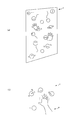
- FIG. (1) which shows the example of a video production.
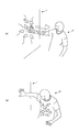
- FIG. (2) which shows the example of a video production.
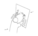
- FIG. 3 which shows the example of a video production.
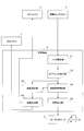
- FIG. 1 is a diagram illustrating a configuration example of a video effect device according to an embodiment of the present invention.
- a large LCD (Liquid Crystal Display) panel 1 is installed on a wall or the like where the player P can approach, and a projector 2 and a distance sensor camera 3 are installed on the ceiling or the like above. It is assumed that the visual field of the distance sensor camera 3 covers an area where an object such as the player P to be detected can appear.
- LCD Liquid Crystal Display
- the LCD panel 1 receives a video signal and displays a video.
- the projector 2 inputs a video signal and projects the video on the surface of an object such as a hand or a body of the player P.
- the distance sensor camera 3 irradiates a fine pattern of infrared light in the direction to be imaged, images an image including the pattern, and analyzes the distance information indicating the distance from the distance sensor camera 3 for each pixel ( A distance video signal having depth information) is output.
- distance information it is good also as what gives an offset to the distance from the distance sensor camera 3, and shows the distance from another position.
- the LCD panel 1, the projector 2, and the distance sensor camera 3 are connected to a control device 4 such as a PC (Personal Computer).
- An audio amplifier 5 for driving the speaker 6 is also connected to the control device 4.
- the display is performed in two systems, that is, the display of the image by the LCD panel 1 and the display (projection) of the image by the projector 2, but the LCD panel 1 is omitted and only the projector 2 is used. You can also.
- the projector 2 and the distance sensor camera 3 are provided above, and this is determined by the relationship between the viewpoint (eye position) of the player P and the target object (here, the hand and body of the player P) to be projected. is there. For example, if an image is projected on the inside of an open umbrella held by the player P, the projector 2 and the distance sensor camera 3 are arranged facing downward.
- FIG. 2 is a diagram illustrating a configuration example of the control device 4.
- the control device 4 includes a noise removal unit 41, an object extraction unit 42, a video / audio production unit 43, a video correction unit 44, a video output unit 45, and an audio output unit 46.
- the noise removing unit 41 has a function of removing noise from the distance video signal output from the distance sensor camera 3.
- the object extraction unit 42 has a function of extracting contour coordinates of an object such as the head, hand, and body of the player P and distance information of each pixel in the contour from the distance video signal after noise removal by the noise removal unit 41. is doing.
- the video / audio production unit 43 has a function of generating video and audio for a predetermined video production according to the state of the object (position, shape, movement, etc. in the three-dimensional space) extracted by the object extraction unit 42. Have.
- the display object displayed on the LCD panel 1 is transferred to the hand or body of the player P. Generate video to be moved.
- the player P's hand moves to a position away from the LCD panel 1, an image for moving the display object that has moved to the player P's hand or body to the LCD panel 1 is generated.
- the player P is in a position where one hand touches the LCD panel 1 and the other hand moves to a position where the other hand touches the LCD panel 1, the display object that has moved to the hand or body of the player P is displayed. Moves to the LCD panel 1 through the other hand, and generates an image that circulates these.
- the video correction unit 44 extracts the head object of the player P from the output of the object extraction unit 42 to specify the viewpoint, and also generates the video generated by the video / audio production unit 43 (video to be output to the projector 2. For the output video, correction is not necessary.)
- the distance information of the surface of the object on which the video is projected is acquired from the output of the object extraction unit 42, and the video viewed from the viewpoint is obtained in a desired shape (for example, by projection mapping). If the image represents a sphere, it has a function of correcting the image so that it becomes a sphere when viewed from the viewpoint.
- the video correcting unit 44 corrects the projected video based on the distance information of the surface of the object to be projected. Furthermore, the image correction unit 44 follows the object surface even if the object surface changes dynamically by acquiring distance information on the object surface at predetermined time intervals (for example, every 1/30 second). The video can be corrected.
- the video output unit 45 has a function of outputting the video corrected by the video correction unit 44 (the video on the LCD panel 1 is not corrected) to the LCD panel 1 and the projector 2.
- the audio output unit 46 has a function of outputting the audio generated by the video / audio production unit 43 to the audio amplifier 5.
- FIG. 3 is a diagram illustrating a configuration example of the video correction unit 44.
- the video correction unit 44 includes a head object extraction unit 441, a viewpoint determination unit 442, a video projection region extraction unit 443, a surface distance information extraction unit 444, and a video projection region video correction unit 445.
- the head object extracting unit 441 has a function of extracting contour coordinates of the head object of the player P (an object estimated from the shape as an object corresponding to the head) and distance information of each pixel in the contour from the output of the object extracting unit 42. have.
- the viewpoint determination unit 442 has a function of determining the three-dimensional coordinates of the viewpoint from the output of the head object extraction unit 441 based on a general head shape and a three-dimensional relative position model of the eyes.
- the video projection area extraction unit 443 has a function of extracting area coordinates where the main projection video exists (for example, area coordinates of the video projected onto the hand of the player P) from the video output from the video / audio production unit 43. .
- the video / audio production unit 43 outputs the region coordinates where the main projection video exists separately, the video projection region extraction unit 443 is omitted and the video / audio production unit 43 replaces the output of the video projection region extraction unit 443.
- Region coordinate output can be used.
- the surface distance information extraction unit 444 is based on the region coordinates where the main projection image extracted by the image projection region extraction unit 443 exists, the contour coordinates of each object of the object extraction unit 42, and the distance information of each pixel in the contour. It has a function of extracting distance information of the surface of the object of the projection part.
- the video projection area video correction unit 445 converts the video in the contour coordinates extracted by the surface distance information extraction unit 444 from the original video of the video / audio production unit 43 according to the distance information of each pixel in the contour. It has a function of performing a matrix calculation or the like so that the video viewed from the viewpoint determined by the viewpoint determination unit 442 becomes a normal image, and outputs the corrected video signal to the video output unit 45. Yes.
- 4 to 6 are diagrams showing examples of video effects.
- a spherical display object that looks like a mysterious creature or a hand-shaped display object for guiding touching with a hand is displayed. Displayed on the LCD panel 1.
- a spherical display object on the LCD panel 1 is placed around the player P's hand as shown in FIG.
- the projector 2 projects and displays the video that gathers and moves through the hand on the hand of the player P.
- the image projected on the hand of the player P is corrected to be viewed from the viewpoint of the player P, it is possible to realize that the spherical display object comes in real.
- FIG. 5B shows a state in which spherical display objects are gathered on the player P's chest.
- FIG. 6 shows that when the player P touches the LCD panel 1 with the other hand and touches with both hands, the spherical display object moves from one hand of the player P to the other hand through the chest. Returning to the LCD panel 1, it is shown cyclically repeating it.
- the viewpoint determining unit 442 determines a viewpoint serving as a reference for correcting the projected image.
- this viewpoint may be arbitrarily set according to the configuration of the device.
- the viewpoint may be set at a fixed position in advance with respect to the floor or the LCD panel 1, or the viewpoint may be set at infinity on the normal line of each surface of the projection target object.
Landscapes
- Engineering & Computer Science (AREA)
- Theoretical Computer Science (AREA)
- Physics & Mathematics (AREA)
- General Physics & Mathematics (AREA)
- Computer Hardware Design (AREA)
- Human Computer Interaction (AREA)
- General Engineering & Computer Science (AREA)
- Controls And Circuits For Display Device (AREA)
- Digital Computer Display Output (AREA)
- Projection Apparatus (AREA)
Applications Claiming Priority (2)
| Application Number | Priority Date | Filing Date | Title |
|---|---|---|---|
| JP2012148008A JP2014010362A (ja) | 2012-06-29 | 2012-06-29 | 映像演出装置 |
| JP2012-148008 | 2012-06-29 |
Publications (1)
| Publication Number | Publication Date |
|---|---|
| WO2014003099A1 true WO2014003099A1 (fr) | 2014-01-03 |
Family
ID=49783237
Family Applications (1)
| Application Number | Title | Priority Date | Filing Date |
|---|---|---|---|
| PCT/JP2013/067611 Ceased WO2014003099A1 (fr) | 2012-06-29 | 2013-06-27 | Dispositif de production vidéo |
Country Status (2)
| Country | Link |
|---|---|
| JP (1) | JP2014010362A (fr) |
| WO (1) | WO2014003099A1 (fr) |
Cited By (3)
| Publication number | Priority date | Publication date | Assignee | Title |
|---|---|---|---|---|
| WO2015151766A1 (fr) * | 2014-03-31 | 2015-10-08 | コニカミノルタ株式会社 | Système de photographie de projection, dispositif de karaoké, et dispositif de simulation |
| WO2017057426A1 (fr) * | 2015-09-29 | 2017-04-06 | シャープ株式会社 | Dispositif de projection, dispositif de détermination de contenu, procédé de projection, et programme |
| US20180191990A1 (en) * | 2015-09-02 | 2018-07-05 | Bandai Namco Entertainment Inc. | Projection system |
Families Citing this family (4)
| Publication number | Priority date | Publication date | Assignee | Title |
|---|---|---|---|---|
| US9900570B2 (en) | 2014-03-18 | 2018-02-20 | Advanced Healthcare Co., Ltd. | Projector system and calibration board |
| US9943759B2 (en) * | 2014-06-16 | 2018-04-17 | Universal City Studios Llc | Interactive game floor system and method |
| JP7147314B2 (ja) * | 2018-07-19 | 2022-10-05 | セイコーエプソン株式会社 | 表示システム、及び、反射体 |
| JP7669863B2 (ja) | 2021-08-06 | 2025-04-30 | セイコーエプソン株式会社 | 表示方法 |
Citations (3)
| Publication number | Priority date | Publication date | Assignee | Title |
|---|---|---|---|---|
| JPH05249428A (ja) * | 1992-03-05 | 1993-09-28 | Koudo Eizou Gijutsu Kenkyusho:Kk | 投影システム |
| WO2010137496A1 (fr) * | 2009-05-26 | 2010-12-02 | パナソニック電工株式会社 | Dispositif de présentation d'informations |
| JP2011254411A (ja) * | 2010-06-04 | 2011-12-15 | Hokkaido Univ | 映像投影システムおよび映像投影プログラム |
-
2012
- 2012-06-29 JP JP2012148008A patent/JP2014010362A/ja active Pending
-
2013
- 2013-06-27 WO PCT/JP2013/067611 patent/WO2014003099A1/fr not_active Ceased
Patent Citations (3)
| Publication number | Priority date | Publication date | Assignee | Title |
|---|---|---|---|---|
| JPH05249428A (ja) * | 1992-03-05 | 1993-09-28 | Koudo Eizou Gijutsu Kenkyusho:Kk | 投影システム |
| WO2010137496A1 (fr) * | 2009-05-26 | 2010-12-02 | パナソニック電工株式会社 | Dispositif de présentation d'informations |
| JP2011254411A (ja) * | 2010-06-04 | 2011-12-15 | Hokkaido Univ | 映像投影システムおよび映像投影プログラム |
Cited By (4)
| Publication number | Priority date | Publication date | Assignee | Title |
|---|---|---|---|---|
| WO2015151766A1 (fr) * | 2014-03-31 | 2015-10-08 | コニカミノルタ株式会社 | Système de photographie de projection, dispositif de karaoké, et dispositif de simulation |
| US20180191990A1 (en) * | 2015-09-02 | 2018-07-05 | Bandai Namco Entertainment Inc. | Projection system |
| WO2017057426A1 (fr) * | 2015-09-29 | 2017-04-06 | シャープ株式会社 | Dispositif de projection, dispositif de détermination de contenu, procédé de projection, et programme |
| JPWO2017057426A1 (ja) * | 2015-09-29 | 2018-08-30 | シャープ株式会社 | 投影装置、コンテンツ決定装置、投影方法、および、プログラム |
Also Published As
| Publication number | Publication date |
|---|---|
| JP2014010362A (ja) | 2014-01-20 |
Similar Documents
| Publication | Publication Date | Title |
|---|---|---|
| JP7283506B2 (ja) | 情報処理装置、情報処理方法、及び情報処理プログラム | |
| JP6747504B2 (ja) | 情報処理装置、情報処理方法、及びプログラム | |
| US20190371072A1 (en) | Static occluder | |
| US11170521B1 (en) | Position estimation based on eye gaze | |
| US9778815B2 (en) | Three dimensional user interface effects on a display | |
| CN109643145B (zh) | 具有世界传感器和用户传感器的显示系统 | |
| WO2014003099A1 (fr) | Dispositif de production vidéo | |
| JP5877219B2 (ja) | 動き特性を使用することによるディスプレイへの三次元ユーザインターフェイス効果 | |
| US8559677B2 (en) | Image generation system, image generation method, and information storage medium | |
| US8655015B2 (en) | Image generation system, image generation method, and information storage medium | |
| JP6344380B2 (ja) | 画像処理装置および方法、並びにプログラム | |
| US9449394B2 (en) | Image synthesis device, image synthesis system, image synthesis method and program | |
| JP2015114818A (ja) | 情報処理装置、情報処理方法及びプログラム | |
| ES2835598T3 (es) | Interfaz de gesto | |
| JP7073481B2 (ja) | 画像表示システム | |
| JP7367689B2 (ja) | 情報処理装置、情報処理方法、及び記録媒体 | |
| WO2013069360A1 (fr) | Dispositif de traitement d'informations, procédé de commande d'affichage et programme | |
| JP2015153046A (ja) | 画像処理装置、画像処理方法およびプログラム | |
| US20100188355A1 (en) | Apparatus and method for detecting an object pointed by a user | |
| WO2017051570A1 (fr) | Dispositif de traitement d'informations, procédé de traitement d'informations et programme | |
| WO2020003860A1 (fr) | Dispositif de traitement d'informations, procédé de traitement d'informations et programme | |
| JP2018526716A (ja) | 媒介現実 | |
| JP2015084002A (ja) | ミラーディスプレイシステム、及び、その映像表示方法 | |
| KR20160096392A (ko) | 직관적인 상호작용 장치 및 방법 | |
| US20210400234A1 (en) | Information processing apparatus, information processing method, and program |
Legal Events
| Date | Code | Title | Description |
|---|---|---|---|
| 121 | Ep: the epo has been informed by wipo that ep was designated in this application |
Ref document number: 13810744 Country of ref document: EP Kind code of ref document: A1 |
|
| NENP | Non-entry into the national phase |
Ref country code: DE |
|
| 122 | Ep: pct application non-entry in european phase |
Ref document number: 13810744 Country of ref document: EP Kind code of ref document: A1 |