WO2014003103A1 - Instrument d'électrophorèse, dispositif d'électrophorèse, procédé d'introduction d'échantillon et procédé de séparation d'échantillon - Google Patents
Instrument d'électrophorèse, dispositif d'électrophorèse, procédé d'introduction d'échantillon et procédé de séparation d'échantillon Download PDFInfo
- Publication number
- WO2014003103A1 WO2014003103A1 PCT/JP2013/067617 JP2013067617W WO2014003103A1 WO 2014003103 A1 WO2014003103 A1 WO 2014003103A1 JP 2013067617 W JP2013067617 W JP 2013067617W WO 2014003103 A1 WO2014003103 A1 WO 2014003103A1
- Authority
- WO
- WIPO (PCT)
- Prior art keywords
- sample
- separation medium
- electrophoresis
- electrode
- sample separation
- Prior art date
- Legal status (The legal status is an assumption and is not a legal conclusion. Google has not performed a legal analysis and makes no representation as to the accuracy of the status listed.)
- Ceased
Links
Images













Classifications
-
- G—PHYSICS
- G01—MEASURING; TESTING
- G01N—INVESTIGATING OR ANALYSING MATERIALS BY DETERMINING THEIR CHEMICAL OR PHYSICAL PROPERTIES
- G01N27/00—Investigating or analysing materials by the use of electric, electrochemical, or magnetic means
- G01N27/26—Investigating or analysing materials by the use of electric, electrochemical, or magnetic means by investigating electrochemical variables; by using electrolysis or electrophoresis
- G01N27/416—Systems
- G01N27/447—Systems using electrophoresis
- G01N27/44704—Details; Accessories
- G01N27/44743—Introducing samples
-
- G—PHYSICS
- G01—MEASURING; TESTING
- G01N—INVESTIGATING OR ANALYSING MATERIALS BY DETERMINING THEIR CHEMICAL OR PHYSICAL PROPERTIES
- G01N27/00—Investigating or analysing materials by the use of electric, electrochemical, or magnetic means
- G01N27/26—Investigating or analysing materials by the use of electric, electrochemical, or magnetic means by investigating electrochemical variables; by using electrolysis or electrophoresis
- G01N27/416—Systems
- G01N27/447—Systems using electrophoresis
- G01N27/44756—Apparatus specially adapted therefor
Definitions
- the present invention relates to an electrophoresis instrument, an electrophoresis apparatus, a sample introduction method, and a sample separation method that can be suitably applied to two-dimensional electrophoresis of biological samples in life science technology.
- Two-dimensional electrophoresis is generally excellent in the resolution of biological samples such as proteins because of its high resolution.
- isoelectric focusing is used for separation in a one-dimensional direction.
- Isoelectric focusing is a technique in which a voltage is applied to a gel and separation is performed based on the difference in isoelectric points of proteins.
- SDS-polyacrylamide gel electrophoresis SDS-PAGE
- anionic surfactant sodium dodecyl sulfate SDS
- Two-dimensional electrophoresis is widely used for proteomic analysis because it can separate and analyze many proteins at once.
- isoelectric focusing by the above-described cup loading method is performed by firstly urea, thiourea, 3-[(colamidopropyl) dimethylammonio] -1-propanesulfonate (CHAPS), dithiothreitol (DTT), amphoteric
- aqueous solution containing a carrier carrier ampholite
- a dry strip gel IPG gel
- a cover solution such as paraffin oil is added and allowed to stand for several hours to swell (rehydrate) the IPG gel.
- the IPG gel is removed from the above chamber, and the wet filter paper and the electrode are placed on the IPG gel by placing the gel surface upward in the isoelectric focusing chamber. Thereafter, a sample cup is placed at an arbitrary position on the gel, a sample solution containing a biological sample is added to the sample cup, and the cover oil is put in. Cover oil is also put on the gel in the region without the sample cup so that the gel is not exposed to the air, and voltage is applied to start isoelectric focusing.
- a cover solution generally paraffin oil or the like
- the biological sample in the cup is present at a high concentration.
- a filter filter paper or the like
- the trouble of installing such a cover solution, a sample cup, a filter, etc. requires skill for the user, and affects the reproducibility of the separation pattern of electrophoresis by the researcher.
- An object of the present invention is to provide an electrophoresis instrument, an electrophoresis apparatus, a sample introduction method, and a sample separation method capable of easily performing separation of a biological sample by isoelectric focusing with good reproducibility.
- An electrophoresis instrument includes an installation surface on which a sample separation medium that separates a biological sample by electrophoresis, a first electrode and a second electrode connected to both ends of the sample separation medium, , And a recess for injecting a sample solution containing the biological sample is provided on the installation surface of the electrophoresis chamber.
- a sample introduction method is a sample introduction method for introducing the biological sample into a sample separation medium for separating a biological sample by electrophoresis, the installation surface on which the sample separation medium is installed, and the sample
- a sample holding unit that has a first electrode and a second electrode connected to both ends of the separation medium, and holds the sample solution while suppressing wetting and spreading of the sample solution containing the biological sample on the installation surface
- an electrophoresis instrument an electrophoresis apparatus, a sample introduction method, and a sample separation method capable of easily separating a biological sample by isoelectric focusing with good reproducibility.
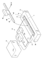
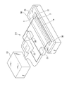
- FIG. 1 is a diagram illustrating a schematic configuration of an electrophoresis apparatus 12 according to the first embodiment.
- FIG. 2 is a diagram illustrating a state in which an IEF (IsoElectric Focusing) chip 40 is installed in the electrophoresis apparatus 12.
- IEF IsoElectric Focusing
- the electrophoresis apparatus 12 includes an electrophoresis instrument 10, a cover 50, a power supply 22, a voltage measuring device 20, a current measuring device 21, a voltage controller 13, and a transport arm 45.
- the electrophoresis instrument 10 includes an electrophoresis chamber 1 for installing the IEF chip 40.
- the electrophoresis chamber 1 is a rectangular groove formed on one surface of the electrophoresis instrument 10, and the bottom surface of the electrophoresis chamber 1 is an installation surface 1 a on which the IEF chip 40 is installed.
- the upper part of the electrophoresis chamber 1 is covered with a cover 50.
- a first electrode 30 connected to the acidic side end of the IEF chip 40 and a second electrode 31 connected to the basic side end of the IEF chip 40 are installed. ing.
- the installation surface 1a of the electrophoresis chamber 1 is provided with a recess 2 for injecting a sample solution containing a biological sample such as protein or nucleic acid.
- the recess 2 is provided between the first electrode 30 and the second electrode 31.
- the first electrode 30 and the second electrode 31 are connected to the power source 22.
- the power source 22 is controlled by the voltage controller 13.
- a normal personal computer can be used as the voltage controller 13.
- the power source 22 is controlled using a development environment such as LabVIEW (Laboratory Virtual Instrument Engineering Lab Workbench).
- the voltage controller 13 transmits a signal for applying a specified voltage to the power source 22.
- the voltage and current supplied from the power source 22 to the first electrode 30 and the second electrode 31 are monitored by the voltage measuring device 20 and the current measuring device 21, respectively.
- the voltage measuring device 21 and the current measuring device 20 detect voltage and current at a frequency of once / 0.1 second or more.
- the IEF chip 40 includes a sample separation medium 42 for one-dimensional electrophoresis and a support 41 that supports the sample separation medium 42.
- the sample separation medium 42 is a medium that separates a biological sample by isoelectric focusing.
- As the sample separation medium 42 one that is usually used as a first-dimensional gel for two-dimensional electrophoresis can be used. Immobilized pH gradient (IPG) gels and the like are suitable.
- As the support 41 for example, a plastic plate or film can be used.
- the sample separation medium 42 may contain a buffer solution.
- the buffer solution is a solution that has a buffering action against the hydrogen ion concentration (a solution in which a small amount of acid or base is added or the pH does not change greatly even if the concentration slightly changes).
- the solution containing it is typical.
- As the buffer it is preferable to use a buffer that does not contain polar molecules. For example, 8M Urea, 2M Thiourea, 4% CHAPS (3-[(3-Cholamidopropyl) dimethylammonio] propanesulfonate), 20 mM dithiothreitol, 0.5
- a buffer solution with a composition of% Ampholyte is preferred.
- the IEF chip 40 is installed in the electrophoresis chamber 1 by the transfer arm 45, and the introduction of a biological sample and the first-dimensional electrophoresis (isoelectric focusing) of the two-dimensional electrophoresis are performed.
- both the introduction of the biological sample and the isoelectric focusing are performed in the electrophoresis chamber 1.
- the introduction of the biological sample is performed in the electrophoresis chamber 1, and the isoelectric focusing is performed elsewhere.
- the electrophoresis chamber third electrophoresis chamber 81 may be used.
- the electrophoresis apparatus 12 is provided with a second electrophoresis chamber 80 for separating biological samples by second-dimensional electrophoresis (SDS-polyacrylamide gel electrophoresis (SDS-PAGE)).
- the IEF chip 40 for which the first-dimensional electrophoresis has been completed is transported to the second electrophoresis chamber 80 by the transport arm 45.
- the second electrophoresis chamber 80 has an installation surface on which the sample separation medium 42 and a polyacrylamide gel which is a second sample separation medium connected to the sample separation medium 42 are installed.
- the second electrophoresis chamber 80 separates the biological sample by applying a voltage to the sample separation medium 42 and the second sample separation medium installed on the installation surface.
- a recess is provided in the installation surface of the portion where the sample separation medium 42 is installed, but in the second electrophoresis chamber, the sample separation medium 42 and the second sample separation medium are There is no depression in the installation surface of the installed part. By flattening the installation surface, a voltage can be stably applied to the sample separation medium 42 and the second sample separation medium.
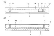
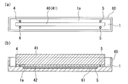
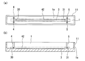
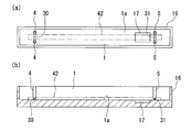
- FIG. 3A is a plan view of the electrophoresis instrument 10
- FIG. 3B is a cross-sectional view of the electrophoresis instrument 10.
- the electrophoresis instrument 10 has a rectangular parallelepiped shape, and an elongated rectangular electrophoresis chamber 1 is formed at the center of the electrophoresis instrument 10.
- a first electrode 30 that is in contact with the acidic side end of the sample separation medium 42 is installed on one end side in the longitudinal direction of the electrophoresis chamber 1, and on the other end side in the longitudinal direction of the electrophoresis chamber 1,
- a second electrode 31 is provided in contact with the basic side end of the sample separation medium 42.
- a first electrode holding part 4 and a second electrode holding part 5 for holding the first electrode 30 and the second electrode 31 are respectively provided on one end side in the longitudinal direction and the other end side in the longitudinal direction of the electrophoresis chamber 1. ing.
- the first electrode holding unit 4 and the second electrode holding unit 5 are provided so as to protrude from the installation surface 1a so as to sandwich the end portion on the acidic side and the end portion on the basic side of the sample separation medium 42, respectively.
- a recess 2 for injecting a sample solution is formed on the bottom surface of the electrophoresis chamber 1 (installation surface 1a on which the IEF chip is installed).
- the recess 2 is arranged so as to be biased toward the acidic side or the basic side with respect to the center of the electrophoresis chamber 1, but the position where the recess 2 is formed is not particularly limited.
- the recess 2 may be formed at the center of the working chamber 1.
- the recess 2 is provided on the side closer to the second electrode 31 than the first electrode 30, but the recess 2 is provided on the side closer to the first electrode 30 than the second electrode 31. Also good.
- the recesses 2 By disposing the recesses 2 on the acidic side or the basic side with respect to the center of the electrophoresis chamber 1, the biological sample travels longer when separating the biological sample by isoelectric focusing, Resolution is improved.
- the volume of the recess 2 is preferably slightly smaller than the volume of the sample solution injected into the recess 2. According to this configuration, when the sample solution is injected into the recess 2, the sample solution rises from the installation surface 1 a, and the sample solution reliably contacts the sample separation medium 42. When the sample solution is small, it is preferable to add a buffer solution to the sample solution so that the depression 2 is filled with the sample solution.
- the area of the recess 2 is not particularly limited as long as it can ensure a sufficient contact area between the sample solution and the sample separation medium 42.
- the width of the depression 2 is larger than the width of the sample separation medium 42, but the width of the depression 2 may be smaller than the width of the sample separation medium 42.
- the width of a part or all of the depression 2 is wider than the width of the sample separation medium 42, the upper part of the depression 2 is not completely covered by the sample separation medium 42, so that the sample separation medium 42 is brought into contact with the sample solution. It is easy to discharge bubbles generated when the sample solution is discharged to the outside of the sample solution.
- the width of a part or the whole of the depression 2 is wider than the width of the sample separation medium 42, it is preferable to cover the upper part of the electrophoresis chamber 1 with a cover 50 in order to prevent the sample solution from drying.
- the entire width of the recess 2 is equal to or smaller than the width of the sample separation medium 42, it is not necessary to cover the upper part of the electrophoresis chamber 1 with the cover 50.
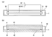
- FIGS. 4 (b) and 5 (b) are cross-sectional views of the electrophoresis instrument.
- the sample introduction method of this embodiment is applied to a sample separation method for separating a biological sample by two-dimensional electrophoresis.
- a voltage is applied between the sample introduction step of introducing a biological sample into the sample separation medium 42 using the sample introduction method of this embodiment and the first electrode 30 and the second electrode 32.
- the first electrophoresis step for separating the biological sample by isoelectric focusing, and the sample separation medium 42 from which the biological sample has been separated by the first electrophoresis step is transferred to the second electrophoresis chamber 80.
- a second electrophoresis step in which a voltage is applied to the sample separation medium 42 transported to the second electrophoresis chamber 80 to separate the biological sample by SDS-polyacrylamide gel electrophoresis (SDS-PAGE). And including.
- the first step of injecting the sample solution S containing the biological sample into the recess 2 of the installation surface 1a where the sample separation medium 42 is installed, and the sample into the sample solution S injected into the recess 2 A second step of contacting the separation medium and introducing a biological sample into the sample separation medium.
- a sample solution S containing a biological sample such as protein or nucleic acid is provided on the installation surface 1a of the electrophoresis chamber 1 to a depth of about 0.5 mm to 1 mm. It inject
- An optimum experimental result can be obtained if the depth of the recess 2 is in a range deeper than 0 mm and shallower than 15 mm, and a more preferable experimental result is obtained if the depth is in the range of 0.5 mm to 1 mm.
- the sample solution S is slightly raised from the installation surface 1a to ensure that the sample solution S comes into contact with the sample separation medium. When the amount of the sample solution S is insufficient, the buffer solution is added to adjust the amount of the sample solution S so that the depression 2 is filled with the sample solution S.
- the IEF chip 40 in which the sample separation medium 42 is saturated and swelled with a buffer solution is placed in the electrophoresis chamber 1 using the transfer arm 45 (see FIG. 2), and the sample solution S
- the hollow 2 that has entered is covered with the sample separation medium 42, and the sample separation medium 42 is brought into close contact with the hollow 2.
- a voltage of about 200 V is applied between the first electrode 30 and the second electrode 31 to introduce a biological sample having a charge into the sample separation medium 42.
- the sample separation medium 42 is pushed into the depression 2 by the transfer arm 45 (see FIG. 2), the voltage is increased to 6000 V, and isoelectric focusing is performed.
- the IEF chip 40 is taken out from the electrophoresis chamber 1 using the transfer arm 45 (see FIG. 2). Then, the sample separation medium 42 is immersed in a solution containing SDS for SDS equilibration, and is connected to a sample separation medium (polyacrylamide gel) for SDS-PAGE. Then, the IEF chip 40 is transferred to the second electrophoresis chamber 80 (see FIG. 2) by the transfer arm 45, and second-dimensional electrophoresis (SDS-PAGE) is performed.
- SDS-PAGE second-dimensional electrophoresis
- the sample solution S is supplied to the electrophoresis chamber 1 and the sample separation medium 42 is placed on the sample solution S to introduce a biological sample. Then, a voltage is applied to the sample separation medium 42 in the electrophoresis chamber 1 as it is to perform isoelectric focusing. Since no anti-drying oil or filter paper for removing impurities is used when the biological sample is introduced into the sample separation medium 42, there is no complicated operation, and highly reproducible data can be obtained.
- the biological sample is introduced while applying a voltage, and after the biological sample is introduced, the dent 2 is filled with the sample separation medium 42 (the inner wall surface and the bottom surface of the dent 2).
- a voltage is applied to the sample separation medium 42 in a state in which the sample separation medium 42 is in close contact therewith. Therefore, the voltage is uniformly applied to the sample separation medium 42, the sample introduction efficiency is high, and uniform focusing and high-resolution separation are performed. Therefore, it is possible to easily separate a biological sample by isoelectric focusing with good reproducibility.
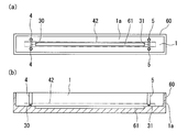
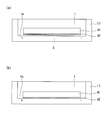
- FIG. 6A is a plan view of the electrophoresis instrument 60 of the second embodiment
- FIG. 6B is a cross-sectional view of the electrophoresis instrument 60.
- the present embodiment is different from the first embodiment in that the depression 61 for injecting the sample solution is located from the side closer to the first electrode 30 to the side closer to the second electrode 31 across the central portion of the electrophoresis chamber 1.
- the elongated separation point and the sample separation medium 42 into which the biological sample has been introduced in the electrophoresis chamber 1 are transported to the third electrophoresis chamber 81 (see FIG. 2), and the third electrophoresis chamber 81 This is the point where isoelectric focusing is performed.
- the length of the recess 61 is slightly shorter than the distance between the first electrode 30 and the second electrode 31.
- the width of the depression 61 is substantially the same as the width of the sample separation medium 42, and the upper portion of the depression 61 is completely covered by the sample separation medium 42.
- the volume of the depression 61 is slightly smaller than the volume of the sample solution injected into the depression 61.
- the third electrophoresis chamber 81 is an electrophoresis chamber having a flat installation surface on which the sample separation medium 42 is installed.
- the third electrophoresis chamber 81 is different from the electrophoresis chamber 1 in that no depression is formed on the installation surface, but the other configuration is the same as the electrophoresis chamber 1. Therefore, the detailed configuration of the third electrophoresis chamber 81 is not shown.
- FIGS. 7 (b) and 8 (b) are cross-sectional views of the electrophoresis instrument.
- a sample solution S containing a biological sample such as protein or nucleic acid is injected into a recess 61 for injecting a sample solution shallower than a depth of 0.5 mm provided on the installation surface 1a of the electrophoresis chamber 1.
- an unsaturated swelling sample separation medium with room for swelling is used as the sample separation medium 42.
- the IEF chip 40 is placed in the electrophoresis chamber 1 using the transfer arm 45 (see FIG. 2), the recess 2 containing the sample solution S is covered with the sample separation medium 42, and the sample separation medium 42 is covered in the recess 2.
- Adhere. As shown in FIG. 8, a voltage of about 200 V is applied between the first electrode 30 and the second electrode 31 to introduce a charged biological sample into the sample separation medium 42.
- the unsaturated swelling sample separation medium 42 is further swollen simultaneously with the introduction of the biological sample, and the sample separation medium 42 reaches the bottom of the recess 61. Therefore, a voltage is uniformly applied to the sample separation medium 42, and the biological sample is efficiently introduced into the sample separation medium 42.
- the sample separation medium 42 is installed in the third electrophoresis chamber 81 (see FIG. 2) using the transfer arm 45 (see FIG. 2). Then, a voltage of 6000 V is applied to the sample separation medium 42 using the first electrode and the second electrode provided in the third electrophoresis chamber 81, and the biological sample is separated by isoelectric focusing.
- the IEF chip 40 is taken out from the third electrophoresis chamber 81 using the transfer arm 45 (see FIG. 2). Then, the sample separation medium 42 is immersed in a solution containing SDS for SDS equilibration, and is connected to a sample separation medium (polyacrylamide gel) for SDS-PAGE. Then, the IEF chip 40 is transferred to the second electrophoresis chamber 80 (see FIG. 2) by the transfer arm 45, and second-dimensional electrophoresis (SDS-PAGE) is performed.
- SDS-PAGE second-dimensional electrophoresis
- the recess 61 is formed elongated in the longitudinal direction of the sample separation medium 42, the biological sample is easily introduced uniformly into the entire sample separation medium 42.
- the isoelectric focusing is performed using the third electrophoresis chamber 81 having a flat installation surface, a uniform voltage is applied to the entire sample separation medium 42 to enable uniform focusing and high-resolution separation. It becomes.
- an unsaturated swelling sample separation medium is used as the sample separation medium 42, but as shown in FIG. 9, a sample separation medium saturated and swollen with a buffer solution is used as the sample separation medium 42. May be.
- the depth of the recess 61 is shallower than the example of FIG.
- a biological sample is introduced into the sample separation medium 42 by applying a voltage of about 200 V to the sample separation medium 42 as shown in FIG.
- the width of the recess 61 for injecting the sample solution may be larger than the width of the sample separation medium 42.
- the width of a part or all of the depression 61 is wider than the width of the sample separation medium 42, the upper part of the depression 61 is not completely covered by the sample separation medium 42, so that the sample separation medium 42 contacts the sample solution. It is easy to discharge bubbles generated when the sample solution is discharged to the outside of the sample solution.
- the width of a part or all of the depression 61 is wider than the width of the sample separation medium 42, it is preferable to cover the upper part of the electrophoresis chamber 1 with a cover in order to prevent the sample solution from drying.
- the entire width of the recess 61 is equal to or smaller than the width of the sample separation medium 42, it is not necessary to cover the upper part of the electrophoresis chamber 1 with a cover.
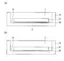
- FIG. 11A is a plan view of the electrophoresis instrument 62 of the third embodiment
- FIG. 11B is a cross-sectional view of the electrophoresis instrument 62.
- the present embodiment is different from the first embodiment in that the width of the central portion of the electrophoresis chamber 70 is reduced to substantially the same width as the sample separation medium 42 to prevent the sample separation medium 42 from drying. is there.
- the electrophoresis chamber 70 has a first portion 71 having a width substantially the same as the width of the sample separation medium 42 and a second portion 72 having a width wider than the width of the sample separation medium 42.
- the first portion 71 has substantially the same length as the distance between the first electrode 30 and the second electrode 31, and the second portion 72 has one end side in the longitudinal direction of the first portion 71 and Connected to the other end.
- the second portion 72 is formed deeper than the first portion 71, and the first electrode 30, the first electrode holding portion 4, the second electrode 31, and the second electrode holding portion 5 are the second portion 72. Is installed.
- the length of the sample separation medium 42 is slightly longer than the length of the first portion 71, and one end side in the longitudinal direction and the other end side in the longitudinal direction of the sample separation medium 42 protrude into the second portion 72.
- the depression 63 for injecting the sample solution is provided on the bottom surface of the first portion 71 (the installation surface 71a of the sample separation medium 42).
- the width of the depression 63 is substantially the same as the width of the sample separation medium 42, and the upper portion of the depression 63 is completely covered by the sample separation medium 42.
- the volume of the recess 63 is slightly smaller than the volume of the sample solution injected into the recess 63.
- the electrophoresis apparatus of this embodiment since the first portion 71 of the electrophoresis chamber 70 has the same width as the sample separation medium 42, the side surface of the sample separation medium 42 is the first portion 71.
- the sample separation medium 42 is prevented from drying. Therefore, it is possible to easily separate the biological sample with high reproducibility.
- the width of the recess 63 for injecting the sample solution may be larger than the width of the sample separation medium 42.
- the width of a part or all of the depression 63 is wider than the width of the sample separation medium 42, the upper part of the depression 63 is not completely covered by the sample separation medium 42, so that the sample separation medium 42 contacts the sample solution. It is easy to discharge bubbles generated when the sample solution is discharged to the outside of the sample solution.
- the recess 63 When a part or all of the recess 63 is wider than the sample separation medium 42, it is preferable to cover the upper part of the electrophoresis chamber 70 with a cover in order to prevent the sample solution from drying. When the entire width of the recess 63 is equal to or smaller than the width of the sample separation medium 42, it is not necessary to cover the upper part of the electrophoresis chamber 70 with a cover.
- electrophoresis chamber 70 has substantially the same width as the sample separation medium 42, but the entire electrophoresis chamber 70 may have substantially the same width as the sample separation medium 42.
- FIG. 12A is a plan view of the electrophoresis instrument 64 of the fourth embodiment
- FIG. 12B is a cross-sectional view of the electrophoresis instrument 64.
- the present embodiment is different from the third embodiment in that a recess 65 for injecting a sample solution is located from the side closer to the first electrode 30 to the side closer to the second electrode 31 across the central portion of the electrophoresis chamber 70. It is the point formed long and thin.
- the recess 65 is provided on the bottom surface of the first portion 71 (installation surface 71a of the sample separation medium 42).
- the length of the recess 65 is slightly shorter than the distance between the first electrode 30 and the second electrode 31.
- the width of the recess 65 is substantially the same as the width of the sample separation medium 42, and the upper portion of the recess 65 is completely covered by the sample separation medium 42.
- the volume of the recess 65 is slightly smaller than the volume of the sample solution injected into the recess 65.
- the recess 65 is formed elongated in the longitudinal direction of the sample separation medium 42, the biological sample is easily introduced uniformly into the entire sample separation medium 42.
- the width of the recess 65 for injecting the sample solution may be larger than the width of the sample separation medium 42.
- the upper part of the recess 65 is not completely covered by the sample separation medium 42, so that the sample separation medium 42 contacts the sample solution. It is easy to discharge bubbles generated when the sample solution is discharged to the outside of the sample solution.
- the width of a part or all of the recess 65 is wider than the width of the sample separation medium 42, it is preferable to cover the upper part of the electrophoresis chamber 70 with a cover in order to prevent the sample solution from drying.
- the entire width of the recess 65 is equal to or smaller than the width of the sample separation medium 42, it is not necessary to cover the upper part of the electrophoresis chamber 70 with a cover.
- FIG. 13A is a plan view of the electrophoresis instrument 66 of the fifth embodiment
- FIG. 13B is a cross-sectional view of the electrophoresis instrument 66.
- This embodiment is different from the fourth embodiment in that a recess 69 for injecting a sample solution is partially widened and exposed to the side of the sample separation medium 42.
- the width of the first portion 71 of the electrophoresis chamber 70 is slightly larger than the width of the sample separation medium 42.
- the recess 69 has a first portion 67 having a width substantially the same as the width of the sample separation medium 42 and a second portion 68 having a width wider than the width of the sample separation medium 42.
- the length of the first portion 67 is slightly shorter than the length of the first portion 71 of the electrophoresis chamber 70, and the second portion 68 has one longitudinal end and the other longitudinal end of the first portion 67. Connected to the side.
- the upper portion of the first portion 67 is completely covered with the sample separation medium 42, but the upper portion of the second portion 68 is not completely covered with the sample separation medium 42. Therefore, it is easy to discharge bubbles generated when the sample separation medium 42 is brought into contact with the sample solution to the outside of the sample solution.
- the rectangular shape and the I shape were illustrated as a shape of the hollow for inject
- the shape of a hollow is not limited to this.
- a depression formed by a curve such as an ellipse or a circle, or a depression having a polygon other than a rectangle may be formed.
- the number of depressions is not limited to one, and a plurality of depressions can be formed.
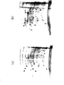
- FIG. 14B is a diagram showing a pattern (example) of two-dimensional electrophoresis performed using the electrophoresis apparatus of the first embodiment.
- FIG. 14A is a diagram showing a two-dimensional electrophoresis pattern (comparative example) when a biological sample is introduced in a conventional gel strip holder. As shown by the arrow spots shown in FIG. 14, the two-dimensional electrophoresis pattern of FIG. 14 (b) has improved resolution compared to the two-dimensional electrophoresis pattern of FIG. 14 (a). A clear spot was detected.
- An electrophoresis instrument includes an installation surface on which a sample separation medium that separates a biological sample by electrophoresis, a first electrode and a second electrode connected to both ends of the sample separation medium, , And a recess for injecting a sample solution containing the biological sample is provided on the installation surface of the electrophoresis chamber.
- the depression is provided on a side closer to the first electrode than the second electrode or a side closer to the second electrode than the first electrode. May be.
- the depression is formed from a side closer to the first electrode to a side closer to the second electrode across the central portion of the electrophoresis chamber. Also good.
- the volume of the depression may be smaller than the volume of the sample solution injected into the depression.
- the sample separation medium may be a swollen gel.
- At least a part of the electrophoresis chamber may be formed to have substantially the same width as the sample separation medium.
- At least a part of the recess may be formed with a width wider than that of the sample separation medium.
- An electrophoresis apparatus includes the electrophoresis instrument of the present invention and a transfer arm that installs the sample separation medium in the electrophoresis chamber.
- the electrophoresis instrument includes a second electrophoresis chamber in which the sample separation medium is placed, and the transfer arm includes the electrophoresis chamber and the second electrophoresis chamber.
- the sample separation medium may be transported between the chambers.
- an electrophoresis instrument includes a flat installation surface on which the sample separation medium is installed, and a first electrode and a second electrode connected to both ends of the sample separation medium.
- a third electrophoresis chamber may be provided, and the transport arm may transport the sample separation medium between the third electrophoresis chamber and the second electrophoresis chamber.
- a sample introduction method is a sample introduction method for introducing the biological sample into a sample separation medium for separating a biological sample by electrophoresis, the installation surface on which the sample separation medium is installed, and the sample Injecting the sample solution containing the biological sample into the depression on the installation surface of the electrophoresis chamber having a first electrode and a second electrode connected to both ends of the separation medium, and a depression provided on the installation surface And a second step of bringing the sample separation medium into contact with the sample solution injected into the depression and introducing the biological sample into the sample separation medium.
- the sample solution in the second step, is brought into contact with the sample separation medium while a voltage is applied between the first electrode and the second electrode. May be.
- a sample separation method includes a sample introduction step of introducing the biological sample into the sample separation medium using the sample introduction method of the present invention, and between the first electrode and the second electrode. Applying a voltage and separating the biological sample by isoelectric focusing.
- the sample separation method includes a transporting step of transporting the sample separation medium from which the biological sample has been separated by the first electrophoresis step to a second electrophoresis chamber; A second electrophoresis step of applying a voltage to the sample separation medium transported to the second electrophoresis chamber and separating the biological sample by SDS-polyacrylamide gel electrophoresis.
- a sample separation method includes a sample introduction step of introducing the biological sample into the sample separation medium using the sample introduction method of the present invention, a flat installation surface on which the sample separation medium is installed, The sample separation medium is placed in a third electrophoresis chamber having a first electrode and a second electrode connected to both ends of the sample separation medium, and the sample separation medium is used for the third electrophoresis A voltage is applied between the first electrode and the second electrode of the third electrophoresis chamber in a state of being in close contact with the installation surface of the chamber, and the biological sample is subjected to isoelectric focusing. Separating the first electrophoresis step.
- the sample separation method includes a transporting step of transporting the sample separation medium from which the biological sample has been separated by the first electrophoresis step to a second electrophoresis chamber; A second electrophoresis step of applying a voltage to the sample separation medium transported to the second electrophoresis chamber and separating the biological sample by SDS-polyacrylamide gel electrophoresis.
- FIG. 15 is a diagram illustrating a schematic configuration of the electrophoresis apparatus 14 according to the sixth embodiment.
- FIG. 16 is a diagram showing a state where an IEF (IsoElectric Focusing) chip 40 is installed in the electrophoresis apparatus 14.
- IEF IsoElectric Focusing
- the electrophoresis device 14 includes an electrophoresis instrument 11, a cover 50, a power supply 22, a voltage measuring device 20, a current measuring device 21, a voltage controller 13, and a transport arm 45.
- the electrophoresis instrument 11 includes an electrophoresis chamber 1 for installing the IEF chip 40.
- the electrophoresis chamber 1 is a rectangular groove formed on one surface of the electrophoresis instrument 11, and the bottom surface of the electrophoresis chamber 1 is an installation surface 1 a on which the IEF chip 40 is installed.
- the upper part of the electrophoresis chamber 1 is covered with a cover 50.
- a first electrode 30 connected to the acidic side end of the IEF chip 40 and a second electrode 31 connected to the basic side end of the IEF chip 40 are installed. ing.
- a sample holder 7 for holding a sample solution containing a biological sample such as protein or nucleic acid.
- the sample holding unit 3 is provided between the first electrode 30 and the second electrode 31.
- the first electrode 30 and the second electrode 31 are connected to the power source 22.
- the power source 22 is controlled by the voltage controller 13.
- a normal personal computer can be used as the voltage controller 13.
- the power source 22 is controlled using a development environment such as LabVIEW (Laboratory Virtual Instrument Engineering Lab Workbench).
- the voltage controller 13 transmits a signal for applying a specified voltage to the power source 22.
- the voltage and current supplied from the power source 22 to the first electrode 30 and the second electrode 31 are monitored by the voltage measuring device 20 and the current measuring device 21, respectively.
- the voltage measuring device 21 and the current measuring device 20 detect voltage and current at a frequency of once / 0.1 second or more.
- the IEF chip 40 includes a sample separation medium 42 for one-dimensional electrophoresis and a support 41 that supports the sample separation medium 42.
- the sample separation medium 42 is a medium that separates a biological sample by isoelectric focusing.
- the sample separation medium 42 those usually used as a first-dimensional gel for two-dimensional electrophoresis can be used.
- the sample separation medium 42 is gelled by a gelling agent selected from the group consisting of polyacrylamide, agarose, agar, and starch. Immobilized pH gradient (IPG) gels and the like are suitable.
- a plastic plate or film can be used as the support 41.
- the sample separation medium 42 may contain a buffer solution.
- the buffer solution is a solution that has a buffering action against the hydrogen ion concentration (a solution in which a small amount of acid or base is added or the pH does not change greatly even if the concentration slightly changes).
- the solution containing it is typical.
- As the buffer it is preferable to use a buffer that does not contain polar molecules. For example, 8M Urea, 2M Thiourea, 4% CHAPS (3-[(3-Cholamidopropyl) dimethylammonio] propanesulfonate), 20 mM dithiothreitol, 0.5
- a buffer solution with a composition of% Ampholyte is preferred.
- the IEF chip 40 is installed in the electrophoresis chamber 1 by the transfer arm 45, and the introduction of a biological sample and the first-dimensional electrophoresis (isoelectric focusing) of the two-dimensional electrophoresis are performed.
- both the introduction of the biological sample and the isoelectric focusing are performed in the electrophoresis chamber 1.
- the introduction of the biological sample is performed in the electrophoresis chamber 1, and the isoelectric focusing is performed elsewhere.
- the electrophoresis chamber third electrophoresis chamber 81 may be used.
- the electrophoresis apparatus 14 is provided with a second electrophoresis chamber 80 for separating a biological sample by second-dimensional electrophoresis (SDS-polyacrylamide gel electrophoresis (SDS-PAGE)).
- the IEF chip 40 for which the first-dimensional electrophoresis has been completed is transported to the second electrophoresis chamber 80 by the transport arm 45.
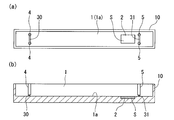
- FIG. 17A is a plan view of the electrophoresis instrument 10
- FIG. 17B is a cross-sectional view of the electrophoresis instrument 10.
- the electrophoresis instrument 11 has a rectangular parallelepiped shape, and an elongated rectangular electrophoresis chamber 1 is formed at the center of the electrophoresis instrument 11.
- a first electrode 30 that is in contact with the acidic side end of the sample separation medium 42 is installed on one end side in the longitudinal direction of the electrophoresis chamber 1, and on the other end side in the longitudinal direction of the electrophoresis chamber 1,
- a second electrode 31 is provided in contact with the basic side end of the sample separation medium 42.
- a first electrode holding part 4 and a second electrode holding part 5 for holding the first electrode 30 and the second electrode 31 are respectively provided on one end side in the longitudinal direction and the other end side in the longitudinal direction of the electrophoresis chamber 1. ing.
- the first electrode holding unit 4 and the second electrode holding unit 5 are provided so as to protrude from the installation surface 1a so as to sandwich the acidic-side end portion and the basic-side end portion of the sample separation medium 42, respectively.
- a sample holder 7 for holding the sample solution is formed on the bottom surface of the electrophoresis chamber 1 (installation surface 1a on which the IEF chip is installed).
- the sample holding unit 7 holds the sample solution in a specific region of the installation surface 1a while suppressing the wetting and spreading of the sample solution.
- the sample holding part 7 is configured as a hydrophilic part having higher hydrophilicity than the installation surface 1a around the sample holding part 7, for example. When the sample holding part 7 is a hydrophilic part, the sample solution supplied to the sample holding part 7 does not spread outside the sample holding part 7. Therefore, the sample solution is stably held in the sample holding unit 7.
- the hydrophilic portion for example, performs a hydrophilic treatment such as UV treatment on a part of the installation surface 1a, and forms a hydrophilic film having high wettability with respect to the sample solution on a part of the installation surface 1a.
- a hydrophilic treatment such as UV treatment
- a water-repellent portion is formed on a part of the installation surface 1a by a method such as forming a water-repellent film on a part of the installation surface 1a, or forming a part of the installation surface 1a with a highly water-repellent material
- the sample solution can be held in a region sandwiched between the water repellent portions.
- the sample holding unit 7 is formed to be elongated from the side close to the first electrode 30 to the side close to the second electrode 31 with the central portion of the electrophoresis chamber 1 interposed therebetween.
- the length of the sample holder 7 is slightly shorter than the distance between the first electrode 30 and the second electrode 31.
- the width of the sample holding part 7 is substantially the same as the width of the sample separation medium 42, and the upper part of the sample holding part 7 is completely covered by the sample separation medium 42.
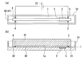
- 18 and 19 are explanatory diagrams of a sample introduction method for introducing a biological sample into a sample separation medium.
- 18 (a) is a plan view of the electrophoresis instrument
- FIGS. 18 (b), 19 (a), 19 (b) and 19 (c) are cross-sectional views of the electrophoresis instrument. is there.
- the sample introduction method of this embodiment is applied to a sample separation method for separating a biological sample by two-dimensional electrophoresis.
- a voltage is applied between the sample introduction step of introducing a biological sample into the sample separation medium 42 using the sample introduction method of this embodiment and the first electrode 30 and the second electrode 32.
- the first electrophoresis step for separating the biological sample by isoelectric focusing, and the sample separation medium 42 from which the biological sample has been separated by the first electrophoresis step is transferred to the second electrophoresis chamber 80.
- a second electrophoresis step in which a voltage is applied to the sample separation medium 42 transported to the second electrophoresis chamber 80 to separate the biological sample by SDS-polyacrylamide gel electrophoresis (SDS-PAGE). And including.
- the first step of supplying the sample solution S containing the biological sample to the installation surface 1a on which the sample separation medium 42 is installed, and the sample separation medium to the sample solution S supplied to the installation surface 1a A second step of bringing the biological sample into contact with the sample separation medium 42.
- a sample solution S containing a biological sample such as protein or nucleic acid is supplied to a sample holding unit 7 provided on the installation surface 1a of the electrophoresis chamber 1. Since the sample holder 7 has a higher affinity for the sample solution S than its peripheral part, the sample solution S does not spread out on the outside of the sample holder 7 and is reliably held by the sample holder 7. Since the sample solution S rises from the installation surface 1a due to the surface tension, the sample solution S reliably contacts the sample separation medium.
- the IEF chip 40 in which the sample separation medium 42 is swollen with a buffer solution is placed in the electrophoresis chamber 1 using the transport arm 45, and is held by the sample holder 7.
- the sample separation medium 42 is brought into contact with the sample solution S.
- As the sample separation medium 42 it is preferable to use an unsaturated swelling sample separation medium in which room for swelling remains. Since the sample solution S rises from the installation surface 1a due to the surface tension, the sample solution S reliably contacts the sample separation medium 42.
- a voltage of about 200 V is applied between the first electrode 30 and the second electrode 31 to introduce a biological sample having a charge into the sample separation medium 42.
- FIG. 19C the sample separation medium 42 is pushed toward the sample holding unit 3 (installation surface 1a) by the transfer arm 45, and the sample separation medium 42 is in close contact with the sample holding unit 7. The voltage is increased to 6000 V and isoelectric focusing is performed.
- the IEF chip 40 is taken out from the electrophoresis chamber 1 using the transfer arm 45. Then, the sample separation medium 42 is immersed in a solution containing SDS for SDS equilibration, and is connected to a sample separation medium (polyacrylamide gel) for SDS-PAGE. Then, the IEF chip 40 is transferred to the second electrophoresis chamber 80 (see FIG. 2) by the transfer arm 45, and second-dimensional electrophoresis (SDS-PAGE) is performed.
- SDS-PAGE second-dimensional electrophoresis
- the sample solution S is supplied to the electrophoresis chamber 1, the sample separation medium 42 is brought into contact with the sample solution S, and the biological sample is introduced into the sample separation medium 42. . Then, a voltage is applied to the sample separation medium 42 in the electrophoresis chamber 1 as it is to perform isoelectric focusing. Therefore, it is not necessary to use dry-preventing oil or filter paper for removing impurities when the biological sample is introduced into the sample separation medium 42. Therefore, there is no complicated operation and data with high reproducibility can be obtained.
- the electrophoresis apparatus 14 of the present embodiment after a biological sample is introduced into the sample separation medium 42, a voltage is applied to the sample separation medium 42 with the sample separation medium 42 being in close contact with the sample holding unit 7. Therefore, the voltage is uniformly applied to the sample separation medium 42, the sample introduction efficiency is high, and uniform focusing and high-resolution separation are performed. Therefore, it is possible to easily separate a biological sample by isoelectric focusing with good reproducibility.
- FIG. 20 is a diagram for explaining how the uniformity of the voltage applied to the sample separation medium 42 changes depending on whether or not the sample separation medium 42 is brought into close contact with the sample holder.
- the sample separation medium 42 is not brought into close contact with the sample holding unit, and a voltage is applied to the sample separation medium 42 with the sample solution S remaining between the sample holding unit and the sample separation medium 42.
- FIG. 20B shows a state in which the sample separation medium 42 is brought into close contact with the sample holding unit, and a voltage is applied to the sample separation medium 42 without the sample solution S interposed between the sample holding unit and the sample separation medium 42.
- the dielectric constants of the sample separation medium 42 and the sample solution S were set to the same dielectric constant as that of water.
- the structure of an electrophoresis apparatus and the chamber for electrophoresis is not limited to this.
- the sample holder 7 is elongated from the vicinity of the first electrode 30 to the vicinity of the second electrode 31, but the position where the sample holder 7 is formed is not particularly limited.
- the sample holding part 3 may be formed at the center of the electrophoresis chamber 1, and the sample holding part 7 is formed at a position deviated from the center of the electrophoresis chamber 1 toward the acidic side or the basic side. May be.
- the sample holding unit 7 is formed to be elongated in the longitudinal direction of the sample separation medium 42, the biological sample is easily introduced uniformly into the entire sample separation medium 42.
- the biological sample is moved when the biological sample is separated by isoelectric focusing. The distance becomes longer and the resolution is improved.
- the width of the sample holder 7 is substantially the same as the width of the sample separation medium 42, but the width of the sample holder 7 is not limited to this.
- the width of the sample holding unit 7 may be larger than the width of the sample separation medium 42 or smaller than the width of the sample separation medium 42.
- the width of a part or the whole of the sample holder 7 is wider than the width of the sample separation medium 42, it is preferable to cover the upper part of the electrophoresis chamber 1 with a cover 50 in order to prevent the sample solution from drying.
- the entire width of the sample holding unit 7 is equal to or smaller than the width of the sample separation medium 42, it is not necessary to cover the upper part of the electrophoresis chamber 1 with the cover 50.
- the sample separation medium 42 is brought into close contact with the sample holder 7 by the transport arm 45, but the method of bringing the sample separation medium 42 into close contact with the sample holder 7 is not limited thereto.
- the sample separation medium 42 may be brought into close contact with the sample holder 7 by swelling of the sample separation medium 42 when the sample separation medium 42 has absorbed the sample solution S.
- FIG. 21 is a diagram showing a schematic configuration of the electrophoresis apparatus 23 of the seventh embodiment.
- This embodiment is different from the sixth embodiment in that the sample holding unit 2 is configured as a depression for injecting a sample solution.
- the sample holding unit 2 is formed to be elongated from the side close to the first electrode 30 to the side close to the second electrode 31 with the central portion of the electrophoresis chamber 1 interposed therebetween.
- the length of the sample holder 3 is slightly shorter than the distance between the first electrode 30 and the second electrode 31.
- the width of the sample holder 3 is substantially the same as the width of the sample separation medium 42, and the upper part of the sample holder 3 is completely covered by the sample separation medium 42.
- the volume of the sample holder 3 is slightly smaller than the volume of the sample solution injected into the sample holder 3.
- the depth of the sample holder 3 is shallower than the thickness of the sample separation medium, and the sample separation medium 42 is in close contact with the bottom surface and the inner wall surface of the sample holder 3 when the sample separation medium is pushed toward the sample holder 3. It is supposed to be.
- 22 and 23 are explanatory diagrams of a sample introduction method for introducing a biological sample into a sample separation medium.
- 22A is a plan view of the electrophoresis instrument 15
- FIGS. 22B, 23A, 23B, and 23C are cross-sectional views of the electrophoresis instrument 15.
- a sample solution S containing a biological sample such as protein or nucleic acid is provided on the installation surface 1a of the electrophoresis chamber 1 with a depth of about 0.5 mm to 1 mm. Injection into the holding unit 3. Optimal experimental results can be obtained if the depth of the sample holder 3 is in a range that is deeper than 0 mm and shallower than 15 mm, and more preferable experimental results are obtained if it is in the range of 0.5 mm to 1 mm. .
- the sample solution S is slightly raised from the installation surface 1a to ensure that the sample solution S comes into contact with the sample separation medium. When the amount of the sample solution S is insufficient, the buffer solution is added to adjust the amount of the sample solution S so that the sample holding unit 3 is filled with the sample solution S.
- the IEF chip 40 in which the sample separation medium 42 is saturated and swelled with a buffer solution is placed in the electrophoresis chamber 1 using the transfer arm 45, and the sample solution S is placed therein.
- the sample holder 2 is covered with the sample separation medium 42, and the sample separation medium 42 is brought into close contact with the sample holder 3.
- a voltage of about 200 V is applied between the first electrode 30 and the second electrode 31 to introduce a biological sample having a charge into the sample separation medium 42.
- the voltage is uniformly applied to the sample separation medium 42, and the biological sample is efficiently introduced into the sample separation medium 42. It becomes like this.
- the sample separation medium 42 is pushed into the sample holder 3 by the transfer arm 45 to increase the voltage to 6000 V, and isoelectric focusing is performed.
- the IEF chip 40 is taken out from the electrophoresis chamber 1 using the transfer arm 45. Then, the sample separation medium 42 is immersed in a solution containing SDS for SDS equilibration, and is connected to a sample separation medium (polyacrylamide gel) for SDS-PAGE. Then, the IEF chip 40 is transferred to the second electrophoresis chamber 80 (see FIG. 2) by the transfer arm 45, and second-dimensional electrophoresis (SDS-PAGE) is performed.
- SDS-PAGE second-dimensional electrophoresis
- the sample solution S is supplied to the electrophoresis chamber 1 and the sample separation medium 42 is placed on the sample solution S to introduce a biological sample. Then, a voltage is applied to the sample separation medium 42 in the electrophoresis chamber 1 as it is to perform isoelectric focusing. Since no anti-drying oil or filter paper for removing impurities is used when the biological sample is introduced into the sample separation medium 42, there is no complicated operation, and highly reproducible data can be obtained.
- the electrophoresis apparatus 23 of the present embodiment after a biological sample is introduced into the sample separation medium 42, a voltage is applied to the sample separation medium 42 with the sample separation medium 42 being in close contact with the sample holder 3. Therefore, the voltage is uniformly applied to the sample separation medium 42, the sample introduction efficiency is high, and uniform focusing and high-resolution separation are performed. Therefore, it is possible to easily separate a biological sample by isoelectric focusing with good reproducibility.
- FIG. 24 is a diagram for explaining how the uniformity of the voltage applied to the sample separation medium 42 varies depending on whether or not the sample separation medium 42 is brought into close contact with the sample holder.
- FIG. 24A shows a state in which the sample separation medium 42 is not brought into close contact with the bottom surface and the inner wall surface of the sample holding unit, and the sample solution S remains between the bottom surface and the inner wall surface of the sample holding unit and the sample separation medium 42.
- 24B shows that the sample separation medium 42 is brought into close contact with the bottom surface and the inner wall surface of the sample holding unit, and the sample solution S is not interposed between the bottom surface and the inner wall surface of the sample holding unit and the sample separation medium 42. It is a figure which shows the mode of the electric force line
- the dielectric constants of the sample separation medium 42 and the sample solution S were set to the same dielectric constant as that of water.
- the electric lines of force inside the sample separation medium 42 are as follows. It becomes uniform, and a uniform voltage is applied to the entire sample separation medium 42. Therefore, uniform focusing and high resolution separation are possible.
- the structure of an electrophoresis apparatus and the chamber for electrophoresis is not limited to this.
- the sample holder 3 is elongated from the vicinity of the first electrode 30 to the vicinity of the second electrode 31, but the position where the sample holder 3 is formed is not particularly limited.
- the sample holder 3 may be formed at the center of the electrophoresis chamber 1, and the sample holder 3 may be formed at a position that is biased toward the acidic side or the basic side from the center of the electrophoresis chamber 1. May be.
- the sample holding unit 3 When the sample holding unit 3 is arranged so as to be biased toward the acidic side or the basic side with respect to the central part of the electrophoresis chamber 1, the biological sample is moved when the biological sample is separated by isoelectric focusing. The distance becomes longer and the resolution is improved.
- the width of the sample holder 3 is substantially the same as the width of the sample separation medium 42, but the width of the sample holder 3 is not limited to this.
- the width of the sample holding unit 3 may be larger than the width of the sample separation medium 42 or smaller than the width of the sample separation medium 42.
- the width of a part or all of the sample holder 3 is wider than the width of the sample separation medium 42, it is preferable to cover the upper part of the electrophoresis chamber 1 with a cover 50 in order to prevent the sample solution from drying.
- the entire width of the sample holder 3 is the same as or narrower than the width of the sample separation medium 42, it is not necessary to cover the upper part of the electrophoresis chamber 1 with the cover 50.
- the sample separation medium 42 is brought into close contact with the bottom surface and the inner wall surface of the sample holding unit 3 by the transfer arm 45.
- the method for bringing the sample separation medium 42 into contact with the bottom surface and the inner wall surface of the sample holding unit 3 is as follows. It is not limited to this.
- the sample separation medium 42 may be brought into close contact with the bottom surface and the inner wall surface of the sample holder 3 by swelling of the sample separation medium 42 when the sample separation medium 42 absorbs the sample solution S.
- both the introduction of the biological sample and the isoelectric focusing are performed in the electrophoresis chamber 1.
- the biological sample is introduced in the electrophoresis chamber 1 and the isoelectric focusing is performed. May be performed in another electrophoresis chamber (third electrophoresis chamber 81).
- the third electrophoresis chamber 81 is an electrophoresis chamber having a flat installation surface on which the sample separation medium 42 is installed.
- the third electrophoresis chamber 81 is different from the electrophoresis chamber 1 in that no depression is formed on the installation surface, but the other configuration is the same as the electrophoresis chamber 1. Therefore, the detailed configuration of the third electrophoresis chamber 81 is not shown.
- the sample separation medium 42 into which the biological sample has been introduced in the electrophoresis chamber 1 is installed in the third electrophoresis chamber 81 (see FIG. 16) using the transfer arm 45 (see FIG. 16). Then, a voltage of 6000 V is applied to the sample separation medium 42 using the first electrode and the second electrode provided in the third electrophoresis chamber 81, and the biological sample is separated by isoelectric focusing. In this case, since the isoelectric focusing is performed using the third electrophoresis chamber 81 having a flat installation surface, a uniform voltage is applied to the entire sample separation medium 42, and uniform focusing and high-resolution separation are achieved. It becomes possible.
- FIG. 25A is a plan view of the electrophoresis instrument 16 of the third embodiment
- FIG. 25B is a cross-sectional view of the electrophoresis instrument 16.
- This embodiment is different from the seventh embodiment in that the sample holding unit 17 is arranged to be biased toward the acidic side or the basic side with respect to the central part of the electrophoresis chamber 1.
- the sample holder 17 is provided on the side closer to the second electrode 31 than the first electrode 30, but the sample holder 17 is closer to the first electrode 30 than the second electrode 31. It may be provided.
- the volume of the sample holding unit 17 is preferably slightly smaller than the volume of the sample solution injected into the sample holding unit 17. According to this configuration, when the sample solution is injected into the sample holding unit 17, the sample solution rises from the installation surface 1 a and the sample solution reliably contacts the sample separation medium 42.
- the area of the sample holding unit 17 is not particularly limited as long as it can ensure a sufficient contact area between the sample solution and the sample separation medium 42.
- the width of the sample holding unit 17 is larger than the width of the sample separation medium 42, but the width of the sample holding unit 17 may be smaller than the width of the sample separation medium 42.
- the width of the sample holder 17 is wider than the width of the sample separation medium 42, the upper part of the sample holder 17 is not completely covered by the sample separation medium 42. It becomes easy to discharge bubbles generated when contacting the sample solution to the outside of the sample solution.
- the upper part of the electrophoresis chamber 1 is covered with a cover 50 (see FIG. 15) in order to prevent the sample solution from drying. Is preferred.
- the entire width of the sample holder 17 is the same as or narrower than the width of the sample separation medium 42, it is not necessary to cover the upper part of the electrophoresis chamber 1 with the cover 50 (see FIG. 15).
- 26 and 27 are explanatory diagrams of a sample introduction method for introducing a biological sample into a sample separation medium.
- 26A is a plan view of the electrophoresis instrument 16
- FIGS. 26B, 27A, 27B, and 27C are cross sections of the electrophoresis instrument 16.
- a sample solution S containing a biological sample such as protein or nucleic acid is provided on the installation surface 1a of the electrophoresis chamber 1 with a depth of about 0.5 mm to 1 mm. Inject into the holding part 17. Optimum experimental results can be obtained if the depth of the sample holding part 17 is in a range deeper than 0 mm and shallower than 15 mm, and more preferable experimental results are obtained in a range of 0.5 mm to 1 mm. .
- the sample solution S is slightly raised from the installation surface 1a to ensure that the sample solution S comes into contact with the sample separation medium. When the amount of the sample solution S is insufficient, the amount of the sample solution S is adjusted by adding a buffer solution so that the sample holding unit 17 is filled with the sample solution S.
- the IEF chip 40 in which the sample separation medium 42 is saturated and swelled with a buffer solution is placed in the electrophoresis chamber 1 using the transfer arm 45, and the sample solution S is placed therein.
- the sample holder 17 is covered with the sample separation medium 42, and the sample separation medium 42 is brought into close contact with the sample holder 17.
- a voltage of about 200 V is applied between the first electrode 30 and the second electrode 31 to introduce a biological sample having a charge into the sample separation medium 42.
- the sample separation medium 42 is pushed into the sample holder 17 by the transfer arm 45 to increase the voltage to 6000 V, and isoelectric focusing is performed.
- the IEF chip 40 is taken out from the electrophoresis chamber 1 using the transfer arm 45. Then, the sample separation medium 42 is immersed in a solution containing SDS for SDS equilibration, and is connected to a sample separation medium (polyacrylamide gel) for SDS-PAGE. Then, the IEF chip 40 is transferred to the second electrophoresis chamber 80 (see FIG. 2) by the transfer arm 45, and second-dimensional electrophoresis (SDS-PAGE) is performed.
- SDS-PAGE second-dimensional electrophoresis
- the sample holding unit 17 is arranged so as to be biased toward the acidic side or the basic side with respect to the central part of the electrophoresis chamber 1. Therefore, when the biological sample is separated by isoelectric focusing, the moving distance of the biological sample becomes long and the resolution is improved.
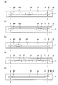
- FIG. 28A to FIG. 28E are plan views showing other variations of the sample holder 19 provided in the electrophoresis instrument 18.
- FIG. 28A shows an example in which an elliptical sample holding part 19 is provided in the central part of the electrophoresis chamber 1.
- FIG. 28B is an example in which the elliptical sample holding unit 19 is provided to be biased toward the second electrode 31 with respect to the center of the electrophoresis chamber 1.
- FIG. 28C is an example in which the elliptical sample holding part 19 is provided in the first electrode 30 side with respect to the central part of the electrophoresis chamber 1.
- FIG. 28D shows an example in which three elliptical sample holders 19 are spaced apart from each other along the longitudinal direction of the electrophoresis chamber 1.
- the substantially rectangular sample holding part 19 in which the sides on the first electrode 30 side and the second electrode 31 side are curved in an arc shape is attached to the first electrode 30 across the central part of the electrophoresis chamber 1.
- the strip is formed from the near side to the side near the second electrode 31.
- sample holding part 19 may be comprised as a hydrophilic part which has affinity with a sample solution, and may be comprised as a hollow for inject
- the sample holders 3, 7, 17, and 19 that hold the sample solution S are provided on the installation surface 1a of the electrophoresis chamber 1.
- the sample holders 3, 7, 17, and 19 suppress the wetting and spreading of the sample solution S.
- the sample holders 3, 7, 17, and 19 may not be provided on the installation surface 1a of the electrophoresis chamber 1.
- the width of the electrophoresis chamber 1 is substantially the same as the width of the sample separation medium 42, wetting and spreading of the sample solution S is not a problem. Therefore, it is possible to introduce a biological sample into the sample separation medium 42 by simply supplying the sample solution S to the installation surface 1a and covering the sample separation medium 42 thereon without providing the sample holding portion. . After the biological sample is introduced into the sample separation medium 42, the sample separation medium 42 is brought into close contact with the installation surface 1 a of the electrophoresis chamber 1 and a voltage is applied between the first electrode 30 and the second electrode 31. Uniform focusing and high resolution separation are performed.
- a sample introduction method is a sample introduction method for introducing the biological sample into a sample separation medium for separating a biological sample by electrophoresis, the installation surface on which the sample separation medium is installed, and the sample
- a sample holding unit that has a first electrode and a second electrode connected to both ends of the separation medium, and holds the sample solution while suppressing wetting and spreading of the sample solution containing the biological sample on the installation surface
- the sample solution in the second step, is brought into contact with the sample separation medium while a voltage is applied between the first electrode and the second electrode. May be.
- the sample holding portion may be a hydrophilic portion having a higher hydrophilicity than the installation surface around the sample holding portion.
- the sample holding portion may be a depression provided on the installation surface.
- the depth of the recess may be smaller than the thickness of the sample separation medium.
- the sample holding portion is provided on a side closer to the first electrode than the second electrode or a side closer to the second electrode than the first electrode. It may be.
- the sample separation medium may be a swollen gel.
- a gel that is not completely swollen is preferable because it can absorb the sample solution.
- a sample separation method includes a sample introduction step of introducing the biological sample into the sample separation medium using the sample introduction method of the present invention, and between the first electrode and the second electrode. Applying a voltage and separating the biological sample by isoelectric focusing.
- a voltage is applied between the first electrode and the second electrode in a state where the sample separation medium is in close contact with the installation surface. May be applied.
- the first method is a method in which the unsaturated swelling gel as the sample separation medium absorbs the sample solution and swells, so that the sample separation medium adheres to the installation surface of the electrophoresis chamber.
- the second method is a method in which the sample separation medium is pressed against the installation surface of the electrophoresis chamber by the transfer arm. That is, in the sample introduction step, the sample separation medium may adhere to the installation surface by the sample separation medium absorbing and swelling the sample solution.
- the sample separation medium may be brought into close contact with the installation surface by pressing the sample separation medium against the installation surface by a transfer arm.
- the sample separation method includes a transporting step of transporting the sample separation medium from which the biological sample has been separated by the first electrophoresis step to a second electrophoresis chamber; A second electrophoresis step of applying a voltage to the sample separation medium transported to the second electrophoresis chamber and separating the biological sample by SDS-polyacrylamide gel electrophoresis.
- a sample separation method includes a sample introduction step of introducing the biological sample into the sample separation medium using the sample introduction method of the present invention, a flat installation surface on which the sample separation medium is installed, The sample separation medium is placed in a third electrophoresis chamber having a first electrode and a second electrode connected to both ends of the sample separation medium, and the sample separation medium is used for the third electrophoresis A voltage is applied between the first electrode and the second electrode of the third electrophoresis chamber in a state of being in close contact with the installation surface of the chamber, and the biological sample is subjected to isoelectric focusing. Separating the first electrophoresis step.
- the sample separation method includes a transporting step of transporting the sample separation medium from which the biological sample has been separated by the first electrophoresis step to a second electrophoresis chamber; A second electrophoresis step of applying a voltage to the sample separation medium transported to the second electrophoresis chamber and separating the biological sample by SDS-polyacrylamide gel electrophoresis.
- An electrophoresis instrument includes an installation surface on which a sample separation medium that separates a biological sample by electrophoresis, a first electrode and a second electrode connected to both ends of the sample separation medium, , And a sample holder for holding the sample solution while suppressing the wetting and spreading of the sample solution containing the biological sample is provided on the installation surface of the electrophoresis chamber.
- biological samples such as proteins and nucleic acids are separated by electrophoresis, a sample separation medium containing the separated biological samples is cut out and identified by a mass spectrometer, or the separated biological samples are separated from the sample separation medium.
- a sample separation medium containing the separated biological samples is cut out and identified by a mass spectrometer, or the separated biological samples are separated from the sample separation medium.
- Electrophoresis chamber 1a, 71a ... Installation surface, 2, 61, 63, 65, 69 ... Depression, 3, 7, 17, 19 ... Sample holding part 10, 11, 15, 16, 18, 60, 62, 64, 66 ... Electrophoresis device, 12, 14, 23 ... Electrophoresis device, 30 ... First electrode, 31 ... Second electrode, 42 ... Sample separation medium, 45 ... Transfer arm, 80 ... Second Electrophoresis chamber, 81 ... Third electrophoresis chamber, S ... Sample solution
Landscapes
- Health & Medical Sciences (AREA)
- Life Sciences & Earth Sciences (AREA)
- Molecular Biology (AREA)
- Chemical & Material Sciences (AREA)
- Biochemistry (AREA)
- Electrochemistry (AREA)
- Physics & Mathematics (AREA)
- Analytical Chemistry (AREA)
- Chemical Kinetics & Catalysis (AREA)
- General Health & Medical Sciences (AREA)
- General Physics & Mathematics (AREA)
- Immunology (AREA)
- Pathology (AREA)
- Electrostatic Separation (AREA)
- Sampling And Sample Adjustment (AREA)
- Peptides Or Proteins (AREA)
Abstract
La présente invention porte sur un instrument d'électrophorèse avec lequel il est possible de réaliser facilement une séparation d'un échantillon biologique avec une bonne reproductibilité par focalisation isoélectrique. L'instrument d'électrophorèse (10) comprend une chambre d'électrophorèse (1) dans laquelle est installé un milieu de séparation d'échantillon (42) qui sépare un échantillon biologique par électrophorèse. Une dépression (2) pour infusion d'une solution d'échantillon comprenant l'échantillon biologique est disposée sur une surface d'installation (1a) sur la chambre d'électrophorèse (1), ladite surface d'installation (1) étant où le milieu de séparation d'échantillon (42) est installé.
Priority Applications (2)
| Application Number | Priority Date | Filing Date | Title |
|---|---|---|---|
| CN201380034370.0A CN104412103A (zh) | 2012-06-29 | 2013-06-27 | 电泳用器具、电泳装置、样本导入方法以及样本分离方法 |
| US14/410,688 US20150160158A1 (en) | 2012-06-29 | 2013-06-27 | Electrophoresis instrument, electrophoresis device, sample introduction method, and sample separation method |
Applications Claiming Priority (4)
| Application Number | Priority Date | Filing Date | Title |
|---|---|---|---|
| JP2012147315A JP5502150B2 (ja) | 2012-06-29 | 2012-06-29 | サンプル導入方法、サンプル分離方法および電気泳動用器具 |
| JP2012147689A JP5502151B2 (ja) | 2012-06-29 | 2012-06-29 | 電気泳動用器具、電気泳動装置、サンプル導入方法およびサンプル分離方法 |
| JP2012-147315 | 2012-06-29 | ||
| JP2012-147689 | 2012-06-29 |
Publications (1)
| Publication Number | Publication Date |
|---|---|
| WO2014003103A1 true WO2014003103A1 (fr) | 2014-01-03 |
Family
ID=49783240
Family Applications (1)
| Application Number | Title | Priority Date | Filing Date |
|---|---|---|---|
| PCT/JP2013/067617 Ceased WO2014003103A1 (fr) | 2012-06-29 | 2013-06-27 | Instrument d'électrophorèse, dispositif d'électrophorèse, procédé d'introduction d'échantillon et procédé de séparation d'échantillon |
Country Status (3)
| Country | Link |
|---|---|
| US (1) | US20150160158A1 (fr) |
| CN (1) | CN104412103A (fr) |
| WO (1) | WO2014003103A1 (fr) |
Families Citing this family (2)
| Publication number | Priority date | Publication date | Assignee | Title |
|---|---|---|---|---|
| US10533967B2 (en) * | 2015-04-10 | 2020-01-14 | Panasonic Intellectual Property Management Co., Ltd. | Electrophoretic support body and electrophoretic device |
| WO2018030052A1 (fr) * | 2016-08-10 | 2018-02-15 | パナソニックIpマネジメント株式会社 | Support d'électrophorèse, dispositif d'électrophorèse et procédé de fabrication de support d'électrophorèse |
Citations (6)
| Publication number | Priority date | Publication date | Assignee | Title |
|---|---|---|---|---|
| JPS61104248A (ja) * | 1984-10-29 | 1986-05-22 | Hitachi Ltd | 電気泳動装置 |
| JP2004069387A (ja) * | 2002-08-02 | 2004-03-04 | Moritex Corp | 二次元電気泳動方法、装置及びそのゲル保持器具 |
| JP2005345334A (ja) * | 2004-06-04 | 2005-12-15 | Shimadzu Corp | 電気泳動方法 |
| JP2006258685A (ja) * | 2005-03-18 | 2006-09-28 | National Institute Of Advanced Industrial & Technology | 二次元電気泳動法用試料注入器具及びそれを含む二次元電気泳動用装置並びに該装置を用いた二次元電気泳動法 |
| JP2007064848A (ja) * | 2005-08-31 | 2007-03-15 | Sharp Corp | 自動化2次元電気泳動装置および装置構成器具 |
| JP2008164319A (ja) * | 2006-12-27 | 2008-07-17 | National Institute Of Advanced Industrial & Technology | 電気泳動用乾燥媒体への試料の導入方法及びそのための器具 |
-
2013
- 2013-06-27 US US14/410,688 patent/US20150160158A1/en not_active Abandoned
- 2013-06-27 CN CN201380034370.0A patent/CN104412103A/zh active Pending
- 2013-06-27 WO PCT/JP2013/067617 patent/WO2014003103A1/fr not_active Ceased
Patent Citations (6)
| Publication number | Priority date | Publication date | Assignee | Title |
|---|---|---|---|---|
| JPS61104248A (ja) * | 1984-10-29 | 1986-05-22 | Hitachi Ltd | 電気泳動装置 |
| JP2004069387A (ja) * | 2002-08-02 | 2004-03-04 | Moritex Corp | 二次元電気泳動方法、装置及びそのゲル保持器具 |
| JP2005345334A (ja) * | 2004-06-04 | 2005-12-15 | Shimadzu Corp | 電気泳動方法 |
| JP2006258685A (ja) * | 2005-03-18 | 2006-09-28 | National Institute Of Advanced Industrial & Technology | 二次元電気泳動法用試料注入器具及びそれを含む二次元電気泳動用装置並びに該装置を用いた二次元電気泳動法 |
| JP2007064848A (ja) * | 2005-08-31 | 2007-03-15 | Sharp Corp | 自動化2次元電気泳動装置および装置構成器具 |
| JP2008164319A (ja) * | 2006-12-27 | 2008-07-17 | National Institute Of Advanced Industrial & Technology | 電気泳動用乾燥媒体への試料の導入方法及びそのための器具 |
Also Published As
| Publication number | Publication date |
|---|---|
| CN104412103A (zh) | 2015-03-11 |
| US20150160158A1 (en) | 2015-06-11 |
Similar Documents
| Publication | Publication Date | Title |
|---|---|---|
| CN102077084B (zh) | 样品分离吸附器具 | |
| CN101111762B (zh) | 通过双向电泳同时分离生物分子的方法和仪器 | |
| Gao et al. | Cross-linked polyacrylamide coating for capillary isoelectric focusing | |
| JP5214979B2 (ja) | エレクトロブロッティング装置、システム及びキット、並びにそれらの使用方法 | |
| JP4586179B2 (ja) | 二次元電気泳動法用試料注入器具及びそれを含む二次元電気泳動用装置並びに該装置を用いた二次元電気泳動法 | |
| JP2008522144A5 (fr) | ||
| Yang et al. | Microfluidic 2-D PAGE using multifunctional in situ polyacrylamide gels and discontinuous buffers | |
| WO2014003103A1 (fr) | Instrument d'électrophorèse, dispositif d'électrophorèse, procédé d'introduction d'échantillon et procédé de séparation d'échantillon | |
| KR102064388B1 (ko) | 단일 지점 검출 방식 미소유체 등전점 전기영동 및 미소유체 칩 | |
| US20080272002A1 (en) | System and Method for Proteomics | |
| JP4822350B2 (ja) | 電気泳動用乾燥媒体への試料の導入方法及びそのための器具 | |
| Guttman et al. | Ultrathin‐layer gel electrophoresis of biopolymers | |
| US6057106A (en) | Sample buffer and methods for high resolution gel electrophoresis of denatured nucleic acids | |
| JP5502151B2 (ja) | 電気泳動用器具、電気泳動装置、サンプル導入方法およびサンプル分離方法 | |
| JP5502150B2 (ja) | サンプル導入方法、サンプル分離方法および電気泳動用器具 | |
| JP6635385B2 (ja) | 電気泳動支持体及び電気泳動装置 | |
| WO2016098648A1 (fr) | Appareil d'analyse biomoléculaire | |
| CN106248763A (zh) | 一种在纸基分析装置上等电聚焦和分离两性物质的方法 | |
| JP2016109511A (ja) | サンプル分離器具およびサンプル分離吸着装置 | |
| Chiu et al. | A simple, rapid, and sensitive method for analysis of SYPRO Red labeled sodium dodecyl sulfate‐protein complexes by capillary electrophoresis with laser‐induced fluorescence | |
| JP4590615B2 (ja) | 二次元電気泳動方法 | |
| Mikšík | Capillary gel and sieving electrophoresis | |
| Rabilloud et al. | Two-dimensional SDS-PAGE fractionation of biological samples for biomarker discovery | |
| WO2015064736A1 (fr) | Milieu d'électrophorèse unidimensionnelle pour électrophorèse bidimensionnelle, support sur lequel est maintenu le milieu, dispositif d'électrophorèse bidimensionnelle utilisant le milieu, procédé d'électrophorèse bidimensionnelle utilisant le milieu et gabarit | |
| Jabasini et al. | Low viscous separation media for genomics and proteomics analysis on microchip electrophoresis system |
Legal Events
| Date | Code | Title | Description |
|---|---|---|---|
| 121 | Ep: the epo has been informed by wipo that ep was designated in this application |
Ref document number: 13808662 Country of ref document: EP Kind code of ref document: A1 |
|
| WWE | Wipo information: entry into national phase |
Ref document number: 14410688 Country of ref document: US |
|
| NENP | Non-entry into the national phase |
Ref country code: DE |
|
| 122 | Ep: pct application non-entry in european phase |
Ref document number: 13808662 Country of ref document: EP Kind code of ref document: A1 |