WO2014003104A1 - Dispositif de station de base, dispositif de station mobile, procédé de communication sans fil, circuit intégré et système de communication sans fil - Google Patents
Dispositif de station de base, dispositif de station mobile, procédé de communication sans fil, circuit intégré et système de communication sans fil Download PDFInfo
- Publication number
- WO2014003104A1 WO2014003104A1 PCT/JP2013/067620 JP2013067620W WO2014003104A1 WO 2014003104 A1 WO2014003104 A1 WO 2014003104A1 JP 2013067620 W JP2013067620 W JP 2013067620W WO 2014003104 A1 WO2014003104 A1 WO 2014003104A1
- Authority
- WO
- WIPO (PCT)
- Prior art keywords
- uplink
- flexible subframe
- physical
- subframe
- scheduled
- Prior art date
- Legal status (The legal status is an assumption and is not a legal conclusion. Google has not performed a legal analysis and makes no representation as to the accuracy of the status listed.)
- Ceased
Links
Images





Classifications
-
- H—ELECTRICITY
- H04—ELECTRIC COMMUNICATION TECHNIQUE
- H04L—TRANSMISSION OF DIGITAL INFORMATION, e.g. TELEGRAPHIC COMMUNICATION
- H04L27/00—Modulated-carrier systems
- H04L27/26—Systems using multi-frequency codes
- H04L27/2601—Multicarrier modulation systems
- H04L27/2602—Signal structure
-
- H—ELECTRICITY
- H04—ELECTRIC COMMUNICATION TECHNIQUE
- H04B—TRANSMISSION
- H04B7/00—Radio transmission systems, i.e. using radiation field
- H04B7/24—Radio transmission systems, i.e. using radiation field for communication between two or more posts
- H04B7/26—Radio transmission systems, i.e. using radiation field for communication between two or more posts at least one of which is mobile
- H04B7/2643—Radio transmission systems, i.e. using radiation field for communication between two or more posts at least one of which is mobile using time-division multiple access [TDMA]
- H04B7/2656—Radio transmission systems, i.e. using radiation field for communication between two or more posts at least one of which is mobile using time-division multiple access [TDMA] for structure of frame, burst
-
- H—ELECTRICITY
- H04—ELECTRIC COMMUNICATION TECHNIQUE
- H04L—TRANSMISSION OF DIGITAL INFORMATION, e.g. TELEGRAPHIC COMMUNICATION
- H04L27/00—Modulated-carrier systems
- H04L27/26—Systems using multi-frequency codes
- H04L27/2601—Multicarrier modulation systems
- H04L27/2602—Signal structure
- H04L27/261—Details of reference signals
-
- H—ELECTRICITY
- H04—ELECTRIC COMMUNICATION TECHNIQUE
- H04L—TRANSMISSION OF DIGITAL INFORMATION, e.g. TELEGRAPHIC COMMUNICATION
- H04L5/00—Arrangements affording multiple use of the transmission path
- H04L5/003—Arrangements for allocating sub-channels of the transmission path
- H04L5/0053—Allocation of signalling, i.e. of overhead other than pilot signals
-
- H—ELECTRICITY
- H04—ELECTRIC COMMUNICATION TECHNIQUE
- H04L—TRANSMISSION OF DIGITAL INFORMATION, e.g. TELEGRAPHIC COMMUNICATION
- H04L5/00—Arrangements affording multiple use of the transmission path
- H04L5/14—Two-way operation using the same type of signal, i.e. duplex
-
- H—ELECTRICITY
- H04—ELECTRIC COMMUNICATION TECHNIQUE
- H04L—TRANSMISSION OF DIGITAL INFORMATION, e.g. TELEGRAPHIC COMMUNICATION
- H04L5/00—Arrangements affording multiple use of the transmission path
- H04L5/14—Two-way operation using the same type of signal, i.e. duplex
- H04L5/1469—Two-way operation using the same type of signal, i.e. duplex using time-sharing
-
- H—ELECTRICITY
- H04—ELECTRIC COMMUNICATION TECHNIQUE
- H04W—WIRELESS COMMUNICATION NETWORKS
- H04W28/00—Network traffic management; Network resource management
- H04W28/02—Traffic management, e.g. flow control or congestion control
- H04W28/06—Optimizing the usage of the radio link, e.g. header compression, information sizing, discarding information
-
- H—ELECTRICITY
- H04—ELECTRIC COMMUNICATION TECHNIQUE
- H04W—WIRELESS COMMUNICATION NETWORKS
- H04W72/00—Local resource management
- H04W72/02—Selection of wireless resources by user or terminal
-
- H—ELECTRICITY
- H04—ELECTRIC COMMUNICATION TECHNIQUE
- H04W—WIRELESS COMMUNICATION NETWORKS
- H04W72/00—Local resource management
- H04W72/04—Wireless resource allocation
- H04W72/044—Wireless resource allocation based on the type of the allocated resource
- H04W72/0446—Resources in time domain, e.g. slots or frames
-
- H—ELECTRICITY
- H04—ELECTRIC COMMUNICATION TECHNIQUE
- H04W—WIRELESS COMMUNICATION NETWORKS
- H04W72/00—Local resource management
- H04W72/50—Allocation or scheduling criteria for wireless resources
- H04W72/51—Allocation or scheduling criteria for wireless resources based on terminal or device properties
-
- H—ELECTRICITY
- H04—ELECTRIC COMMUNICATION TECHNIQUE
- H04L—TRANSMISSION OF DIGITAL INFORMATION, e.g. TELEGRAPHIC COMMUNICATION
- H04L5/00—Arrangements affording multiple use of the transmission path
- H04L5/003—Arrangements for allocating sub-channels of the transmission path
- H04L5/0048—Allocation of pilot signals, i.e. of signals known to the receiver
Definitions
- the present invention relates to a base station device, a mobile station device, a wireless communication method, an integrated circuit, and a wireless communication system.
- LTE Long Term Evolution
- EUTRA Evolved Universal Terrestrial Radio Access
- 3GPP Third Generation Partnership Project
- LTE an orthogonal frequency division multiplexing ( ⁇ OFDM) method is used as a downlink communication method.
- SC-FDMA Single-Carrier Frequency Frequency Division Multiple Multiple Access
- UE User Equipment
- LTE is a cellular communication system in which a plurality of areas covered by a base station apparatus are arranged in a cell shape. A single base station apparatus may manage a plurality of cells.
- LTE is compatible with TDD (Time Division Duplex).
- LTE employing the TDD scheme is also referred to as TD-LTE or LTE TDD.
- TDD is a technology that enables full-duplex communication in a single frequency band by time-division multiplexing uplink signals and downlink signals.
- Non-Patent Document 1 a method using a flexible subframe is presented as a method for realizing traffic adaptation.
- the base station apparatus can receive an uplink signal or transmit a downlink signal in a flexible subframe.
- the mobile station apparatus regards the flexible subframe as a downlink subframe unless the base station apparatus is instructed to transmit an uplink signal in the flexible subframe.
- the present invention has been made in view of the above points, and an object of the present invention is to provide a base station apparatus, a mobile station apparatus, a radio communication method, a radio communication system, and an integration that can efficiently communicate using flexible subframes.
- An object is to provide a circuit.
- the mobile station apparatus of the present invention is a mobile station apparatus that communicates with a base station apparatus, and the physical uplink shared channel and the sounding reference signal are not scheduled in the first flexible subframe, and the first flexible subframe is not scheduled.
- the downlink grant used for scheduling of the physical downlink shared channel is monitored in the first flexible subframe.
- the physical downlink shared channel except the last part in the time domain is received based on the detected downlink grant.
- the present invention provides a physical uplink shared channel in the first flexible subframe and the second flexible subframe in a subframe before the first flexible subframe in the mobile station apparatus. And / or monitor the uplink grant used for scheduling the sounding reference signal.
- the radio communication method of the present invention is a radio communication method used for a mobile station apparatus communicating with a base station apparatus, and a physical uplink shared channel and a sounding reference signal are scheduled in a first flexible subframe. If at least the physical uplink shared channel is scheduled in the second flexible subframe immediately after the first flexible subframe, the physical downlink shared channel is scheduled in the first flexible subframe. In the first flexible subframe, the physical downlink shared channel excluding the last part in the time domain is received based on the detected downlink grant in the first flexible subframe.
- the integrated circuit of the present invention is an integrated circuit mounted on a mobile station apparatus that communicates with a base station apparatus, and a physical uplink shared channel and a sounding reference signal are scheduled in a first flexible subframe.
- a physical uplink shared channel and a sounding reference signal are scheduled in a first flexible subframe.
- the physical downlink shared channel is scheduled in the first flexible subframe.
- the mobile station To exhibit to the location.
- the radio communication system of the present invention is a radio communication system in which a mobile station apparatus and a base station apparatus communicate with each other, and the mobile station apparatus uses a physical uplink shared channel and sounding in a first flexible subframe.
- a reference signal is not scheduled and at least the physical uplink shared channel is scheduled in the second flexible subframe immediately after the first flexible subframe, the physical downlink in the first flexible subframe
- the downlink grant used for the scheduling of the shared channel is monitored, and the physical downlink shared channel except the last part in the time domain is received based on the detected downlink grant in the first flexible subframe. To do.
- the mobile station apparatus of the present invention is a mobile station apparatus that communicates with the base station apparatus, and the physical uplink shared channel and the sounding reference signal are not scheduled in the first flexible subframe, and A physical downlink shared channel in the first flexible subframe and the second flexible subframe when at least the physical uplink shared channel is scheduled in the second flexible subframe immediately after the flexible subframe. Do not monitor downlink grants used for scheduling.
- the radio communication method of the present invention is a radio communication method used for a mobile station apparatus that communicates with a base station apparatus, and a physical uplink shared channel and a sounding reference signal are scheduled in a first flexible subframe. If at least the physical uplink shared channel is scheduled in the second flexible subframe immediately after the first flexible subframe, the first flexible subframe and the second flexible subframe Does not monitor the downlink grant used for scheduling the physical downlink shared channel.
- the integrated circuit of the present invention is an integrated circuit mounted on a mobile station apparatus that communicates with a base station apparatus, and a physical uplink shared channel and a sounding reference signal are scheduled in a first flexible subframe.
- a physical uplink shared channel and a sounding reference signal are scheduled in a first flexible subframe.
- the radio communication system of the present invention is a radio communication system in which a mobile station apparatus and a base station apparatus communicate with each other, and the mobile station apparatus includes a physical uplink shared channel and sounding in a first flexible subframe.
- the reference signal is not scheduled and at least the physical uplink shared channel is scheduled in the second flexible subframe immediately after the first flexible subframe, the first flexible subframe and the second flexible subframe In this flexible subframe, the downlink grant used for scheduling of the physical downlink shared channel is not monitored.
- the mobile station apparatus of the present invention is a mobile station apparatus that communicates with a base station apparatus, wherein an uplink physical channel and an uplink physical signal are transmitted in at least one of flexible subframes continuous in a time domain.
- a flexible subframe in which either or both of the uplink physical channel and the uplink physical signal are scheduled is referred to as an uplink subframe.
- the mobile station apparatus does not monitor the downlink grant used in the downlink physical channel schedule in the flexible subframe regarded as the uplink subframe.
- the mobile station apparatus monitors a downlink grant used for a downlink physical channel schedule in a flexible subframe regarded as the downlink subframe.
- the radio communication method of the present invention is a radio communication method used for a mobile station apparatus communicating with a base station apparatus, and an uplink physical channel in at least one of flexible subframes continuous in the time domain. And / or uplink physical signal is scheduled, among the continuous flexible subframes, a flexible subframe in which either or both of the uplink physical channel and the uplink physical signal are scheduled Are considered as uplink subframes, and among the consecutive subframes, uplink the flexible subframes before the flexible subframes scheduled for the uplink physical channel and / or the uplink physical signal.
- sub A flexible subframe after the last flexible subframe in which the uplink physical channel and / or the uplink physical signal are scheduled among the consecutive subframes is regarded as a downlink subframe. It is considered.
- An integrated circuit according to the present invention is an integrated circuit mounted on a mobile station apparatus communicating with a base station apparatus, and an uplink physical channel in at least one of flexible subframes continuous in a time domain.
- a flexible subframe in which either or both of the uplink physical channel and the uplink physical signal are scheduled among the continuous flexible subframes Assuming that the subframe is an uplink subframe, among the consecutive subframes, a flexible subframe before the flexible subframe in which either or both of the uplink physical channel and the uplink physical signal are scheduled is an uplink subframe. flame Assuming that, among the consecutive subframes, a flexible subframe after the last flexible subframe scheduled for the uplink physical channel and / or the uplink physical signal is regarded as a downlink subframe. The function is exhibited by the mobile station device.
- the radio communication system of the present invention is a radio communication system in which a mobile station apparatus and a base station apparatus communicate with each other.
- the uplink physical channel and / or the uplink physical signal are scheduled among the continuous flexible subframes.
- Flexible subframes are regarded as uplink subframes, and among the consecutive subframes, flexible subframes prior to the flexible subframe in which the uplink physical channel and / or the uplink physical signal are scheduled are scheduled. Flame It is considered as an uplink subframe, and among the consecutive subframes, the flexible subframe after the last flexible subframe scheduled for the uplink physical channel and / or the uplink physical signal is downloaded. Considered a link subframe.
- the base station apparatus and the mobile station apparatus can efficiently communicate using the flexible subframe.
- the mobile station device communicates with a single cell.
- the present invention can also be applied when the mobile station apparatus communicates with a plurality of cells.
- a technique in which a mobile station apparatus communicates with a plurality of cells is referred to as cell aggregation or carrier aggregation.
- cell aggregation the present invention may be applied to each of a plurality of cells.
- cell aggregation the present invention may be applied to some of a plurality of cells.
- a TDD (Time Division Division Duplex) scheme is applied.
- FIG. 1 is a conceptual diagram of the wireless communication system of the present embodiment.
- the radio communication system includes mobile station apparatuses 1 A to 1 C and a base station apparatus 3.
- the mobile station apparatuses 1A to 1C are referred to as the mobile station apparatus 1.
- the following uplink physical channels are used in uplink radio communication from the mobile station apparatus 1 to the base station apparatus 3.
- the uplink physical channel is used for transmitting information output from an upper layer.
- -PUCCH Physical Uplink Control Channel
- PUSCH Physical Uplink Shared Channel
- PRACH Physical Random Access Channel
- Uplink Control Information is a physical channel used for transmitting uplink control information (Uplink Control Information: UCI).
- Uplink control information includes downlink channel state information (Channel State Information: CSI), scheduling request indicating a request for PUSCH resources (Scheduling Request: SR), and success / failure of decoding of downlink data received by the mobile station apparatus 1.
- CSI Downlink Channel State Information
- SR scheduling Request indicating a request for PUSCH resources
- SR scheduling Request indicating a request for PUSCH resources
- ACK acknowledgement
- NACK negative-acknowledgement
- the PUSCH is a physical channel used to transmit uplink data (Uplink-Shared Channel: UL-SCH).
- the PUSCH may also be used to transmit ACK / NACK and / or channel state information along with uplink data.
- the PUSCH may also be used to transmit only ACK / NACK and / or channel state information.
- PRACH is a physical channel used to transmit a random access preamble.
- the main purpose of the PRACH is that the mobile station device 1 synchronizes with the base station device 3 in the time domain.
- the PRACH is used to request initial connection establishment (initial connection establishment) procedures, handover procedures, connection re-establishment (connection-re-establishment) procedures, synchronization for uplink transmission (timing adjustment), and uplink radio resource allocation. Used.
- uplink physical signals are used in uplink wireless communication.
- the uplink physical signal is not used for transmitting information output from the upper layer, but is used by the physical layer.
- UL RS Uplink Reference Signal
- DMRS Demodulation Reference Signal
- SRS Sounding Reference Signal
- DMRS is related to transmission of PUSCH or PUCCH.
- DMRS is time-multiplexed with PUSCH or PUCCH.
- the base station apparatus 3 uses DMRS to perform propagation channel correction for PUSCH or PUCCH.
- transmitting both PUSCH and DMRS is simply referred to as transmitting PUSCH.
- transmitting both PUCCH and DMRS is simply referred to as transmitting PUCCH.
- the base station apparatus 3 uses SRS to measure the uplink channel state.
- the mobile station device 1 transmits the first SRS in the first resource set by the upper layer. Furthermore, when the mobile station apparatus 1 receives information indicating that transmission of SRS is requested via the PDCCH, the mobile station apparatus 1 transmits the second SRS only once in the second resource set by the higher layer.
- the first SRS is also referred to as a periodic SRS.
- the second SRS is also referred to as an aperiodic SRS.
- the following downlink physical channels are used in downlink radio communication from the base station apparatus 3 to the mobile station apparatus 1.
- the downlink physical channel is used for transmitting information output from an upper layer.
- PBCH Physical Broadcast Channel
- PCFICH Physical Control Format Indicator Channel
- PHICH Physical Hybrid automatic repeat request Indicator Channel
- PDCCH Physical Downlink Control Channel
- EPDCCH enhanced Physical Downlink Control Channel
- PDSCH Physical Downlink Shared Channel
- the PBCH is used to broadcast system information (master information block, Broadcast Channel: BCH) commonly used in the mobile station apparatus 1.
- BCH Broadcast Channel
- PBCH is transmitted at intervals of 40 ms.
- the mobile station apparatus 1 performs blind detection (blind detection) at 40 ms intervals.
- the PBCH is retransmitted at 10 ms intervals.
- PCFICH is used to transmit information indicating a region (OFDM symbol) reserved for transmission of PDCCH.
- the PHICH is used to transmit an HARQ indicator (HARQ feedback, response information) indicating ACK (ACKnowledgement) or NACK (Negative ACKnowledgement) for uplink data (Uplink Shared Channel: UL-SCH) received by the base station apparatus 3. It is done. For example, when the base station apparatus 3 succeeds in decoding the uplink data, the base station apparatus 3 sets ACK to the HARQ indicator for the uplink data. For example, when the base station apparatus 3 fails to decode the uplink data, NACK is set in the HARQ indicator for the uplink data.
- a single PHICH transmits a HARQ indicator for a single uplink data. The base station apparatus 3 transmits each of the HARQ indicators for a plurality of uplink data included in the same PUSCH using a plurality of PHICHs.
- the PDCCH and ePDCCH are used to transmit downlink control information (Downlink Control Information: DCI).
- the downlink control information includes a downlink grant (also referred to as downlink assignment; or downlink assignment “downlink assignment”) and an uplink grant (uplink grant).
- the downlink grant is downlink control information used for scheduling a single PDSCH within a single cell.
- the downlink grant is used for scheduling the PDSCH in the same subframe as the subframe in which the downlink grant is transmitted.
- the uplink grant is downlink control information used for scheduling a single PUSCH in a single cell.
- the uplink grant is used for scheduling a single PUSCH in a subframe that is four or more times after the subframe in which the uplink grant is transmitted.
- the downlink control information includes DCI format 3 (Downlink Control Information format 3) composed of a plurality of TPC commands (Transmission Power Control command) targeting each of the plurality of mobile station apparatuses 1.
- PDSCH is used to transmit downlink data (Downlink Shared Channel: DL-SCH).
- the following downlink physical signals are used in downlink wireless communication.
- the downlink physical signal is not used for transmitting information output from the upper layer, but is used by the physical layer.
- SS Synchronization signal
- DL RS Downlink Reference Signal
- the synchronization signal is used by the mobile station apparatus 1 to synchronize the downlink frequency domain and time domain.
- the downlink reference signal is used for the mobile station apparatus 1 to correct the propagation path of the downlink physical channel.
- the downlink reference signal is used for the mobile station apparatus 1 to calculate downlink channel state information.
- BCH, UL-SCH, DL-SCH, etc. are transport channels.
- a channel used in a medium access control (Medium Access Control: MAC) layer is called a transport channel.
- the transport channel unit used in the MAC layer is also referred to as a transport block (transport block: TB) or a MAC PDU (Protocol Data Unit).
- HARQ HybridbrAutomatic Repeat reQuest
- the transport block is a unit of data that the MAC layer delivers to the physical layer.
- the transport block is mapped to a code word, and an encoding process is performed for each code word.
- FIG. 2 is a diagram illustrating a schematic configuration of a radio frame according to the present embodiment.
- Each radio frame is 10 ms long.
- Each radio frame is composed of two half frames.
- Each half frame is 5 ms long.
- Each half frame is composed of 5 subframes.
- Each subframe is 1 ms long and is defined by two consecutive slots.
- the i-th subframe in the radio frame is composed of a (2 ⁇ i) th slot and a (2 ⁇ i + 1) th slot. That is, 10 subframes can be used in each 10 ms interval.
- Each of the slots is 0.5 ms long.
- the downlink subframe is a subframe reserved for downlink transmission.
- the uplink subframe is a subframe reserved for uplink transmission.
- the special subframe is composed of three fields. The three fields are DwPTS (Downlink Pilot Time Slot), GP (Guard Period), and UpPTS (Uplink Pilot Time Slot). The total length of DwPTS, GP, and UpPTS is 1 ms. DwPTS is a field reserved for downlink transmission. UpPTS is a field reserved for uplink transmission.
- the flexible subframe is a subframe in which downlink transmission and / or uplink transmission is performed.
- the base station device 3 and the mobile station device 1 may regard the flexible subframe as a downlink subframe. Further, the base station device 3 and the mobile device 1 may regard the flexible subframe as an uplink subframe. Further, the base station apparatus 3 and the mobile station apparatus 1 may regard the flexible subframe as a subframe including a field reserved for uplink transmission and a field reserved for downlink transmission.
- a single radio frame is composed of at least a downlink subframe, an uplink subframe, and a special subframe.
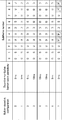
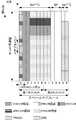
- FIG. 3 is a table showing an example of a subframe configuration in the radio frame of the present embodiment.
- the configuration of a subframe in a radio frame is referred to as “uplink-downlink configuration”.
- FIG. 3 shows eight uplink-downlink configurations.
- D indicates a downlink subframe
- U indicates an uplink subframe
- S indicates a special subframe
- F indicates a flexible subframe.
- the wireless communication system of this embodiment supports 5 ms and 10 ms downlink-to-uplink switch-point periodity.
- the downlink-to-uplink switch-point periodity is 5 ms
- a special subframe is included in both half frames in the radio frame.
- the downlink-to-uplink switch-point periodity is 10 ms
- the special subframe is included only in the first half frame in the radio frame.
- Subframes 0 and 5 and DwPTS are always reserved for downlink transmission.
- the subframe immediately after the special subframe and the UpPTS are always reserved for uplink transmission.
- the flexible subframe can be set only in subframes 3, 4, 8, and 9 in the radio frame.
- the base station apparatus 3 notifies the mobile station apparatus 1 of information indicating the configuration of special subframes (lengths of DwPTS, GP, and UpPTS) and information indicating the uplink-downlink configuration. For example, the base station apparatus 3 transmits a system information block including the information using PDSCH.
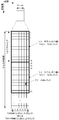
- FIG. 4 is a diagram showing the configuration of the slot according to the present embodiment.
- the physical signal or physical channel transmitted in each of the slots is represented by a resource grid.
- the resource grid is defined by a plurality of subcarriers and a plurality of OFDM symbols.
- the resource grid is defined by a plurality of subcarriers and a plurality of SC-FDMA symbols.
- the number of subcarriers constituting one slot depends on the cell bandwidth.
- the number of OFDM symbols or SC-FDMA symbols constituting one slot is seven.
- Each element in the resource grid is referred to as a resource element.
- the resource element is identified using a subcarrier number and an OFDM symbol or SC-FDMA symbol number.
- the resource block is used to express a mapping of resource elements of a certain physical channel (PDSCH or PUSCH).
- resource blocks virtual resource blocks and physical resource blocks are defined.
- a physical channel is first mapped to a virtual resource block. Thereafter, the virtual resource block is mapped to the physical resource block.
- One physical resource block is defined by 7 consecutive OFDM symbols or SC-FDMA symbols in the time domain and 12 consecutive subcarriers in the frequency domain. Therefore, one physical resource block is composed of (7 ⁇ 12) resource elements.
- One physical resource block corresponds to one slot in the time domain and corresponds to 180 kHz in the frequency domain. Physical resource blocks are numbered from 0 in the frequency domain.
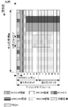
- FIG. 5 is a diagram illustrating an example of the arrangement of physical channels and physical signals in the downlink subframe according to the present embodiment.
- the base station apparatus 3 can transmit a downlink physical channel (PBCH, PCFICH, PHICH, PDCCH, ePDCCH, PDSCH) and a downlink physical signal (synchronization signal, downlink reference signal) in the downlink subframe.
- PBCH downlink physical channel
- PHICH PHICH
- PDCCH ePDCCH
- PDSCH downlink physical signal
- synchronization signal synchronization signal
- the downlink reference signal is arranged in resource elements distributed in the frequency domain and the time domain. For simplicity of explanation, the downlink reference signal is not shown in FIG.
- a plurality of PDCCHs are frequency and time multiplexed.
- a plurality of ePDCCHs are frequency, time and space multiplexed.
- a plurality of PDSCHs are frequency and space multiplexed.
- the PDCCH and PDSCH or ePDCCH are time multiplexed.
- the PDSCH and ePDCCH are frequency multiplexed.
- the base station apparatus 3 transmits the PDCCH (uplink grant) related to the PUSCH of the uplink subframe or the flexible subframe only in the downlink subframe. Moreover, the base station apparatus 3 transmits PHICH (ACK / NACK) regarding PUSCH of an uplink subframe or a flexible subframe only in a downlink subframe.
- PDCCH uplink grant
- PHICH ACK / NACK
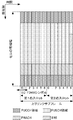
- FIG. 6 is a diagram illustrating an example of the arrangement of physical channels and physical signals in the uplink subframe of the present embodiment.
- the mobile station apparatus 1 can transmit an uplink physical channel (PUCCH, PUSCH, PRACH) and an uplink physical signal (DMRS, SRS) in the uplink subframe.
- PUCCH uplink physical channel
- PUSCH uplink physical signal
- DMRS uplink physical signal
- SRS uplink physical signal
- PUCCH region a plurality of PUCCHs are frequency, time, and code multiplexed.
- PUSCH region a plurality of PUSCHs are frequency and space multiplexed.
- PUCCH and PUSCH are frequency multiplexed.
- the PRACH is arranged over a single subframe or two subframes. A plurality of PRACHs are code-multiplexed.
- SRS is transmitted using the last SC-FDMA symbol in the uplink subframe. That is, the SRS is arranged in the last SC-FDMA symbol in the uplink subframe.
- the mobile station apparatus 1 cannot transmit SRS and PUCCH / PUSCH / PRACH simultaneously within a single cell.
- the mobile station apparatus 1 transmits PUSCH and / or PUCCH using an SC-FDMA symbol excluding the last SC-FDMA symbol in the uplink subframe.
- the SRS can be transmitted using the last SC-FDMA symbol in the uplink subframe. That is, in a single uplink subframe of a single cell, the mobile station apparatus 1 can transmit both SRS and PUSCH / PUCCH.
- DMRS is time-multiplexed with PUCCH or PUSCH. For simplicity of explanation, DMRS is not shown in FIG.
- FIG. 7 is a diagram showing an example of the arrangement of physical channels and physical signals in the special subframe of the present embodiment.
- DwPTS is composed of the first to ninth SC-FDMA symbols in the special subframe
- GP is composed of the tenth to twelfth SC-FDMA symbols in the special subframe
- UpPTS is the special subframe. It consists of the 13th and 14th SC-FDMA symbols in the frame.
- the base station apparatus 3 can transmit PCFICH, PHICH, PDCCH, ePDCCH, PDSCH, and a downlink reference signal in DwPTS of a special subframe.
- the base station apparatus 3 does not transmit the PBCH and the synchronization signal in the DwPTS of the special subframe.
- the mobile station apparatus 1 can transmit PRACH and SRS in the UpPTS of the special subframe. That is, the mobile station apparatus 1 does not transmit PUCCH, PUSCH, and DMRS in the UpPTS of the special subframe.
- the base station apparatus 3 can transmit at least ePDCCH and PDSCH in the flexible subframe. Moreover, the base station apparatus 3 may transmit PCFICH and PDCCH in a flexible subframe. Base station apparatus 3 does not transmit the PBCH and the synchronization signal in the flexible subframe.
- the mobile station apparatus 1 can transmit PUSCH, DMRS, and SRS in a flexible subframe. That is, the mobile station apparatus 1 does not transmit PRACH and PUCCH in the flexible subframe.
- the mobile station apparatus 1 regards the flexible subframe as a downlink subframe or an uplink subframe depending on whether transmission of PUSCH and / or SRS is scheduled in the flexible subframe. That is, the mobile station apparatus 1 performs a downlink physical channel and / or downlink physical signal reception process in the flexible subframe, depending on whether PUSCH and / or SRS transmission is scheduled in the flexible subframe. Or whether to perform transmission processing of an uplink physical channel and / or an uplink physical signal.
- the mobile station apparatus 1 When the mobile station apparatus 1 is scheduled to transmit PUSCH and SRS in a flexible subframe, the mobile station apparatus 1 transmits PUSCH and SRS in the flexible subframe, and receives downlink control information reception processing (monitoring) via the PDCCH and / or ePDCCH. ) Is not performed. When the mobile station apparatus 1 is scheduled to transmit PUSCH and SRS in a flexible subframe, the mobile station apparatus 1 regards the flexible subframe as an uplink subframe.
- the mobile station apparatus 1 When the mobile station apparatus 1 is not scheduled to transmit SRS in the flexible subframe and is scheduled to transmit PUSCH, the mobile station apparatus 1 transmits PUSCH in the flexible subframe, and receives downlink control information via the PDCCH and / or ePDCCH. Processing (monitoring) is not performed. When the mobile station apparatus 1 is not scheduled to transmit SRS in the flexible subframe and is scheduled to transmit PUSCH, the mobile station apparatus 1 regards the flexible subframe as an uplink subframe.
- the mobile station apparatus 1 When the mobile station apparatus 1 is not scheduled to transmit PUSCH in the flexible subframe and is scheduled to transmit SRS, the mobile station apparatus 1 transmits the SRS in the flexible subframe and receives downlink control information via the PDCCH and / or ePDCCH. Processing (monitoring) is not performed. When the mobile station apparatus 1 is not scheduled to transmit PUSCH in the flexible subframe and is scheduled to transmit SRS, the mobile station apparatus 1 regards the flexible subframe as an uplink subframe.
- the mobile station apparatus 1 performs at least downlink grant reception processing (monitoring) via the PDCCH and / or ePDCCH.
- the mobile station apparatus 1 detects the downlink grant in the flexible subframe
- the mobile station apparatus 1 performs PDSCH reception processing according to the detected downlink grant in the flexible subframe.
- the mobile station apparatus 1 regards the flexible subframe as a downlink subframe.
- a case where transmission of PUSCH or SRS is scheduled in a flexible subframe is a case where information for scheduling PUSCH of the flexible subframe is detected (received) in a downlink subframe before the flexible subframe.
- the mobile station apparatus 1 when the mobile station apparatus 1 is scheduled to transmit SRS without being scheduled to transmit PUSCH in the flexible subframe, the mobile station apparatus 1 transmits SRS in the flexible subframe and does not perform ePDCCH reception processing (monitor). You may perform reception processing (monitor) of downlink control information (for example, DCI format 3) other than a downlink grant using PDCCH. Since PDCCH is arranged from the first symbol of the flexible subframe and SRS is arranged at the last symbol of the flexible subframe, a symbol in which PDCCH and SRS are not arranged functions as a GP.
- ePDCCH reception processing for example, DCI format 3
- the mobile station apparatus 1 uses the flexible subframe to be reserved for uplink transmission and downlink transmission. May be regarded as a subframe including a field to be reserved.
- the mobile station apparatus 1 does not require a GP to switch from the uplink transmission process to the downlink reception process.
- the mobile station apparatus 1 uses the GP of the special subframe to switch from the downlink reception process to the uplink transmission process.
- the mobile station apparatus 1 can switch the PDSCH reception process and the PUSCH transmission process without limitation in the flexible subframe.
- a situation occurs in which the mobile station apparatus 1 attempts to perform PDSCH reception processing in the flexible subframe immediately before the uplink subframe or flexible subframe in which PUSCH transmission processing is performed, even though there is no GP. End up. That is, the mobile station apparatus 1 is required to simultaneously perform PDSCH reception processing and PUSCH transmission processing at the same frequency and the same timing, but such processing is impossible.
- the subframe immediately before the flexible subframe is an uplink subframe or a flexible subframe.
- the mobile station apparatus 1 can normally perform the uplink transmission process or the downlink reception process in the flexible subframe immediately after performing the uplink transmission process in the uplink subframe.
- the subframe immediately after the flexible subframe is a flexible subframe or a downlink subframe.
- the mobile station apparatus 1 receives the downlink reception in the downlink subframe immediately after performing the uplink transmission process or the downlink reception process in the flexible subframe. Processing can be performed normally.
- the mobile station apparatus 1 cannot perform the PUSCH transmission process in the flexible subframe immediately after the flexible subframe performing the PDSCH and / or ePDCCH reception process. There is a problem.
- FIG. 8 is a diagram showing an example of transmission / reception processing in the first embodiment of the present invention.
- the mobile station apparatus 1 receives PDSCH in the first flexible subframe, and transmits PUSCH in the second flexible subframe immediately after the first flexible subframe.
- the mobile station apparatus 1 creates a GP by not receiving at least a part of the first flexible subframe immediately before the second flexible subframe scheduled for PUSCH. For example, the mobile station apparatus 1 creates a GP by not receiving the last part or the latter half part of the first flexible subframe immediately before the second flexible subframe scheduled for at least PUSCH.
- the length of the generated GP may be determined by the mobile station apparatus 1 based on the configuration of the special subframe (GP length). That is, the mobile station apparatus 1 receives a part of the downlink signals (PDCCH and ePDCCH and downlink reference signal) in at least the first flexible subframe immediately before the second flexible subframe scheduled for PUSCH. It does not have to be. That is, the mobile station apparatus 1 excludes the last part (part necessary for generating GP) in the time domain in the first flexible subframe immediately before the second flexible subframe scheduled for PUSCH. Receive physical downlink shared channel.
- GP length the configuration of the special subframe
- the mobile station apparatus 1 when the mobile station apparatus 1 does not schedule PUSCH and SRS in the first flexible subframe, and at least PUSCH is scheduled in the second flexible subframe immediately after the first flexible subframe, (1) Monitor a downlink grant used for PDSCH scheduling in the first flexible subframe, (2) In the first flexible subframe, the PDSCH excluding the last part in the time domain is received based on the detected downlink grant.
- the mobile station apparatus 1 is used for the PUSCH and / or SRS schedule in the first flexible subframe and the second flexible subframe in the downlink subframe before the first flexible subframe.
- Information eg, uplink grant
- FIG. 9 is another diagram showing an example of transmission / reception processing in the first embodiment of the present invention. Since the SRS is transmitted only in the last (14th) SC-FDMA symbol of the subframe, the period of the first to thirteenth SC-FDMA symbols is GP in the flexible subframe in which only the SRS is scheduled. Therefore, the mobile station device 1 does not need to create a GP by not receiving the last part of the first flexible subframe immediately before the second flexible subframe scheduled for only SRS. That is, the mobile station apparatus 1 can receive all of the downlink signals (PDCCH, ePDCCH, and downlink reference signal) in the flexible subframe immediately before the flexible subframe in which only SRS is scheduled.
- the downlink signals PDCCH, ePDCCH, and downlink reference signal
- the mobile station apparatus 1 when the mobile station apparatus 1 performs the uplink transmission process in the flexible subframe, the mobile station apparatus 1 responds to the uplink physical channel and / or the uplink physical signal transmitted in the second flexible subframe that performs the uplink transmission process. It is determined whether to create a GP by not receiving the last part of the first flexible subframe immediately before the second flexible subframe performing the uplink transmission processing.
- the mobile station apparatus 1 is not required to simultaneously perform uplink transmission processing and downlink reception processing at a certain timing of the same frequency. Moreover, the mobile station apparatus 1 and the base station apparatus 3 can communicate efficiently using a flexible sub-frame.
- the mobile station apparatus 1 does not receive ePDCCH but receives PDCCH in at least a subframe immediately before the flexible subframe in which PUSCH is scheduled.
- the mobile station apparatus 1 does not monitor (monitor) the downlink grant on the PDCCH of the subframe immediately before the flexible subframe in which the PUSCH is scheduled.
- the mobile station apparatus 1 monitors (monitors) downlink control information (for example, DCI format 3) other than the downlink grant on at least the PDCCH of the subframe immediately before the flexible subframe scheduled for PUSCH.
- the mobile station apparatus 1 does not need to receive PDCCH in the sub-frame immediately before the flexible sub-frame by which PUSCH was scheduled.
- the mobile station apparatus 1 does not receive the PDSCH according to the downlink grant in at least the subframe immediately before the flexible subframe in which the PUSCH is scheduled.
- the mobile station apparatus 1 may not receive the PDSCH according to the downlink grant.
- the mobile station apparatus 1 when at least a PUSCH is scheduled in a certain flexible subframe, the mobile station apparatus 1 does not receive the PDCCH and the ePDCCH in the flexible subframe in which at least the PUSCH is scheduled, and the flexible subframe in which at least the PUSCH is scheduled. In the flexible subframe immediately before the frame, ePDCCH is not received but PDCCH is received.
- the mobile station apparatus 1 when at least PUSCH is scheduled in a certain flexible subframe, the mobile station apparatus 1 has a flexible subframe in which at least the PUSCH is scheduled, and a flexible subframe immediately before the flexible subframe in which the at least PUSCH is scheduled. Does not monitor the downlink grant.
- the mobile station apparatus 1 may receive PDCCH and / or ePDCCH in the flexible subframe immediately before the flexible subframe in which only SRS is scheduled. Moreover, the mobile station apparatus 1 may monitor (monitor) a downlink grant with PDCCH and / or ePDCCH of the flexible sub-frame immediately before the flexible sub-frame where only SRS was scheduled.
- the mobile station apparatus 1 when performing the uplink transmission process in the flexible subframe, performs the uplink according to the uplink physical channel and / or the uplink physical signal transmitted in the flexible subframe performing the uplink transmission process. In the flexible subframe immediately before the flexible subframe performing the transmission process, it is determined whether to receive ePDCCH and whether to monitor the downlink grant on PDCCH.
- the mobile station apparatus 1 does not schedule PUSCH and SRS in the first flexible subframe, and at least the PUSCH is scheduled in the second flexible subframe immediately after the first flexible subframe.
- the downlink grant used for PDSCH scheduling is not monitored in the first flexible subframe and the second flexible subframe.
- the mobile station apparatus 1 does not perform ePDCCH and PDSCH reception processing in at least the flexible subframe immediately before the flexible subframe in which the PUSCH is scheduled. Moreover, the mobile station apparatus 1 and the base station apparatus 3 can communicate efficiently using a flexible sub-frame.
- the mobile station apparatus 1 regards a flexible subframe scheduled for PUSCH and / or SRS as an uplink subframe. Moreover, the mobile station apparatus 1 considers the flexible subframe before the flexible subframe by which PUSCH and / or SRS were scheduled among continuous flexible subframes as an uplink subframe. That is, the mobile station apparatus 1 considers the continuous flexible subframe before the flexible subframe where PUSCH was scheduled last among the continuous flexible subframes as an uplink subframe. The mobile station apparatus 1 considers the flexible subframe after the last flexible subframe where PUSCH and / or SRS were scheduled among downlink flexible subframes as a downlink subframe. When PUSCH and / or SRS are not scheduled in any of the continuous flexible subframes, the mobile station apparatus 1 regards all of the continuous flexible subframes as downlink subframes.
- the mobile station apparatus 1 does not perform the downlink reception process in the flexible subframe that is regarded as the uplink subframe. That is, the mobile station apparatus 1 does not receive the downlink physical channel and the downlink physical signal in the flexible subframe regarded as the uplink subframe. That is, the mobile station apparatus 1 does not monitor (monitor) the downlink grant in the flexible subframe that is regarded as the uplink subframe.
- the mobile station apparatus 1 receives a downlink physical channel and a downlink physical signal in a flexible subframe that is regarded as a downlink subframe. For example, when the PDSCH resource is set in the flexible subframe regarded as the downlink subframe, the mobile station apparatus 1 receives the PDSCH. For example, the mobile station apparatus 1 monitors (monitors) a downlink grant in a flexible subframe that is regarded as a downlink subframe, and receives PDSCH in the flexible subframe based on the detected downlink grant. .
- a downlink grant monitor used for scheduling a downlink physical channel in a flexible subframe in which an uplink physical channel and / or an uplink physical signal are scheduled Without doing (2) A downlink physical channel schedule in a flexible subframe prior to the flexible subframe in which the uplink physical channel and / or the uplink physical signal are scheduled among the consecutive subframes.
- the mobile station device 1 when the uplink physical channel and the uplink physical signal are not scheduled in any of the continuous flexible subframes, Are all regarded as downlink subframes.
- FIG. 10 is a diagram showing a first example relating to the third embodiment of the present invention.
- the horizontal axis is the time domain.
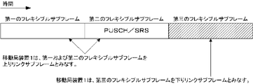
- FIG. 10 shows three subframes (first, second, and third flexible subframes) that are continuous in the time domain.
- PUSCH and SRS are not scheduled in the first and second flexible subframes, and PUSCH and / or SRS are scheduled in the third flexible subframe.
- the mobile station apparatus 1 regards the third flexible subframe scheduled for PUSCH and / or SRS as an uplink subframe. In FIG. 10, the mobile station apparatus 1 regards the first and second flexible subframes before the third flexible subframe scheduled for PUSCH and / or SRS as uplink subframes.
- FIG. 11 is a diagram showing a second example relating to the third embodiment of the present invention.
- the horizontal axis is the time domain.
- FIG. 11 shows three subframes (first, second, and third flexible subframes) that are continuous in the time domain.
- PUSCH and SRS are not scheduled in the second flexible subframe, and PUSCH and / or SRS are scheduled in the first and third flexible subframes.
- the mobile station apparatus 1 regards the first and third flexible subframes scheduled for PUSCH and / or SRS as uplink subframes. Also, in FIG. 11, the mobile station apparatus 1 regards the second flexible subframe before the third flexible subframe scheduled for PUSCH and / or SRS as the uplink subframe.
- FIG. 12 is a diagram showing a third example relating to the third embodiment of the present invention.
- the horizontal axis is the time domain.
- FIG. 12 shows three subframes (first, second, and third flexible subframes) that are continuous in the time domain.
- PUSCH and SRS are not scheduled in the first and third flexible subframes, and PUSCH and / or SRS are scheduled in the second flexible subframe.
- the mobile station apparatus 1 regards the second flexible subframe scheduled for PUSCH and / or SRS as an uplink subframe. In FIG. 12, the mobile station apparatus 1 regards the first flexible subframe prior to the second flexible subframe scheduled for PUSCH and / or SRS as the uplink subframe. In FIG. 12, the mobile station apparatus 1 regards the first flexible subframe after the second flexible subframe scheduled for PUSCH and / or SRS as the downlink subframe.
- FIG. 13 is a diagram showing a fourth example relating to the third embodiment of the present invention.
- the horizontal axis is the time domain.
- FIG. 13 shows three subframes (first, second, and third flexible subframes) that are continuous in the time domain.
- the mobile station apparatus 1 does not schedule PUSCH and SRS in any of the first, second, and third flexible subframes.
- the mobile station apparatus 1 regards all of the first, second, and third flexible subframes as downlink subframes.
- the mobile station apparatus 1 may regard the flexible subframe immediately before the flexible subframe scheduled for PUSCH as an uplink subframe.
- the third embodiment is not applied. For example, if the first flexible subframe is continuous with the second flexible subframe and the third flexible subframe is not continuous with any flexible subframe, the first flexible subframe and the first flexible subframe Although the third embodiment is applied to the second flexible subframe, the third embodiment is not applied to the third flexible subframe.
- the mobile station apparatus 1 does not consider a continuous flexible subframe before a flexible subframe regarded as an uplink subframe among the continuous flexible subframes as a downlink subframe. Therefore, the mobile station apparatus 1 does not switch from the downlink reception process to the uplink transmission process even if it switches from the uplink transmission process to the downlink reception process in successive flexible subframes. Moreover, the mobile station apparatus 1 and the base station apparatus 3 can communicate efficiently using a flexible sub-frame.
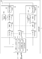
- FIG. 14 is a schematic block diagram showing the configuration of the mobile station apparatus 1 of the present embodiment.
- the mobile station apparatus 1 includes an upper layer processing unit 101, a control unit 103, a receiving unit 105, a transmitting unit 107, and a transmission / reception antenna 109.
- the upper layer processing unit 101 includes a radio resource control unit 1011, a scheduling information interpretation unit 1013, and a subframe control unit 1015.
- the reception unit 105 includes a decoding unit 1051, a demodulation unit 1053, a demultiplexing unit 1055, a radio reception unit 1057, and a channel measurement unit 1059.
- the transmission unit 107 includes an encoding unit 1071, a modulation unit 1073, a multiplexing unit 1075, a radio transmission unit 1077, and an uplink reference signal generation unit 1079.
- the upper layer processing unit 101 outputs uplink data (transport block) generated by a user operation or the like to the transmission unit 107.
- the upper layer processing unit 101 includes a medium access control (MAC: Medium Access Control) layer, a packet data integration protocol (Packet Data Convergence Protocol: PDCP) layer, a radio link control (Radio Link Control: RLC) layer, and radio resource control. Process the (Radio Resource Control: RRC) layer.
- MAC Medium Access Control
- PDCP Packet Data Convergence Protocol
- RLC Radio Link Control
- RRC Radio Resource Control
- the radio resource control unit 1011 included in the upper layer processing unit 101 manages various setting information of the own device.
- the radio resource control unit 1011 manages the uplink-downlink configuration. Also, the radio resource control unit 1011 generates information arranged in each uplink channel and outputs the information to the transmission unit 107.
- the scheduling information interpretation unit 1013 included in the upper layer processing unit 101 interprets information used for scheduling of a physical channel (PUSCH, PDSCH, etc.) received via the reception unit 105, and based on the result of interpreting the information, Control information is generated to control the reception unit 105 and the transmission unit 107 and output to the control unit 103.
- PUSCH physical channel
- PDSCH physical channel
- the subframe control unit 1015 included in the higher layer processing unit 101 determines whether to perform downlink reception processing or uplink transmission processing in the flexible subframe. Also, the subframe control unit 1015 determines whether to perform PDCCH and / or ePDCCH reception processing in the flexible subframe. Also, the subframe control unit 1015 determines whether or not to monitor the downlink grant on the PDCCH and / or ePDCCH in the flexible subframe.
- the control unit 103 generates a control signal for controlling the receiving unit 105 and the transmitting unit 107 based on the control information from the higher layer processing unit 101. Control unit 103 outputs the generated control signal to receiving unit 105 and transmitting unit 107 to control receiving unit 105 and transmitting unit 107.
- the receiving unit 105 separates, demodulates, and decodes the received signal received from the base station apparatus 3 via the transmission / reception antenna 109 according to the control signal input from the control unit 103, and sends the decoded information to the upper layer processing unit 101. Output.
- the radio reception unit 1057 converts the downlink signal received via the transmission / reception antenna 109 into an intermediate frequency (down-conversion: down covert), removes unnecessary frequency components, and maintains the signal level appropriately. Then, the amplification level is controlled, quadrature demodulation is performed based on the in-phase component and the quadrature component of the received signal, and the quadrature demodulated analog signal is converted into a digital signal.
- the radio reception unit 1057 removes a portion corresponding to a guard interval (Guard Interval: GI) from the converted digital signal, and performs a fast Fourier transform (FFT Fourier Transform: FFT) on the signal from which the guard interval has been removed. Extract the region signal.
- GI Guard Interval
- FFT fast Fourier transform
- the demultiplexing unit 1055 separates the extracted signal into PHICH, PDCCH, ePDCCH, PDSCH, and downlink reference signal. Further, demultiplexing section 1055 compensates the propagation path of PHICH, PDCCH, and PDSCH from the estimated propagation path value input from channel measurement section 1059. Also, the demultiplexing unit 1055 outputs the demultiplexed downlink reference signal to the channel measurement unit 1059.
- the demodulating unit 1053 multiplies the PHICH by a corresponding code and synthesizes the signal, demodulates the synthesized signal using a BPSK (Binary Phase Shift Shift Keying) modulation method, and outputs the demodulated signal to the decoding unit 1051.
- Decoding section 1051 decodes the PHICH addressed to the own apparatus, and outputs the decoded HARQ indicator to higher layer processing section 101.
- Demodulation section 1053 performs QPSK modulation demodulation on PDCCH and / or ePDCCH, and outputs the result to decoding section 1051.
- Decoding section 1051 attempts blind decoding of PDCCH and / or ePDCCH, and when blind decoding is successful, decoded downlink control information and RNTI included in downlink control information are sent to higher layer processing section 101. Output.
- the demodulation unit 1053 demodulates the modulation scheme notified by the downlink grant such as QPSK (Quadrature Shift Keying), 16QAM (Quadrature Amplitude Modulation), 64QAM, and the like to the decoding unit 1051.
- the decoding unit 1051 performs decoding based on the information regarding the coding rate notified by the downlink control information, and outputs the decoded downlink data (transport block) to the higher layer processing unit 101.
- the channel measurement unit 1059 measures the downlink path loss and channel state from the downlink reference signal input from the demultiplexing unit 1055, and outputs the measured path loss and channel state to the upper layer processing unit 101. Also, channel measurement section 1059 calculates an estimated value of the downlink propagation path from the downlink reference signal, and outputs it to demultiplexing section 1055.
- the transmission unit 107 generates an uplink reference signal according to the control signal input from the control unit 103, encodes and modulates the uplink data (transport block) input from the higher layer processing unit 101, PUCCH, The PUSCH and the generated uplink reference signal are multiplexed and transmitted to the base station apparatus 3 via the transmission / reception antenna 109.
- the encoding unit 1071 performs encoding such as convolutional encoding and block encoding on the uplink control information input from the higher layer processing unit 101.
- the encoding unit 1071 performs turbo encoding based on information used for PUSCH scheduling.
- the modulation unit 1073 modulates the coded bits input from the coding unit 1071 using a modulation method notified by downlink control information such as BPSK, QPSK, 16QAM, 64QAM, or a modulation method predetermined for each channel.
- Modulation section 1073 determines the number of spatially multiplexed data sequences based on information used for PUSCH scheduling, and uses MIMO SM to transmit a plurality of uplink data transmitted on the same PUSCH to a plurality of uplink data. Mapping to a sequence and precoding the sequence.
- the uplink reference signal generation unit 1079 is a physical cell identifier for identifying the base station device 3 (referred to as physical cell ⁇ ⁇ identity: ⁇ ⁇ ⁇ PCI, Cell ⁇ ID, etc.), a bandwidth for arranging the uplink reference signal, and an uplink grant. Based on the notified cyclic shift, the value of the parameter for generating the DMRS sequence, etc., a sequence determined by a predetermined rule is generated.
- the multiplexing unit 1075 rearranges the PUSCH modulation symbols in parallel according to the control signal input from the control unit 103, and then performs a discrete Fourier transform (Discrete-Fourier-Transform: DFT).
- DFT discrete Fourier transform
- multiplexing section 1075 multiplexes the PUCCH and PUSCH signals and the generated uplink reference signal for each transmission antenna port. That is, multiplexing section 1075 arranges the PUCCH and PUSCH signals and the generated uplink reference signal in the resource element for each transmission antenna port.
- Radio transmission section 1077 performs inverse fast Fourier transform (inverse Fast Transform: IFFT) on the multiplexed signal, performs SC-FDMA modulation, and adds a guard interval to the SC-FDMA-modulated SC-FDMA symbol
- IFFT inverse Fast Transform
- a baseband digital signal converting the baseband digital signal to an analog signal, generating an in-phase component and a quadrature component of an intermediate frequency from the analog signal, removing an extra frequency component for the intermediate frequency band,
- the intermediate frequency signal is converted to a high frequency signal (up-conversion: up convert), an extra frequency component is removed, the power is amplified, and output to the transmission / reception antenna 109 for transmission.
- FIG. 15 is a schematic block diagram showing the configuration of the base station apparatus 3 of the present embodiment.
- the base station apparatus 3 includes an upper layer processing unit 301, a control unit 303, a reception unit 305, a transmission unit 307, and a transmission / reception antenna 309.
- the upper layer processing unit 301 includes a radio resource control unit 3011, a scheduling unit 3013, and a control information generation unit 3015.
- the reception unit 305 includes a decoding unit 3051, a demodulation unit 3053, a demultiplexing unit 3055, a wireless reception unit 3057, and a channel measurement unit 3059.
- the transmission unit 307 includes an encoding unit 3071, a modulation unit 3073, a multiplexing unit 3075, a radio transmission unit 3077, and a downlink reference signal generation unit 3079.
- the upper layer processing unit 301 includes a medium access control (MAC: Medium Access Control) layer, a packet data integration protocol (Packet Data Convergence Protocol: PDCP) layer, a radio link control (Radio Link Control: RLC) layer, a radio resource control (Radio). Resource (Control: RRC) layer processing. Further, upper layer processing section 301 generates control information for controlling receiving section 305 and transmitting section 307 and outputs the control information to control section 303.
- MAC Medium Access Control
- PDCP Packet Data Convergence Protocol
- RLC Radio Link Control
- Radio Radio Resource
- the radio resource control unit 3011 provided in the upper layer processing unit 301 generates downlink data (transport block), RRC signal, MAC CE (Control Element) arranged in the downlink PDSCH, or acquires it from the upper node. And output to the transmission unit 307. Further, the radio resource control unit 3011 manages various setting information of each mobile station apparatus 1. The radio resource control unit 3011 manages the uplink-downlink configuration of each mobile station apparatus 1.
- the scheduling unit 3013 included in the higher layer processing unit 301 assigns the physical channel (PDSCH and PUSCH) to the frequency, subframe, and physical channel (PDSCH) based on the channel estimation value and the channel quality input from the channel measurement unit 3059. And the PUSCH) coding rate, modulation scheme, transmission power, and the like.
- the scheduling unit 3013 determines whether to schedule a downlink physical channel and / or a downlink physical signal or schedule an uplink physical channel and / or an uplink physical signal in a flexible subframe. Based on the scheduling result, scheduling section 3013 generates control information for controlling receiving section 305 and transmitting section 307 and outputs the control information to control section 303. In addition, the scheduling unit 3013 outputs the scheduling results of the physical channels (PDSCH and PUSCH) to the control information generation unit 3015.
- the control information generation unit 3015 generates information used for scheduling of physical channels (PDSCH and PUSCH) based on the scheduling result input from the scheduling unit 3013. In addition, the control information generation unit 3015 generates a handover command and the like. Further, the control information generation unit 3015 outputs the generated information to the transmission unit 307.
- the control unit 303 generates a control signal for controlling the reception unit 305 and the transmission unit 307 based on the control information from the higher layer processing unit 301.
- the control unit 303 outputs the generated control signal to the reception unit 305 and the transmission unit 307 and controls the reception unit 305 and the transmission unit 307.
- the receiving unit 305 separates, demodulates and decodes the received signal received from the mobile station apparatus 1 via the transmission / reception antenna 309 according to the control signal input from the control unit 303, and outputs the decoded information to the higher layer processing unit 301.
- the radio reception unit 3057 converts an uplink signal received via the transmission / reception antenna 309 into an intermediate frequency (down-conversion: down covert), removes unnecessary frequency components, and appropriately maintains the signal level. In this way, the amplification level is controlled, and based on the in-phase and quadrature components of the received signal, quadrature demodulation is performed, and the quadrature demodulated analog signal is converted into a digital signal.
- the wireless receiver 3057 removes a portion corresponding to a guard interval (Guard Interval: GI) from the converted digital signal.
- the radio reception unit 3057 performs fast Fourier transform (FFT) on the signal from which the guard interval is removed, extracts a frequency domain signal, and outputs the signal to the demultiplexing unit 3055.
- FFT fast Fourier transform
- the demultiplexing unit 1055 demultiplexes the signal input from the radio receiving unit 3057 into signals such as PUCCH, PUSCH, and uplink reference signal. This separation is performed based on radio resource allocation information included in the uplink grant that is determined in advance by the radio resource control unit 3011 by the base station device 3 and notified to each mobile station device 1.
- demultiplexing section 3055 compensates for the propagation paths of PUCCH and PUSCH from the propagation path estimation value input from channel measurement section 3059. Further, the demultiplexing unit 3055 outputs the separated uplink reference signal to the channel measurement unit 3059.
- the demodulator 3053 performs inverse discrete Fourier transform (Inverse Discrete Fourier Transform: IDFT) on the PUSCH, acquires modulation symbols, and performs BPSK (Binary Shift Keying), QPSK, 16QAM, and PUCCH and PUSCH modulation symbols respectively.
- IDFT inverse discrete Fourier transform
- the received signal is demodulated using a predetermined modulation scheme such as 64QAM, or a modulation scheme that the own device has previously notified to each mobile station device 1 using an uplink grant.
- Demodulation section 3053 is the same by using MIMO SM based on the number of spatially multiplexed sequences notified in advance to each mobile station apparatus 1 using an uplink grant and information indicating precoding performed on these sequences.
- the modulation symbols of a plurality of uplink data transmitted on the PUSCH are separated.
- the decoding unit 3051 encodes the demodulated PUCCH and PUSCH encoded bits in a predetermined encoding method in advance or the mobile station apparatus 1 previously notified to the mobile station apparatus 1 using an uplink grant. Decoding is performed at a rate, and the decoded uplink data and uplink control information are output to the upper layer processing section 101. When PUSCH is retransmitted, decoding section 3051 performs decoding using the encoded bits held in the HARQ buffer input from higher layer processing section 301 and the demodulated encoded bits.
- Channel measurement section 309 measures an estimated channel value, channel quality, and the like from the uplink reference signal input from demultiplexing section 3055 and outputs the result to demultiplexing section 3055 and higher layer processing section 301.
- the transmission unit 307 generates a downlink reference signal according to the control signal input from the control unit 303, encodes and modulates the HARQ indicator, downlink control information, and downlink data input from the higher layer processing unit 301. Then, the PHICH, PDCCH, ePDCCH, PDSCH, and downlink reference signal are multiplexed, and the signal is transmitted to the mobile station apparatus 1 via the transmission / reception antenna 309.
- the encoding unit 3071 is a predetermined encoding method such as block encoding, convolutional encoding, turbo encoding, and the like for the HARQ indicator, downlink control information, and downlink data input from the higher layer processing unit 301 Or is encoded using the encoding method determined by the radio resource control unit 3011.
- the modulation unit 3073 modulates the coded bits input from the coding unit 3071 with a modulation scheme determined in advance by the radio resource control unit 3011 such as BPSK, QPSK, 16QAM, and 64QAM.
- the downlink reference signal generation unit 3079 uses, as a downlink reference signal, a sequence known by the mobile station apparatus 1 that is obtained by a predetermined rule based on a physical cell identifier (PCI) for identifying the base station apparatus 3 or the like. Generate.
- the multiplexing unit 3075 multiplexes the modulated modulation symbol of each channel and the generated downlink reference signal. That is, multiplexing section 3075 arranges the modulated modulation symbol of each channel and the generated downlink reference signal in the resource element.
- the wireless transmission unit 3077 performs inverse fast Fourier transform (Inverse Fast Fourier Transform: IFFT) on the multiplexed modulation symbols and the like, performs modulation in the OFDM scheme, adds a guard interval to the OFDM symbol that has been OFDM-modulated, and baseband
- IFFT inverse Fast Fourier Transform
- the baseband digital signal is converted to an analog signal, the in-phase and quadrature components of the intermediate frequency are generated from the analog signal, the extra frequency components for the intermediate frequency band are removed, and the intermediate-frequency signal is generated. Is converted to a high-frequency signal (up-conversion: up convert), an extra frequency component is removed, power is amplified, and output to the transmission / reception antenna 309 for transmission.
- a program that operates in the base station apparatus 3 and the mobile station apparatus 1 related to the present invention is a program (computer functions as a computer) that controls a CPU (Central Processing Unit) so as to realize the functions of the above-described embodiments related to the present invention.
- Program Information handled by these devices is temporarily stored in RAM (Random Access Memory) during processing, and then stored in various ROMs such as Flash ROM (Read Only Memory) and HDD (Hard Disk Drive). Reading, correction, and writing are performed by the CPU as necessary.
- the program for realizing the control function may be recorded on a computer-readable recording medium, and the program recorded on the recording medium may be read by the computer system and executed.
- the “computer system” here is a computer system built in the mobile station apparatus 1 or the base station apparatus 3, and includes an OS and hardware such as peripheral devices.
- the “computer-readable recording medium” refers to a storage device such as a flexible medium, a magneto-optical disk, a portable medium such as a ROM or a CD-ROM, and a hard disk incorporated in a computer system.
- the “computer-readable recording medium” is a medium that dynamically holds a program for a short time, such as a communication line when transmitting a program via a network such as the Internet or a communication line such as a telephone line,
- a volatile memory inside a computer system serving as a server or a client may be included and a program that holds a program for a certain period of time.
- the program may be a program for realizing a part of the functions described above, and may be a program capable of realizing the functions described above in combination with a program already recorded in a computer system.
- a part or all of the mobile station device 1 and the base station device 3 in the above-described embodiment may be realized as an LSI that is typically an integrated circuit, or may be realized as a chip set.
- Each functional block of the mobile station device 1 and the base station device 3 may be individually chipped, or a part or all of them may be integrated into a chip.
- the method of circuit integration is not limited to LSI, and may be realized by a dedicated circuit or a general-purpose processor.
- an integrated circuit based on the technology can also be used.
Landscapes
- Engineering & Computer Science (AREA)
- Signal Processing (AREA)
- Computer Networks & Wireless Communication (AREA)
- Mobile Radio Communication Systems (AREA)
Abstract
Selon la présente invention, un dispositif de station de base et un dispositif de station mobile communiquent efficacement l'un avec l'autre à l'aide d'une sous-trame flexible. Lorsqu'un canal partagé de liaison montante physique (PUSCH) et un signal de référence de sondage ne sont pas planifiés dans une première sous-trame flexible, et au moins le canal partagé de liaison montante physique est planifié dans une seconde sous-trame flexible immédiatement après la première sous-trame flexible, l'autorisation de liaison descendante utilisée dans la planification d'un canal partagé de liaison descendante physique (PDSCH) dans la première sous-trame flexible est surveillée dans le dispositif de station mobile, et le canal partagé de liaison descendante physique dont la partie finale dans le domaine temporel a été supprimée est reçu dans le dispositif de station mobile sur la base de l'autorisation de liaison descendante détectée dans la première sous-trame flexible.
Priority Applications (3)
| Application Number | Priority Date | Filing Date | Title |
|---|---|---|---|
| EP13809711.8A EP2869628B1 (fr) | 2012-06-27 | 2013-06-27 | Dispositif de station de base, dispositif de station mobile et procédé de communication sans fil pour traiter un bloc d'informations de système |
| US14/410,690 US9699780B2 (en) | 2012-06-27 | 2013-06-27 | Base station device, mobile station device, wireless communication method, integrated circuit, and wireless communication system |
| CN201380033616.2A CN104412645B (zh) | 2012-06-27 | 2013-06-27 | 基站装置、移动站装置以及无线通信方法 |
Applications Claiming Priority (2)
| Application Number | Priority Date | Filing Date | Title |
|---|---|---|---|
| JP2012-144084 | 2012-06-27 | ||
| JP2012144084A JP6131458B2 (ja) | 2012-06-27 | 2012-06-27 | 移動局装置、基地局装置、および無線通信方法 |
Publications (1)
| Publication Number | Publication Date |
|---|---|
| WO2014003104A1 true WO2014003104A1 (fr) | 2014-01-03 |
Family
ID=49783241
Family Applications (1)
| Application Number | Title | Priority Date | Filing Date |
|---|---|---|---|
| PCT/JP2013/067620 Ceased WO2014003104A1 (fr) | 2012-06-27 | 2013-06-27 | Dispositif de station de base, dispositif de station mobile, procédé de communication sans fil, circuit intégré et système de communication sans fil |
Country Status (5)
| Country | Link |
|---|---|
| US (1) | US9699780B2 (fr) |
| EP (1) | EP2869628B1 (fr) |
| JP (1) | JP6131458B2 (fr) |
| CN (1) | CN104412645B (fr) |
| WO (1) | WO2014003104A1 (fr) |
Cited By (11)
| Publication number | Priority date | Publication date | Assignee | Title |
|---|---|---|---|---|
| JP5739027B1 (ja) * | 2014-01-22 | 2015-06-24 | 株式会社Nttドコモ | ユーザ端末、無線基地局および無線通信方法 |
| WO2015108008A1 (fr) * | 2014-01-14 | 2015-07-23 | 株式会社Nttドコモ | Terminal d'utilisateur, station de base sans fil, et procédé de communication sans fil |
| WO2015108007A1 (fr) * | 2014-01-14 | 2015-07-23 | 株式会社Nttドコモ | Terminal d'utilisateur, station de base sans fil, et procédé de communication sans fil |
| WO2015115465A1 (fr) * | 2014-01-30 | 2015-08-06 | シャープ株式会社 | Dispositif de terminal, dispositif de station de base et procédé de communication |
| EP3249845A4 (fr) * | 2015-02-17 | 2018-03-07 | Huawei Technologies Co., Ltd. | Procédé de transmission d'informations, équipement utilisateur, et station de base |
| US11026245B2 (en) | 2015-03-15 | 2021-06-01 | Qualcomm Incorporated | Mission critical data support in self-contained time division duplex (TDD) subframe structure |
| US11057895B2 (en) | 2017-01-24 | 2021-07-06 | Huawei Technologies Co., Ltd. | Retuning method and apparatus for SRS coverage enhancement |
| US11122583B2 (en) | 2015-05-15 | 2021-09-14 | Qualcomm Incorporated | Scaled symbols for a self-contained time division duplex (TDD) subframe structure |
| US11470625B2 (en) | 2015-07-20 | 2022-10-11 | Qualcomm Incorporated | Time division duplex (TDD) subframe structure supporting single and multiple interlace modes |
| US11950241B2 (en) | 2015-03-15 | 2024-04-02 | Qualcomm Incorporated | Self-contained time division duplex (TDD) subframe structure for wireless communications |
| US11997656B2 (en) | 2015-03-15 | 2024-05-28 | Qualcomm Incorporated | Self-contained time division duplex (TDD) subframe structure |
Families Citing this family (10)
| Publication number | Priority date | Publication date | Assignee | Title |
|---|---|---|---|---|
| JP2015165640A (ja) * | 2014-02-07 | 2015-09-17 | 株式会社Nttドコモ | ユーザ装置、基地局、及び通信方法 |
| US10560891B2 (en) * | 2014-09-09 | 2020-02-11 | Blackberry Limited | Medium Access Control in LTE-U |
| JP2018050089A (ja) | 2015-01-29 | 2018-03-29 | シャープ株式会社 | 端末装置、基地局装置、集積回路、および、通信方法 |
| WO2016159673A1 (fr) * | 2015-04-03 | 2016-10-06 | 엘지전자 주식회사 | Procédé de réception d'un signal de liaison descendante via une bande sans licence dans un système de communication sans fil et dispositif associé |
| EP4239943A3 (fr) * | 2015-07-17 | 2023-10-25 | 5G SIG Co., Ltd. | Procédé d'attribution de ressources et dispositif de communication |
| US10356811B2 (en) * | 2016-01-28 | 2019-07-16 | Qualcomm Incorporated | Methods and apparatus for grant processing |
| ES2975459T3 (es) * | 2016-08-31 | 2024-07-05 | Ntt Docomo Inc | Terminal y método de comunicación por radio |
| CN110120860B (zh) * | 2018-02-06 | 2020-06-30 | 上海朗帛通信技术有限公司 | 一种被用于无线通信的用户设备、基站中的方法和装置 |
| CN110933761B (zh) * | 2018-09-20 | 2022-02-15 | 成都华为技术有限公司 | 资源调度方法及设备 |
| JP7526282B2 (ja) * | 2020-04-07 | 2024-07-31 | エルジー エレクトロニクス インコーポレイティド | 無線通信システムにおいてサウンディング参照信号送受信方法及び装置 |
Citations (1)
| Publication number | Priority date | Publication date | Assignee | Title |
|---|---|---|---|---|
| WO2011077288A2 (fr) * | 2009-12-23 | 2011-06-30 | Telefonaktiebolaget L M Ericsson (Publ) | Sous-trames flexibles |
Family Cites Families (8)
| Publication number | Priority date | Publication date | Assignee | Title |
|---|---|---|---|---|
| WO2010049587A1 (fr) | 2008-10-31 | 2010-05-06 | Nokia Corporation | Allocation dynamique de programmation de sous-trame pour un fonctionnement en duplexage par répartition dans le temps dans un système de communication sans fil à base de paquets |
| CN101902820B (zh) * | 2009-05-25 | 2013-04-03 | 电信科学技术研究院 | 一种发送上行数据的方法、系统和装置 |
| US9154260B2 (en) * | 2010-03-26 | 2015-10-06 | Qualcomm Incorporated | Method and apparatus for reliable transmission of control information in a wireless communication network |
| WO2012019348A1 (fr) * | 2010-08-12 | 2012-02-16 | Nokia Corporation | Configuration d'un schéma de division de liaison montante et de liaison descendante pour une communication entre dispositifs (d2d) dans un réseau cellulaire |
| JP5709884B2 (ja) | 2010-10-08 | 2015-04-30 | パナソニック インテレクチュアル プロパティ コーポレーション オブアメリカPanasonic Intellectual Property Corporation of America | 基地局、端末、送信方法、及び受信方法 |
| WO2012068731A1 (fr) * | 2010-11-25 | 2012-05-31 | Nokia Corporation | Détection assistée par réseau sur une bande partagée pour des communications locales |
| CN102271032B (zh) * | 2011-08-09 | 2014-11-19 | 电信科学技术研究院 | 一种实现上行反馈的方法、系统及装置 |
| US9143984B2 (en) * | 2012-04-13 | 2015-09-22 | Intel Corporation | Mapping of enhanced physical downlink control channels in a wireless communication network |
-
2012
- 2012-06-27 JP JP2012144084A patent/JP6131458B2/ja active Active
-
2013
- 2013-06-27 CN CN201380033616.2A patent/CN104412645B/zh active Active
- 2013-06-27 US US14/410,690 patent/US9699780B2/en active Active
- 2013-06-27 EP EP13809711.8A patent/EP2869628B1/fr active Active
- 2013-06-27 WO PCT/JP2013/067620 patent/WO2014003104A1/fr not_active Ceased
Patent Citations (1)
| Publication number | Priority date | Publication date | Assignee | Title |
|---|---|---|---|---|
| WO2011077288A2 (fr) * | 2009-12-23 | 2011-06-30 | Telefonaktiebolaget L M Ericsson (Publ) | Sous-trames flexibles |
Non-Patent Citations (6)
| Title |
|---|
| "On standardization impact of TDD UL-DL adaptation", RL-122016, 3GPP TSG-RAN WG1 MEETING #69, PRAGUE, CZECH REPUBLIC, 21 May 2012 (2012-05-21) |
| "Renesas Mobile Europe Ltd., Discussion on Enhancements for Dynamic TDD UL-DL Configuration", 3GPP TSG-RAN WG1 MEETING #69 R1-122363, 21 May 2012 (2012-05-21), XP050600626 * |
| CATT: "TP for TR36.828 section 7", 3GPP TSG RAN WG1 MEETING #69 R1-122948, 21 May 2012 (2012-05-21), XP050601307 * |
| SAMSUNG: "Dynamic reconfiguration of TDD UL-DL configuration", 3GPP TSG RAN WG1 MEETING #69 R1-122267, 21 May 2012 (2012-05-21), XP050600530 * |
| SAMSUNG: "Semi-static reconfiguration of TDD UL-DL configuration", 3GPP TSG RAN WG1 MEETING #69 R1-122266, 21 May 2012 (2012-05-21), XP050600529 * |
| See also references of EP2869628A4 |
Cited By (16)
| Publication number | Priority date | Publication date | Assignee | Title |
|---|---|---|---|---|
| WO2015108008A1 (fr) * | 2014-01-14 | 2015-07-23 | 株式会社Nttドコモ | Terminal d'utilisateur, station de base sans fil, et procédé de communication sans fil |
| WO2015108007A1 (fr) * | 2014-01-14 | 2015-07-23 | 株式会社Nttドコモ | Terminal d'utilisateur, station de base sans fil, et procédé de communication sans fil |
| JP5739027B1 (ja) * | 2014-01-22 | 2015-06-24 | 株式会社Nttドコモ | ユーザ端末、無線基地局および無線通信方法 |
| WO2015111484A1 (fr) * | 2014-01-22 | 2015-07-30 | 株式会社Nttドコモ | Terminal utilisateur, station de base sans fil et procédé de communication sans fil |
| WO2015115465A1 (fr) * | 2014-01-30 | 2015-08-06 | シャープ株式会社 | Dispositif de terminal, dispositif de station de base et procédé de communication |
| US10454630B2 (en) | 2015-02-17 | 2019-10-22 | Huawei Technologies Co., Ltd. | Information transmission method, and user equipment and base station |
| EP3249845A4 (fr) * | 2015-02-17 | 2018-03-07 | Huawei Technologies Co., Ltd. | Procédé de transmission d'informations, équipement utilisateur, et station de base |
| US11997656B2 (en) | 2015-03-15 | 2024-05-28 | Qualcomm Incorporated | Self-contained time division duplex (TDD) subframe structure |
| US11026245B2 (en) | 2015-03-15 | 2021-06-01 | Qualcomm Incorporated | Mission critical data support in self-contained time division duplex (TDD) subframe structure |
| US11622361B2 (en) | 2015-03-15 | 2023-04-04 | Qualcomm Incorporated | Mission critical data support in self-contained time division duplex (TDD) subframe structure |
| US12004129B2 (en) | 2015-03-15 | 2024-06-04 | Qualcomm Incorporated | Self-contained time division duplex (TDD) subframe structure |
| US11950241B2 (en) | 2015-03-15 | 2024-04-02 | Qualcomm Incorporated | Self-contained time division duplex (TDD) subframe structure for wireless communications |
| US11122583B2 (en) | 2015-05-15 | 2021-09-14 | Qualcomm Incorporated | Scaled symbols for a self-contained time division duplex (TDD) subframe structure |
| US11470625B2 (en) | 2015-07-20 | 2022-10-11 | Qualcomm Incorporated | Time division duplex (TDD) subframe structure supporting single and multiple interlace modes |
| US11057895B2 (en) | 2017-01-24 | 2021-07-06 | Huawei Technologies Co., Ltd. | Retuning method and apparatus for SRS coverage enhancement |
| US11632763B2 (en) | 2017-01-24 | 2023-04-18 | Huawei Technologies Co., Ltd. | Retuning method and apparatus |
Also Published As
| Publication number | Publication date |
|---|---|
| JP2014007710A (ja) | 2014-01-16 |
| JP6131458B2 (ja) | 2017-05-24 |
| EP2869628A1 (fr) | 2015-05-06 |
| US9699780B2 (en) | 2017-07-04 |
| US20150189648A1 (en) | 2015-07-02 |
| EP2869628B1 (fr) | 2019-08-07 |
| CN104412645B (zh) | 2018-04-27 |
| EP2869628A4 (fr) | 2015-09-02 |
| CN104412645A (zh) | 2015-03-11 |
Similar Documents
| Publication | Publication Date | Title |
|---|---|---|
| JP6131458B2 (ja) | 移動局装置、基地局装置、および無線通信方法 | |
| JP6041295B2 (ja) | 端末装置、基地局装置、および無線通信方法 | |
| JP6380956B2 (ja) | 端末装置、基地局装置、集積回路、および、通信方法 | |
| JP5941305B2 (ja) | 移動局装置、基地局装置、無線通信システム、無線通信方法および集積回路 | |
| JP6240976B2 (ja) | 端末装置、基地局装置、集積回路、および、通信方法 | |
| JP6452048B2 (ja) | 端末装置、基地局装置、通信方法、および、集積回路 | |
| JP6417599B2 (ja) | 端末装置、無線通信方法、および集積回路 | |
| KR20130111955A (ko) | 이동국 장치, 기지국 장치, 무선 통신 시스템, 무선 통신 방법 및 집적 회로 | |
| EP3113561B1 (fr) | Dispositif terminal, circuit intégré et procédé de communication sans fil | |
| WO2016002441A1 (fr) | Dispositif de station mobile et dispositif de station de base | |
| JP6507454B2 (ja) | 基地局装置、端末装置、および通信方法 | |
| JP6521863B2 (ja) | 端末装置、基地局装置、集積回路、および、通信方法 | |
| WO2015008830A1 (fr) | Dispositif de terminal, dispositif de station de base, circuit intégré et procédé de communication sans fil | |
| WO2014021394A1 (fr) | Dispositif de station mobile, dispositif de station de base, procédé de communication sans fil et circuit intégré | |
| WO2016163186A1 (fr) | Appareil terminal, appareil de station de base, circuit intégré et procédé de communication | |
| JP2012065126A (ja) | 無線通信システム、基地局装置、移動局装置、無線通信方法および集積回路 | |
| CN105075374B (zh) | 终端装置、基站装置、集成电路以及无线通信方法 | |
| JP6332643B2 (ja) | 端末装置、集積回路、および通信方法 | |
| JP2013135249A (ja) | 移動局装置、基地局装置、無線通信システム、無線通信方法および集積回路 |
Legal Events
| Date | Code | Title | Description |
|---|---|---|---|
| 121 | Ep: the epo has been informed by wipo that ep was designated in this application |
Ref document number: 13809711 Country of ref document: EP Kind code of ref document: A1 |
|
| WWE | Wipo information: entry into national phase |
Ref document number: 14410690 Country of ref document: US Ref document number: 2013809711 Country of ref document: EP |
|
| NENP | Non-entry into the national phase |
Ref country code: DE |