WO2014006733A1 - Système et procédé de réseau de sécurité numérique - Google Patents
Système et procédé de réseau de sécurité numérique Download PDFInfo
- Publication number
- WO2014006733A1 WO2014006733A1 PCT/JP2012/067242 JP2012067242W WO2014006733A1 WO 2014006733 A1 WO2014006733 A1 WO 2014006733A1 JP 2012067242 W JP2012067242 W JP 2012067242W WO 2014006733 A1 WO2014006733 A1 WO 2014006733A1
- Authority
- WO
- WIPO (PCT)
- Prior art keywords
- jurisdiction
- communication terminal
- emergency
- control unit
- terminal device
- Prior art date
- Legal status (The legal status is an assumption and is not a legal conclusion. Google has not performed a legal analysis and makes no representation as to the accuracy of the status listed.)
- Ceased
Links
Images



Classifications
-
- H—ELECTRICITY
- H04—ELECTRIC COMMUNICATION TECHNIQUE
- H04M—TELEPHONIC COMMUNICATION
- H04M11/00—Telephonic communication systems specially adapted for combination with other electrical systems
- H04M11/04—Telephonic communication systems specially adapted for combination with other electrical systems with alarm systems, e.g. fire, police or burglar alarm systems
-
- G—PHYSICS
- G08—SIGNALLING
- G08B—SIGNALLING SYSTEMS, e.g. PERSONAL CALLING SYSTEMS; ORDER TELEGRAPHS; ALARM SYSTEMS
- G08B25/00—Alarm systems in which the location of the alarm condition is signalled to a central station, e.g. fire or police telegraphic systems
- G08B25/001—Alarm cancelling procedures or alarm forwarding decisions, e.g. based on absence of alarm confirmation
-
- G—PHYSICS
- G08—SIGNALLING
- G08B—SIGNALLING SYSTEMS, e.g. PERSONAL CALLING SYSTEMS; ORDER TELEGRAPHS; ALARM SYSTEMS
- G08B25/00—Alarm systems in which the location of the alarm condition is signalled to a central station, e.g. fire or police telegraphic systems
- G08B25/006—Alarm destination chosen according to type of event, e.g. in case of fire phone the fire service, in case of medical emergency phone the ambulance
-
- G—PHYSICS
- G08—SIGNALLING
- G08B—SIGNALLING SYSTEMS, e.g. PERSONAL CALLING SYSTEMS; ORDER TELEGRAPHS; ALARM SYSTEMS
- G08B25/00—Alarm systems in which the location of the alarm condition is signalled to a central station, e.g. fire or police telegraphic systems
- G08B25/01—Alarm systems in which the location of the alarm condition is signalled to a central station, e.g. fire or police telegraphic systems characterised by the transmission medium
- G08B25/016—Personal emergency signalling and security systems
-
- G—PHYSICS
- G08—SIGNALLING
- G08B—SIGNALLING SYSTEMS, e.g. PERSONAL CALLING SYSTEMS; ORDER TELEGRAPHS; ALARM SYSTEMS
- G08B25/00—Alarm systems in which the location of the alarm condition is signalled to a central station, e.g. fire or police telegraphic systems
- G08B25/01—Alarm systems in which the location of the alarm condition is signalled to a central station, e.g. fire or police telegraphic systems characterised by the transmission medium
- G08B25/08—Alarm systems in which the location of the alarm condition is signalled to a central station, e.g. fire or police telegraphic systems characterised by the transmission medium using communication transmission lines
-
- H—ELECTRICITY
- H04—ELECTRIC COMMUNICATION TECHNIQUE
- H04W—WIRELESS COMMUNICATION NETWORKS
- H04W4/00—Services specially adapted for wireless communication networks; Facilities therefor
- H04W4/90—Services for handling of emergency or hazardous situations, e.g. earthquake and tsunami warning systems [ETWS]
-
- H—ELECTRICITY
- H04—ELECTRIC COMMUNICATION TECHNIQUE
- H04W—WIRELESS COMMUNICATION NETWORKS
- H04W64/00—Locating users or terminals or network equipment for network management purposes, e.g. mobility management
-
- H—ELECTRICITY
- H04—ELECTRIC COMMUNICATION TECHNIQUE
- H04W—WIRELESS COMMUNICATION NETWORKS
- H04W76/00—Connection management
- H04W76/50—Connection management for emergency connections
-
- G—PHYSICS
- G08—SIGNALLING
- G08B—SIGNALLING SYSTEMS, e.g. PERSONAL CALLING SYSTEMS; ORDER TELEGRAPHS; ALARM SYSTEMS
- G08B21/00—Alarms responsive to a single specified undesired or abnormal condition and not otherwise provided for
- G08B21/02—Alarms for ensuring the safety of persons
- G08B21/04—Alarms for ensuring the safety of persons responsive to non-activity, e.g. of elderly persons
- G08B21/0407—Alarms for ensuring the safety of persons responsive to non-activity, e.g. of elderly persons based on behaviour analysis
- G08B21/043—Alarms for ensuring the safety of persons responsive to non-activity, e.g. of elderly persons based on behaviour analysis detecting an emergency event, e.g. a fall
-
- G—PHYSICS
- G08—SIGNALLING
- G08B—SIGNALLING SYSTEMS, e.g. PERSONAL CALLING SYSTEMS; ORDER TELEGRAPHS; ALARM SYSTEMS
- G08B21/00—Alarms responsive to a single specified undesired or abnormal condition and not otherwise provided for
- G08B21/02—Alarms for ensuring the safety of persons
- G08B21/04—Alarms for ensuring the safety of persons responsive to non-activity, e.g. of elderly persons
- G08B21/0438—Sensor means for detecting
- G08B21/0453—Sensor means for detecting worn on the body to detect health condition by physiological monitoring, e.g. electrocardiogram, temperature, breathing
-
- H—ELECTRICITY
- H04—ELECTRIC COMMUNICATION TECHNIQUE
- H04W—WIRELESS COMMUNICATION NETWORKS
- H04W4/00—Services specially adapted for wireless communication networks; Facilities therefor
- H04W4/02—Services making use of location information
-
- H—ELECTRICITY
- H04—ELECTRIC COMMUNICATION TECHNIQUE
- H04W—WIRELESS COMMUNICATION NETWORKS
- H04W4/00—Services specially adapted for wireless communication networks; Facilities therefor
- H04W4/02—Services making use of location information
- H04W4/023—Services making use of location information using mutual or relative location information between multiple location based services [LBS] targets or of distance thresholds
-
- H—ELECTRICITY
- H04—ELECTRIC COMMUNICATION TECHNIQUE
- H04W—WIRELESS COMMUNICATION NETWORKS
- H04W4/00—Services specially adapted for wireless communication networks; Facilities therefor
- H04W4/80—Services using short range communication, e.g. near-field communication [NFC], radio-frequency identification [RFID] or low energy communication
Definitions
- the present invention relates to a digital security network system and method.
- Security systems that warn against the intrusion of suspicious individuals are generally known in individual houses and premises, commercial facilities, financial institutions, corporate buildings, and the like. For example, if a suspicious person enters a house or site, the suspicious person is warned with a warning or the like, or a resident, staff member or security company is notified.
- Patent Document 1 describes a security system that enables recovery of an abnormality in the switching operation when an abnormality in the switching operation by an operator is detected.
- the control device that detects and reports an abnormality in the monitoring area associates the identification information given to the user, the identification information given to the administrator, and the e-mail address.
- the security mode setting switching operation is received, and an e-mail including the specified e-mail address is generated and transmitted according to the determination results.
- Patent Document 2 describes a regional security system that performs security in specific areas including residential land.
- the security system described in Patent Document 2 discriminates the location and behavior of a non-resident, and displays the non-resident information in a display format corresponding to the behavior of the non-resident at a location on the map information corresponding to the location of the non-resident. Is displayed.
- Mobile phones are now widely used, and in addition to basic voice calls, use e-mail communication, image acquisition by electronic cameras, image communication, and positioning systems (GPS: Global Positioning System). Some devices can acquire location information and display the current location on a map. Since mobile phones are always carried around as a personal information tool when they go out, some mobile phone search services for personal locations and emergency call services in emergencies have been put into practical use. ,It's being used. Various proposals have been made regarding emergency calls using mobile phones (for example, Patent Documents 3 to 5).
- Patent Document 3 describes an abnormality notification system that can easily report an abnormality when it occurs.
- Japanese Patent Application Laid-Open No. 2004-228561 describes a device that reports emergency information including map information to various client terminals registered at the time of service contract without taking time and effort.
- Patent Document 5 describes a technique for quickly transmitting the location information of a reporter in the event of an abnormality.
- a reporter wears a small transmitter, and the mobile phone receives a trigger signal from the small transmitter, the GPS signal is received and the position information of the mobile phone is received. And is transmitted to the management server via the mobile phone network together with information such as a telephone number.
- the management server transmits the information to the terminal device by push type distribution.
- An object of the present invention is to provide a digital security network system and method capable of promptly making a call when an emergency call is made from a mobile phone by making a priority call to a mobile phone in the jurisdiction where the building to be guarded exists. It is to provide.
- the digital security network system detects the location of a plurality of communication terminal devices and obtains location information of the communication terminal devices, and an emergency call telephone in which a security target building exists.
- a jurisdiction holding means for holding a jurisdiction for receiving an emergency, an emergency detection means for detecting an emergency situation, and referring to the jurisdiction holding means in response to the emergency detection means detecting an emergency situation.
- a control means for preferentially reporting to the communication terminal apparatus existing in the jurisdiction when any of the plurality of communication terminal apparatuses exist in the jurisdiction.
- the digital security network method detects a location of a plurality of communication terminal devices, obtains location information of the communication terminal devices, and receives an emergency call phone in which a security target building exists.
- FIG. 1 is a block diagram showing a configuration of a digital security network system according to an embodiment of the present invention.
- FIG. 2 is a flowchart showing the procedure / operation of the outdoor security function of the digital security network system according to the above embodiment.
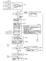
- FIG. 3 is a flowchart showing the procedure / operation of the outdoor security function of the digital security network system according to the above embodiment.
- FIG. 4 is a flowchart showing procedures and operations of the indoor security function of the digital security network system according to the above embodiment.
- FIG. 5 is a flowchart showing the procedure and operation of the fire prevention function of the digital security network system according to the above embodiment.
- FIG. 1 is a block diagram showing a configuration of a digital security network system according to an embodiment of the present invention.
- This digital security network system is connected to the monitoring device 100, which is a digital security network system device main body, and each part inside and outside the building, and is connected to the monitoring device 100 by wire or short-range wireless such as a cable. It is configured to include various input / output devices 110 that detect a state and report an abnormality, and a plurality of communication terminal devices 120 that can communicate via a telephone line 130 that is a public line.
- the user of the communication terminal device 120 can be called a customer as viewed from the digital security network system.
- the monitoring device 100 includes a control unit 101, an input / output unit 102, and an alarm transmission unit 103.
- the control unit 101 is configured by a microcomputer or the like, and controls the entire apparatus and executes a security program to function as a digital security network system.
- the control unit 101 has a memory (not shown) for storing information. Examples of the memory include a semiconductor memory, a magnetic recording device, an optical disk device, and a magneto-optical disk device.
- the control unit 101 tracks the location of the communication terminal device 120, acquires the location information of the communication terminal device 120, the police jurisdiction as a mobile phone reception jurisdiction, and the firefighting jurisdiction A jurisdiction holding unit 101b for holding each zone.
- the police jurisdiction as the mobile phone reception jurisdiction and the fire fighting jurisdiction are not necessarily the same.
- the police jurisdiction in Japan is based on the prefectural unit, and the fire jurisdiction is from the police.
- the jurisdiction is fine. Therefore, in a country where both are equal, there is no need to keep both.
- the control unit 101 refers to the jurisdiction holding unit 101b and identifies the communication terminal device 120 existing in the police jurisdiction or the firefighting jurisdiction according to the content of the emergency. Then, control is performed to notify the specified communication terminal device 120 with priority.
- the control unit 101 determines the voice transmission (warning to the intruder) transmitted from the communication terminal device 120 that has received the report and the repelling device operation command, and if these commands match, the control unit 101 passes through the input / output unit 102. An audio output is output to the speaker 115, and an operation signal is output to the repelling device 118.
- the input / output unit 102 has a function as emergency detection means for detecting an emergency based on the sensor output from the input / output device 110.
- the input / output unit 102 receives position information of each communication terminal device 120 transmitted from the communication terminal device 120 via the telephone line 130, and outputs these signals to the control unit 101.
- the input / output unit 102 receives the voice transmission (warning to the intruder) and the repelling device operation command transmitted from the communication terminal device 120 via the telephone line 130, and outputs these signals to the control unit 101.
- the alarm transmission unit 103 transmits an e-mail, a video including a moving image, or a fire alarm to the communication terminal device 120 and the security company 140 via the telephone line 130.
- the input / output device 110 includes an outdoor / outdoor monitoring unit 110A, a building main room monitoring 110B, and an interphone 110C, each of which includes various sensors and output devices.
- the outdoor area monitoring 110A is mainly for the purpose of security for the entrance / exit, windows, openings, and outer walls, and fire prevention.
- the input device of the building exterior / exterior monitoring unit 110A includes a human sensor 111, an RFID (Radio Frequency Identification) reader 112, and a moving image camera 113.
- the output device includes a light 114 and a speaker 115.
- RFID is an authentication technique using radio waves.
- the RFID reader 112 reads information on the IC chip with an RW (reader / writer) device, and performs object recognition and personal authentication.
- the moving image camera 113 images a moving image.
- the light 114 lights up or blinks to warn a suspicious person or the like.
- the speaker 115 emits a message or a warning sound based on the audio output signal from the input / output unit 102 to warn a suspicious person or the like.
- the main room monitoring 110B in the building is mainly intended for security and fire prevention for hallways, sales floors, cash dispensers (CDs), night depots, rooms and vaults.
- the human sensor 111, the moving image camera 113, the open / close sensor 116, and the fire alarm 117 are input devices for the outdoor monitoring section 110A.
- the output device includes a speaker 115 and a repulse device 118.
- the open / close sensor 116 is a contact sensor or the like that detects opening / closing of a door.
- the repelling device 118 is, for example, a safe room, an enlarged sound device installed in a main room, or a spraying device.
- the repelling device 118 operates based on an operation signal output from the input / output unit 102, and emits a loud sound by an enlarged voice or the like to repel a suspicious person. Also, an alarm device that appeals to the five senses of a person such as a sensor light may be used.
- the intercom 110C is installed at the entrance, and inputs an audio signal such as a visitor's inquiry to the input / output unit 102 of the monitoring apparatus 100.
- the remote control function of the monitoring device 100 can output an audio signal from the communication terminal device 120 to the intercom 110C.
- the communication terminal device 120 is composed of a mobile phone, a PHS (Personal Handy-Phone System), a PDA (Personal Digital Assistants), a smartphone, or the like, and transmits voice and repel device operation commands to the monitoring device 100 via the telephone line 130. To do. In the present embodiment, communication terminal device 120 assumes the use of a mobile phone or a smartphone, and each individual can use it in various places (that is, existing positions). One of the communication terminal devices 120 is arranged together with a PC (Personal Computer) in the security company 140. The communication terminal device 120 can receive a mail or a video including a moving image from the monitoring device 100 via the telephone line 130.
- PC Personal Computer
- the communication terminal device 120 includes a GPS function unit 121 (see FIG. 3) that receives radio waves of position information from a GPS satellite or the like, and obtains current position information from latitude / longitude information based on information received via a GPS antenna.
- the position information is obtained by calculating as a parameter. Generally, altitude information is also obtained by GPS, but it is not used in this embodiment.
- information on the current position of the communication terminal device 120 can be acquired by transmitting / receiving information to / from the mobile phone company server via the base station and the network. The acquired position information is transmitted to the monitoring device 100 in a timely manner.
- Security company 140 investigates abnormal situations when it receives e-mail or video from this digital security network system.
- the security company 140 is not an essential component of the digital security network system according to the present embodiment.
- FIGS. 2 and 3 are flowcharts showing the procedures and operations of the outdoor security function of the digital security network system. This flow is mainly executed by the control unit 101 of the monitoring apparatus 100. Also, it is executed by the control unit (not shown) of the communication terminal device 120 that has received the transmission from the monitoring device 100. In the figure, S indicates each step of the flow executed by the control unit 101 of the monitoring device 100 and the control unit of the communication terminal device 120.
- the control unit 101 performs object recognition based on each sensor input.
- the input / output unit 102 of the monitoring device 100 includes a human sensor 111 installed at an entrance / exit, a window, an opening, an outer wall, or the like as a security (see FIG. 1) function of the outdoor monitoring unit 110A.
- the control unit 101 recognizes that an object (person or the like) has entered the jurisdiction outdoors based on these sensor inputs.
- the control unit 101 performs object determination when the object reaches, for example, 10 m from the entrance, based on the ID information of the RFID reader 112.
- step S12 the control unit 101 determines whether or not the recognized object is a suspicious person based on the RFID determination result. For example, if the RFID ID information is an ID registrant, the control unit 101 determines that the person is a normal person and proceeds to step S13. If the ID information is an ID unregistered person, the object may be a suspicious person. It judges that there exists, and progresses to step S14.
- step S13 the control unit 101 cancels security monitoring based on the RFID determination result, and proceeds to step S22. If the ID is not registered in step S12, the control unit 101 determines the distance between the object and the entrance in step S14.
- step S15 the control unit 101 performs control corresponding to the distance between the object and the entrance. That is, (1) When the distance between the object and the entrance reaches 10 m, the control unit 101 outputs a control signal to the light 114 (see FIG. 1), and turns on the light 114 in step S16. (2) When the distance between the object and the entrance has reached 6 m, the control unit 101 outputs an audio signal to the speaker 115 (see FIG. 1), and in step S16, a dog's cry, a human voice, etc. are output from the speaker 115. Output audio. (3) When the distance between the object and the entrance reaches 5 m, the control unit 101 turns on the indoor TV power supply or turns on the room illumination. With the control correspondence so far, this digital security network system informs the suspicious person that he / she is aware of the intrusion.
- each communication terminal device 120 includes a mobile phone / smartphone or the like that can perform mobile communication, and is used at the location (that is, the location) of each individual. Further, the existence positions of these communication terminal apparatuses 120 are tracked in advance by the monitoring apparatus 100, and the monitoring apparatus 100 can store the existence positions of these communication terminal apparatuses 120.
- the control unit 101 transmits an email to each communication terminal device 120 and the PC of the security company 140.
- the video from the video camera 113 is input to the input / output unit 102 (see FIG. 1) of the monitoring device 100.
- the control unit 101 captures the video from the video camera 113 in step S15.
- the moving image camera 113 may be activated when the distance between the object and the entrance reaches 3 m.
- the control unit 101 transmits the captured image to each communication terminal device 120 and the PC of the security company 140 in step S16.
- the control unit 101 transmits an image in addition to the mail to each communication terminal device 120 and the PC of the security company 140.
- step S15 the process goes through step S15 and proceeds to the final judgment process for the suspicious person. It should be noted that the distance between the object and the entrance can be detected more accurately by detecting a laser or radar signal installed in the building.
- step S ⁇ b> 17 the user of each communication terminal device 120 confirms the video received from the monitoring device 100.
- step S18 if the user of each communication terminal device 120 determines that it is necessary after confirming the video, the user is connected to the monitoring device 100 using the communication terminal device 120, and the interphone is operated by the remote control function of the monitoring device 100. Notifications such as business inquiries are made via 110C.
- step S19 the control unit 101 determines whether or not the person is a suspicious person based on confirmation by the interphone 110C and mail confirmation to be described later.
- the input / output unit 102 emits a threatening voice through the speaker 115 in step S20, and the alarm transmission unit 103 notifies the security company 140 in step S21.
- step S19 the control unit 101 unlocks the entrance door in step S22, cancels the security alarm on the operation panel in step S23, and ends this flow.
- step S24 the process proceeds to step S24 in FIG.
- step S24 the user of each communication terminal device 120 confirms the received video.
- step S ⁇ b> 25 the control unit of the communication terminal device 120 transmits the current position information detected by the GPS function unit 121 to the monitoring device 100.
- step S ⁇ b> 26 in the control unit 101 of the monitoring device 100, the input / output unit 102 receives position information from the communication terminal device 120.
- step S ⁇ b> 27 the control unit 101 determines the location of the prefecture that is the police emergency call telephone reception jurisdiction based on the received location information of the communication terminal device 120.
- step S ⁇ b> 28 the control unit 101 preferentially transmits a notification instruction mail to the police 150 to the communication terminal device 120 that has been determined to exist in the corresponding prefecture where the guarded building exists.
- step S ⁇ b> 29 the control unit of communication terminal device 120 receives the notification instruction mail from monitoring device 100. The user of the communication terminal device 120 visually confirms the real-time video according to the received notification instruction mail, and notifies the police 150 as necessary.
- step S ⁇ b> 30 the control unit of the communication terminal device 120 replies to the monitoring device 100 that the police 150 has been notified or the police 150 has not been notified.
- step S ⁇ b> 31 the control unit 101 of the monitoring device 100 transmits a result mail notified to the police 150 to the other communication terminal devices 120 and the security company 140.
- step S32 the user of the communication terminal device 120 that has reported to the police 150 warns the intruder that the police 150 has been reported, and is intimidated by this warning and moved away. Thereafter, the process proceeds to step S19.
- FIG. 4 is a flowchart showing the procedure / operation of the indoor security function of the digital security network system. This flow is an example applied to a repelling flow against suspicious person intrusion.
- the control unit 101 performs object recognition based on each sensor input.
- the input / output unit 102 of the monitoring device 100 is a person installed in a corridor, sales floor, cas dispenser, night depot, each room, safe room, etc. as a security (see FIG. 1) function of the main room monitoring 110B in the building.
- the inputs of the sensor 111, the RFID reader 112, and the open / close sensor 116 are received.
- the control unit 101 recognizes that an object (such as a person) has entered the room based on these sensor inputs.
- the control unit 101 makes a determination based on the ID information of the RFID reader 112.
- step S42 the control unit 101 determines whether or not the recognized object is a suspicious person based on the RFID determination result. If the ID information of the RFID is an ID registrant, the control unit 101 determines that the person is a normal person and proceeds to step S43. If the ID information is an ID unregistered person, the object may be a suspicious person. Determination is made and the process proceeds to step S44.
- step S43 the control unit 101 cancels security monitoring and proceeds to step S23 (see FIG. 3). If the ID is not registered in step S42, in step S44, the control unit 101 determines that a suspicious person has entered, captures video from the video camera 113, and sends mail / video to the corresponding communication terminal device 120 and the security company 140. Transmit to step S45. Further, the communication terminal device 120 to which the mail / video is transmitted from the monitoring device 100 executes Step S24 of FIG. That is, in step S24 (see FIG. 3), the user of the communication terminal device 120 confirms the received video.
- step S45 the control unit 101 executes a security execution mode.
- the security execution mode is specifically an audio output to the speaker 115 and a power-on of the repelling device.
- step S46 the user of the communication terminal device 120 confirms the received video, and if it is determined that notification is necessary, notifies the police 150 in step S47.
- step S48 the control unit 101 notifies the intruder of the notification to the police 150 and a warning message through the speaker 115, and intimidates and leaves the intruder.
- step S49 the control unit 101 detects that the intruder has reached 2 m, which is the main alert area, using the human sensor 111 or the like.
- step S ⁇ b> 50 the control unit of the communication terminal device 120 transmits the current position information detected by the GPS function unit 121 to the monitoring device 100.
- step S ⁇ b> 51 in the control unit 101 of the monitoring device 100, the input / output unit 102 receives position information from the communication terminal device 120.
- step S ⁇ b> 52 the control unit 101 determines the location of the prefecture that is the police emergency call telephone reception jurisdiction based on the received location information of the communication terminal device 120.
- step S ⁇ b> 53 the control unit 101 preferentially transmits a notification instruction mail to the police 150 to the communication terminal device 120 that is determined to be located in the relevant prefecture where the guarded building is located.
- step S ⁇ b> 54 the control unit of communication terminal device 120 receives the notification instruction mail from monitoring device 100.
- the user of the communication terminal device 120 visually confirms the real-time video according to the received notification instruction mail, and notifies the police 150 as necessary.
- step S55 the control unit 101 again notifies the intruder of the occurrence of an abnormality and a warning message through the speaker 115, and intimidates and leaves the intruder.
- step S56 the control unit 101 times a predetermined time (for example, 30 seconds).
- step S57 the user of the communication terminal device 120 confirms the received moving image.
- step S58 the user of communication terminal apparatus 120 issues a repelling apparatus operation instruction as necessary. Specifically, a repelling device operation instruction is executed by operating a button according to a menu prepared in advance.
- the control unit of the communication terminal device 120 transmits the repelling device operation command (see FIG. 1) to the monitoring device 100 via the telephone line 130.
- the input / output unit 102 of the monitoring device 100 outputs the received repelling device operation command to the control unit 101.
- step S59 the control unit 101 determines that 30 seconds have elapsed since the second warning message notification in step S55 and that a repelling device operation command has been received from the communication terminal device 120.
- the control unit 101 activates the repelling device 118 in step S60.
- the repelling device 118 is, for example, an enlarged sound device or a spray device. By operating the repelling device 118, the intruder is threatened and repelled.
- step S61 the control unit 101 notifies the corresponding communication terminal device 120 and the security company 140 that the repelling device 118 has been activated.
- step S62 the control unit 101 confirms the intruder's leaving by the same method as the intruder's intrusion determination. If the intruder leaves, the control unit 101 sets the alert / guard to the normal mode and ends this flow.
- FIG. 5 is a flowchart showing the procedure and operation of the fire prevention function of the digital security network system.
- step S71 the monitoring device 100 performs fire alarm monitoring. Specifically, the input / output unit 102 of the monitoring device 100 constantly monitors an alarm alarm from the fire alarm 117.
- step S72 the control unit 101 determines whether the alarm alarm from the fire alarm 117 or the thermometer installed in each room has detected an abnormality (for example, 80 ° C.) by the input / output unit 102.
- the control unit 101 When the alarm or temperature abnormality is detected, the control unit 101 outputs an operation instruction for the fire extinguishing device 119 in step S75.
- the fire extinguisher 119 operates according to an operation instruction.
- the control unit 101 shifts to the fire prevention mode and starts moving image.
- the control unit 101 captures the video from the video camera 113, transmits mail / video to the communication terminal device 120 and the security company 140, and proceeds to step S76.
- step S76 the user of the communication terminal device 120 to which the mail / video is transmitted from the monitoring device 100 confirms the received video.
- step S ⁇ b> 77 the control unit of communication terminal device 120 transmits the current position information detected by GPS function unit 121 to monitoring device 100.
- step S ⁇ b> 78 in the control unit 101 of the monitoring device 100, the input / output unit 102 receives position information from the communication terminal device 120.
- step S ⁇ b> 79 the control unit 101 determines where the fire emergency call notification telephone reception jurisdiction is based on the received location information of the communication terminal device 120.
- step S ⁇ b> 80 the control unit 101 transmits a notification instruction mail to the fire department 160 to the communication terminal device 120 that is determined to be in the jurisdiction where the security target building exists.
- step S ⁇ b> 81 the control unit of communication terminal device 120 receives the notification instruction mail from monitoring device 100. The user of the communication terminal device 120 visually confirms the real-time video according to the received notification instruction mail and notifies the fire department 160.
- step S ⁇ b> 82 the control unit 101 notifies the neighborhood of a fire alarm through the speaker 115.
- step S83 the control unit 101 notifies the corresponding communication terminal device 120 and the security company 140 that a notification to the fire department 160, the operation of the fire extinguishing device 119, and a fire alarm to the vicinity have been notified.
- step S84 the control unit 101 confirms the fire extinguishing by the same method as the determination of the alarm alarm or the temperature abnormality.
- the control unit 101 stops the fire extinguishing function and the alarm and ends this flow.
- the monitoring device 100 tracks the location of the communication terminal device 120, acquires the location information of the communication terminal device 120, and the security. Based on the sensor output from the input / output device 110 and the control unit 101 having a police jurisdiction for receiving an emergency call phone and a jurisdiction holding unit 101b for holding a fire jurisdiction where the target building exists An input / output unit 102 for detecting the message and an alarm transmission unit 103 for sending a mail or reporting a video via the telephone line 130. When detecting an emergency, the control unit 101 refers to the jurisdiction holding unit 101b, identifies the communication terminal device 120 existing in the police jurisdiction or the firefighting jurisdiction, and prioritizes the identified communication terminal device 120. Control to report automatically.
- jurisdiction of the police is a prefecture unit, and the jurisdiction of the fire department is finer than the police.
- the police and fire departments have different jurisdictions including wide and narrow.
- jurisdictions can be made different depending on whether a suspicious person enters or approaches or fires.
- position detection may be erroneous near the boundary of the jurisdiction
- the communication terminal device is further prioritized. By making a report, it is possible to make an emergency call more promptly from a mobile phone in the jurisdiction.
- a general-purpose communication terminal device such as a mobile phone is used as a terminal device of the digital security network system via the existing public telephone line 130. This eliminates the need for a terminal device dedicated to the digital security network system, thereby reducing the cost of introducing the digital security network system.
- the digital security network system of the present embodiment since the notification can be confirmed even using a public line, the security of the digital security network system can be improved.
- the present invention is not limited to this.
- a wireless communication line, the Internet, or a LAN is used as the public line. May be.
- a transceiver may be used as a communication terminal device when the public line is wireless communication
- a personal computer or palmtop computer may be used as a communication terminal device when the public line is the Internet or a LAN. Good.
- the name “digital security network system and method” is used. However, this is for convenience of explanation, and may be a security system, a security system, a security method, or the like.
- emergency situations include everything known.
- emergency situations include suspicious person intrusion / approach and fire.
- the approach distance is also reported.
- the report is not limited to e-mail and may be anything.
- the digital security network system and method of the present invention can be realized by a program for causing a computer to function as the digital security network system or method.
- This program may be stored in a computer-readable recording medium.
- the recording medium on which this program is recorded may be the ROM itself of the digital security network system, or a program reading device such as a CD-ROM drive is provided as an external storage device, and the recording medium is inserted therein.
- a CD-ROM or the like that can be read may be used.
- the recording medium may be a magnetic tape, a cassette tape, a flexible disk, a hard disk, an MO / MD / DVD, or a semiconductor memory.
- the digital security network system and method according to the present invention can be used in real time for home security network systems, corporations / commercial facilities, offices, etc., and can prevent the loss of property, life and economy, and has a great effect.
Landscapes
- Engineering & Computer Science (AREA)
- Business, Economics & Management (AREA)
- Emergency Management (AREA)
- Physics & Mathematics (AREA)
- General Physics & Mathematics (AREA)
- Signal Processing (AREA)
- Computer Networks & Wireless Communication (AREA)
- Health & Medical Sciences (AREA)
- Public Health (AREA)
- Computer Security & Cryptography (AREA)
- Environmental & Geological Engineering (AREA)
- Alarm Systems (AREA)
- Telephonic Communication Services (AREA)
- Mobile Radio Communication Systems (AREA)
- Interconnected Communication Systems, Intercoms, And Interphones (AREA)
- Measurement Of The Respiration, Hearing Ability, Form, And Blood Characteristics Of Living Organisms (AREA)
- Emergency Alarm Devices (AREA)
- Gerontology & Geriatric Medicine (AREA)
- General Health & Medical Sciences (AREA)
- Heart & Thoracic Surgery (AREA)
- Cardiology (AREA)
- Physical Education & Sports Medicine (AREA)
- Physiology (AREA)
- Pulmonology (AREA)
- Biophysics (AREA)
- Life Sciences & Earth Sciences (AREA)
- Psychiatry (AREA)
- Psychology (AREA)
- Social Psychology (AREA)
Abstract
Priority Applications (12)
| Application Number | Priority Date | Filing Date | Title |
|---|---|---|---|
| US14/412,930 US9578181B2 (en) | 2012-07-05 | 2012-07-05 | Digital security network system and method |
| PCT/JP2012/067242 WO2014006733A1 (fr) | 2012-07-05 | 2012-07-05 | Système et procédé de réseau de sécurité numérique |
| HK15104640.9A HK1204130B (en) | 2012-07-05 | Digital security network system and method | |
| EP12880437.4A EP2871624B1 (fr) | 2012-07-05 | 2012-07-05 | Système et procédé de réseau de sécurité numérique |
| CN201280074510.2A CN104488007B (zh) | 2012-07-05 | 2012-07-05 | 数字安全网络系统和方法 |
| JP2012538518A JP5120906B1 (ja) | 2012-07-05 | 2012-07-05 | デジタルセキュリティー・ネットワークシステム及び方法 |
| US14/412,952 US9942414B2 (en) | 2012-07-05 | 2012-10-22 | Digital smart security network system, method and program |
| HK15105087.6A HK1204706B (en) | 2012-07-05 | 2012-10-22 | Digital smart security system and method |
| EP12880567.8A EP2871621B1 (fr) | 2012-07-05 | 2012-10-22 | Système et procédé de sécurité intelligents numériques, et programme |
| PCT/JP2012/077265 WO2014006772A1 (fr) | 2012-07-05 | 2012-10-22 | Système et procédé de sécurité intelligents numériques, et programme |
| CN201280074509.XA CN104541312B (zh) | 2012-07-05 | 2012-10-22 | 数字智能安防网络系统和方法 |
| JP2012555630A JP5278981B1 (ja) | 2012-07-05 | 2012-10-22 | デジタルスマート・セキュリティシステム、方法及びプログラム |
Applications Claiming Priority (1)
| Application Number | Priority Date | Filing Date | Title |
|---|---|---|---|
| PCT/JP2012/067242 WO2014006733A1 (fr) | 2012-07-05 | 2012-07-05 | Système et procédé de réseau de sécurité numérique |
Publications (1)
| Publication Number | Publication Date |
|---|---|
| WO2014006733A1 true WO2014006733A1 (fr) | 2014-01-09 |
Family
ID=47692846
Family Applications (2)
| Application Number | Title | Priority Date | Filing Date |
|---|---|---|---|
| PCT/JP2012/067242 Ceased WO2014006733A1 (fr) | 2012-07-05 | 2012-07-05 | Système et procédé de réseau de sécurité numérique |
| PCT/JP2012/077265 Ceased WO2014006772A1 (fr) | 2012-07-05 | 2012-10-22 | Système et procédé de sécurité intelligents numériques, et programme |
Family Applications After (1)
| Application Number | Title | Priority Date | Filing Date |
|---|---|---|---|
| PCT/JP2012/077265 Ceased WO2014006772A1 (fr) | 2012-07-05 | 2012-10-22 | Système et procédé de sécurité intelligents numériques, et programme |
Country Status (5)
| Country | Link |
|---|---|
| US (2) | US9578181B2 (fr) |
| EP (2) | EP2871624B1 (fr) |
| JP (2) | JP5120906B1 (fr) |
| CN (2) | CN104488007B (fr) |
| WO (2) | WO2014006733A1 (fr) |
Cited By (1)
| Publication number | Priority date | Publication date | Assignee | Title |
|---|---|---|---|---|
| CN113393643A (zh) * | 2021-06-10 | 2021-09-14 | 上海安亭地平线智能交通技术有限公司 | 异常行为预警方法、装置、车载终端以及介质 |
Families Citing this family (18)
| Publication number | Priority date | Publication date | Assignee | Title |
|---|---|---|---|---|
| JP6365546B2 (ja) * | 2013-09-13 | 2018-08-01 | コニカミノルタ株式会社 | 被監視者監視装置および該方法ならびに被監視者監視システム |
| US9761120B2 (en) * | 2013-10-28 | 2017-09-12 | Technomirai Co., Ltd. | Digital security system, method and program |
| US20160118036A1 (en) * | 2014-10-23 | 2016-04-28 | Elwha Llc | Systems and methods for positioning a user of a hands-free intercommunication system |
| EP3289506B1 (fr) * | 2015-05-01 | 2021-12-22 | Assa Abloy AB | Utilisation d'un dispositif pouvant être porté pour déterminer une entrée ou une sortie |
| US10271012B2 (en) * | 2016-01-06 | 2019-04-23 | Vivint, Inc. | Home automation system-initiated calls |
| US10382729B2 (en) | 2016-01-06 | 2019-08-13 | Vivint, Inc. | Home automation system-initiated calls |
| JP6877176B2 (ja) * | 2017-02-22 | 2021-05-26 | セコム株式会社 | 監視システム |
| US10308257B2 (en) * | 2017-05-01 | 2019-06-04 | Hitachi, Ltd. | Monitoring respiration of a vehicle operator |
| US11879705B2 (en) * | 2018-07-05 | 2024-01-23 | Mikael Bror Taveniku | System and method for active shooter defense |
| JP2020052946A (ja) * | 2018-09-28 | 2020-04-02 | グローリー株式会社 | 貨幣処理システムおよび貨幣処理装置 |
| JP6529062B1 (ja) * | 2019-02-27 | 2019-06-12 | 株式会社 テクノミライ | デジタルアキュレート・セキュリティシステム、方法及びプログラム |
| US11189141B2 (en) * | 2019-05-24 | 2021-11-30 | Charles Armpriester | Universal threat awareness management system for occupant safety |
| CN110582051B (zh) * | 2019-09-24 | 2021-04-06 | 上海奔果互联网科技有限公司 | 一种基于无线定位技术的客流精准测试方法 |
| US11823559B2 (en) * | 2019-12-16 | 2023-11-21 | Motorola Solutions, Inc. | Method and system to project guidance to building occupants during an emergency situation |
| CN111815257A (zh) * | 2020-05-27 | 2020-10-23 | 福信富通科技股份有限公司 | 一种基于疫情对隔离人员的智能管理方法、装置及系统 |
| CN112328447A (zh) * | 2020-10-30 | 2021-02-05 | 北京三快在线科技有限公司 | 异常事件的上报方法、装置、设备及介质 |
| US10991216B1 (en) * | 2020-12-04 | 2021-04-27 | Khaled Alali | Auditory and visual guidance system for emergency evacuation |
| CN113438306B (zh) * | 2021-06-23 | 2022-07-08 | 杭州萤石软件有限公司 | 一种安防监控系统及安防监控方法、设备 |
Citations (9)
| Publication number | Priority date | Publication date | Assignee | Title |
|---|---|---|---|---|
| JP2001036645A (ja) * | 1999-07-19 | 2001-02-09 | Toyo Commun Equip Co Ltd | 緊急情報伝達システム |
| JP2001118174A (ja) | 1999-10-21 | 2001-04-27 | Maxnet Co Ltd | 異常通報システム |
| JP2002197578A (ja) | 2000-12-25 | 2002-07-12 | Nec Mobiling Ltd | 通信端末装置、データ処理装置及び緊急通報サービスシステム並びに緊急通報サービス方法 |
| JP2002261982A (ja) | 2001-03-05 | 2002-09-13 | Nec Access Technica Ltd | 緊急通報システム |
| JP2003152867A (ja) * | 2001-11-16 | 2003-05-23 | Nec Corp | 移動体通信システムにおける緊急呼通知方式 |
| JP2004265191A (ja) * | 2003-03-03 | 2004-09-24 | Nec Access Technica Ltd | 緊急通報管理装置、移動体無線通信装置およびその緊急通報発信方法、緊急通報システムおよび緊急通報方法 |
| JP2011113255A (ja) | 2009-11-26 | 2011-06-09 | Toyota Home Kk | 地域警備システム |
| JP2011228919A (ja) * | 2010-04-20 | 2011-11-10 | Guard-I Co Ltd | 緊急通報を行う画像通報装置 |
| JP2012113446A (ja) | 2010-11-22 | 2012-06-14 | Sogo Keibi Hosho Co Ltd | 制御装置及び警備システム |
Family Cites Families (50)
| Publication number | Priority date | Publication date | Assignee | Title |
|---|---|---|---|---|
| US5513646A (en) * | 1992-11-09 | 1996-05-07 | I Am Fine, Inc. | Personal security monitoring system and method |
| US5990793A (en) * | 1994-09-02 | 1999-11-23 | Safety Tech Industries, Inc. | Firefighters integrated communication and safety system |
| JPH09305877A (ja) * | 1996-05-15 | 1997-11-28 | Susumu Nakatani | 警報装置の制御方法及び警報装置 |
| EP0825751A3 (fr) * | 1996-08-19 | 2004-07-14 | Casio Computer Co., Ltd. | Commande d'un terminal récepteur de télécommunication par un terminal émetteur avant que le récepteur ne prenne la ligne |
| US6000395A (en) * | 1998-05-07 | 1999-12-14 | Brown; Norma | Avalanche and hyothermia protective system |
| JP2002082887A (ja) * | 2000-09-07 | 2002-03-22 | Sony Corp | メールサーバ、メール処理方法、およびメール処理プログラム格納媒体 |
| US8489063B2 (en) * | 2001-10-24 | 2013-07-16 | Sipco, Llc | Systems and methods for providing emergency messages to a mobile device |
| JP3979351B2 (ja) * | 2003-06-30 | 2007-09-19 | ソニー株式会社 | 通信装置及び通信方法 |
| JP2003153867A (ja) * | 2001-11-21 | 2003-05-27 | Id Technica:Kk | 被検者の健康状態管理装置 |
| US7385496B2 (en) * | 2002-04-15 | 2008-06-10 | Matsushita Electric Industrial Co., Ltd. | Monitoring system |
| US7091852B2 (en) * | 2002-07-02 | 2006-08-15 | Tri-Sentinel, Inc. | Emergency response personnel automated accountability system |
| US7245216B2 (en) * | 2002-07-02 | 2007-07-17 | Tri-Sentinel, Inc. | First responder communications system |
| JP2004054570A (ja) | 2002-07-19 | 2004-02-19 | Noboru Ando | 携帯型緊急通報装置およびこれを用いた緊急通報システム |
| US20040243005A1 (en) * | 2003-05-29 | 2004-12-02 | Rapps Gary M. | Remote speaker microphone having vital sign monitoring capability |
| BRPI0413774A (pt) | 2003-09-15 | 2007-04-10 | David Cohen | detector de situação de emergência, método de detecção de situação de emergência, sistema composto de lógica e sensor corporal, sensor de direção para montagem sobre um corpo móvel e unidade de coordenação central para controlar uma pluralidade de detectores de situação de emergência localizados remotamente |
| US7792273B2 (en) | 2003-09-15 | 2010-09-07 | Accenture Global Services Gmbh | Remote media call center |
| WO2005050849A2 (fr) * | 2003-10-01 | 2005-06-02 | Laird Mark D | Systeme radio d'escorte virtuelle sur campus |
| EP1773185A4 (fr) | 2004-06-18 | 2009-08-19 | Vivometrics Inc | Systemes et procedes de monitorage physiologique en temps reel |
| US10003685B2 (en) * | 2005-07-14 | 2018-06-19 | Binj Laboratories, Inc. | Systems and methods for detecting and controlling transmission devices |
| US8260405B2 (en) * | 2005-12-19 | 2012-09-04 | Koninklijke Philips Electronics N.V. | Monitoring apparatus for monitoring a user's heart rate and/or heart rate variation; wristwatch comprising such a monitoring apparatus |
| US7693984B2 (en) * | 2005-12-29 | 2010-04-06 | Panasonic Electric Works Co., Ltd. | Systems and methods for providing current status data to a requesting device |
| JP3131971U (ja) | 2006-02-20 | 2007-05-31 | 悦正 佐藤 | 携帯電話、及び携帯電話と双方向に通信可能な携帯通信端末の組み合わせ |
| US8442482B2 (en) * | 2006-05-16 | 2013-05-14 | RedSky Technologies, Inc. | Method and system for an emergency location information service (E-LIS) |
| US20070282173A1 (en) * | 2006-05-31 | 2007-12-06 | Bily Wang | Vital sign sending method and a sending apparatus thereof |
| US20090076397A1 (en) * | 2007-09-14 | 2009-03-19 | Corventis, Inc. | Adherent Emergency Patient Monitor |
| US20100166154A1 (en) * | 2007-10-17 | 2010-07-01 | Vixxi Solutions, Inc. | System and method for flexible forwarding of emergency call information |
| US8218871B2 (en) * | 2008-03-05 | 2012-07-10 | International Business Machines Corporation | Detecting behavioral deviations by measuring respiratory patterns in cohort groups |
| US20090322513A1 (en) * | 2008-06-27 | 2009-12-31 | Franklin Dun-Jen Hwang | Medical emergency alert system and method |
| CN101620768A (zh) | 2008-07-04 | 2010-01-06 | 陈茂荣 | 即时报案系统及即时报案方法 |
| CN102150186B (zh) * | 2008-09-10 | 2014-11-12 | 皇家飞利浦电子股份有限公司 | 离床报警系统 |
| AT507941B1 (de) * | 2009-03-02 | 2011-06-15 | Spantec Gmbh | Verfahren zur detektion einer aussergewöhnlichen situation |
| US9002427B2 (en) * | 2009-03-30 | 2015-04-07 | Lifewave Biomedical, Inc. | Apparatus and method for continuous noninvasive measurement of respiratory function and events |
| US20100315228A1 (en) * | 2009-06-16 | 2010-12-16 | Honeywell International Inc. | Wearable data hub for first responders |
| US9031605B2 (en) * | 2010-03-04 | 2015-05-12 | Ipcomm | Mobile femto-cell in a wireless safety network |
| WO2011138794A1 (fr) * | 2010-04-29 | 2011-11-10 | Narasingh Pattnaik | Procédé et système activé par la respiration |
| US8862092B2 (en) * | 2010-06-25 | 2014-10-14 | Emergensee, Inc. | Emergency notification system for mobile devices |
| US9607652B2 (en) * | 2010-08-26 | 2017-03-28 | Blast Motion Inc. | Multi-sensor event detection and tagging system |
| JP2012059002A (ja) | 2010-09-08 | 2012-03-22 | Sogo Keibi Hosho Co Ltd | 通報端末及び画像送信方法 |
| US8988214B2 (en) * | 2010-12-10 | 2015-03-24 | Qualcomm Incorporated | System, method, apparatus, or computer program product for exercise and personal security |
| US8855729B1 (en) * | 2011-01-19 | 2014-10-07 | Ph Technical Labs | Apparatus utilizing projected sound in a mobile companion device |
| CN102184614A (zh) | 2011-05-09 | 2011-09-14 | 张璞 | 数字式遇险求救与辅助自救装置 |
| CN102279997A (zh) | 2011-05-23 | 2011-12-14 | 李怀群 | 一种防盗器 |
| US8793522B2 (en) * | 2011-06-11 | 2014-07-29 | Aliphcom | Power management in a data-capable strapband |
| WO2013071157A1 (fr) * | 2011-11-10 | 2013-05-16 | Sirengps | Système de messagerie d'urgence et procédé permettant de répondre à une urgence |
| GB2504299B (en) * | 2012-07-24 | 2016-09-14 | Med-Bright Medical Solutions Ltd | Device and method for providing information indicative of a stress situation in a human |
| US20140240124A1 (en) * | 2013-02-25 | 2014-08-28 | Exmovere Wireless LLC | Method and apparatus for monitoring, determining and communicating biometric statuses, emotional states and movement |
| US11616837B2 (en) * | 2013-04-11 | 2023-03-28 | Intrepid Networks, Llc | Distributed processing network system, integrated response systems and methods providing situational awareness information for emergency response |
| US9685067B2 (en) * | 2013-10-31 | 2017-06-20 | At&T Intellectual Property I, L.P. | Machine-to-machine (M2M) emergency communications |
| CA2875843A1 (fr) * | 2013-12-20 | 2015-06-20 | Solutions Novika | Procede et systeme de surveillance de l'activite, de la posture et du coeur |
| US9578156B2 (en) * | 2014-09-30 | 2017-02-21 | Samsung Electronics Co., Ltd. | Method and apparatus for operating an electronic device |
-
2012
- 2012-07-05 WO PCT/JP2012/067242 patent/WO2014006733A1/fr not_active Ceased
- 2012-07-05 JP JP2012538518A patent/JP5120906B1/ja not_active Expired - Fee Related
- 2012-07-05 CN CN201280074510.2A patent/CN104488007B/zh not_active Expired - Fee Related
- 2012-07-05 US US14/412,930 patent/US9578181B2/en not_active Expired - Fee Related
- 2012-07-05 EP EP12880437.4A patent/EP2871624B1/fr not_active Not-in-force
- 2012-10-22 CN CN201280074509.XA patent/CN104541312B/zh not_active Expired - Fee Related
- 2012-10-22 WO PCT/JP2012/077265 patent/WO2014006772A1/fr not_active Ceased
- 2012-10-22 JP JP2012555630A patent/JP5278981B1/ja not_active Expired - Fee Related
- 2012-10-22 US US14/412,952 patent/US9942414B2/en not_active Expired - Fee Related
- 2012-10-22 EP EP12880567.8A patent/EP2871621B1/fr not_active Not-in-force
Patent Citations (9)
| Publication number | Priority date | Publication date | Assignee | Title |
|---|---|---|---|---|
| JP2001036645A (ja) * | 1999-07-19 | 2001-02-09 | Toyo Commun Equip Co Ltd | 緊急情報伝達システム |
| JP2001118174A (ja) | 1999-10-21 | 2001-04-27 | Maxnet Co Ltd | 異常通報システム |
| JP2002197578A (ja) | 2000-12-25 | 2002-07-12 | Nec Mobiling Ltd | 通信端末装置、データ処理装置及び緊急通報サービスシステム並びに緊急通報サービス方法 |
| JP2002261982A (ja) | 2001-03-05 | 2002-09-13 | Nec Access Technica Ltd | 緊急通報システム |
| JP2003152867A (ja) * | 2001-11-16 | 2003-05-23 | Nec Corp | 移動体通信システムにおける緊急呼通知方式 |
| JP2004265191A (ja) * | 2003-03-03 | 2004-09-24 | Nec Access Technica Ltd | 緊急通報管理装置、移動体無線通信装置およびその緊急通報発信方法、緊急通報システムおよび緊急通報方法 |
| JP2011113255A (ja) | 2009-11-26 | 2011-06-09 | Toyota Home Kk | 地域警備システム |
| JP2011228919A (ja) * | 2010-04-20 | 2011-11-10 | Guard-I Co Ltd | 緊急通報を行う画像通報装置 |
| JP2012113446A (ja) | 2010-11-22 | 2012-06-14 | Sogo Keibi Hosho Co Ltd | 制御装置及び警備システム |
Non-Patent Citations (1)
| Title |
|---|
| See also references of EP2871624A4 |
Cited By (1)
| Publication number | Priority date | Publication date | Assignee | Title |
|---|---|---|---|---|
| CN113393643A (zh) * | 2021-06-10 | 2021-09-14 | 上海安亭地平线智能交通技术有限公司 | 异常行为预警方法、装置、车载终端以及介质 |
Also Published As
| Publication number | Publication date |
|---|---|
| HK1204706A1 (en) | 2015-11-27 |
| EP2871621A4 (fr) | 2015-08-19 |
| CN104541312B (zh) | 2017-09-01 |
| JP5278981B1 (ja) | 2013-09-04 |
| CN104488007B (zh) | 2017-10-31 |
| CN104541312A (zh) | 2015-04-22 |
| JP5120906B1 (ja) | 2013-01-16 |
| CN104488007A (zh) | 2015-04-01 |
| US9942414B2 (en) | 2018-04-10 |
| EP2871621A1 (fr) | 2015-05-13 |
| EP2871621B1 (fr) | 2018-10-03 |
| WO2014006772A1 (fr) | 2014-01-09 |
| US20150179039A1 (en) | 2015-06-25 |
| US9578181B2 (en) | 2017-02-21 |
| EP2871624A4 (fr) | 2015-07-22 |
| EP2871624B1 (fr) | 2017-03-01 |
| JPWO2014006733A1 (ja) | 2016-06-02 |
| EP2871624A1 (fr) | 2015-05-13 |
| HK1204130A1 (en) | 2015-11-06 |
| US20150229773A1 (en) | 2015-08-13 |
| JPWO2014006772A1 (ja) | 2016-06-02 |
Similar Documents
| Publication | Publication Date | Title |
|---|---|---|
| JP5120906B1 (ja) | デジタルセキュリティー・ネットワークシステム及び方法 | |
| US12361817B2 (en) | Apparatus, system and methods for providing notifications and dynamic security information during an emergency crisis | |
| WO2017072923A1 (fr) | Système, procédé, et programme de prise en charge de sécurité numérique | |
| US9728077B1 (en) | eReceptionist and eNeighborhood watch system for crime prevention and/or verification | |
| KR101841882B1 (ko) | 무인방범 시스템 및 방법 | |
| WO2014072910A1 (fr) | Système d'alarme intelligent avec notification de flux vidéo confirmé par un utilisateur de centre d'appels pour la sécurité publique (psap) combiné à la sécurité des données et à la participation de services publics d'urgence au moyen d'agents de téléphone intelligent | |
| WO2011119273A2 (fr) | Système et appareil permettant de localiser et de surveiller des personnes et/ou des abords | |
| JP6067197B1 (ja) | デジタルスマートセフティシステム、方法及びプログラム | |
| KR20100010548A (ko) | 아동 범죄 예방 시스템 | |
| EP3065115A1 (fr) | Système, procédé et programme de sécurité numérique | |
| KR20200094315A (ko) | 네트워크를 이용한 무인경비시스템 및 무인경비시스템의 설정방법 | |
| KR20090100841A (ko) | 빈 영업점의 자가 무인방범 및 그 제어방법 | |
| KR20120030674A (ko) | 범죄 예방을 위한 이동 단말, 서버, 시스템, 방법, 및 기록 매체 | |
| JP6603546B2 (ja) | 防災支援システム | |
| KR102919384B1 (ko) | Ble장치를 이용한 비상 상황 대응 서비스 제공 방법 및 시스템 | |
| HK1204130B (en) | Digital security network system and method | |
| KR20160085150A (ko) | 방범 저출력심장충격기(aed) 폐쇄회로텔레비젼(cctv) 감시카메라 에스에스(ss)-타워 | |
| JP2011022654A (ja) | 所在情報管理システム | |
| HK1204706B (en) | Digital smart security system and method |
Legal Events
| Date | Code | Title | Description |
|---|---|---|---|
| ENP | Entry into the national phase |
Ref document number: 2012538518 Country of ref document: JP Kind code of ref document: A |
|
| 121 | Ep: the epo has been informed by wipo that ep was designated in this application |
Ref document number: 12880437 Country of ref document: EP Kind code of ref document: A1 |
|
| NENP | Non-entry into the national phase |
Ref country code: DE |
|
| REEP | Request for entry into the european phase |
Ref document number: 2012880437 Country of ref document: EP |
|
| WWE | Wipo information: entry into national phase |
Ref document number: 2012880437 Country of ref document: EP |
|
| WWE | Wipo information: entry into national phase |
Ref document number: 14412930 Country of ref document: US |