WO2014006893A1 - 接近警報装置、接近警報システム、移動体装置と、接近警報システムの故障診断方法 - Google Patents
接近警報装置、接近警報システム、移動体装置と、接近警報システムの故障診断方法 Download PDFInfo
- Publication number
- WO2014006893A1 WO2014006893A1 PCT/JP2013/004128 JP2013004128W WO2014006893A1 WO 2014006893 A1 WO2014006893 A1 WO 2014006893A1 JP 2013004128 W JP2013004128 W JP 2013004128W WO 2014006893 A1 WO2014006893 A1 WO 2014006893A1
- Authority
- WO
- WIPO (PCT)
- Prior art keywords
- unit
- signal
- approach warning
- output
- detection
- Prior art date
- Legal status (The legal status is an assumption and is not a legal conclusion. Google has not performed a legal analysis and makes no representation as to the accuracy of the status listed.)
- Ceased
Links
Images





Classifications
-
- G—PHYSICS
- G08—SIGNALLING
- G08G—TRAFFIC CONTROL SYSTEMS
- G08G1/00—Traffic control systems for road vehicles
- G08G1/16—Anti-collision systems
- G08G1/166—Anti-collision systems for active traffic, e.g. moving vehicles, pedestrians, bikes
-
- B—PERFORMING OPERATIONS; TRANSPORTING
- B60—VEHICLES IN GENERAL
- B60Q—ARRANGEMENT OF SIGNALLING OR LIGHTING DEVICES, THE MOUNTING OR SUPPORTING THEREOF OR CIRCUITS THEREFOR, FOR VEHICLES IN GENERAL
- B60Q5/00—Arrangement or adaptation of acoustic signal devices
- B60Q5/005—Arrangement or adaptation of acoustic signal devices automatically actuated
- B60Q5/008—Arrangement or adaptation of acoustic signal devices automatically actuated for signaling silent vehicles, e.g. for warning that a hybrid or electric vehicle is approaching
-
- G—PHYSICS
- G08—SIGNALLING
- G08G—TRAFFIC CONTROL SYSTEMS
- G08G1/00—Traffic control systems for road vehicles
- G08G1/16—Anti-collision systems
- G08G1/165—Anti-collision systems for passive traffic, e.g. including static obstacles, trees
-
- G—PHYSICS
- G10—MUSICAL INSTRUMENTS; ACOUSTICS
- G10K—SOUND-PRODUCING DEVICES; METHODS OR DEVICES FOR PROTECTING AGAINST, OR FOR DAMPING, NOISE OR OTHER ACOUSTIC WAVES IN GENERAL; ACOUSTICS NOT OTHERWISE PROVIDED FOR
- G10K9/00—Devices in which sound is produced by vibrating a diaphragm or analogous element, e.g. fog horns, vehicle hooters or buzzers
- G10K9/18—Details, e.g. bulbs, pumps, pistons, switches or casings
Definitions
- the present technical field relates to an approach warning device, an approach warning system, a mobile device, and an approach warning that notify a person or an animal of the approach of the mobile device by generating an alarm sound or the like when the mobile device moves.
- the present invention relates to a system failure diagnosis method.
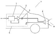
- FIG. 9 is a conceptual diagram of a conventional mobile device 7.
- the approach warning device 6 includes a control unit 1, an amplification unit 2, and a capacitor 3.
- the speaker unit 4 is electrically connected to the output side of the approach warning device 6.
- the approach warning device 6 is mounted on the mobile device 7.
- Control unit 1 receives vehicle signals and outputs audio signals.
- the amplifying unit 2 amplifies the audio signal.
- the output of the amplifying unit 2 is supplied to the speaker unit 4 via the capacitor 3. Note that the capacitor 3 cuts a DC voltage in the output of the amplifying unit 2.
- the approach warning device 6 generates a warning sound 8 from the speaker unit 4.
- Patent Document 1 As prior art document information related to the invention of this application, for example, Patent Document 1 is known.
- the proximity alarm device of the present invention includes a control unit, an amplification unit, an output terminal, a ground terminal, a first detection unit, and a determination unit.
- the control unit receives the reference signal and outputs an audio signal according to the input of the reference signal.
- the amplification unit is electrically connected to the output side of the control unit.
- the output terminal is electrically connected to the output side of the amplifying unit.
- the ground terminal is electrically connected to the ground.
- the first detection unit is electrically connected to the output side of the amplification unit, and outputs a first detection signal based on the output signal of the amplification unit.
- the determination unit is electrically connected to the output side of the first detection unit. Then, the determination unit compares the first detection signal output from the first detection unit with the determination reference signal.
- an abnormality in the speaker connection state can be detected with the speaker connected between the output terminal and the ground terminal.
- an abnormality such as a warning sound not being output from the speaker, thereby preventing a collision between the mobile device and a pedestrian or bicycle.
- the failure diagnosis method for an approach warning system includes a step of outputting an audio signal in response to an input of a reference signal, a step of amplifying the audio signal, and a step of outputting a detection signal based on the amplified audio signal. And a step of comparing the detection signal and the determination reference signal.
- an abnormality in the speaker connection state can be detected with the speaker connected between the output terminal and the ground terminal.
- an abnormality such as a warning sound not being output from the speaker, thereby preventing a collision between the mobile device and a pedestrian or bicycle.
- FIG. 1 is a conceptual diagram of a mobile device according to an embodiment of the present invention.
- FIG. 2 is a block diagram of an approach warning system according to an embodiment of the present invention.
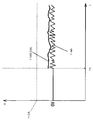
- FIG. 3 is a voltage characteristic diagram showing the operation of the proximity alarm device according to the embodiment of the present invention.
- FIG. 4 is a voltage characteristic diagram of the proximity alarm device according to the embodiment of the present invention.
- FIG. 5 is a voltage characteristic diagram of the proximity alarm device according to the embodiment of the present invention.
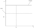
- FIG. 6 is a voltage characteristic diagram of the proximity alarm device according to the embodiment of the present invention.
- FIG. 7 is a control flowchart of the approach warning device according to the embodiment of the present invention.
- FIG. 8 is a block diagram of another example approach warning system according to an embodiment of the present invention.
- FIG. 9 is a block diagram of a conventional approach alarm device.
- the approach warning device 6 when the approach warning device 6 is opened, the audio signal is not transmitted to the speaker unit 4.
- the approach alarm device 6 being open means that the circuit is open. For example, this is a case where a cord connecting the approach warning device 6 and the speaker unit 4 or a line inside the speaker unit 4 is disconnected.
- the proximity alarm device 6 when the proximity alarm device 6 is short-circuited to + B, the other power supply line and the proximity alarm device 6 are connected with low resistance, so an overcurrent flows through the proximity alarm device 6 and the proximity alarm device 6 breaks down. There is. As a result, no audio signal is output from the approach warning device 6.
- the short circuit to + B means a state in which the voltage of another power supply line is applied to the approach alarm device 6. For example, this is a case where a cord connecting between the approach warning device 6 and the speaker unit 4 is short-circuited with a cord connected to a power source such as a battery.
- the approach alarm device 6 cannot detect a failure such as an open circuit or a short circuit with + B. Therefore, the conventional approach alarm device 6 may not notice that no alarm sound is output. That is, there is a possibility that the mobile device 7 travels without the alarm sound being output.
- FIG. 1 is a conceptual diagram of a mobile device 301 equipped with an approach warning device 106 according to an embodiment of the present invention.
- the approach warning device 106 is mounted on the mobile device 301.
- the mobile device 301 includes a main body 302 including a space 307, a drive unit 303, a drive control unit 304, and an approach warning system 201.
- the mobile device 301 may further include a door 305 and a portable device 306. Note that the portable device 306 can give an instruction to lock and unlock the door at a position away from the mobile device 301.
- the driving unit 303, the driving control unit 304, and the approach warning system 201 are mounted on the main body unit 302.
- the mobile device 301 includes a space 307 in the main body 302. For example, a person driving the mobile device 301 gets on the space 307.
- the drive control unit 304 is electrically connected to the drive unit 303 and the approach warning system 201.
- the drive control unit 304 outputs a reference signal to each unit of the mobile device 301 including the drive unit 303 and the approach warning system 201.
- the drive unit 303 is controlled by the reference signal.
- the drive unit 303 includes a motor.
- the drive unit 303 may further include an engine, a tire, and the like. That is, the mobile device 301 is, for example, an electric vehicle or a hybrid car.
- the approach warning system 201 includes an approach warning device 106 and a first warning sound output unit 104.
- the first warning sound output unit 104 is a transducer, and converts a signal output from the approach warning device 106 into a warning sound 202.
- the first warning sound output unit 104 may include a first speaker 104A, a first connection line 104B, and a second connection line 104C.
- the first connection line 104B and the second connection line 104C electrically connect between the approach warning device 106 and the first speaker 104A.
- the first connection line 104B is a signal line
- the second connection line 104C is a ground line.
- the approach alarm device 106 includes a connector connected to the first connection line 104B and the second connection line 104C.
- one end of the first connection line 104 ⁇ / b> B and the second connection line 104 ⁇ / b> C includes a connector connected to the approach alarm device 106.
- the first speaker 104A preferably includes a connector that connects to the first connection line 104B and the second connection line 104C. In this case, a connector connected to the first speaker 104A is included at the other end of the first connection line 104B and the second connection line 104C.
- the approach warning system 201 notifies the person of the approach of the mobile device 301 by outputting a warning sound from the first speaker 104A.
- the approach warning system 201 preferably generates a warning sound 202 when the mobile device 301 travels only with a motor.
- the warning sound 202 output from the approach warning system 201 is, for example, a pseudo engine sound.
- a person can notice that the mobile device 301 is approaching himself / herself without visually recognizing the mobile device 301.
- FIG. 2 is a block diagram of the approach warning system 201 using the approach warning device 106 according to the embodiment of the present invention.
- the approach alarm device 106 includes an input terminal 106A, an output terminal 106B, a ground terminal 106C, a control unit 101, an amplification unit 102, a capacitor 103, a first detection unit 105, and a determination unit 107.
- the control unit 101 receives a reference signal input from the input terminal 106A, and outputs an audio signal S1 according to the received reference signal.
- the amplification unit 102 is electrically connected to the output side of the control unit 101.
- the amplifying unit 102 amplifies the input audio signal S1 and outputs an audio signal S2.
- the output terminal 106B is electrically connected to the output side of the amplifying unit 102.
- the ground terminal 106C is electrically connected to the ground.
- the capacitor 103 is connected in series between the output side of the amplifying unit 102 and the output terminal 106B.
- the capacitor 103 is connected in series with the amplification unit 102.
- the audio signal S2 includes an audio signal S3 that is an AC component and a DC signal component. Since the audio signal S3 is alternating current, it can pass through the capacitor 103.
- the capacitor 103 prevents the DC signal component from being output to the first speaker 104A.
- the first warning sound output unit 104 is electrically connected between the output terminal 106B and the ground terminal 106C. As a result, the first warning sound output unit 104 receives the audio signal S3 output from the approach warning device 106. Then, the first warning sound output unit 104 converts the audio signal S3 into the warning sound 202 and outputs the warning sound 202 to the outside of the mobile device 301.
- the first detection unit 105 is electrically connected to the output side of the amplification unit 102.
- the first detection unit 105 is preferably connected to the output terminal 106B side of the capacitor 103.
- the first detection unit 105 may be connected before the capacitor 103.
- the first detection unit 105 outputs the first detection signal S4 based on the output signal of the amplification unit 102.
- the determination unit 107 is electrically connected to the output side of the first detection unit 105. Then, the determination unit 107 compares the first detection signal S4 with the determination reference signal.
- the access warning device 106 can diagnose a failure of the access warning system 201.
- the signal line is in an open state (disconnected) or short-circuited with another power supply line (+ B) between paths from the amplification unit 102 to the ground.
- it can be diagnosed that the circuit is short-circuited to the ground.
- the driver who drives the mobile device 301 is notified of the diagnosis result diagnosed by the approach warning device 106, the driver can quickly notice the failure of the approach warning system 201. Therefore, the safety of the mobile device 301 equipped with the approach warning system 201 can be improved.
- the control unit 101 stores sound source data that is the source of the audio signal S1.
- the sound source data is a digital signal.
- the sound source data may be created artificially by digital processing of a warning sound 202 that resembles an engine sound, for example.
- the actual engine sound may be collected and the collected engine sound may be converted into a digital signal.
- the control unit 101 converts the sound source data into an analog signal based on the reference signal, and generates an audio signal S1.
- the control unit 101 can output the audio signal S1 to the amplification unit 102.
- the sound source data is preferably compressed and stored by a prescribed method. Thereby, the storage capacity in the control unit 101 can be reduced. In this case, the control unit 101 decompresses the sound source data and then converts it into an analog signal.
- the control unit 101 outputs the audio signal S1 when detecting the reference signal.
- the reference signal is a signal X1 that can detect that movement of the mobile device 301 illustrated in FIG. 1 has started.
- the reference signal a signal indicating the depression angle of the accelerator pedal, a signal indicating that the vehicle is running, a signal indicating the moving speed of the mobile device 301, or the like can be used. Note that only one of these signals may be used as the reference signal. Alternatively, two or more of these signals may be used as the reference signal. In this case, the control unit 101 outputs the audio signal S1 when detecting any of these reference signals.
- the control unit 101 can detect that the movement of the mobile device 301 has started based on the reference signal. And the control part 101 is outputting the audio signal S1, when detecting that the movement of the mobile body apparatus 301 started.
- the approach warning system 201 can start outputting the warning sound 202 almost simultaneously with the start of the mobile device 301 shown in FIG.
- the reference signal used by the control unit 101 to output the audio signal S1 is not limited to the above.
- the signal X2 output by the drive control unit 304 shown in FIG. 1 may be used prior to the driver moving the mobile device 301.
- a signal for unlocking the door 305, an ignition signal (a signal for starting the motor), a signal that the foot brake is released, a signal that the side brake is released, or the shift lever is a drive. It is possible to use a signal indicating this, a signal for controlling the rotation of the motor, or the like.
- the reference signal may be a signal that is not directly generated by the drive control unit 304.
- a signal requesting unlocking of the door 305 can be used from the portable device 306.
- any one of these signals may be used as the reference signal.
- the number of reference signals is not limited to one, and a plurality of signals among the above signals may be used as reference signals.
- the control unit 101 outputs the audio signal S1 when detecting any of these reference signals.
- the control unit 101 may output the audio signal S1 when detecting a plurality of signals among these reference signals.
- FIG. 3 is a voltage characteristic diagram of the approach warning device 106 when the approach warning system 201 is operating normally.
- the horizontal axis represents time
- the vertical axis represents voltage.
- the configuration and operation of the first detection unit 105 and the determination unit 107 when the access warning system 201 shown in FIG. 2 is operating normally will be described.
- power is applied to the amplifier 102 at time T2.
- the amplifying unit 102 By turning on the amplifying unit 102, a direct current due to the offset voltage flows through the output of the amplifying unit 102.
- the first warning sound output unit 104 When the first warning sound output unit 104 is electrically connected to the approach warning device 106 in a correct state, the first warning sound output unit 104 becomes a load. Therefore, when the amplification unit 102 is turned on, the voltage of the line 108 increases instantaneously. As a result, the first detection unit 105 outputs the first detection signal S4 of the voltage waveform 110 to the determination unit 107.
- the determination unit 107 compares the first detection signal S4 with the determination reference signal 113B.
- the determination unit 107 may detect the maximum value of the first detection signal S4 and compare the maximum value with the determination reference signal 113B.
- the determination unit 107 may compare the first detection signal S4 and the determination reference signal 113B every time the first detection signal S4 is acquired.
- the determination reference signal 113B is a threshold for the approach warning device 106 to diagnose a short circuit with the GND. In this case, when all the acquired first detection signals S4 are equal to or lower than the determination reference signal 113B during the predetermined time T3, the maximum voltage of the first detection signal S4 is equal to or lower than the determination reference signal 113B. Can be judged.
- the determination unit 107 compares the detected first detection signal S4 with the determination reference signal 113B until time T3 elapses from time T2.
- the determination unit 107 can diagnose that the approach warning system 201 is operating normally when the maximum voltage of the first detection signal S4 is equal to or less than the determination reference signal 113B.
- the audio signal S1 is preferably output after the time T3 has elapsed from the time T2. That is, if the control unit 101 outputs the audio signal S1 before the time T3, the determination unit 107 may not be able to detect the first detection signal S4 of the voltage waveform 110 by the audio signal S1. Therefore, it is preferable that the control unit 101 does not output a signal during the time T3. Therefore, it is preferable that the control unit 101 outputs the audio signal S1 with a delay of time T3 or more. As a result, the voltage of the line 108 can be set to 0 V during the time T3.
- the drive control unit 304 shown in FIG. 1 outputs a signal X1 after the mobile device 301 starts moving.
- the drive control unit 304 outputs the signal X2 before the mobile device 301 starts moving. Therefore, it is preferable that the control unit 101 outputs the audio signal S1 based on the signal X2 in the reference signal.
- the amplification unit 102 is preferably turned on based on the signal X1 in the reference signal. Since the interval between the signal X1 and the signal X2 is generally longer than the time T3, the control unit 101 outputs the audio signal S1 after the first detection unit 105 completes the detection of the maximum value of the voltage waveform 110. ing.
- the amplifying unit 102 may be turned on based on the signal X2.
- the control unit 101 may output the audio signal S1 based on the signal X1.
- the reference signal that is referred to for turning on the amplification unit 102 is different from the reference signal that the control unit 101 refers to for outputting the audio signal S1.
- the reference signal that is referred to for turning on the amplification unit 102 is output from the drive control unit 304 earlier than the reference signal that the control unit 101 refers to output the audio signal S1 by time T3 or more. Is preferred.
- control unit 101 generates the audio signal S1 from the sound source data after the reference signal is input. With this configuration, it is possible to further delay the output time of the audio signal S1 by the time necessary for generating the audio signal S1 from the sound source data.
- the determination unit 107 can determine the maximum value of the first detection signal S4 of the voltage waveform 110 without being obstructed by the audio signal S1.
- the control unit 101 shown in FIG. 2 outputs an audio signal S1 at time T1. In addition, it is preferable that time T1 has passed time T3 or more from time T2.
- the audio signal S3 having a voltage waveform 112A shown in FIG.
- the first detection unit 105 shown in FIG. 2 detects the audio signal S3. As a result, the first detection unit 105 outputs, for example, the first detection signal S4 having the voltage waveform 112B shown in FIG.
- the first detection unit 105 may include a detector. In this case, the first detection unit 105 detects the audio signal S3 and outputs a first DC detection signal S4.
- the determination reference signal 113A is a threshold value for the approach warning device 106 to diagnose a failure in the open state.
- the determination part 107 is diagnosing that the approach warning system 201 is operate
- FIG. 4 to 6 are voltage characteristic diagrams of the approach alarm device 106 when the approach alarm system 201 is out of order. 4 to 6, the horizontal axis represents time, and the vertical axis represents voltage.
- the approach warning device 106 diagnoses a short-circuit state with the GND will be described with reference to FIG.
- the first connection line 104B is short-circuited to the ground
- the line 108 that supplies the audio signal S3 to the first detection unit 105 is electrically connected to GND. Therefore, as shown in the voltage waveform 114A in FIG. 4, the signal level of the audio signal S3 is suppressed.
- the first detection unit 105 outputs the first detection signal S4 having the voltage waveform 114B to the determination unit 107.
- the determination unit 107 compares the first detection signal S4 with the determination reference signal 113A.
- the determination unit 107 determines that the first detection signal S4 is smaller than the determination reference signal 113A, the determination unit 107 can diagnose that the output side of the amplification unit 102 is short-circuited to the ground.
- the approach alarm device 106 diagnoses a failure in an open state and a state short-circuited to + B.
- the failure in the open state occurs, for example, when the first warning sound output unit 104 is not connected to the approach warning device 106. In this case, the first warning sound output unit 104 does not become a load on the approach warning device 106. Therefore, the maximum value of the voltage of the line 108 is larger than that in the approach warning system 201 is normal.
- the first detection unit 105 outputs the first detection signal S4 having the voltage waveform 111 shown in FIG.
- the determination unit 107 compares the first detection signal S4 with the determination reference signal 113B. Then, when the determination unit 107 determines that the maximum voltage of the first detection signal S4 is larger than the determination reference signal 113B, the determination unit 107 can diagnose that the approach warning system 201 is in an open state and has failed.
- the failure in the state of being short-circuited to + B occurs, for example, when the first connection line 104B is short-circuited with a line connected to the car battery power source.
- the line 108 is connected to the line connected to the battery power source of the car with low resistance. Therefore, an overcurrent flows through the line 108 and the voltage of the line 108 is high. Therefore, as shown in FIG. 6, the value of the first detection signal S4 becomes the upper limit voltage value 116 almost at the same time when the amplifier 102 is turned on. In this case, the first detection signal S4 is maintained at the upper limit voltage value 116 after that.
- the determination unit 107 determines that the maximum voltage of the first detection signal S4 has reached the upper limit voltage value 116, the determination unit 107 diagnoses that the approach alarm system 201 has failed in a state of being short-circuited to + B. it can.
- the determination unit 107 observes the first detection signal S4 for a specified time. In this case, when the determination unit 107 detects that the voltage of the line 108 becomes approximately 0 V within a specified time, it can diagnose that the failure is in the open state. On the other hand, when the determination unit 107 detects that the first detection signal S4 maintains the upper limit voltage value 116 for a predetermined time, the determination unit 107 can diagnose that the failure is a short circuit to + B.
- the approach alarm device 106 can diagnose failures in the open state, the GND short-circuit state, and the + B short-circuit state. Therefore, various failures in which the warning sound 202 is not output from the first warning sound output unit 104 due to the failure of the approach warning system 201 can be detected. As a result, the quality and reliability of the approach warning system 201 are increased. Further, a collision accident between the mobile device 301 and a person can be prevented in advance. Furthermore, since the approach warning device 106 can be configured with a simple circuit, the price can be reduced.
- control unit 101 may output a signal indicating whether or not the audio signal S1 is output. Then, it is preferable that the determination unit 107 accepts a signal indicating whether or not the audio signal S1 is output. In this case, the determination unit 107 preferably compares the first detection signal S4 of the voltage waveform 110 with the determination reference signal 113B when detecting a signal indicating that there is no output of the audio signal S1. When the determination unit 107 detects a signal indicating that the audio signal S1 is being output, the determination unit 107 compares the determination reference signal 113A with the first detection signal S4 of the voltage waveform 112B or the voltage waveform 114A. It is preferable to do.
- FIG. 7 is a control flowchart of the approach warning device 106.
- the failure diagnosis method for the approach warning device 106 includes a step 151 for outputting the audio signal S1 in response to the input of the reference signal, a step 152 for amplifying the audio signal S1, and a first based on the amplified audio signal S3.
- a step 153 for outputting the detection signal S4 and a step 154 for comparing the first detection signal S4 and the determination reference signal 113A or the first detection signal S4 and the determination reference signal 113B are provided.
- step 151 the processing of the control unit 101 is performed.
- step 152 the processing of the amplifying unit 102 is performed.
- step 153 the processing of the first detection unit 105 is performed.
- step 154 processing of the determination unit 107 is performed.
- the control unit 101 and the determination unit 107 are preferably configured in the signal processing device 109. In this case, step 151 and step 154 can be executed by software.
- FIG. 8 is a block diagram of another example approach warning system 601 according to an embodiment of the present invention.
- the approach warning system 601 includes an approach warning device 506 instead of the approach warning device 106 of the approach warning system 201 shown in FIG. Further, the approach warning system 601 preferably includes a notification unit 603 and an input device 604.
- the approach warning device 506 includes an input terminal 106A, an output terminal 106B, a ground terminal 106C, an input unit 506D, a notification terminal 506E, a signal generation unit 501, an amplification unit 502, a capacitor 103, a first detection unit 105, a second detection unit 505, An AD converter 509A, an AD converter 509B, an AD converter 509C, and a determination unit 507 are included.
- the amplifying unit 502 includes a monitor terminal 502A, a gain control terminal 502B, and a power supply terminal 502C.
- the monitor terminal 502A outputs a voltage value S6 proportional to the current flowing through the amplifying unit 502.
- the amplification unit 502 changes its amplification gain according to the control signal S7 input to the gain control terminal 502B.
- the determination unit 507 includes a determination unit 107, a second determination unit 507B, and a third determination unit 507C. Note that the approach warning device 506 may further include a setting unit.
- the signal generation unit 501 includes a detector 501A, a power supply control unit 501B, and a control unit 101.
- the reference signal supplied to the input terminal 106A is input to the detector 501A.
- the output side of the detector 501A is electrically connected to the control unit 101 and the power supply control unit 501B.
- the detector 501A When detecting that the reference signal is input, the detector 501A outputs a signal indicating that the reference signal has been detected to the control unit 101 and the power supply control unit 501B.
- the output side of the power supply control unit 501B is electrically connected to the amplification unit 502.
- the output signal of the amplification unit 502 is supplied to the output terminal 106 ⁇ / b> B and the first detection unit 105 through the capacitor 103. It is more preferable to connect the output side of the power supply control unit 501B to the input side of the control unit 101.
- the output side of the first detection unit 105 is electrically connected to the determination unit 107 and the second determination unit 507B via the AD converter 509A.
- the amplification unit 502 side of the capacitor 103 is electrically connected to the second detection unit 505.
- the output side of the 2nd detection part 505 is electrically connected to the 2nd determination device 507B via AD converter 509B.
- the second detection unit 505 can detect the magnitude of the audio signal S2. That is, the second detection unit 505 can detect the voltage before the capacitor 103.
- the second detection unit 505 outputs a second detection signal S5 corresponding to the level of the audio signal S2.
- the second determiner 507B compares the first detection signal S4 with the second detection signal S5. With the above configuration, the second determiner 507B can diagnose that the capacitor 103 is short-circuited when determining that the magnitude of the first detection signal S4 and the magnitude of the second detection signal S5 are equal.
- the monitor terminal 502A is electrically connected to the input side of the third determiner 507C via the AD converter 509C.
- the third determiner 507C compares the voltage value S6 output from the monitor terminal 502A with a predetermined threshold value. If the third determiner 507C determines that the voltage value output from the monitor terminal 502A is larger than the threshold value, the third determiner 507C diagnoses that an overcurrent flows through the amplifier 502.
- the output side of the determination unit 107, the second determination unit 507B, and the third determination unit 507C is electrically connected to the power supply control unit 501B and the notification terminal 506E.
- a notification unit 603 is electrically connected to the notification terminal 506E.
- the determination unit 107, the second determination unit 507B, and the third determination unit 507C output the determination results in the power supply control unit 501B and the notification unit 603, respectively.
- the determination unit 107 outputs a signal S8 indicating that the approach alarm system 601 is out of order. Yes.
- the signal S8 preferably includes a signal S81 output from the determination unit 107, S82 output from the second determiner 507B, and S83 output from the third determiner 507C.
- the signal S81 can determine which of the failure is an open state, a ground short circuit, or a + B short circuit.
- the power supply control unit 501B preferably stops the supply of power to the amplifying unit 502 when receiving the signal S8 indicating that a failure has occurred. Furthermore, when the power supply control unit 501B is connected to the control unit 101, it is more preferable that the approach warning device 506 stops the output of the audio signal S1 of the control unit 101. Therefore, the approach warning device 506 may stop the supply of power supplied to the control unit 101.
- the overcurrent from continuing to flow through the amplifying unit 502 when the approach alarm system 601 has failed due to the overcurrent flowing through the amplifying unit 502.
- the proximity warning system 601 is broken due to the short circuit of the capacitor 103, the direct current component included in the audio signal S2 can be prevented from being supplied to the first speaker 104A. Therefore, failure of the first speaker 104A can be prevented.
- the notification unit 603 when the notification unit 603 receives the signal S8 indicating that there is a failure, the notification unit 603 notifies the driver or the like of the diagnosis result of the determination unit 507. Note that the notification unit 603 can determine where a failure has occurred based on the signal S81, the signal S82, and the signal S83, and thus can make notification according to the content of the failure.
- the second speaker 603A may be used as the notification unit 603, the second speaker 603A. That is, the approach warning system 601 may further include a second speaker 603A in addition to the first speaker 104A. In this case, the second speaker 603A is installed in the main body 302 so that a notification sound can be output to the space 307 shown in FIG.
- the second speaker 603A can notify the driver or the like of the failure by sound. Therefore, the driver's visual recognition becomes unnecessary. As a result, the failure can be recognized regardless of the driver's visual field.
- the notification unit 603 may be an indicator 603B that displays a failure by emitting light or the like. With this configuration, even when the driver listens to music or the like, the driver can recognize the failure of the approach warning system 601. Further, the notification unit 603 may include both the second speaker 603A and the indicator 603B. With this configuration, the driver can more easily recognize the failure of the approach warning system 601.
- 1st speaker 104A is arrange
- the place where the first speaker 104A can be arranged may be different.
- first speaker 104 ⁇ / b> A is disposed far from the front end of mobile device 301, the volume of warning sound 202 that a person hears is low.
- the approach warning device 506 is provided with a setting unit 510.
- the input device 604 is electrically connected to the input unit 506D.
- the input unit 506D is electrically connected to the input side of the setting unit 510.
- the output side of setting unit 510 is electrically connected to the input side of gain control terminal 502B, determination unit 107, and third determination unit 507C.
- the setting unit 510 can control the amplification degree of the amplification unit 502 in accordance with the set value input to the input device 604.
- the setting unit 510 can output the determination reference signal 113A and the determination reference signal 113B corresponding to the amplification degree of the amplification unit 502 to the determination unit 107.
- the setting unit 510 can output the threshold value of the third determination unit 507C corresponding to the amplification degree of the amplification unit 502 to the third determination unit 507C. Therefore, for example, even if the vehicle type is different and the position where the first speaker 104A is arranged is different, the warning sound 202 output to the outside of the vehicle can be set to a predetermined level.
- the AD converter 509A, AD converter 509B, and AD converter 509C sample 100 data in 10 msec from the first detection signal S4. Furthermore, it is preferable that the determination unit 107, the second determiner 507B, and the third determiner 507C calculate an average value of 100 sampled data. This configuration makes it less susceptible to instantaneous noise and the like. Therefore, the quality and reliability of the proximity warning device can be further increased.
- the failure diagnosis method of the approach warning device 506 includes step 151, step 152, step 153, and step 154 shown in FIG.
- step 151 in addition to the control unit 101, processing of the detector 501A and the power supply control unit 501B is performed. In step 151, it is preferable to further perform processing of setting unit 510 and input unit 506D. In step 151, the input unit 604 may be processed.
- step 152 the processing of the amplifying unit 502 is performed.
- step 153 in addition to the process of the 1st detection part 105, the process of the 2nd detection part 505 is performed.
- step 154 in addition to the processing of the determination unit 107, processing of the second determiner 507B, the third determiner 507C, the AD converter 509A, the AD converter 509B, and the AD converter 509C is performed.
- step 154 the processing of the notification unit 603 may be performed.
- the signal generation unit 501, the determination unit 507, and the setting unit 510 are preferably configured in the signal processing device 511.
- the signal generation unit 501, the determination unit 507, and the setting unit 510 can be configured by software.
- the failure diagnosis method of the approach warning device 506 may also perform the processing of the setting unit 510 in step 151.
- the approach warning device according to the present invention is useful for an electric vehicle, a hybrid car, and the like that are driven by a motor.
Landscapes
- Physics & Mathematics (AREA)
- Engineering & Computer Science (AREA)
- Acoustics & Sound (AREA)
- General Physics & Mathematics (AREA)
- Multimedia (AREA)
- Mechanical Engineering (AREA)
- Emergency Alarm Devices (AREA)
- Electric Propulsion And Braking For Vehicles (AREA)
- Traffic Control Systems (AREA)
Abstract
Description
2 増幅部
3 コンデンサ
4 スピーカ部
6 接近警報装置
7 移動体装置
8 警告音
101 制御部
102 増幅部
103 コンデンサ
104 第1警告音出力部
104A 第1スピーカ
104B 第1接続線
104C 第2接続線
105 第1検出部
106 接近警報装置
106A 入力端子
106B 出力端子
106C グランド端子
106D 入力部
107 判定部
108 ライン
109 信号処理装置
110 電圧波形
111 電圧波形
112A 電圧波形
112B 電圧波形
113A 判定基準信号
113B 判定基準信号
114A 電圧波形
114B 電圧波形
116 上限電圧値
151 ステップ
152 ステップ
153 ステップ
154 ステップ
201 接近警報システム
202 警告音
301 移動体装置
302 本体部
303 駆動部
304 駆動制御部
305 ドア
306 携帯機
307 空間
501 信号生成部
501A 検知器
501B 電源制御部
502 増幅部
502A モニタ端子
502B 利得制御端子
502C 電源端子
505 第2検出部
506 接近警報装置
506D 入力部
506E 報知端子
507 判定部
507B 第2判定器
507C 第3判定器
509A ADコンバータ
509B ADコンバータ
509C ADコンバータ
510 設定部
511 信号処理装置
601 接近警報システム
603 通知部
604 入力器
Claims (29)
- 参照信号を受け付け、前記参照信号の入力に応じて、オーディオ信号を出力する制御部と、
前記制御部の出力側に電気的に接続された増幅部と、
前記増幅部の出力側に電気的に接続された出力端子と、
グランドと電気的に接続されたグランド端子と、
前記増幅部の出力側に電気的に接続され、前記増幅部の出力信号に基づき第1検出信号を出力する第1検出部と、
前記第1検出部の出力側に電気的に接続され、前記第1検出部から出力された前記第1検出信号と、判定基準信号とを比較する判定部と、を備えた、
接近警報装置。 - 前記増幅部と前記出力端子との間に直列接続されたコンデンサをさらに備えた、
請求項1記載の接近警報装置。 - 前記コンデンサの前記増幅部側に接続され、前記増幅部の出力信号に基づき第2検出信号を出力する第2検出部を、さらに備え、
前記第2検出部の出力側は、前記判定部へ電気的に接続され、
前記第1検出部は、前記コンデンサの前記出力端子側に接続され、
前記判定部は、前記第2検出部から出力された前記第2検出信号と、第2判定基準信号とを比較する
請求項2記載の接近警報装置。 - 前記第1検出部は、検波器を含む、
請求項1記載の接近警報装置。 - 前記増幅部の増幅度の設定を受け付ける入力部と、
前記判定部と前記増幅部とに電気的に接続されて、前記入力部で受け付けた設定に基づき前記増幅部の増幅度を設定し、かつ前記判定基準信号の値を前記増幅度に応じた値へと変更する設定部と、をさらに備えた、
請求項1に記載の接近警報装置。 - 前記第1検出部と前記判定部の間には、ADコンバータをさらに備えた、
請求項1記載の接近警報装置。 - 前記ADコンバータは、前記検出部で検出された信号から、10msecの間に100個のデータをサンプリングし、前記判定器は、前記サンプリングされた100個のデータの平均値を算出する、
請求項6記載の接近警報装置。 - 前記増幅部は、前記増幅部に流れる電流に比例した電圧値を出力するモニタ端子を有し、前記モニタ端子は、前記判定部の入力側へ接続され、
前記判定部は、前記電圧値とあらかじめ定められた閾値とを比較する、
請求項1記載の接近警報装置。 - 前記電圧値が前記閾値よりも大きい場合、前記判定部は、前記増幅部に過電流が流れていると判定する、
請求項8記載の接近警報装置。 - 前記制御部の入力側に接続された検知器と、
前記検知器の出力側および前記増幅部と接続された電源制御部
と、を有する、
請求項1記載の接近警報装置。 - 前記制御部は、前記検知器の出力に基づいて、前記オーディオ信号を遅延して前記増幅部に出力する請求項10記載の接近警報装置。
- 請求項1に記載の接近警報装置と、
前記接近警報装置の前記出力端子と前記グランド端子との間に電気的に接続された第1スピーカと、を備え、
前記判定器は、前記検出信号と前記判定基準信号との比較結果に基づいて、前記出力端子と前記第1スピーカと前記グランド端子との間の電気的な異常を検知する、
接近警報システム。 - 前記接近警報装置に設けられた前記判定器に電気的に接続され、前記判定器の判定結果を通知する通知部をさらに備えた、
請求項12記載の接近警報システム。 - 前記通知部は、第2スピーカである、
請求項13記載の接近警報システム。 - 前記通知部は、インジケータである、
請求項13記載の接近警報システム。 - 本体部と、
前記本体部に搭載された駆動部と、
請求項1に記載の接近警報装置と、
前記接近警報装置の前記出力端子と前記グランド端子との間に接続され、前記本体部の外へ放音可能に設置された第1スピーカと、を備え、
前記判定器は、前記検出信号と前記判定基準信号との比較結果に基づいて、前記出力端子と前記第1スピーカと前記グランド端子との間の電気的な異常を検知する、
移動体装置。 - 参照信号の入力に応じてオーディオ信号を出力するステップと、
前記オーディオ信号を増幅するステップと、
前記増幅されたオーディオ信号に基づき検出信号を出力するステップと、
前記検出信号と、判定基準信号とを比較するステップと、を備えた、
接近警報システムの故障診断方法。 - 前記検出信号を出力する際には、前記オーディオ信号を検波し、前記オーディオ信号に基づいた直流信号を前記検出信号として出力する、
請求項17に記載の接近警報システムの故障診断方法。 - 前記増幅部の増幅度を設定するとともに、前記判定基準信号の値を前記増幅部の増幅度に応じた値へと変更するステップをさらに備えた、
請求項17に記載の接近警報システムの故障診断方法。 - 前記検出信号をデジタル信号へと変換するステップをさらに備えた、
請求項17記載の接近警報システムの故障診断方法。 - 前記検出信号を前記デジタル信号へと変換する際には、前記検出信号から、10msecの間に100個のデータをサンプリングし、前記サンプリングされたデータの平均値を算出する、
請求項20記載の接近警報システムの故障診断方法。 - 前記オーディオ信号を増幅する際に、前記オーディオ信号を増幅するときの電圧値を検知し、前記電圧値とあらかじめ定められた閾値とを比較する、
請求項17記載の接近警報システムの故障診断方法。 - 前記電圧値が、前記閾値よりも大きい場合に、前記オーディオ信号を増幅する際に過電流が流れていると判定する、
請求項22記載の接近警報システムの故障診断方法。 - 前記増幅されたオーディオ信号を警報音へ変換して出力するステップをさらに備えた、
請求項17記載の接近警報システムの故障診断方法。 - 前記検出信号と前記判定基準信号との比較結果を通知するステップをさらに備えた、
請求項17記載の接近警報システムの故障診断方法。 - 音によって前記比較結果を通知する、
請求項25記載の接近警報システムの故障診断方法。 - 表示によって前記比較結果を通知する、
請求項25記載の接近警報システムの故障診断方法。 - 前記参照信号を検知するステップと、
前記参照信号の検知結果に基づいて、前記増幅部を動作させるステップと、をさらに備えた、
請求項17記載の接近警報システムの故障診断方法。 - 前記参照信号の入力から遅延して前記オーディオ信号を出力する請求項17記載の接近警報システムの故障診断方法。
Priority Applications (4)
| Application Number | Priority Date | Filing Date | Title |
|---|---|---|---|
| CN201380035371.7A CN104428169B (zh) | 2012-07-04 | 2013-07-03 | 接近报警装置、接近报警系统、移动体装置、接近报警系统的故障诊断方法 |
| EP13812650.3A EP2871095B1 (en) | 2012-07-04 | 2013-07-03 | Proximity alarm device, proximity alarm system, mobile device, and method for diagnosing failure of proximity alarm system |
| JP2014523603A JP6314320B2 (ja) | 2012-07-04 | 2013-07-03 | 接近警報装置、接近警報システム、移動体装置と、接近警報システムの故障診断方法 |
| US14/404,910 US9779625B2 (en) | 2012-07-04 | 2013-07-03 | Proximity alarm device, proximity alarm system, mobile device, and method for diagnosing failure of proximity alarm system |
Applications Claiming Priority (2)
| Application Number | Priority Date | Filing Date | Title |
|---|---|---|---|
| JP2012150097 | 2012-07-04 | ||
| JP2012-150097 | 2012-07-04 |
Publications (1)
| Publication Number | Publication Date |
|---|---|
| WO2014006893A1 true WO2014006893A1 (ja) | 2014-01-09 |
Family
ID=49881666
Family Applications (1)
| Application Number | Title | Priority Date | Filing Date |
|---|---|---|---|
| PCT/JP2013/004128 Ceased WO2014006893A1 (ja) | 2012-07-04 | 2013-07-03 | 接近警報装置、接近警報システム、移動体装置と、接近警報システムの故障診断方法 |
Country Status (5)
| Country | Link |
|---|---|
| US (1) | US9779625B2 (ja) |
| EP (1) | EP2871095B1 (ja) |
| JP (1) | JP6314320B2 (ja) |
| CN (1) | CN104428169B (ja) |
| WO (1) | WO2014006893A1 (ja) |
Cited By (4)
| Publication number | Priority date | Publication date | Assignee | Title |
|---|---|---|---|---|
| CN106663420A (zh) * | 2014-04-29 | 2017-05-10 | Ls汽车电子株式会社 | 环境友好车辆的操作声音产生装置及其控制方法 |
| EP3179463A4 (en) * | 2014-08-07 | 2018-04-04 | Hitachi Automotive Systems, Ltd. | Action planning device |
| JP2018067075A (ja) * | 2016-10-18 | 2018-04-26 | 株式会社京三製作所 | 視覚障害者用音響付加装置 |
| WO2025023068A1 (ja) * | 2023-07-24 | 2025-01-30 | パナソニックIpマネジメント株式会社 | 情報処理方法、情報処理装置、および、プログラム |
Families Citing this family (5)
| Publication number | Priority date | Publication date | Assignee | Title |
|---|---|---|---|---|
| JP6793300B2 (ja) * | 2016-02-10 | 2020-12-02 | パナソニックIpマネジメント株式会社 | 車両近接報知装置 |
| US9975481B2 (en) * | 2016-05-23 | 2018-05-22 | Ford Global Technologies, Llc | Method and apparatus for animal presence alert through wireless signal detection |
| JP7013093B2 (ja) | 2018-05-01 | 2022-01-31 | アルパイン株式会社 | 故障検出装置、移動体搭載装置、故障検出方法 |
| DE102023101564B3 (de) | 2023-01-23 | 2024-05-16 | Cariad Se | Spannungsbasierte diagnose eines lautsprechers in einem audioausgabesystem |
| DE102023101565B3 (de) | 2023-01-23 | 2024-05-08 | Cariad Se | Strombasierte diagnose eines lautsprechers in einem audioausgabesystem |
Citations (6)
| Publication number | Priority date | Publication date | Assignee | Title |
|---|---|---|---|---|
| JP2000175299A (ja) * | 1998-12-07 | 2000-06-23 | Toa Corp | スピーカラインの検査装置 |
| JP2003070098A (ja) * | 2001-08-23 | 2003-03-07 | Fujitsu Access Ltd | 複数のスピーカを有する放音設備のスピーカ点検方式 |
| WO2009087772A1 (ja) * | 2008-01-10 | 2009-07-16 | Toa Corporation | スピーカラインの検査装置 |
| JP2011031865A (ja) | 2009-07-31 | 2011-02-17 | Atsuo Watabe | 自動車 |
| JP2011091642A (ja) * | 2009-10-22 | 2011-05-06 | Oki Semiconductor Co Ltd | 過電流検出回路及び信号増幅装置 |
| JP2012056400A (ja) * | 2010-09-07 | 2012-03-22 | Toyota Motor Corp | 接近通報音出力装置 |
Family Cites Families (28)
| Publication number | Priority date | Publication date | Assignee | Title |
|---|---|---|---|---|
| US4881058A (en) * | 1988-10-25 | 1989-11-14 | Audiosone, Inc. | Combined audible and visual alarm system |
| US5345510A (en) * | 1992-07-13 | 1994-09-06 | Rauland-Borg Corporation | Integrated speaker supervision and alarm system |
| JP3244797B2 (ja) * | 1992-09-08 | 2002-01-07 | 富士通株式会社 | 自己故障検知機能付自動車衝突防止レーダ |
| SE510417C2 (sv) * | 1996-03-06 | 1999-05-25 | Nokia Satellite Systems Ab | Överströmsskydd i en satellitmottagare |
| AU718281B2 (en) * | 1998-03-25 | 2000-04-13 | Robert Bosch Gmbh | A drive circuit for a sounder |
| FR2783630B1 (fr) * | 1998-09-23 | 2000-12-15 | Pierre Guilmette | Systeme de synthese sonore permettant d'obtenir en sortie une suite d'echantillons electriques |
| US6859539B1 (en) | 2000-07-07 | 2005-02-22 | Yamaha Hatsudoki Kabushiki Kaisha | Vehicle sound synthesizer |
| JP3661573B2 (ja) * | 2000-07-24 | 2005-06-15 | 株式会社村田製作所 | 電圧制御発振器、電圧制御発振器装置およびレーダ装置 |
| GB0220907D0 (en) * | 2002-09-10 | 2002-10-16 | Ingenia Holdings Ltd | Security device and system |
| JP2004136831A (ja) | 2002-10-21 | 2004-05-13 | Takumakkusu:Kk | 音響発生装置および自動車 |
| US7188037B2 (en) | 2004-08-20 | 2007-03-06 | Microcraft | Method and apparatus for testing circuit boards |
| EP1957992B1 (en) | 2005-12-06 | 2011-05-25 | Harman International Industries, Incorporated | Diagnostic system for power converter |
| JP2008085476A (ja) * | 2006-09-26 | 2008-04-10 | Patoraito:Kk | 警報音発生装置 |
| US20080215240A1 (en) * | 2006-12-18 | 2008-09-04 | Damian Howard | Integrating User Interfaces |
| TW200835375A (en) | 2007-02-01 | 2008-08-16 | Oxiwin Technology Inc | Loudspeaker device |
| JP2008244554A (ja) * | 2007-03-26 | 2008-10-09 | Toa Corp | オーディオ装置の過電流保護回路 |
| TWI350708B (en) * | 2007-06-26 | 2011-10-11 | Wolo Mfg Corp | Computer controlled amplifier and speaker system with power conservation feature |
| US8204243B2 (en) | 2007-09-21 | 2012-06-19 | United Parcel Service Of America, Inc. | Synthetic engine sound for electric vehicle based on detected direction of travel |
| CN101264755B (zh) | 2008-03-06 | 2010-07-28 | 上海交通大学 | 车辆行驶安全智能监控装置 |
| US20100095030A1 (en) * | 2008-10-15 | 2010-04-15 | Aten International Co., Ltd. | Control management system |
| CN101380927B (zh) | 2008-10-17 | 2012-10-03 | 奇瑞汽车股份有限公司 | 一种汽车行人防撞红外线自动感应装置 |
| JP2010228564A (ja) * | 2009-03-26 | 2010-10-14 | Yamaha Corp | 自動車 |
| MX2011012736A (es) * | 2009-05-29 | 2011-12-16 | Sharp Kk | Aparato de reproduccion de sonido, metodo de reproduccion de sonido y medio de grabacion. |
| JP5206762B2 (ja) | 2010-10-19 | 2013-06-12 | 株式会社デンソー | 車両用警報装置 |
| JP5298169B2 (ja) | 2011-07-27 | 2013-09-25 | アンデン株式会社 | 車両接近通報装置 |
| JP5423748B2 (ja) * | 2011-09-17 | 2014-02-19 | 株式会社デンソー | 車両運行通知音発生用スピーカ回路の異常検出装置 |
| JP5538662B2 (ja) | 2012-02-07 | 2014-07-02 | 三菱電機株式会社 | 車両接近通報装置、およびその故障診断方法 |
| US20130314836A1 (en) * | 2012-05-24 | 2013-11-28 | Allegro Microsystems, Inc. | Transistor Overcurrent Detection |
-
2013
- 2013-07-03 WO PCT/JP2013/004128 patent/WO2014006893A1/ja not_active Ceased
- 2013-07-03 JP JP2014523603A patent/JP6314320B2/ja not_active Expired - Fee Related
- 2013-07-03 US US14/404,910 patent/US9779625B2/en active Active
- 2013-07-03 CN CN201380035371.7A patent/CN104428169B/zh not_active Expired - Fee Related
- 2013-07-03 EP EP13812650.3A patent/EP2871095B1/en active Active
Patent Citations (6)
| Publication number | Priority date | Publication date | Assignee | Title |
|---|---|---|---|---|
| JP2000175299A (ja) * | 1998-12-07 | 2000-06-23 | Toa Corp | スピーカラインの検査装置 |
| JP2003070098A (ja) * | 2001-08-23 | 2003-03-07 | Fujitsu Access Ltd | 複数のスピーカを有する放音設備のスピーカ点検方式 |
| WO2009087772A1 (ja) * | 2008-01-10 | 2009-07-16 | Toa Corporation | スピーカラインの検査装置 |
| JP2011031865A (ja) | 2009-07-31 | 2011-02-17 | Atsuo Watabe | 自動車 |
| JP2011091642A (ja) * | 2009-10-22 | 2011-05-06 | Oki Semiconductor Co Ltd | 過電流検出回路及び信号増幅装置 |
| JP2012056400A (ja) * | 2010-09-07 | 2012-03-22 | Toyota Motor Corp | 接近通報音出力装置 |
Non-Patent Citations (1)
| Title |
|---|
| See also references of EP2871095A4 |
Cited By (8)
| Publication number | Priority date | Publication date | Assignee | Title |
|---|---|---|---|---|
| CN106663420A (zh) * | 2014-04-29 | 2017-05-10 | Ls汽车电子株式会社 | 环境友好车辆的操作声音产生装置及其控制方法 |
| EP3139374A4 (en) * | 2014-04-29 | 2017-12-20 | Daesung Electric Co., Ltd | Operating sound generation device of environment-friendly vehicle and method for controlling same |
| US9987982B2 (en) | 2014-04-29 | 2018-06-05 | Ls Automotive Technologies Co., Ltd. | Environmentally-friendly vehicle operating sound generator apparatus and method for controlling the same |
| EP3179463A4 (en) * | 2014-08-07 | 2018-04-04 | Hitachi Automotive Systems, Ltd. | Action planning device |
| US10725474B2 (en) | 2014-08-07 | 2020-07-28 | Hitachi Automotive Systems, Ltd. | Action planning device having a trajectory generation and determination unit that prevents entry into a failure occurrence range |
| US10761536B2 (en) | 2014-08-07 | 2020-09-01 | Hitachi Automotive Systems, Ltd. | Action planning device having a trajectory generation and determination unit |
| JP2018067075A (ja) * | 2016-10-18 | 2018-04-26 | 株式会社京三製作所 | 視覚障害者用音響付加装置 |
| WO2025023068A1 (ja) * | 2023-07-24 | 2025-01-30 | パナソニックIpマネジメント株式会社 | 情報処理方法、情報処理装置、および、プログラム |
Also Published As
| Publication number | Publication date |
|---|---|
| US9779625B2 (en) | 2017-10-03 |
| JPWO2014006893A1 (ja) | 2016-06-02 |
| EP2871095A1 (en) | 2015-05-13 |
| CN104428169B (zh) | 2016-08-24 |
| EP2871095B1 (en) | 2019-09-04 |
| JP6314320B2 (ja) | 2018-04-25 |
| US20150145660A1 (en) | 2015-05-28 |
| EP2871095A4 (en) | 2016-03-02 |
| CN104428169A (zh) | 2015-03-18 |
Similar Documents
| Publication | Publication Date | Title |
|---|---|---|
| JP6314320B2 (ja) | 接近警報装置、接近警報システム、移動体装置と、接近警報システムの故障診断方法 | |
| JP6484814B2 (ja) | 音響装置、音響システム、移動体装置、および音響システムの故障診断方法 | |
| JP5538662B2 (ja) | 車両接近通報装置、およびその故障診断方法 | |
| JP5298169B2 (ja) | 車両接近通報装置 | |
| JP5500147B2 (ja) | 車両運行通知音発生用スピーカ回路の異常検出装置 | |
| JP2018006252A (ja) | リレー装置 | |
| CN105073476B (zh) | 用于机动车的监控装置和用于监控机动车的方法 | |
| JP2007181308A (ja) | 放電システム | |
| JP2006177840A (ja) | 地絡検出装置、地絡検出装置の診断方法 | |
| JP2010128606A (ja) | ドライブレコーダ | |
| JP6256366B2 (ja) | サイレン音出力装置 | |
| JP2005212574A (ja) | 乗員保護システムおよび判定装置 | |
| JP6455399B2 (ja) | 故障通知システム | |
| JP3929591B2 (ja) | 乗員保護装置 | |
| KR101137676B1 (ko) | 차량후진 경보장치 및 그 경보방법 | |
| JPH10142284A (ja) | 誘導性負荷の短絡検出装置 | |
| CN112441076A (zh) | 轨道车辆及其控制方法、控制系统 | |
| JP2011203772A (ja) | セキュリティシステム及び警報発生方法 | |
| JP4302414B2 (ja) | 乗員保護装置の故障検出装置 | |
| KR20230000757U (ko) | 자동차주행소음진동감지경보장치 | |
| CN121316958A (zh) | 转向驱动装置及车辆 | |
| CN119117152A (zh) | 电动车及其控制方法和装置 | |
| JP2014241681A (ja) | 車両用制御装置 | |
| JP2010260419A (ja) | 電気自動車用安全装置 | |
| KR20020097358A (ko) | 자동차의 물체 감지용 센서의 고장 진단 구조 |
Legal Events
| Date | Code | Title | Description |
|---|---|---|---|
| 121 | Ep: the epo has been informed by wipo that ep was designated in this application |
Ref document number: 13812650 Country of ref document: EP Kind code of ref document: A1 |
|
| WWE | Wipo information: entry into national phase |
Ref document number: 2013812650 Country of ref document: EP |
|
| ENP | Entry into the national phase |
Ref document number: 2014523603 Country of ref document: JP Kind code of ref document: A |
|
| WWE | Wipo information: entry into national phase |
Ref document number: 14404910 Country of ref document: US |
|
| NENP | Non-entry into the national phase |
Ref country code: DE |