WO2014007033A1 - Procédé de traitement d'une eau usée saline et dispositifs de traitement correspondants - Google Patents
Procédé de traitement d'une eau usée saline et dispositifs de traitement correspondants Download PDFInfo
- Publication number
- WO2014007033A1 WO2014007033A1 PCT/JP2013/066138 JP2013066138W WO2014007033A1 WO 2014007033 A1 WO2014007033 A1 WO 2014007033A1 JP 2013066138 W JP2013066138 W JP 2013066138W WO 2014007033 A1 WO2014007033 A1 WO 2014007033A1
- Authority
- WO
- WIPO (PCT)
- Prior art keywords
- salt
- formula
- sodium
- temperature
- negative electrode
- Prior art date
- Legal status (The legal status is an assumption and is not a legal conclusion. Google has not performed a legal analysis and makes no representation as to the accuracy of the status listed.)
- Ceased
Links
Images




Classifications
-
- C—CHEMISTRY; METALLURGY
- C01—INORGANIC CHEMISTRY
- C01D—COMPOUNDS OF ALKALI METALS, i.e. LITHIUM, SODIUM, POTASSIUM, RUBIDIUM, CAESIUM, OR FRANCIUM
- C01D7/00—Carbonates of sodium, potassium or alkali metals in general
- C01D7/07—Preparation from the hydroxides
-
- C—CHEMISTRY; METALLURGY
- C02—TREATMENT OF WATER, WASTE WATER, SEWAGE, OR SLUDGE
- C02F—TREATMENT OF WATER, WASTE WATER, SEWAGE, OR SLUDGE
- C02F1/00—Treatment of water, waste water, or sewage
- C02F1/02—Treatment of water, waste water, or sewage by heating
- C02F1/04—Treatment of water, waste water, or sewage by heating by distillation or evaporation
-
- C—CHEMISTRY; METALLURGY
- C02—TREATMENT OF WATER, WASTE WATER, SEWAGE, OR SLUDGE
- C02F—TREATMENT OF WATER, WASTE WATER, SEWAGE, OR SLUDGE
- C02F1/00—Treatment of water, waste water, or sewage
- C02F1/46—Treatment of water, waste water, or sewage by electrochemical methods
-
- C—CHEMISTRY; METALLURGY
- C02—TREATMENT OF WATER, WASTE WATER, SEWAGE, OR SLUDGE
- C02F—TREATMENT OF WATER, WASTE WATER, SEWAGE, OR SLUDGE
- C02F2201/00—Apparatus for treatment of water, waste water or sewage
- C02F2201/46—Apparatus for electrochemical processes
- C02F2201/461—Electrolysis apparatus
- C02F2201/46105—Details relating to the electrolytic devices
- C02F2201/46155—Heating or cooling
-
- C—CHEMISTRY; METALLURGY
- C02—TREATMENT OF WATER, WASTE WATER, SEWAGE, OR SLUDGE
- C02F—TREATMENT OF WATER, WASTE WATER, SEWAGE, OR SLUDGE
- C02F2201/00—Apparatus for treatment of water, waste water or sewage
- C02F2201/46—Apparatus for electrochemical processes
- C02F2201/461—Electrolysis apparatus
- C02F2201/46105—Details relating to the electrolytic devices
- C02F2201/4618—Supplying or removing reactants or electrolyte
- C02F2201/46185—Recycling the cathodic or anodic feed
-
- C—CHEMISTRY; METALLURGY
- C02—TREATMENT OF WATER, WASTE WATER, SEWAGE, OR SLUDGE
- C02F—TREATMENT OF WATER, WASTE WATER, SEWAGE, OR SLUDGE
- C02F2209/00—Controlling or monitoring parameters in water treatment
- C02F2209/02—Temperature
Definitions
- the present invention relates to a salt effluent treatment method and a treatment apparatus thereof, and more particularly to a salt effluent treatment method and treatment apparatus suitable for volume reduction treatment of waste water containing sodium chloride.
- accompanying water containing salt is generated along with oil and natural gas.
- the accompanying water is usually returned to the wells of oil and gas fields in order to suppress land subsidence.
- the amount of generated accompanying water is not limited by treatment of the accompanying water from the viewpoint of environmental protection. There may be a need to approach zero.
- seawater desalination there is a case where the concentrated salt water is returned to the sea, which may cause a change in the environment, and it is desirable to reduce waste water containing salt as much as possible.
- Patent Document 1 adopts a method in which electricity, steam, and the like necessary for concentration of wastewater are covered by supply of power by an internal combustion engine such as a gas turbine and a generator, and supply of steam by a steam generator by heat of combustion exhaust gas. ing. This method has problems associated with improvement in energy use efficiency and reduction in the generation amount of exhaust gas such as carbon dioxide. Further, Patent Document 1 describes a method of further reducing the volume to a salt solid centered on NaCl by evaporating and drying the salt drainage.
- An example of conventional methods for converting water containing sodium chloride into other valuable materials is the production of caustic soda and liquefied chlorine by electrolysis.
- chlorine ions are oxidized at the positive electrode and volatilized as chlorine gas, and the remaining sodium ions move to the negative electrode side.
- hydrogen ions are reduced and the generated hydrogen gas is volatilized, and the remaining hydroxide ions generate sodium hydroxide (caustic soda) together with sodium ions.
- chlorine gas For chlorine gas, it is usually due to condensation of impurities centered on moisture by cooling to 0 to 15 ° C (rough purification), drying by aeration to concentrated sulfuric acid, compression and cooling to below the boiling point of chlorine (-34 ° C). Through the liquefaction process, it is converted to liquefied chlorine. Liquefied chlorine is used as a raw material for synthesizing hydrochloric acid, vinyl chloride, hypochlorite and the like.
- chlorine gas is corrosive and harmful, it is necessary to select equipment for handling the gas before drying, selection of piping materials (glass lining material, Teflon (registered trademark) seal, etc.), detection of gas leaks, and the like.
- piping materials glass lining material, Teflon (registered trademark) seal, etc.
- detection of gas leaks and the like.
- hydrogen gas is a flammable gas, it is necessary to ensure sufficient exhaust and safety so that it does not remain in the electrolytic cell.
- the present invention has been made in view of the above points, and the object of the present invention is not only low cost, but also high yield and high efficiency in a substance that can effectively use sodium chloride with low environmental load.
- An object of the present invention is to provide a salt effluent treatment method and a treatment apparatus that can be converted.
- the salt drainage treatment method of the present invention is necessary for concentrating salt drainage containing sodium chloride to produce high-concentration salt drainage, and for concentrating the salt drainage.
- a high-concentration salt drainage is injected into an electrolytic cell composed of a positive electrode chamber, a negative electrode chamber and an ion exchange membrane separating the high-concentration salt drainage, and electrolysis is performed using the electrode to form water.
- the seventh step of supplying, and the temperature of the aeration tank for performing the fourth step is T1 (° C.)
- the temperature of the precipitation tank for performing the fifth step is T2 (° C.)
- the seventh step The following (Formula 1), (Formula 2), and (Formula 3) are satisfied simultaneously when the temperature of the heat exchanger that performs the process is T3 (° C.).
- the salt wastewater treatment apparatus of the present invention is formed of a concentrating device for concentrating salt wastewater containing sodium chloride, a positive electrode chamber, a negative electrode chamber, and an ion exchange membrane separating the positive electrode chamber, An electrolyzer that electrolyzes salt wastewater concentrated by a concentrator, and a generator that generates electrical energy necessary for concentrating salt wastewater in the concentrator and electrolyzing salt wastewater in the decomposition layer An aeration tank for producing sodium carbonate and / or sodium hydrogen carbonate by contacting sodium hydroxide and carbon dioxide produced in the negative electrode inserted in the negative electrode chamber of the electrolytic cell, and produced in the aeration tank A precipitation tank for crystallizing the sodium carbonate and / or sodium bicarbonate and separating and recovering the sodium carbonate and / or sodium bi
- FIG. 4 is a plan view of FIG. 3. It is a perspective view which shows the other example of the electrolytic vessel employ
- FIG. 1 It is a perspective view which shows the further another example of the electrolytic cell employ
- salt drainage containing sodium chloride discharged from the concentrator is electrolyzed in an electrolytic cell to obtain sodium hydroxide, which is then burned.
- carbon dioxide contained in the combustion gas is absorbed and reacted with sodium hydroxide to produce sodium bicarbonate (sodium bicarbonate, NaHCO 3 ) and / or sodium carbonate (Na 2 CO 3 ).
- the present invention has led to the invention of a salt effluent treatment method and a treatment device for fixing carbon dioxide and recovering these products efficiently.
- the point is to efficiently recover sodium bicarbonate and sodium carbonate by controlling the temperature of the aeration tank (electrolysis tank depending on the configuration), precipitation tank, and heat exchanger.
- FIG. 11 shows an example in which the salt drainage treatment apparatus is applied to an actual coal gas field.
- the salt effluent treatment system shown in the figure includes an RO membrane system that treats salt effluent accompanying a coal gas field, a system that obtains clean water by a MED (Multi-Effect Distillation) system, and a power / heat supply system that drives the system. And an electrolysis / volume-reduction system that treats high-concentration salt wastewater generated in the MED system to obtain valuable salts such as sodium carbonate and sodium hydrogencarbonate, and a chlorine purification / liquefaction system that treats chlorine gas generated by electrolysis Is done.
- RO membrane system that treats salt effluent accompanying a coal gas field
- MED Multi-Effect Distillation
- a power / heat supply system that drives the system.
- an electrolysis / volume-reduction system that treats high-concentration salt wastewater generated in the MED system to obtain valuable salts such as sodium carbonate and sodium hydrogencarbonate
- 101 is a gas field
- 102 is a gas treatment device
- 103 is a water absorption pump
- 104 is a strainer
- 105 is a pretreatment device such as an MF membrane or UF membrane
- 106 is a pressurized air tank
- 107 is an alkali supply tank
- 108 is an acid supply tank
- 109 is a neutralization tank
- 110 is a high-pressure water pump
- 111 is a RO membrane desalination device
- 112 is a chemical cleaning / drainage treatment device
- 113 is a pressure energy recovery device
- 114 is a backwashing device (blower).
- 115 is a product gas supply blower
- 116 is an MED device
- 117 is a heat exchanger
- 118 is a heat dissipation unit
- 119 and 120 are ejectors
- 121 is a gas turbine
- 122 and 148 are generators
- 123 is an exhaust heat recovery boiler
- 124 , 125 and 126 are liquid feed pumps
- 127 is a transformer
- 128 is an electrolytic cell
- 129 is a scrubber
- 130 and 134 are powder separators
- 133 CO 2 absorber 135 sodium carbonate bath
- 136 heat exchanger cooler 137 gas-liquid separator
- 138 is a dryer
- 139 is concentrated sulfuric acid bath
- 140, 141, 142 145, 152 are liquid feed pumps
- 143 is a sulfuric acid concentration tank
- 144 is a chlorine gas liquefying device
- 146 is a liquefied chlorine tank
- 147 is
- the aeration method there are a method in which aeration is directly performed on the electrolytic cell, a method in which the alkaline solution discharged from the electrolytic cell is aerated, and the like.
- the aeration cell is the same as the negative electrode chamber of the electrolytic cell.
- the final product can be recovered as a solid using the heat of the exhaust gas.
- the free water not only the free water but also the crystallization water of NaHCO 3 and Na 2 CO 3 can be devolatilized.
- sodium hydroxide is produced by electrolysis of salt effluent, and this sodium chloride and carbon dioxide are reacted to increase the efficiency of producing sodium bicarbonate and / or sodium carbonate. The details will be described below.
- Embodiment 1 of the salt drainage treatment apparatus of the present invention will be described.
- FIG. 1 shows a first embodiment of the salt drainage treatment apparatus of the present invention.
- the salt effluent treatment apparatus of the present embodiment includes an electrolysis mechanism such as an electrolyzer 14, a MED (evaporation concentration apparatus) 2, a power generation mechanism including a generator 24, and a control mechanism including an arithmetic unit 1. ing.
- the high concentration salt water 29 from the salt drain 41 and the electrolytic cell 14 is supplied to the MED 2 by the pump 7 or the like, where it is concentrated and purified into the clean water 30 and the high concentration salt drain 28. To be separated.
- the separated clean water 30 can also be supplied to the negative electrode side.
- the separated high-concentration salt drainage 28 is supplied to the electrolytic cell 14.
- the electric power for operating the MED 2 is electric energy 23 supplied from the generator 24 driven by the gas turbine 12.
- the number of the gas turbines 12 and the generators 24 may be increased to two or more as necessary when the power is insufficient. Moreover, by providing a plurality of gas turbines in this way, it can be used as a backup in case of failure.
- the high-concentration salt drain 28 supplied from the MED 2 to the electrolytic cell 14 is in the positive electrode chamber of the electrolytic cell 14, and the sodium carbonate aqueous solution 34 heated by the heat exchanger 13 is in the negative electrode chamber of the electrolytic cell 14. Supplied respectively.
- the high-concentration salt drainage 28 in the positive electrode chamber and the sodium carbonate aqueous solution 34 in the negative electrode chamber are electrolyzed by the current flowing from the electrodes inserted in the positive electrode chamber and the negative electrode chamber, respectively. It is converted into an aqueous sodium solution 26.
- the positive electrode chamber and the negative electrode chamber there are a water level meter (+) 3 and a water level meter ( ⁇ ) 4 for measuring the water level, a salt concentration meter (+) 5 and a salt concentration meter ( ⁇ ) 6 for measuring the salt concentration.
- the measured values measured by the water level meter (+) 3 and the water level meter ( ⁇ ) 4, the salt concentration meter (+) 5 and the salt concentration meter ( ⁇ ) 6 are input to the arithmetic unit 1. ing. Furthermore, in this embodiment, a chlorine ion concentration meter (+) 31 for measuring the chlorine ion concentration in the positive electrode chamber of the electrolytic cell 14 is provided, and the measured chlorine ion concentration data in the positive electrode chamber is input to the arithmetic unit 1. It has become.
- the chlorine gas 18 generated in the positive electrode chamber during the electrolysis in the electrolytic cell 14 is supplied to the cooler 8, cooled by the cooler 8, and then separated and washed into water vapor and salts by the mist separator 9. The Then, after drying with the drying tower 10 to which the concentrated sulfuric acid 19 is supplied, it is cooled and pressurized by the cooler 11 and stored as liquid chlorine 21 in the tank. The generated hydrogen is supplied to the gas turbine 12 as fuel.
- the high-concentration salt water 29 discharged from the positive electrode chamber of the electrolytic cell 14 is supplied again to the MED 2 and concentrated.
- Reference numeral 20 denotes a route of waste sulfuric acid from the drying tower 10.
- a sodium hydroxide aqueous solution 26 is formed by the above reaction, and is introduced into the aeration tank 15 through the pump 7.
- the sodium hydroxide aqueous solution 26 reacts with the carbon dioxide in the exhaust gas 25 by bringing the sodium hydroxide aqueous solution 26 into contact with the exhaust gas 25 containing carbon dioxide introduced from the CO 2 blowing section 16. , Conversion to sodium bicarbonate 27 and / or sodium carbonate.
- Sodium hydrogen carbonate 27 and / or an aqueous sodium carbonate solution generated in the aeration tank 15 is introduced into the precipitation tank 42.
- sodium bicarbonate 27 and / or sodium carbonate is precipitated by setting the temperature different from that of the aeration tank 15 and using the temperature dependency of the solubility of the substance in water. For example, as shown in FIG. 8, by setting the temperature of the aeration tank 15 to T1 and the temperature of the precipitation tank 42 to T2, an amount corresponding to the solubility difference W1-W2 can be recovered.
- the centrifugal separation mechanism 17 is used as a means for collecting the precipitate in the precipitation tank 42.
- the centrifugal separation mechanism 17 can efficiently separate and collect the precipitate and the aqueous solution from the solid-liquid material.
- the gas turbine 12 is supplied with hydrogen gas 22 as a fuel from the positive electrode chamber of the electrolytic cell 14, and the gas turbine 12 drives the generator 24 to generate power.
- the electric energy 23 generated by the generator 24 is used for the operation of the MED 2 and the electrolytic cell 14.
- An important point for efficiently recovering the target sodium hydrogen carbonate 27 and / or sodium carbonate solids of the present embodiment is that the temperatures of the aeration tank 15, the precipitation tank 42, and the heat exchanger 13 are set to T1 respectively. , T2, and T3, the following relationship is satisfied at the same time.
- FIG. 9 shows the temperature dependence of the solubility of sodium carbonate in water in this example.
- the difference in solubility at the temperature shown in FIG. 9 can be collected. From the solubility curve of sodium carbonate, it can be seen that it has a maximum value in the vicinity of 40 ° C., and the solubility hardly changes at a temperature higher than that.
- the temperature (T3) of the heat converter 13 needs to be higher than at least the temperature (T2) of the precipitation tank 42.
- T3 is lower than T2
- sodium bicarbonate 27 and sodium carbonate are deposited in the heat exchanger 13.
- the piping in the vicinity of the heat exchanger 13 is clogged, causing a problem as a continuous system.
- the upper limit of T3 is 100.3 ° C. This is a temperature at which the aqueous solution passing through the heat exchanger 13 is not boiled.
- the boiling point of water is 100 ° C., but since the sodium carbonate remains slightly dissolved in the aqueous solution here, the boiling point can be increased.
- the temperature T1 of the aeration tank 15 is preferably higher as long as it is at least higher than the temperature T2 of the precipitation tank 42 from the viewpoint of solubility.
- the condition of (Equation 4) is required.
- sodium hydrogen carbonate 27 and / or sodium carbonate is generated by blowing exhaust gas 25 containing carbon dioxide into the aeration tank 15.
- the solubility of carbon dioxide in water is as shown in the temperature dependence shown in FIG. That is, the lower the temperature, the higher the solubility of carbon dioxide.
- the solubility of carbon dioxide at 0 ° C. is about 4 times that at 60 ° C. That is, by increasing the solubility of carbon dioxide, the production of sodium hydrogen carbonate 27 and sodium carbonate in the aeration tank 15 can be promoted.
- the temperature T1 of the aeration tank 15 is a temperature range in which both of (1) increasing the solubility of carbon dioxide and (2) increasing the solubility of sodium bicarbonate 27 are compatible. In the temperature range of (Formula 4), (1) and (2) can be satisfied simultaneously. Furthermore, the temperature T1 of the aeration tank 15 is desirably around 40 ° C. at which the solubility is maximum.
- the lower limit value of the temperature T2 of the precipitation tank 42 is considered as follows. Considering precipitation of sodium carbonate or the like, it is preferable that the difference from the temperature T1 of the aeration tank 15 is large. That is, the lower the temperature T2 of the precipitation tank 42, the better. However, it is necessary to consider a lower limit for the temperature T2 of the precipitation tank 42 as well. When the temperature is set to an extremely low temperature, there is a concern that the aqueous solution itself may solidify in addition to the intended precipitation of sodium carbonate.
- the lower limit value of the temperature T2 of the precipitation tank 42 was set as follows. That is, the temperature at which the aqueous solution itself solidifies was set as the lower limit. In the aqueous solution in which the target sodium carbonate is precipitated by lowering the temperature T2 of the precipitation tank 42 to 0 ° C., about 6 g of sodium carbonate is dissolved (FIG. 9).
- sodium carbonate is an impurity and causes a freezing point depression, so the aqueous solution does not solidify at normal 0 ° C.
- the freezing point depression of this aqueous solution it can be calculated as follows.
- Kf the freezing point depression coefficient
- m the molar concentration of sodium carbonate
- the temperature T1 of the aeration tank 15 may be in an environment as shown in (Expression 6). That is, the temperature T1 of the aeration tank 15 is lower than 40 ° C. In such a case, the conditions described in (Equation 7) are particularly essential. That is, it is necessary to set the temperature T3 of the heat exchanger 13 to a temperature higher than the temperature T1 of the aeration tank 15.
- the aqueous solution separated in the precipitation tank 42 may be supplied again to the negative electrode chamber of the electrolytic cell 14 via the heat exchanger 13.
- sodium hydrogen carbonate 27 and sodium carbonate partially remain and dissolve, and are returned again to the negative electrode chamber of the electrolytic cell 14 and passed through the precipitation step, so that sodium hydrogen carbonate is more efficiently obtained. 27 and sodium carbonate can be recovered.
- the temperature T2 of the precipitation tank 42 needs to be adjusted as described above, and for example, needs to be set lower than that of the aeration tank 15.
- the aqueous solution can be heated using the electrical energy 23 from the generator 24.
- a cooling function like a refrigerator is required.
- the electric energy 23 from the generator 24 may be used.
- the exhaust heat from the gas turbine 12 can also be utilized, for example.
- An absorption refrigerator is a refrigerator that absorbs a refrigerant in a liquid having a high absorption capacity and vaporizes the refrigerant by a low pressure generated at that time to obtain a low temperature.
- water having high absorption power uses water and the refrigerant uses ammonia, for example.
- cold water can be obtained by putting the exhaust heat into the refrigeration apparatus.
- the precipitation tank 42 can be cooled by using the cold water obtained by the absorption refrigerator using the exhaust heat from the gas turbine 12 or the like.
- sodium hydroxide is generated by electrolysis of the salt effluent, and this sodium hydroxide and carbon dioxide are reacted so that sodium bicarbonate (sodium bicarbonate) 27 and / or carbonate
- sodium bicarbonate sodium bicarbonate
- the cost is low, but also the effect of converting the sodium chloride into a substance that can be effectively used with a low environmental load can be obtained with high yield and high efficiency.
- salt wastewater treatment it becomes possible to preferentially produce a more valuable salt, and to minimize the salt concentration in the salt wastewater.
- the temperature of the wastewater can be lowered, which has an impact on the environment. Can be reduced.
- FIG. 2 shows a second embodiment of the salt drainage treatment apparatus of the present invention.
- the negative electrode chamber of the electrolytic cell 14 and the aeration tank 15 are different, but in this example shown in FIG. 2, the negative electrode chamber of the electrolytic cell 14 also serves as the aeration tank 15. ing.
- exhaust gas 25 containing carbon dioxide is introduced into the negative electrode chamber of the electrolytic cell 14, and carbon dioxide is brought into contact with sodium hydroxide in the negative electrode chamber, so that sodium hydrogen carbonate and / or sodium carbonate is obtained.
- Convert to Sodium hydrogen carbonate 27 and / or sodium carbonate aqueous solution generated in the negative electrode chamber of the electrolytic cell 14 is introduced into the precipitation tank 42, and the precipitation tank 42 is set to a temperature different from that of the negative electrode chamber of the electrolytic cell 14 that also serves as an aeration tank, By utilizing the temperature dependence of the solubility of the substance in water, sodium bicarbonate 27 and / or sodium carbonate is precipitated.
- the centrifugal separation mechanism 17 since the centrifugal separation mechanism 17 is used as a means for collecting the precipitate in the precipitation tank 42, the centrifugal separation mechanism 17 can efficiently separate and collect the precipitate and the aqueous solution from the solid-liquid material. And sodium bicarbonate 27 and / or sodium carbonate can be obtained.
- the temperature T1 is the temperature of the negative electrode chamber of the electrolytic cell 14.
- Such a configuration of the present embodiment has the advantage that the same effect as that of the first embodiment can be obtained, the configuration is simplified by the absence of the aeration tank, and the cost is reduced.
- FIG. 3 and 4 show an example of an electrolytic cell employed in Examples 1 and 2 of the present invention.
- 200 is an electrolytic cell constituting an electrolytic cell
- 201 is a positive electrode chamber
- 202 is a negative electrode chamber
- 203 is high-concentration salt water filled in the positive electrode chamber 201
- 204 is negative electrode electrolyzed water filled in the negative electrode chamber 202
- 205 is a positive electrode
- 206 is a negative electrode
- 207 is a temperature sensor of the positive electrode chamber 201
- 207 ' is a temperature sensor of the negative electrode chamber 202
- 208 is a salt concentration sensor of the positive electrode chamber 201
- 208' is a salt concentration sensor of the negative electrode chamber 202
- 209 is Chlorine gas
- 210 is a chlorine gas recovery port
- 211 is a hydrogen gas discharge port
- 212 is a negative electrode electrolyzed water 204 inlet
- 213 is a high-concentration salt water inlet
- 214 is hydrogen
- the positive electrode chamber 201 and the negative electrode chamber 202 are installed adjacent to each other only through the ion exchange membrane 221, and the positive electrode 205 and the negative electrode 206 are adjacent to the ion exchange membrane 221 in the positive electrode chamber 201 and the negative electrode chamber 202, respectively.
- the ion exchange membrane 221 is laid in parallel.
- the positive electrode 205 and the negative electrode 206 are provided with a positive electrode terminal 219 and a negative electrode terminal 220, respectively.
- the positive electrode 205 and the negative electrode 206 are preferably made of a plate made of copper, platinum, gold, iridium oxide, or the like, and these may have a mesh shape installed on a current collector. Further, the positive electrode 205 and the negative electrode 206 are preferably arranged as close to the ion exchange membrane 221 as possible in order to minimize loss due to resistance during electrolysis.
- the ion exchange membrane 221 As the ion exchange membrane 221, a semi-permeable membrane that selectively permeates cations such as sodium is used. Although this film moves sodium ions from the positive electrode to the negative electrode side, chloride ions and hydroxide ions cannot permeate the film, so that chlorine is contained in the positive electrode chamber 201 and sodium hydroxide is contained in the negative electrode chamber 202. Accumulated. If the ion exchange membrane 221 is not provided, it is not preferable because chloride ions, hydroxide ions, and sodium ions react with each other to form sodium hypochlorite and the like.
- the positive electrode chamber 201 is provided with an introduction port 213 and a discharge port 216 for introducing the high-concentration salt water 203, and the high-concentration salt water 203 is input and drained.
- the negative electrode chamber 202 is provided with an inlet 212 and a discharge port 215 for introducing the negative electrode electrolyzed water 204, and the negative electrode electrolyzed water 204 is input and discharged.
- the negative electrode electrolyzed water 204 is introduced in order to perform electrolysis with low resistance, and is salt water containing a large amount of sodium ions and the like.
- the positive electrode chamber 201 is provided with a recovery port 210 for recovering chlorine gas 209 generated by electrolysis
- the negative electrode chamber 202 is provided with a recovery port 211 for recovering hydrogen gas 214 generated by electrolysis. Yes.
- the positive electrode chamber 201 and the negative electrode chamber 202 are provided with temperature sensors 207 and 207 ′, salt concentration sensors 208 and 208 ′, and water level meters 217 and 218, respectively.
- the temperature, salt concentration, and water level measured by these are transferred as data to the arithmetic device 1 shown in the first and second embodiments.
- the electrolytic cell 14 configured in this manner, when an electric field is generated between the positive electrode 205 and the negative electrode 206, a current is generated across the ion exchange membrane 221, and sodium ions flow from the positive electrode 205 side to the negative electrode 206 side.
- the above-described electrochemical reaction of Chemical Formula 1 and Chemical Formula 2 occurs at the electrode, and chlorine is generated on the positive electrode 205 side and hydrogen is generated on the negative electrode 206 side.
- sodium hydroxide is formed. It is accumulated in the negative electrode electrolyzed water 204.
- the electrolytic cell 200 is preferably provided with a small volume with respect to the electrode in order to efficiently electrolyze the high-concentration salt water 203 that has passed therethrough.
- a plurality of the electrolytic cells 200 are installed in parallel. Thus, it is preferable to perform an electric field.
- FIG. 5 shows another example of the electrolytic cell employed in Examples 1 and 2 of the present invention.
- the exhaust gas 25 containing carbon dioxide from the generator 24 is aerated in the negative electrode chamber 202
- sodium hydroxide and carbon dioxide generated in the negative electrode electrolyzed water 204 in the negative electrode chamber 202 are aerated in the negative electrode chamber 202.
- This is an electrolytic cell for obtaining sodium bicarbonate 27 and / or sodium carbonate.
- 222 is a carbon dioxide inlet
- 223 is a carbon dioxide outlet.
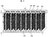
- FIG. 6 shows still another example of the electrolytic cell employed in Examples 1 and 2 of the present invention.
- the example shown in the figure shows an electrolytic cell in which a plurality of electrolytic cells 200 shown in FIGS. 3 and 4 are arranged in parallel.
- 200 is an electrolysis cell
- 224 is a recovery tube for recovering hydrogen generated in the negative electrode chamber of each electrolysis cell
- 225 is a recovery tube for recovering chlorine generated in the positive electrode chamber of each electrolysis cell 200
- 226 is negative electrode electrolysis
- An introduction pipe for water 204, 227 is an introduction pipe for high-concentration waste water introduced into the positive electrode chamber, 228 is a discharge pipe for negative electrode electrolyzed water 204, and 229 is a discharge pipe for high-concentration salt drainage in the positive electrode chamber.
- FIG. 6 shows an example in which the electrolytic cells 200 shown in FIG. 3 are connected in parallel, but the number of cells in parallel is not particularly limited to this, and a large-capacity electrolytic cell such as 80 to 100 cells is used. It is also possible to form.
- the hydrogen recovery pipe 224 is a pipe that connects the recovery port 211 provided in the negative electrode chamber of each electrolysis cell 200 in parallel, and is supplied again as fuel for the gas turbine 12, and if necessary. Exhaust by power from a blower (not shown).
- the chlorine recovery pipe 225 is a pipe connecting the chlorine gas recovery port 210 provided in the positive electrode chamber of each electrolysis cell 200 in parallel, and the coolers 8 and 11, the mist separator 9, the drying tower of FIGS. 1 and 2. 10 is introduced into a chlorination section composed of 10 to form liquid chlorine 21 and finally carried out as a valuable resource. Exhaust by power such as a blower (not shown) if necessary.
- these liquids are supplied to the electrolysis cell 200 by power of a liquid feed pump or the like separately provided through the introduction pipe 226 of the negative electrode electrolyzed water 204 and the introduction pipe 227 of the high-concentration salt drain to be introduced into the positive electrode.
- the negative electrode electrolyzed water 204 is fed to a sodium carbonate or sodium hydrogen carbonate recovery unit by power of a liquid feed pump or the like separately provided through the discharge pipe 228 of the negative electrode electrolyzed water 204, and the high-concentration salt water 203 filled in the positive electrode chamber. Is introduced into the MED 2 or the negative electrode chamber 202 through the discharge pipe 229 of the high concentration salt drainage of the positive electrode.
- FIG. 7 shows still another example of the electrolytic cell employed in each embodiment of the present invention.
- the example shown in the figure shows an electrolytic cell in which a plurality of electrolytic cells 200 having a mechanism for aeration of carbon dioxide shown in FIG. 5 are arranged in parallel.
- reference numeral 230 denotes an introduction pipe for the exhaust gas 25 containing carbon dioxide.
- the introduction pipe 230 is a pipe for connecting the carbon dioxide introduction ports 222 of the electrolysis cells 200 in parallel, and is introduced using power such as a blower (not shown) as necessary.
- the salt drainage treatment apparatus of Example 2 shown in FIG. 2 is used.
- the aeration tank also serves as the negative electrode chamber of the electrolytic tank.
- the setting of the temperature T1 of the aeration tank, the temperature T2 of the precipitation tank, and the temperature T3 of the heat converter differs for each application example.
- Application example 1 The application example which processes the accompanying water discharged
- carbon dioxide gas is introduced in the negative electrode chamber of the electrolytic cell. That is, since the aeration tank is also used as the negative electrode chamber of the electrolytic cell, the aeration tank and the negative electrode chamber of the electrolytic cell are the same.
- Aeration tank temperature T1, precipitation tank temperature T2, and heat exchanger temperature T3 are set to 80 ° C., 20 ° C., and 40 ° C., respectively. This is a condition that satisfies the above (Formula 1), (Formula 2) and (Formula 3) simultaneously.
- Concentrated high-concentration salt drainage is obtained by passing the accompanying water through the RO system and MED.
- concentrations of cation species and anion species were as follows.
- Cationic species Na 59,000 mg / L, Other cations 700 mg / L or less.
- Anion species Cl 77, 200 mg / L, CO 3 181 mg / L, HCO 3 23,000 mg / L, Other anions 700 mg / L or less. Moreover, COD is 300 mg / L or less.
- This salt drainage is put into the positive electrode chamber 201 of the electrolysis cell 200 shown in FIG.
- the negative electrode chamber 202 is charged with 60,000 mg / L sodium carbonate aqueous solution. This is the electrolyzed water concentration after passing through the centrifugal separation mechanism 17 shown in FIG.
- the internal methods of the positive electrode side and the negative electrode side of the electrolysis cell 200 are both 1 m ⁇ 1 m ⁇ 0.01 m, and the volume is 10 L.
- the water temperature at the time of introduction of both is 70 ° C.
- a voltage of 3V and a current of 60A are applied.
- bubbles of chlorine gas are generated from the positive electrode, and electrolysis proceeds.
- sodium ions in the positive electrode chamber 201 move to the negative electrode chamber 202 and the sodium ion concentration in the positive electrode chamber 201 decreases.
- the sodium concentration in the positive electrode chamber 201 and the negative electrode chamber 202 is reduced by the sodium ion concentration adjusting mechanism. Since the difference is 3% or more, this state is set as a steady state, and high-concentration salt drainage is allowed to flow into a stable operation state.
- the sodium ion concentration in the negative electrode chamber 202 becomes 72,000 mg / L. This indicates an increase of 12,000 mg / L sodium ion compared to the initial 60,000 mg / L. This shows that 21,000 mg / L of sodium hydroxide is generated in the negative electrode chamber 202.
- exhaust gas 25 from the gas turbine 12 is blown into the sodium carbonate to form sodium carbonate, and crystallized to be collected in a tank as powder (sodium hydrogen carbonate 27).
- the exhaust gas composition used in this application example is shown below.
- the gas temperature immediately after being discharged from the gas turbine 12 is 330 ° C.
- This gas is sent to the negative electrode chamber of the electrolytic cell 14 through the heat exchanger 13, and the temperature after passing through the heat exchanger 13 is 180 ° C. Since the carbon dioxide concentration is 0.01% or more, it becomes a normal operating condition.
- the sodium carbonate recovered at this time becomes 5.5 kg when the flow rate of the high-concentration salt water passing through the electrolytic cell 14 is 100 L.
- This condition satisfies (Expression 4) in addition to (Expression 1), (Expression 2), and (Expression 3).
- the drainage composition, gas composition, and electrolysis conditions are the same as in Application Example 1.
- the sodium carbonate recovered at this time becomes 6.0 kg when the flow rate of high-concentration drainage water flowing through the electrolytic cell 14 is 100 L.
- This condition satisfies (Expression 4) and (Expression 5) in addition to (Expression 1), (Expression 2), and (Expression 3).
- the sodium carbonate recovered at this time becomes 11.0 kg when the flow rate of high-concentration drainage water flowing through the electrolytic cell 14 is 100 L.
- the sodium carbonate recovered at this time becomes 11.0 kg when the flow rate of high-concentration drainage water flowing through the electrolytic cell 14 is 100 L.
- this invention is not limited to the above-mentioned Example, Various modifications are included.
- the above-described embodiments have been described in detail for easy understanding of the present invention, and are not necessarily limited to those having all the configurations described.
- a part of the configuration of one embodiment can be replaced with the configuration of another embodiment, and the configuration of another embodiment can be added to the configuration of one embodiment.
- Neutralization Tank 110 ... High pressure water pump, 111 ... RO membrane desalination device, 112 ... Chemical cleaning / wastewater treatment device, 113 ... Pressure energy recovery device, 114 ... Backwash device, 115 ... Product gas supply blower, 116 ... MED device, 118 ... Radiating section, 119, 120 ... Ejector, 123 ... Waste heat recovery boiler, 124, 125, 126, 131, 132, 140, 141, 142, 145, 152 ... Liquid feed pump, 127 ... Transformer, 129 ... Scrubber , 130, 134 ... powder separator, 133 ... CO 2 absorber, 135 ... soda bath, 136 ...
- salt concentration sensor in positive electrode chamber 208 '... salt concentration sensor in negative electrode chamber, 210 ... chlorine gas recovery port, 211 ... hydrogen gas discharge port, 212 ... negative electrode electrolyzed water inlet, 213 ... high concentration salt water introduced Mouth, 214 ... Hydrogen gas, 215 ... Negative electrode electrolyzed water outlet, 216 ... Positive electrode high-concentration salt water outlet, 217 ... Water level meter in positive electrode chamber, 218 ... Water level meter in negative electrode chamber, 219 ... Positive electrode terminal, 220 ... Negative electrode Terminal, 22 DESCRIPTION OF SYMBOLS ... Ion exchange membrane, 222 ... Carbon dioxide inlet, 223 ... Carbon dioxide outlet, 224 ...
- Recovery tube for recovering hydrogen generated in the negative electrode chamber 225 ... Recovery tube for recovering chlorine generated in the positive electrode chamber, 226 ... negative electrode electrolyzed water introduction pipe, 227 ... high concentration salt effluent introduction pipe introduced into the positive electrode chamber, 228 ... negative electrode electrolyzed water discharge pipe, 229 ... high concentration salt effluent discharge pipe in the positive electrode compartment, 230 ... introduction of exhaust gas tube.
Landscapes
- Chemical & Material Sciences (AREA)
- Organic Chemistry (AREA)
- Engineering & Computer Science (AREA)
- Water Supply & Treatment (AREA)
- Environmental & Geological Engineering (AREA)
- Hydrology & Water Resources (AREA)
- Life Sciences & Earth Sciences (AREA)
- Materials Engineering (AREA)
- Electrochemistry (AREA)
- Chemical Kinetics & Catalysis (AREA)
- General Chemical & Material Sciences (AREA)
- Inorganic Chemistry (AREA)
- Water Treatment By Electricity Or Magnetism (AREA)
- Electrolytic Production Of Non-Metals, Compounds, Apparatuses Therefor (AREA)
- Heat Treatment Of Water, Waste Water Or Sewage (AREA)
- Removal Of Specific Substances (AREA)
- Treating Waste Gases (AREA)
Applications Claiming Priority (2)
| Application Number | Priority Date | Filing Date | Title |
|---|---|---|---|
| JP2012152244A JP2014014743A (ja) | 2012-07-06 | 2012-07-06 | 塩排水の処理方法及びその処理装置 |
| JP2012-152244 | 2012-07-06 |
Publications (1)
| Publication Number | Publication Date |
|---|---|
| WO2014007033A1 true WO2014007033A1 (fr) | 2014-01-09 |
Family
ID=49881793
Family Applications (1)
| Application Number | Title | Priority Date | Filing Date |
|---|---|---|---|
| PCT/JP2013/066138 Ceased WO2014007033A1 (fr) | 2012-07-06 | 2013-06-12 | Procédé de traitement d'une eau usée saline et dispositifs de traitement correspondants |
Country Status (2)
| Country | Link |
|---|---|
| JP (1) | JP2014014743A (fr) |
| WO (1) | WO2014007033A1 (fr) |
Cited By (5)
| Publication number | Priority date | Publication date | Assignee | Title |
|---|---|---|---|---|
| CN104928716A (zh) * | 2015-05-26 | 2015-09-23 | 南通星球石墨设备有限公司 | 一种淡盐水预处理装置 |
| JPWO2014006741A1 (ja) * | 2012-07-06 | 2016-06-02 | 株式会社日立製作所 | 塩排水の処理方法及び装置 |
| CN115285969A (zh) * | 2022-08-06 | 2022-11-04 | 华南理工大学 | 生物质衍生的氮掺杂硬炭材料及其制备方法和应用 |
| WO2025010355A1 (fr) * | 2023-07-05 | 2025-01-09 | X Development Llc | Procédés de remédiation de déchets et systèmes associés |
| JP2025026682A (ja) * | 2019-10-23 | 2025-02-21 | Agc株式会社 | 混合原料の製造方法、溶融ガラスの製造方法、及びガラス物品の製造方法 |
Families Citing this family (11)
| Publication number | Priority date | Publication date | Assignee | Title |
|---|---|---|---|---|
| KR101571251B1 (ko) * | 2014-09-25 | 2015-11-23 | 한국전력공사 | 중탄산나트륨 제조 장치 및 그 제조 방법 |
| JP6528173B2 (ja) * | 2015-04-02 | 2019-06-12 | 株式会社微酸研 | 電解槽および次亜塩素酸水製造装置 |
| WO2017023029A1 (fr) * | 2015-07-31 | 2017-02-09 | 한국에너지기술연구원 | Réacteur d'électrolyse pour l'élimination de gaz acides présentant une grande efficacité de contact gaz/liquide et procédé associé |
| JP2018035024A (ja) * | 2016-08-30 | 2018-03-08 | クボタ環境サ−ビス株式会社 | 次亜塩素酸ソーダの製造方法及び次亜塩素酸ソーダの製造装置 |
| KR102028709B1 (ko) * | 2019-02-28 | 2019-11-05 | 울산과학기술원 | 이산화탄소 활용 시스템을 이용한 평형수 처리 시스템 |
| KR102025559B1 (ko) * | 2018-12-20 | 2019-09-26 | (주) 테크로스 | 전기분해를 이용한 선박평형수 및 선박 배기 가스 처리 방법 |
| CN109468656B (zh) * | 2019-01-04 | 2020-05-05 | 北京神州瑞霖环境技术研究院有限公司 | 电解前除碳的阳离子隔膜电解槽串联装置及其应用 |
| CN109609971B (zh) * | 2019-01-04 | 2019-12-31 | 北京神州瑞霖环境技术研究院有限公司 | 电解后除碳的阳离子隔膜电解槽串联装置及其应用 |
| WO2021149176A1 (fr) * | 2020-01-22 | 2021-07-29 | 健司 反町 | Méthode de fixation de dioxyde de carbone, méthode de production de dioxyde de carbone fixé, et dispositif de fixation de dioxyde de carbone |
| CN111517556A (zh) * | 2020-05-14 | 2020-08-11 | 逸辰环保科技(厦门)有限公司 | 电镀废水处理工艺及系统 |
| KR102647111B1 (ko) * | 2022-03-03 | 2024-03-13 | (주)테크윈 | 전기분해에 의한 tmah 회수시스템 |
Citations (6)
| Publication number | Priority date | Publication date | Assignee | Title |
|---|---|---|---|---|
| JPS5421997A (en) * | 1977-07-19 | 1979-02-19 | Diamond Shamrock Corp | Method of making alkali matal carbonates |
| JPS5589485A (en) * | 1978-12-26 | 1980-07-07 | Toagosei Chem Ind Co Ltd | Manufacture of potassium bicarbonate |
| JP2008532904A (ja) * | 2005-03-08 | 2008-08-21 | ソルヴェイ(ソシエテ アノニム) | 炭酸ナトリウム結晶を得るための方法 |
| JP2008538738A (ja) * | 2005-03-08 | 2008-11-06 | ソルヴェイ(ソシエテ アノニム) | 塩素誘導体及び炭酸ナトリウムの結晶を共に得るための方法 |
| JP2011000522A (ja) * | 2009-06-17 | 2011-01-06 | Fuji Clean:Kk | 浸出液から酸およびアルカリを製造する方法および装置 |
| WO2012008013A1 (fr) * | 2010-07-12 | 2012-01-19 | 株式会社日立製作所 | Installation de concentration, installation pour la production d'eau douce par concentration et pour la production d'énergie électrique, procédé de concentration et procédé de fonctionnement d'une installation pour la production d'eau douce par concentration et de production d'énergie électrique |
-
2012
- 2012-07-06 JP JP2012152244A patent/JP2014014743A/ja not_active Withdrawn
-
2013
- 2013-06-12 WO PCT/JP2013/066138 patent/WO2014007033A1/fr not_active Ceased
Patent Citations (6)
| Publication number | Priority date | Publication date | Assignee | Title |
|---|---|---|---|---|
| JPS5421997A (en) * | 1977-07-19 | 1979-02-19 | Diamond Shamrock Corp | Method of making alkali matal carbonates |
| JPS5589485A (en) * | 1978-12-26 | 1980-07-07 | Toagosei Chem Ind Co Ltd | Manufacture of potassium bicarbonate |
| JP2008532904A (ja) * | 2005-03-08 | 2008-08-21 | ソルヴェイ(ソシエテ アノニム) | 炭酸ナトリウム結晶を得るための方法 |
| JP2008538738A (ja) * | 2005-03-08 | 2008-11-06 | ソルヴェイ(ソシエテ アノニム) | 塩素誘導体及び炭酸ナトリウムの結晶を共に得るための方法 |
| JP2011000522A (ja) * | 2009-06-17 | 2011-01-06 | Fuji Clean:Kk | 浸出液から酸およびアルカリを製造する方法および装置 |
| WO2012008013A1 (fr) * | 2010-07-12 | 2012-01-19 | 株式会社日立製作所 | Installation de concentration, installation pour la production d'eau douce par concentration et pour la production d'énergie électrique, procédé de concentration et procédé de fonctionnement d'une installation pour la production d'eau douce par concentration et de production d'énergie électrique |
Cited By (5)
| Publication number | Priority date | Publication date | Assignee | Title |
|---|---|---|---|---|
| JPWO2014006741A1 (ja) * | 2012-07-06 | 2016-06-02 | 株式会社日立製作所 | 塩排水の処理方法及び装置 |
| CN104928716A (zh) * | 2015-05-26 | 2015-09-23 | 南通星球石墨设备有限公司 | 一种淡盐水预处理装置 |
| JP2025026682A (ja) * | 2019-10-23 | 2025-02-21 | Agc株式会社 | 混合原料の製造方法、溶融ガラスの製造方法、及びガラス物品の製造方法 |
| CN115285969A (zh) * | 2022-08-06 | 2022-11-04 | 华南理工大学 | 生物质衍生的氮掺杂硬炭材料及其制备方法和应用 |
| WO2025010355A1 (fr) * | 2023-07-05 | 2025-01-09 | X Development Llc | Procédés de remédiation de déchets et systèmes associés |
Also Published As
| Publication number | Publication date |
|---|---|
| JP2014014743A (ja) | 2014-01-30 |
Similar Documents
| Publication | Publication Date | Title |
|---|---|---|
| WO2014007033A1 (fr) | Procédé de traitement d'une eau usée saline et dispositifs de traitement correspondants | |
| JP5865495B2 (ja) | 塩排水の処理方法及び装置 | |
| US4141825A (en) | Desalination process system and by-product recovery | |
| US4083781A (en) | Desalination process system and by-product recovery | |
| CN110923738A (zh) | 一种高温电解海水制备氢气的装置和方法 | |
| WO2014007032A1 (fr) | Procédé et dispositif de traitement d'eaux usées salines | |
| EP3848331B1 (fr) | Méthode de dessalement capable de produire de l'hydrogène | |
| CN110965069A (zh) | 电解水生产高纯氢气和/或氧气的装置和方法 | |
| CN113502485B (zh) | 火电厂电解海水制氢系统和方法 | |
| US8178059B2 (en) | Systems and methods for supplying chlorine to and recovering chlorine from a polysilicon plant | |
| US20240198288A1 (en) | Sustainable desalination systems and methods using recycled brine streams | |
| WO2014006742A1 (fr) | Dispositif de traitement d'eaux usées salines et procédé de traitement de celles-ci | |
| CN116145165B (zh) | 一种电解高盐水制氢系统、电厂储能系统及方法 | |
| EP2824082A1 (fr) | Procédé et appareil pour l'exploitation de l'eau de mer | |
| WO2012085552A1 (fr) | Unité de dessalement et de séquestration de gaz à effet de serre | |
| KR20210010937A (ko) | 수소 생산가능한 담수시스템 | |
| AU2005100007A4 (en) | Process for conversion of high pressure sea water reverse osmosis concentrate discharge (HPSWRO) from sea water desalination plants into Magnesium Chloride (for recovery of Magnesium metal by electrolysis) and sodium Chloride and Hydrogen with cogeneration of Electricity and heat by PEM (proton exchange membrane) Fuel cell | |
| Arias-Sanchez et al. | Perspectives of electrochemical and photocatalytic technologies for the water-energy nexus potential of water splitting of brines | |
| CN111151140B (zh) | 一种浓缩氯碱阳极淡盐水的方法 | |
| CN117303633A (zh) | 一种盐湖卤水中锂钾钠资源综合回收系统及方法 | |
| JP4936454B2 (ja) | 水素製造装置および水素製造方法 | |
| JP2007261931A (ja) | 水素製造装置および水素製造方法 | |
| US20240174527A1 (en) | System for the production of lithium hydroxide (lioh) directly from lithium chloride (lici), without the need for the intermediate production of lithium carbonate or the like | |
| JP3281727B2 (ja) | 重水製造装置 | |
| Kakkar et al. | A comprehensive review on water treatment techniques |
Legal Events
| Date | Code | Title | Description |
|---|---|---|---|
| 121 | Ep: the epo has been informed by wipo that ep was designated in this application |
Ref document number: 13813793 Country of ref document: EP Kind code of ref document: A1 |
|
| NENP | Non-entry into the national phase |
Ref country code: DE |
|
| 122 | Ep: pct application non-entry in european phase |
Ref document number: 13813793 Country of ref document: EP Kind code of ref document: A1 |