WO2014007197A1 - Connecteur - Google Patents
Connecteur Download PDFInfo
- Publication number
- WO2014007197A1 WO2014007197A1 PCT/JP2013/067993 JP2013067993W WO2014007197A1 WO 2014007197 A1 WO2014007197 A1 WO 2014007197A1 JP 2013067993 W JP2013067993 W JP 2013067993W WO 2014007197 A1 WO2014007197 A1 WO 2014007197A1
- Authority
- WO
- WIPO (PCT)
- Prior art keywords
- housing
- connector
- terminal
- mating
- shell
- Prior art date
- Legal status (The legal status is an assumption and is not a legal conclusion. Google has not performed a legal analysis and makes no representation as to the accuracy of the status listed.)
- Ceased
Links
Images




Classifications
-
- H—ELECTRICITY
- H01—ELECTRIC ELEMENTS
- H01R—ELECTRICALLY-CONDUCTIVE CONNECTIONS; STRUCTURAL ASSOCIATIONS OF A PLURALITY OF MUTUALLY-INSULATED ELECTRICAL CONNECTING ELEMENTS; COUPLING DEVICES; CURRENT COLLECTORS
- H01R13/00—Details of coupling devices of the kinds covered by groups H01R12/70 or H01R24/00 - H01R33/00
- H01R13/56—Means for preventing chafing or fracture of flexible leads at outlet from coupling part
-
- H—ELECTRICITY
- H01—ELECTRIC ELEMENTS
- H01R—ELECTRICALLY-CONDUCTIVE CONNECTIONS; STRUCTURAL ASSOCIATIONS OF A PLURALITY OF MUTUALLY-INSULATED ELECTRICAL CONNECTING ELEMENTS; COUPLING DEVICES; CURRENT COLLECTORS
- H01R13/00—Details of coupling devices of the kinds covered by groups H01R12/70 or H01R24/00 - H01R33/00
- H01R13/46—Bases; Cases
- H01R13/533—Bases, cases made for use in extreme conditions, e.g. high temperature, radiation, vibration, corrosive environment, pressure
-
- H—ELECTRICITY
- H01—ELECTRIC ELEMENTS
- H01R—ELECTRICALLY-CONDUCTIVE CONNECTIONS; STRUCTURAL ASSOCIATIONS OF A PLURALITY OF MUTUALLY-INSULATED ELECTRICAL CONNECTING ELEMENTS; COUPLING DEVICES; CURRENT COLLECTORS
- H01R2201/00—Connectors or connections adapted for particular applications
- H01R2201/26—Connectors or connections adapted for particular applications for vehicles
Definitions
- the present invention relates to a connector.
- This invention was completed based on the above situations, and it aims at providing the connector which can prevent that a malfunction arises in the connection with the other party connector by the vibration etc. of an electric wire. To do.
- the present invention is a connector that can be fitted to a mating connector, a housing that can be fitted to a mating housing provided in the mating connector, and a housing that is held by the housing and provided in the mating connector.
- a terminal connecting portion connected to the mating terminal, a terminal provided with a conductor connecting portion connected to the terminal connecting portion, a conductive member drawn out from the inside of the housing, and an inside of the housing
- a stretchable conductor disposed between the terminal and the conductive member, extending toward the conductive member from a portion where the conductor connecting portion is connected, and stretchable in the extending direction;
- examples of the stretchable conductor include a braided wire obtained by knitting a thin metal wire in a mesh shape.
- examples of the conductive member include an electric wire in which a core wire formed by twisting copper strands is covered with an insulating coating, and a conductive plate such as a bus bar obtained by punching a copper plate into a predetermined shape.
- the welding portion is fixed to the housing. In this way, since the welded portion is fixed to the housing, even if vibration of the conductive member occurs, it is possible to block the influence of vibration or the like at the portion fixed to the housing, and more reliably. In addition, it is possible to prevent a problem in connection with the mating connector due to vibration on the conductive member side or the like.
- the welded portion has a screw hole through which a bolt passes, and is fixed to the housing through the bolt through the bolt. If it does in this way, since a welding part can be bolted to a housing, a welding part can be firmly fixed to a housing.
- the mating connector is housed in a case of the device, and a through hole is formed in the case. A portion of the housing that protrudes into the case through the through hole is the mating connector. Mates with side housing. If it does in this way, since a housing can be penetrated and supported by the penetration hole of a case, it can control that a vibration etc. are transmitted to the other party connector via a housing from a welding part.
- a shield shell that covers the housing and is fixed to the housing and screwed to the case is provided. If it does in this way, a housing can be fixed to a case via a shield shell. Therefore, it is possible to further suppress vibrations from being transmitted from the welded portion to the mating connector.
- the present invention it is possible to prevent the connector from being defective in connection with the mating connector due to electric wire vibration or the like.
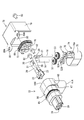
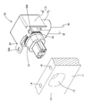
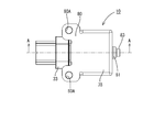
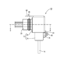
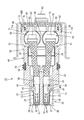
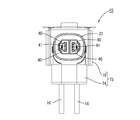
- the perspective view which shows the state in which the connector of embodiment is attached to the to-be-attached part The perspective view which shows the state from which the connector is attached to the to-be-attached part from the back side Connector exploded perspective view
- the connector 10 of the embodiment will be described with reference to FIGS.
- the connector 10 of this embodiment is attached to a shield case 11 of a device (for example, an inverter or a motor of a vehicle such as a hybrid vehicle or an electric vehicle).
- a device for example, an inverter or a motor of a vehicle such as a hybrid vehicle or an electric vehicle.
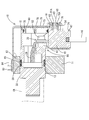
- the vertical direction will be described with reference to FIG. 6, with the left side (fitting direction with the mating connector) in FIG. 6 as the front and the right side as the rear.
- the device is a device in which a device body (not shown) is accommodated in a shield case 11 made of a conductive material (the left side of the shield case 11 in FIG. 6 is the inside of the shield case 11). It has the to-be-attached part 12 to which the connector 10 is attached.
- a part of shield case 11 is shown in figure, and the other part is abbreviate
- the mounted portion 12 includes an oval through hole 13 that is long in the left-right direction and a pair of left and right mounting holes 14 provided on the upper end surface of the shield case 11.
- the mounting hole 14 has a thread groove on the inner peripheral surface.
- a mating connector CN (see FIG. 6) is arranged at a position facing the connector 10 inside the shield case 11.
- the connector 10 includes a housing 33 that can be fitted into a mating housing provided in the mating connector CN, a terminal 23 held by the housing 33, and a stretchable conductor connected to the terminal 23. 29, a wire 16 connected to the stretchable conductor 29, a shield shell 73 covering the housing 33, and the like.
- the electric wire 16 is a covered electric wire in which a core wire formed by twisting copper strands is covered with an insulating coating, and the insulating coating (insulating layer) is peeled off at the terminal portion, and the core wire is exposed.
- the end portion of the electric wire 16 has a flat plate shape. The electric wire 16 is pulled out from the inside of the housing 33 and connected to a device such as a battery.
- the terminal 23 has a terminal connection portion 24 connected to the counterpart terminal of the counterpart connector CN, and a conductor connection portion 28 is provided continuously from the terminal connection portion 24. It is said that.
- the terminal connection portion 24 has a pair of elastic contact pieces 26 formed inside a cylindrical portion having a rectangular tube shape.
- the pair of elastic contact pieces 26 are folded back and extended rearward so as to face each other at the front end opening edge of the terminal connection portion 24.
- the terminal connection portion 24 is formed with a lance locking portion 27 that can lock the lance 42.
- the conductor connecting portion 28 is an open barrel type crimping portion having a pair of barrel pieces.
- the conductor connection portion 28 is crimped and fixed to the stretchable conductor 29.
- the stretchable conductor 29 is a flexible conductor, and for example, a braided wire in which fine metal wires made of aluminum or aluminum alloy are knitted in a mesh shape is used.
- the stretchable conductor 29 is disposed between the terminal 23 and the electric wire 16 inside the housing 33, and extends toward the electric wire 16 from the portion where the conductor connecting portion 28 is crimped and connected. It can be expanded and contracted in both directions.
- the stretchable conductor 29 is bent in a substantially L shape at the rear edge thereof, and a portion extending downward from the bent portion has a flat plate shape.
- wire core wires (stranded wires, etc.) Can be used.
- the housing 33 is L-shaped in a side view, and extends in a direction substantially orthogonal to the first tube portion 47 in which the electric wire 16 is accommodated, and the first tube portion 47. And the second cylindrical portion 56 in which the stretchable conductor 29 is accommodated, and a connecting portion 60 that connects the first cylindrical portion 47 and the second cylindrical portion 56.
- the first tube portion 47 has a pair of left and right first storage chambers 49 as shown in FIG.
- a circular cavity 50 penetrates in the vertical direction, and an intermediate portion in the horizontal direction is partitioned by a partition wall 48.
- a rubber ring 51 that is in close contact with the outer periphery of each electric wire 16 is disposed on the inner peripheral surface (inner wall) of the first storage chamber 49.
- a retainer 52 that holds the rubber ring 51 so as not to be displaced is attached to the lower side of the rubber ring 51.
- the retainer 52 is configured by fitting a plurality of divided members 52A and 52A.
- a retaining portion 53 that protrudes from the inner wall of the first storage chamber 49 to prevent the rubber ring 51 from slipping out is provided.
- the 2nd cylinder part 56 has the terminal accommodating part 35 in which the terminal 23 is accommodated, as shown in FIG.
- the terminal accommodating portion 35 has an oval outer periphery that is long in the left-right direction, and the front side has a stepped shape with an outer diameter reduced to protrude forward.
- a pair of left and right second storage chambers 37 are formed inside the terminal storage portion 35.
- the pair of second storage chambers 37 has an intermediate portion partitioned by a partition wall 38, and a cavity 39 penetrates the second storage chamber 37 in the front-rear direction.
- the cavity 39 communicates with the cavity 50 of the first tube portion 47.
- a front stop wall 40 rising from the inner wall of the cavity 39 is formed at the front end of the second storage chamber 37, and a terminal insertion hole into which the male counterpart terminal of the counterpart connector CN is inserted into the front stop wall 40. 41 is formed to penetrate therethrough.
- the front stop wall 40 is provided in front of the terminal 23 and restricts the movement of the terminal 23 to the front.
- the terminal insertion hole 41 opens with a size that allows insertion of a tab-shaped male terminal. The male terminal is inserted into the terminal insertion hole 41 in a vertical orientation in which the contact surface with the elastic contact piece 26 extends in the vertical direction.
- a lance 42 that protrudes in a cantilevered manner is provided.
- the lance 42 is provided with a locking projection 43 that is locked to the lance locking portion 27 of the terminal 23.
- An opening 56B is formed in the rear end portion of the second cylindrical portion 56 so as to penetrate in the front-rear direction, and a mounting groove 59 for mounting the seal ring 85 is provided in an annular shape on the outer periphery of the second cylindrical portion 56.
- a cover attachment portion 67 to which the protective cover 69 can be attached is formed in the opening portion 56B of the second cylinder portion 56.
- a cover locking convex portion 68 is formed on the outer surface side of the cover mounting portion 67.
- the cover locking convex portion 68 is formed in a stepped shape in which the front end rises vertically from the outer surface of the second cylindrical portion 56, and has a tapered inclined surface whose protruding dimension decreases from the stepped portion toward the rear.
- the protective cover 69 has an oval shape that is long in the left-right direction, and an annular portion 70 is formed on the periphery of an oval plate-like portion that closes the opening 56 ⁇ / b> B of the second cylindrical portion 56.
- the inside is reinforced by a lattice-shaped reinforcing portion.
- a rubber ring 72 is attached to the outer periphery of the annular portion 70.
- a locking frame 71 protruding forward is formed integrally with the annular portion 70 on the radially outer side of the annular portion 70.
- the locking frame 71 has a rectangular locking hole 71A formed therein, and the cover locking projection 68 is locked to the inner wall of the locking hole 71A from the rear.
- the shield shell 73 is made of a metal such as aluminum or an aluminum alloy. As shown in FIG. 3, the shield shell 73 includes a first shell 74 that covers the lower side of the housing 33 and a second shell 78 that covers the upper side of the housing 33. Have.
- the first shell 74 has an oval cylindrical shape that is long in the left-right direction, and includes a cylindrical portion 75 and a fastened piece 76 that extends upward from the cylindrical portion 75.
- the fastened piece 76 extends upward from the back surface of the cylindrical portion 75, and a circular screw hole 76 ⁇ / b> A is formed through the central portion of the fastened piece 76.
- the second shell 78 is attached to the attachment portion 12 of the shield case 11 connected to the shield portion 79 formed in a concave shape that covers the housing 33 from above and behind, and the upper surface of the shield portion 79.
- the mounting part 80 and the to-be-fastened piece 81 which protrudes below in a row from the rear edge of the shield part 79 are provided.
- a circular attachment hole 80 ⁇ / b> A is formed in the attachment portion 80.
- a pair of left and right mounting holes 80 ⁇ / b> A are provided corresponding to the pair of left and right mounting portions 80.
- the fastened piece 76 of the first shell 74 and the fastened piece 81 of the second shell 78 are disposed so as to overlap each other, and the screw hole 76A of the first shell 74 and the screw hole 81A of the second shell 78 have the same shape. Arranged coaxially.
- Each of the fastened pieces 76 and 81 is disposed in the shell fixing portion 54 of the first cylindrical portion 47 and can come into contact with the collar 62 press-fitted into the shell fixing portion 54.
- a screw hole 63 is formed inside the collar 62.
- the first shell 74 and the second shell 78 are electrically connected by passing the shaft portion of the bolt 83 through the screw holes 76A and 81A and fastening the screw holes 63 to the screw holes 63 of the collar 62 together.
- the housing 33 is fixed to the shield case 11 via the shield shell 73.
- the electric wire 16 and the stretchable conductor 29 are electrically connected by the welded portion 20.
- the welded portion 20 has a flat plate shape as a whole, and is welded integrally by overlapping and resistance welding the upper end plate-like portion of the electric wire 16 and the rear end plate-like portion of the stretchable conductor 29.
- a pair of left and right welding portions 20 are provided to face each electric wire 16.
- the welding means between the upper end plate-like portion of the electric wire 16 and the rear end plate-like portion of the stretchable conductor 29 may be a welding means other than resistance welding, for example, ultrasonic welding or other known welding means. It is good.
- a screw hole 21 is formed in the center of the welded portion 20 so as to penetrate in the thickness direction.
- the coupling portion 60 of the housing 33 is provided with a bolt fastening portion 61 that fixes the welding portion 20 to the housing 33 by tightening a bolt 82.
- a pair of left and right bolt fastening portions 61 are provided corresponding to the pair of welded portions 20.
- the bolt 82 is a male screw composed of a polygonal head and a shaft portion having a thread groove, and is fastened by passing the shaft portion through the screw hole 21 of the welded portion 20 and tightening the bolt fastening portion 61.
- a screw groove is formed on the inner peripheral surface of the screw hole of the bolt fastening portion 61, and this screw groove is screwed with a screw groove formed on the outer peripheral surface of the shaft portion of the bolt 82. Thereby, the welding part 20 is fixed to the bolt fastening part 61 of the housing 33.
- This embodiment is configured as described above, and a method for manufacturing the connector 10 will be described.
- the two electric wires 16 After passing the two electric wires 16 through the rubber ring 51 and the first shell 74, they are inserted into the cavity 50 of the first tube portion 47 from below, and the end portions of the electric wires 16 are formed into a flat plate shape.
- the front end portion of the stretchable conductor 29 is placed on the conductor connection portion 28 of the terminal 23, and a pair of barrel pieces provided in the conductor connection portion 28 is crimped from both sides to be crimped to the front end portion of the stretchable conductor 29.
- the rear end portion of the stretchable conductor 29 is bent downward in a substantially L shape to form a flat plate shape.
- the welding part 20 is formed by mutually superposing the rear-end plate-shaped part of the elastic conductor 29, and the upper-end plate-shaped part of the electric wire 16, and performing resistance welding.
- the terminal 23 is inserted into the cavity 39 of the second cylindrical portion 56 from the rear and the terminal 23 is inserted to the normal position of the cavity 39, the lance 42 is restored and is locked to the lance locking portion 27. As a result, the terminal 23 is held in a retaining state. Further, the rubber ring 51 is fitted from the opening 47A at the lower end of the first cylindrical portion 47, and the retainer 52 is mounted so as to hold the rubber ring 51 below the rubber ring 51. Thereafter, as shown in FIG. 6, the welded portion 20 is placed on the bolt fastening portion 61 of the housing 33, and the welded portion 20 is fixed to the housing 33 by fastening the bolt 82.
- the protective cover 69 is attached to the cover attaching portion 67, and the locking frame 71 is locked to the cover locking convex portion 68. Thereby, the opening part 56B of the 2nd cylinder part 56 is obstruct
- the housing 33 is fitted into the through hole 13 of the shield case 11.
- a part of the housing 33 protrudes into the shield case 11, and this protruding part fits into the mating housing provided in the mating connector CN, and the mounting portion 80 of the shield shell 73 is shielded. It is arranged so as to overlap the attached portion 12 of the case 11.
- the shield shell 73 is fixed to the shield case 11 by passing the attachment screw 84 through the attachment hole 80 ⁇ / b> A and fastening to the shield case 11.
- the welding part 20 is fixed to the shield case 11 via the housing 33 and the shield shell 73.
- the elastic conductor 29 can absorb the influence of the vibration of the electric wire 16 and the influence of the vibration of the electric wire 16 is transferred from the terminal 23 to the counterpart terminal of the counterpart connector. It can suppress being given. Therefore, it is possible to prevent a problem in connection with the mating connector due to vibration of the electric wire 16 or the like.
- the welded portion 20 has a screw hole 21 through which the bolt 82 is passed, and is fixed to the screw hole 21 through the bolt 82 and fastened to the housing 33. In this way, the welded portion 20 can be bolted to the housing 33, so that the welded portion 20 can be firmly fixed to the housing 33.
- the mating connector CN is housed inside the shield case 11 of the device.
- the shield case 11 is formed with a through hole 13, and the shield case penetrates the through hole 13 in the housing 33. 11 protrudes into the mating housing. If it does in this way, since housing 33 can penetrate through penetration hole 13 of shield case 11, and it can support, it can control that a vibration etc. are transmitted to other party connector CN via housing 33 from welding part 20.
- a shield shell 73 that covers the housing 33 and is fixed to the housing 33 and screwed to the shield case 11 is provided. In this way, the housing 33 can be fixed to the shield case 11 via the shield shell 73. Therefore, it is possible to further suppress vibrations and the like from being transmitted from the welded portion 20 to the mating connector CN.
- the welded portion 20 is fixed to the housing 33 in the above embodiment, the welded portion 20 may not be fixed to the housing 33 according to the present invention.
- the inside of the housing 33 is fixed with resin filling (for example, by potting). May be.
- the connector 10 at the terminal portion of the electric wire 16 attached to the connector on the device side provided in the device including the inverter, motor, etc. of the vehicle is not limited to this, but other than the inverter device and the motor. It is good also as a connector of the terminal part of the electric wire attached to another apparatus.
- the shield shell 73 is composed of the first shell 74 and the second shell 78, but is not limited thereto. For example, you may make it cover the back side of the housing 33 with the shield shell which consists of one member.
- the number of the electric wires 16 is two. However, the number is not limited to this, and may be one, or three or more.
- first shell 74 and the second shell 78 are fastened with one bolt 83.
- the present invention is not limited to this, and the first shell 74 and the second shell 78 are different bolts.
- the housing 33 may be fastened.
- the connector 10 is attached to the shield case 11.
- the present invention is not limited to this.
- the connector 10 may be attached to a case having no shield function.
- the bolt 82 is directly fastened to the bolt fastening portion 61 of the housing 33 in the above embodiment, the present invention is not limited to this.
- the welded portion 20 may be fixed to the housing 33 by embedding and fixing a nut in the housing, and bolting the nut fixed to the housing.
Landscapes
- Details Of Connecting Devices For Male And Female Coupling (AREA)
Applications Claiming Priority (2)
| Application Number | Priority Date | Filing Date | Title |
|---|---|---|---|
| JP2012-149127 | 2012-07-03 | ||
| JP2012149127A JP2014011134A (ja) | 2012-07-03 | 2012-07-03 | コネクタ |
Publications (1)
| Publication Number | Publication Date |
|---|---|
| WO2014007197A1 true WO2014007197A1 (fr) | 2014-01-09 |
Family
ID=49881953
Family Applications (1)
| Application Number | Title | Priority Date | Filing Date |
|---|---|---|---|
| PCT/JP2013/067993 Ceased WO2014007197A1 (fr) | 2012-07-03 | 2013-07-01 | Connecteur |
Country Status (2)
| Country | Link |
|---|---|
| JP (1) | JP2014011134A (fr) |
| WO (1) | WO2014007197A1 (fr) |
Cited By (3)
| Publication number | Priority date | Publication date | Assignee | Title |
|---|---|---|---|---|
| US9620891B2 (en) | 2015-03-18 | 2017-04-11 | Yazaki Corporation | Connector for preventing force transmission |
| JPWO2021124491A1 (fr) * | 2019-12-18 | 2021-06-24 | ||
| EP4494918A4 (fr) * | 2022-03-14 | 2025-07-09 | Jilin Zhong Ying High Tech Co Ltd | Structure de connexion flexible de connecteur et véhicule |
Families Citing this family (3)
| Publication number | Priority date | Publication date | Assignee | Title |
|---|---|---|---|---|
| CN107112682B (zh) | 2014-10-08 | 2019-10-08 | 株式会社自动网络技术研究所 | 连接器 |
| JP6575340B2 (ja) * | 2015-12-09 | 2019-09-18 | 住友電装株式会社 | コネクタ |
| JP2022136779A (ja) * | 2021-03-08 | 2022-09-21 | 株式会社オートネットワーク技術研究所 | コネクタ |
Citations (3)
| Publication number | Priority date | Publication date | Assignee | Title |
|---|---|---|---|---|
| JP2011009092A (ja) * | 2009-06-26 | 2011-01-13 | Yazaki Corp | 待ち受けコネクタ |
| WO2011016272A1 (fr) * | 2009-08-03 | 2011-02-10 | 矢崎総業株式会社 | Connecteur |
| WO2011055806A1 (fr) * | 2009-11-06 | 2011-05-12 | 矢崎総業株式会社 | Bloc terminal inverseur pour carter de moteur |
Family Cites Families (2)
| Publication number | Priority date | Publication date | Assignee | Title |
|---|---|---|---|---|
| JP2005100850A (ja) * | 2003-09-25 | 2005-04-14 | Fujikura Ltd | 端子金具の組付け構造 |
| JP5194609B2 (ja) * | 2007-07-26 | 2013-05-08 | 住友電装株式会社 | 機器用コネクタ |
-
2012
- 2012-07-03 JP JP2012149127A patent/JP2014011134A/ja active Pending
-
2013
- 2013-07-01 WO PCT/JP2013/067993 patent/WO2014007197A1/fr not_active Ceased
Patent Citations (3)
| Publication number | Priority date | Publication date | Assignee | Title |
|---|---|---|---|---|
| JP2011009092A (ja) * | 2009-06-26 | 2011-01-13 | Yazaki Corp | 待ち受けコネクタ |
| WO2011016272A1 (fr) * | 2009-08-03 | 2011-02-10 | 矢崎総業株式会社 | Connecteur |
| WO2011055806A1 (fr) * | 2009-11-06 | 2011-05-12 | 矢崎総業株式会社 | Bloc terminal inverseur pour carter de moteur |
Cited By (5)
| Publication number | Priority date | Publication date | Assignee | Title |
|---|---|---|---|---|
| US9620891B2 (en) | 2015-03-18 | 2017-04-11 | Yazaki Corporation | Connector for preventing force transmission |
| JPWO2021124491A1 (fr) * | 2019-12-18 | 2021-06-24 | ||
| WO2021124491A1 (fr) * | 2019-12-18 | 2021-06-24 | トヨタ自動車株式会社 | Connecteur latéral de fil électrique |
| JP7273189B2 (ja) | 2019-12-18 | 2023-05-12 | トヨタ自動車株式会社 | 電線側コネクタ |
| EP4494918A4 (fr) * | 2022-03-14 | 2025-07-09 | Jilin Zhong Ying High Tech Co Ltd | Structure de connexion flexible de connecteur et véhicule |
Also Published As
| Publication number | Publication date |
|---|---|
| JP2014011134A (ja) | 2014-01-20 |
Similar Documents
| Publication | Publication Date | Title |
|---|---|---|
| CN103457064B (zh) | 连接器 | |
| CN103579870B (zh) | 连接器 | |
| US9312626B2 (en) | Shield connector | |
| US9472893B1 (en) | Connector | |
| JP6024991B2 (ja) | コネクタおよびハウジング | |
| WO2014007197A1 (fr) | Connecteur | |
| JP6036653B2 (ja) | シールドコネクタ | |
| JP2014038793A (ja) | コネクタ | |
| EP2618428A1 (fr) | Connecteur de dispositif et procédé de connexion | |
| WO2014061727A1 (fr) | Connecteur blindé | |
| JP6818244B2 (ja) | コネクタ | |
| JP5776665B2 (ja) | シールドコネクタ | |
| JP5170013B2 (ja) | シールドコネクタ | |
| JP2014203537A (ja) | シールドコネクタ | |
| JP5772386B2 (ja) | シールド部材及びシールド導電体 | |
| JP2007103044A (ja) | シールドコネクタ | |
| WO2016181792A1 (fr) | Connecteur et structure de connexion de connecteur | |
| WO2019138829A1 (fr) | Faisceau de fils blindés, élément de blindage et procédé de fabrication d'un faisceau de fils blindés | |
| JP2020087582A (ja) | シールドコネクタ | |
| JP2011228017A (ja) | コネクタ | |
| JP7485703B2 (ja) | コネクタ | |
| JP2005129356A (ja) | シールドコネクタ | |
| JP6807025B2 (ja) | コネクタ | |
| KR100803438B1 (ko) | 실드전극 연결수단 | |
| WO2023136013A1 (fr) | Structure de connexion de borne, connecteur, et conducteur de connexion |
Legal Events
| Date | Code | Title | Description |
|---|---|---|---|
| 121 | Ep: the epo has been informed by wipo that ep was designated in this application |
Ref document number: 13813718 Country of ref document: EP Kind code of ref document: A1 |
|
| NENP | Non-entry into the national phase |
Ref country code: DE |
|
| 122 | Ep: pct application non-entry in european phase |
Ref document number: 13813718 Country of ref document: EP Kind code of ref document: A1 |