WO2014007294A1 - 車載装置 - Google Patents
車載装置 Download PDFInfo
- Publication number
- WO2014007294A1 WO2014007294A1 PCT/JP2013/068274 JP2013068274W WO2014007294A1 WO 2014007294 A1 WO2014007294 A1 WO 2014007294A1 JP 2013068274 W JP2013068274 W JP 2013068274W WO 2014007294 A1 WO2014007294 A1 WO 2014007294A1
- Authority
- WO
- WIPO (PCT)
- Prior art keywords
- deposit
- unit
- removal
- vehicle
- predetermined number
- Prior art date
- Legal status (The legal status is an assumption and is not a legal conclusion. Google has not performed a legal analysis and makes no representation as to the accuracy of the status listed.)
- Ceased
Links
Images


Classifications
-
- B—PERFORMING OPERATIONS; TRANSPORTING
- B60—VEHICLES IN GENERAL
- B60S—SERVICING, CLEANING, REPAIRING, SUPPORTING, LIFTING, OR MANOEUVRING OF VEHICLES, NOT OTHERWISE PROVIDED FOR
- B60S1/00—Cleaning of vehicles
- B60S1/02—Cleaning windscreens, windows or optical devices
- B60S1/04—Wipers or the like, e.g. scrapers
- B60S1/06—Wipers or the like, e.g. scrapers characterised by the drive
- B60S1/08—Wipers or the like, e.g. scrapers characterised by the drive electrically driven
- B60S1/0818—Wipers or the like, e.g. scrapers characterised by the drive electrically driven including control systems responsive to external conditions, e.g. by detection of moisture, dirt or the like
- B60S1/0822—Wipers or the like, e.g. scrapers characterised by the drive electrically driven including control systems responsive to external conditions, e.g. by detection of moisture, dirt or the like characterized by the arrangement or type of detection means
- B60S1/0833—Optical rain sensor
- B60S1/0844—Optical rain sensor including a camera
- B60S1/0848—Cleaning devices for cameras on vehicle
-
- B—PERFORMING OPERATIONS; TRANSPORTING
- B60—VEHICLES IN GENERAL
- B60S—SERVICING, CLEANING, REPAIRING, SUPPORTING, LIFTING, OR MANOEUVRING OF VEHICLES, NOT OTHERWISE PROVIDED FOR
- B60S1/00—Cleaning of vehicles
- B60S1/02—Cleaning windscreens, windows or optical devices
- B60S1/46—Cleaning windscreens, windows or optical devices using liquid; Windscreen washers
- B60S1/48—Liquid supply therefor
- B60S1/481—Liquid supply therefor the operation of at least part of the liquid supply being controlled by electric means
- B60S1/485—Liquid supply therefor the operation of at least part of the liquid supply being controlled by electric means including control systems responsive to external conditions, e.g. by detection of moisture, dirt or the like
-
- B—PERFORMING OPERATIONS; TRANSPORTING
- B60—VEHICLES IN GENERAL
- B60S—SERVICING, CLEANING, REPAIRING, SUPPORTING, LIFTING, OR MANOEUVRING OF VEHICLES, NOT OTHERWISE PROVIDED FOR
- B60S1/00—Cleaning of vehicles
- B60S1/02—Cleaning windscreens, windows or optical devices
- B60S1/56—Cleaning windscreens, windows or optical devices specially adapted for cleaning other parts or devices than front windows or windscreens
-
- H—ELECTRICITY
- H04—ELECTRIC COMMUNICATION TECHNIQUE
- H04N—PICTORIAL COMMUNICATION, e.g. TELEVISION
- H04N23/00—Cameras or camera modules comprising electronic image sensors; Control thereof
- H04N23/80—Camera processing pipelines; Components thereof
- H04N23/81—Camera processing pipelines; Components thereof for suppressing or minimising disturbance in the image signal generation
- H04N23/811—Camera processing pipelines; Components thereof for suppressing or minimising disturbance in the image signal generation by dust removal, e.g. from surfaces of the image sensor or processing of the image signal output by the electronic image sensor
-
- B—PERFORMING OPERATIONS; TRANSPORTING
- B05—SPRAYING OR ATOMISING IN GENERAL; APPLYING FLUENT MATERIALS TO SURFACES, IN GENERAL
- B05B—SPRAYING APPARATUS; ATOMISING APPARATUS; NOZZLES
- B05B12/00—Arrangements for controlling delivery; Arrangements for controlling the spray area
- B05B12/08—Arrangements for controlling delivery; Arrangements for controlling the spray area responsive to condition of liquid or other fluent material to be discharged, of ambient medium or of target ; responsive to condition of spray devices or of supply means, e.g. pipes, pumps or their drive means
-
- B—PERFORMING OPERATIONS; TRANSPORTING
- B60—VEHICLES IN GENERAL
- B60S—SERVICING, CLEANING, REPAIRING, SUPPORTING, LIFTING, OR MANOEUVRING OF VEHICLES, NOT OTHERWISE PROVIDED FOR
- B60S1/00—Cleaning of vehicles
- B60S1/02—Cleaning windscreens, windows or optical devices
- B60S1/04—Wipers or the like, e.g. scrapers
- B60S1/06—Wipers or the like, e.g. scrapers characterised by the drive
- B60S1/08—Wipers or the like, e.g. scrapers characterised by the drive electrically driven
- B60S1/0818—Wipers or the like, e.g. scrapers characterised by the drive electrically driven including control systems responsive to external conditions, e.g. by detection of moisture, dirt or the like
- B60S1/0822—Wipers or the like, e.g. scrapers characterised by the drive electrically driven including control systems responsive to external conditions, e.g. by detection of moisture, dirt or the like characterized by the arrangement or type of detection means
- B60S1/0833—Optical rain sensor
- B60S1/0844—Optical rain sensor including a camera
-
- G—PHYSICS
- G08—SIGNALLING
- G08G—TRAFFIC CONTROL SYSTEMS
- G08G1/00—Traffic control systems for road vehicles
- G08G1/16—Anti-collision systems
- G08G1/166—Anti-collision systems for active traffic, e.g. moving vehicles, pedestrians, bikes
-
- G—PHYSICS
- G08—SIGNALLING
- G08G—TRAFFIC CONTROL SYSTEMS
- G08G1/00—Traffic control systems for road vehicles
- G08G1/16—Anti-collision systems
- G08G1/167—Driving aids for lane monitoring, lane changing, e.g. blind spot detection
-
- H—ELECTRICITY
- H04—ELECTRIC COMMUNICATION TECHNIQUE
- H04N—PICTORIAL COMMUNICATION, e.g. TELEVISION
- H04N23/00—Cameras or camera modules comprising electronic image sensors; Control thereof
- H04N23/50—Constructional details
- H04N23/51—Housings
Definitions
- the present invention relates to an in-vehicle device.
- Patent Document 1 An imaging apparatus that can confirm whether foreign matter has been removed from an optical member has been considered (Patent Document 1).
- An object of the present invention is to suitably clean a photographing lens of a vehicle-mounted camera.
- the in-vehicle device outputs a control signal to the cleaning control unit that controls the adhering substance removing unit of the plurality of methods for removing the adhering substance adhering to the photographing lens of the in-vehicle camera.
- An in-vehicle device and when the input vehicle speed is equal to or higher than a predetermined vehicle speed, an adhering matter detection unit that detects adhering matter adhering to the photographing lens from a photographed image output from the in-vehicle camera, and a plurality of methods
- the selection unit that selects the deposit removal unit of the first method from among the deposit removal unit and the photographed image is used to photograph by the removal operation by the deposit removal unit of the first method selected by the selection unit
- a removal determining unit that determines whether or not the attached matter has been removed from the lens, and the selecting unit is configured to perform the first method when the removal determining unit determines that the attached matter is not removed from the photographing lens.
- a plurality of removal operations using each of the plurality of deposit removal parts correspond to each of the plurality of deposit removal parts.
- a mask image storage unit for storing an image of the non-removed deposit as a mask image when the removal determining unit determines that the deposit has not been removed from the photographic lens after the predetermined number of times.
- the kimono detection unit preferably does not detect the deposits stored as the mask image in the mask image storage unit.
- the deposit removal part of the first method wipes off the deposit using compressed air
- the deposit removal part of the second method Removes the deposits using a washer liquid
- the selection unit removes the deposits of the first method when the number of removal operations of the deposit removal unit of the first method is equal to or less than the first predetermined number of times.
- the number of removal operations of the deposit removal unit of the first method is greater than the first predetermined number of times
- the number of removal operations of the deposit removal unit of the second method is equal to or less than the second predetermined number of times.
- the plurality of methods of removing the deposits further includes a third method of removing deposits using a wiper.
- the selecting unit selects the deposit removing unit of the first method when the number of removal operations of the deposit removing unit of the first method is equal to or less than the first predetermined number of times, and removes the deposit of the first method.
- the attachment removal part of the second method is selected
- the number of deposit removing parts in the first method is larger than the first predetermined number of times, and the number of deposit removing parts in the second method is larger than the second predetermined number of times.
- the deposit removal part of the third method is selected and the first method
- the number of the kimono removing unit is larger than the first predetermined number
- the number of the deposit removing unit of the second method is larger than the second predetermined number
- the number of the deposit removing unit of the third method is the third predetermined number.
- the removal determination unit is a type of the deposit removed by the removal operation by the deposit removal unit of the first method selected by the selection unit.
- the removal determination unit is a type of the deposit removed by the removal operation by the deposit removal unit of the first method selected by the selection unit.
- the deposit removed by the removal operation of the deposit removal unit of the first method is discriminated as the deposit of water droplets, and the attachment removed by the removal operation of the deposit removal unit of the second method is determined. It is preferable to discriminate the kimono from mud deposits and to discriminate the deposits removed by the removal operation of the deposit removal unit of the third method as deposits of water droplets.
- the state of the imaging lens of the in-vehicle camera can be appropriately estimated, and the presence of attached dirt can be confirmed.
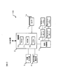
- FIG. 1 is a block configuration diagram of an in-vehicle device 100 according to an embodiment of the present invention.
- the in-vehicle device 100 shown in FIG. 1 is used by being mounted on a vehicle, and includes a camera 1, a control unit 2, an alarm output unit 3, an operating state notification unit 4, and a light shielding plate 1a attached thereto.
- the cleaning control unit 5, the air pump 6, the washer pump 7, the air nozzle 8, and the washer nozzle 9 are provided.
- the camera 1 is installed toward the rear of the vehicle, and captures images in a shooting area including the road surface behind the vehicle at predetermined time intervals.
- an image sensor such as a CCD or a CMOS is used.
- a captured image acquired by the camera 1 is output from the camera 1 to the control unit 2.
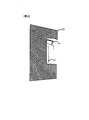
- FIG. 2 is a diagram showing a shooting region and a light shielding region of the camera 1, and shows a state in which the camera 1 is viewed from the lateral direction.
- a light shielding area is formed by masking an upper part of the photographing area of the camera 1 with a light shielding plate 1a.
- the camera 1 captures an image including a road surface behind the vehicle in an imaging region other than the light shielding region.
- the shooting area (view angle, shooting angle of view) of the camera 1 is set to be relatively wide so that the road surface behind the vehicle can be shot in a sufficiently wide range in the left-right direction. Unnecessary light from the background or the like is also incident on the camera 1. Therefore, in order to block such unwanted incident light on the camera 1, a light shielding region is provided by the light shielding plate 1a.
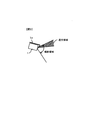
- FIG. 3 is a diagram illustrating an example of an attachment position of the camera 1.
- a number plate 21 is installed on the vehicle body 20 at the rear portion of the host vehicle.
- the camera 1 is mounted obliquely downward at a position directly above the number plate 21, and a light shielding plate 1a is installed thereon.
- the attachment position shown here is an example to the last, you may attach the camera 1 to another position. As long as the road surface behind the vehicle can be photographed within an appropriate range, the attachment position of the camera 1 may be determined in any manner.
- the control unit 2 includes a RAM 10, a ROM 11, and a CPU 12, stores captured images from the camera 1 in the RAM 10, performs predetermined image processing using these captured images, and performs various controls according to the processing results. I do.
- various functions called LDW (Lane (Departure Warning), PED (Pedestrian Detection), RSR (Road Sign Recognition), and IMD (Image Diagnosis) are realized by the control performed by the control unit 2.
- LDW is a function that outputs a warning when the host vehicle is likely to deviate from the traveling lane by detecting a white line (lane boundary line, roadway outer line, center line, etc.) on the road surface from the captured image.
- the PED is a function that informs the driver of the presence of a pedestrian on the path of the vehicle by detecting a person shape from the captured image.
- the RSR is a function for recognizing a traffic sign on a road from a photographed image and, for example, warning a driver when the speed exceeds a speed limit sign.
- the IMD is a function for diagnosing whether a captured image is correctly captured by the camera 1.
- the alarm output unit 3 is a part for outputting an alarm by an alarm lamp, an alarm buzzer or the like to the driver of the vehicle.
- the operation of the alarm output unit 3 is controlled by the control unit 2. For example, when it is determined in the aforementioned LDW that the host vehicle is about to depart from the lane in which the vehicle is traveling, or when a person who can collide is detected in the PED, an alarm is output from the alarm output unit 3 according to the control of the control unit 2 Is output.
- the operation state notification unit 4 is a part for notifying the vehicle driver of the operation state of the in-vehicle device 100. For example, when a predetermined operating condition is not satisfied and the in-vehicle device 100 is in a non-operating state, a lamp installed near the driver's seat of the vehicle is turned on as the operating state notifying unit 4 under the control of the control unit 2. . This notifies the driver that the in-vehicle device 100 is in a non-operating state.
- the cleaning control unit 5 is a part for controlling the operations of the air pump 6 and the washer pump 7 in accordance with the control from the control unit 2. For example, in the above-mentioned IMD, when it is determined that a deposit such as water droplets, mud, or a snow melting agent is attached to the camera 1, and the photographed image is not photographed correctly, the control unit 2 instructs the cleaning control unit 5. On the other hand, a control signal for requesting the operation of the air pump 6 and the washer pump 7 is output. The cleaning control unit 5 controls the operation of the air pump 6 and the washer pump 7 in accordance with this signal. The cleaning control unit 5 operates the air pump 6 and the washer pump 7 to remove the deposits and then performs a signal called an operation completion signal indicating that the air pump 6 and the washer pump 7 are operated. Output to 2.
- a control signal for requesting the operation of the air pump 6 and the washer pump 7 is output.
- the cleaning control unit 5 controls the operation of the air pump 6 and the washer pump 7 in accordance with this signal.
- the air pump 6 operates according to the control from the cleaning control unit 5 and outputs compressed air to the air nozzle 8.
- This compressed air is ejected from the air nozzle 8 toward the camera 1, deposits such as water droplets attached to the photographing lens portion of the camera 1 are blown off and removed.
- the washer pump 7 operates according to the control from the cleaning control unit 5 and outputs the washer liquid supplied from a not-shown washer tank to the washer nozzle 9.
- This washer fluid is ejected from the washer nozzle 9 toward the camera 1 so that it adheres to the photographing lens portion of the camera 1 and removes deposits such as mud that are difficult to remove with the compressed air from the air nozzle 8. To be removed.
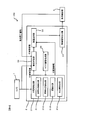
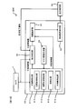
- FIG. 4 is an example of a control block diagram of the in-vehicle device according to the first embodiment of the present invention.
- the control unit 2 functions as an attached matter detection unit 31, a device selection unit 32, a control signal output unit 33, a removal determination unit 34, and a mask image generation unit 35.
- the adhering matter detection unit 31 detects adhering matter from the captured image output by the camera 1.
- the adhering matter detection unit 31 includes a daytime water droplet detection unit 311, a nighttime water droplet detection unit 312, a mud detection unit 313, a water droplet trace detection unit 314, and the like.
- the photographed image output from the camera 1 is input to the daytime water droplet detection unit 311, the nighttime water droplet detection unit 312, the mud detection unit 313, the water droplet trace detection unit 314, and the like of the attached matter detection unit 31.
- the daytime water droplet detection unit 311 and the nighttime water droplet detection unit 312 detect the adhering water droplets from the captured image.
- the daytime water droplet detection unit 311 and the nighttime water droplet detection unit 312 are selectively used according to the brightness of the surroundings of the vehicle. When the surroundings of the vehicle are bright (daytime), the daytime water droplet detection unit 311 is used, and when the surroundings of the vehicle are dark (nighttime), the nighttime water droplet detection unit 312 is used.
- the mud detector 313 detects mud deposits from the captured image.
- the water drop mark detection unit 314 detects a deposit of water drop marks from the captured image. Information such as the position, shape, and size of the deposit detected by each unit of the deposit detection unit 31 is output to the apparatus selection unit 32 and the removal determination unit 34 as deposit information.
- each part of the adhering matter detection unit 31 it is detected that an adhering matter that cannot be removed such as a lens flaw and an adhering matter adhering to the light shielding plate 1 a is detected as an adhering matter of water droplets, mud, or water droplet marks. is there. If the output of compressed air or washer liquid is repeatedly applied to deposits that cannot be removed, mud may be dried by the compressed air, or a washer tank (not shown) may be depleted. In order to suppress the output of compressed air or washer fluid to the deposit that cannot be removed, the deposit detector 31 uses an image of the deposit that cannot be removed as a mask image when detecting the deposit.
- this mask image used by the attached matter detection unit 31 is referred to as a non-change mask.
- the adhering matter detection unit 31 applies predetermined image processing such as edge detection processing to the photographed image, and then applies a non-change mask so that the adhering matter is not detected from the image masked with the non-change mask. To do.
- the non-change mask is generated by the mask image generation unit 35.
- the device selection unit 32 selects, from the air pump 6 and the washer pump 7, an attachment removal unit used for removing (wiping, washing) the attachment detected by the attachment detection unit 31 from the photographing lens.
- the device selection unit 32 outputs information on the selected deposit removal unit to the control signal output unit 33.
- the device selection unit 32 operates based on the number of operations A in which the removal operation using compressed air is performed by operating the air pump 6 and the number of operations B in which the removal operation is performed by operating the washer pump 7. Select the removal part.
- the number of operations A and the number of operations B are stored in the RAM 10 and are shared between the device selection unit 32 and the removal determination unit 34.
- the initialization of the operation count A and the operation count B may be performed when the adhering matter detection unit 31 detects the adhering matter.
- the control signal output unit 33 generates a control signal for requesting the operation of the deposit removal unit selected by the device selection unit 32 and outputs the control signal to the cleaning control unit 5.
- This control signal includes information on the deposit removal unit selected by the device selection unit 32 and control amounts such as cleaning strength and cleaning time.
- the removal determination unit 34 determines whether or not the deposit is removed (wiped, washed) from the photographing lens after the cleaning control unit 5 completes the operation control of the air pump 6 and the washer pump 7. A captured image is input from the camera 1 to the removal determination unit 34 for each frame, and an operation completion signal is input from the cleaning control unit 5.
- the removal determination unit 34 When the operation completion signal is input from the cleaning control unit 5, the removal determination unit 34 generates a difference image between the photographed image before the removal operation and the photographed image after the removal operation, and attaches it based on the difference image. It is determined whether or not the kimono has been removed (wiping, washing). If the deposit is not removed, the removal determining unit 34 increments the number of operations of the deposit removing unit that has performed the removal operation, and the device selecting unit 32 uses the deposit information input from the deposit detecting unit 31. Output to. When the deposit information is output from the removal determination unit 34, the device selection unit 32 selects the deposit removal unit based on the number of operations after the increment, and outputs information on the deposit removal unit as a control signal output unit 33. Output to.
- the mask image generation unit 35 generates or updates a non-change mask.
- the mask image generation unit 35 acquires an image after the removal operation from the removal determination unit 34, and generates a non-change mask based on the image. Update.
- the generated non-change mask is stored in a storage medium such as the RAM 10.
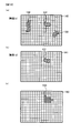
- non-change mask generation will be described using the example shown in FIGS. 12 (a) to 12 (c).
- FIG. 12A it is assumed that it is detected that the deposit 131, the deposit 132, and the deposit 133 are attached to the image 140 at time t1 before the cleaning operation. Thereafter, a cleaning operation is performed, and it is assumed that the deposit 132 and the deposit 133 are removed from the deposits.
- the mask image generation unit 35 generates a non-change mask 150 as shown in FIG. 12C based on the image 141 at time t2.
- the non-change mask 150 holds information on the non-change area 134 in an area corresponding to the remaining deposit 131. Note that the non-change mask 150 may have a resolution lower than that of the image 140 and the image 141. By reducing the resolution, an effect of saving the storage area and an effect of reducing the processing time when using the non-change mask are produced.
- the CPU 12 creates a region that is an attachment region of the image 142 and that is not a non-change region of the non-change mask 150 (referred to as an attachment region after application of the non-change mask). For example, the CPU 12 performs a raster scan from the upper left of the image, and registers each pixel that is included in the attachment region and not included in the non-change region as the attachment region after application of the non-change mask.
- the deposit area after application of the non-change mask represents a newly deposited deposit area.
- FIG. 5 is a flowchart related to the daytime water droplet detection unit 311.
- the CPU 12 performs a well-known edge detection process on the captured image output from the camera 1 to generate an edge image.
- step S ⁇ b> 3111 the CPU 12 extracts pixels whose edge strength is slightly blurred from the edge image generated in step S ⁇ b> 3110.
- the CPU 12 extracts an edge whose edge intensity included in the edge image is a predetermined threshold value Th1 or more and a threshold value Th2 or less. This utilizes the phenomenon that water droplets become weak edges in the edge image when the surroundings of the vehicle are bright, such as in the daytime.
- step S3112 the CPU 12 applies the non-change mask generated by the mask image generation unit 35 to the extraction result of step S3111.
- step S ⁇ b> 3113 the CPU 12 outputs the extraction result of step S ⁇ b> 3111 to which the non-change mask is applied as a water droplet deposit.
- FIG. 6 is a flowchart relating to the nighttime water droplet detection unit 312.
- the night water droplet detection unit 312 uses a phenomenon that appears in a captured image as a light spot by reflecting or refracting light from a headlight or the like of a rear vehicle to a water droplet attached to a photographing lens when the periphery of the vehicle is dark such as at night.
- the CPU 12 extracts the light spot from the captured image output by the camera 1.
- the CPU 12 applies the non-change mask generated by the mask image generation unit 35 to the extraction result of step S3120.
- the CPU 12 outputs the extraction result of step S 3120 to which the non-change mask is applied as a water droplet deposit.
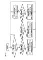
- FIG. 7 is a flowchart regarding the removal determination unit 34.
- step S ⁇ b> 340 the CPU 12 determines whether or not the deposit information is input from the deposit detection unit 31. The CPU 12 repeats the process of step S340 until the deposit information is input, and when the deposit information is input, the process proceeds to step S341.
- step S341 the CPU 12 determines whether or not an operation completion signal is input from the cleaning control unit 5. The CPU 12 repeats the process of step S341 until the operation completion signal is input, and when the operation completion signal is input, the process proceeds to step S342.
- step S342 the CPU 12 increments the number of operations (the number of operations A or the number of operations B) of the deposit removal unit (the deposit removal unit that has completed the removal operation) selected by the device selection unit 32.
- step S343 the CPU 12 acquires the latest photographed image after the removal operation from the camera 1 and stores it in the RAM 10.
- step S344 the CPU 12 generates a difference image between the photographed image after the removal operation acquired in step S343 and the photographed image before the removal operation.
- step S345 the CPU 12 determines whether there is an image of the deposit that has not been removed from the difference image generated in step S344. If the determination in step S345 is affirmative, that is, if the deposit that has not been removed is present in the difference image, the CPU 12 advances the process to step S346. On the other hand, if a negative determination is made in step S345, the process proceeds to step S340.
- step S346 the CPU 12 determines the type of the removed deposit. For each deposit, the CPU 12 changes the brightness of the pixel block representing the deposit before and after wiping, the size or shape of the deposit, the number of operations A, the number of operations B, the type of the deposit removal unit operated immediately before, etc. Based on the above, the type of the deposit is determined. For example, the deposit removed by one or more removal operations of the air pump 6 or having changed shape is determined to be a water droplet. On the other hand, even if the removal operation of the air pump 6 is performed three times, it is determined that the deposit that has not been removed by one or more operations of the washer pump 7 or whose shape has changed is mud. The CPU 12 may output information on the type of the deposit to the cleaning control unit 5 as a control signal control amount.
- step S347 the CPU 12 outputs the deposit information input in step S340 to the device selection unit 32. Thereafter, the CPU 12 advances the process to step S341.
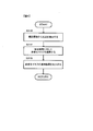
- FIG. 8 is a flowchart regarding the device selection unit 32.
- the flowchart illustrated in FIG. 8 is a flowchart when the apparatus selection unit 32 preferentially selects the air pump 6.
- step S321 the CPU 12 determines whether or not the deposit information is input from the deposit detection unit 31 or the removal determination unit 34 in step S347 of FIG.
- the time when the attached matter information is input from the attached matter detecting unit 31 means that the attached matter is detected by the attached matter detecting unit 31. Further, when the attached matter information is input from the removal determining unit 34, that is, when the removal determining unit 34 determines that there is an attached matter that has not been removed from the difference image in step S345, in other words, the attached matter is removed. This is the time when the removal determining unit 34 determines that it has not been performed.
- the CPU 12 repeats the process of step S321 until the deposit information is input to the device selection unit 32. When the deposit information is input to the device selection unit 32, the CPU 12 advances the process to step S322.
- CPU12 advances a process to step S323 when step S322 is affirmed and advances a process to step S324, when step S322 is negatively determined.
- step S323 the CPU 12 selects the air pump 6 as the deposit removal unit, and causes the control signal output unit 33 to output a control signal requesting the operation of the air pump 6 to the cleaning control unit 5.
- the CPU 12 advances the process to Step S321.
- the cleaning control unit 5 to which the control signal is input from the control signal output unit 33 outputs an operation completion signal to the removal determination unit 34 after the removal operation by the air pump 6.
- CPU12 advances a process to step S325, when step S324 is affirmed and advances a process to step S326, when step S324 is negatively determined.
- step S325 the CPU 12 selects the washer pump 7 as the deposit removal unit, and causes the control signal output unit 33 to output a control signal requesting the operation of the washer pump 7.
- step S325 the CPU 12 advances the process to step S321.
- the cleaning control unit 5 to which the control signal is input from the control signal output unit 33 outputs an operation completion signal to the removal determination unit 34 after the removal operation by the washer pump 7.
- step S326 the mask image generation unit 35 is caused to generate a non-change mask.
- the CPU 12 advances the process to step S321.
- the in-vehicle device 100 includes a control unit 2.
- the control unit 2 outputs a control signal to the cleaning control unit 5 that controls the air pump 6 and the washer pump 7 for removing the deposits attached to the photographing lens of the camera 1.
- the control unit 2 selects an adhering matter detection unit 31 that detects adhering matter adhering to the photographic lens from the photographed image output from the camera 1, and one or more adhering matter removing units from among the plural adhering matter removing units.
- An apparatus selection unit 32 ; a removal determination unit 34 that determines whether or not the deposit is removed from the photographing lens by the removal operation by the one or more deposit removal unit selected by the device selection unit 32 using the captured image; A control signal output unit 33 that outputs a control signal including at least information on the one or more deposit removal units selected by the apparatus selection unit 32 toward the cleaning control unit 5.
- the apparatus selection unit 32 receives the deposit information from the deposit detection unit 31 or the removal determination unit 34 in step S321, that is, when the deposit detection unit 31 detects the deposit adhering to the photographing lens, or When the removal determining unit 34 determines that the attached matter has not been removed from the photographing lens, one or more attachments are made based on the number of operations A and B of the removal operation performed using each of the plurality of attached matter removing units. Select the kimono removal unit.
- the control part 2 by the 1st Embodiment of this invention can wash
- the removal determining unit 34 determines that the attached matter is not removed from the photographing lens. Then, a mask image generation unit 35 that generates an image of the deposit that has not been removed as a non-change mask and stores it in the RAM 10 is further provided.
- the attached matter detection unit 31 does not detect the attached matter stored in the RAM 10 as a non-change mask.
- the adhering matter detection unit 31 it is possible to prevent the adhering matter detection unit 31 from repeatedly detecting an object that cannot be removed by the adhering matter removing unit, such as a lens scratch or an adhering matter adhering to the light shielding plate 1a, and continuing the wasteful cleaning action.
- Device selection unit 32 of the control unit 2 when the number of operations A removal operation of the air pump 6 is equal to or less than a predetermined number A L (step S322 YES in FIG. 8), select the air pump 6 (step S323). Number of operations A removal operation by the air pump 6 is greater than the predetermined number of times A L (step S322 NO), when the operation number B of removing operation by washer pump 7 is lower than a predetermined value B L (step S324 YES), washer pump 7 Is selected (step S325).
- the wipeping device 14 shows whether or not wiping is possible according to the type of wiping device (air, washer, and wiper) with respect to the type of deposit (water droplets / mud / water droplet marks / lens scratches).
- the type of wiping device air, washer, and wiper
- the type of deposit water droplets / mud / water droplet marks / lens scratches.
- FIG. 9 is a block diagram of the in-vehicle device according to the second embodiment.
- the in-vehicle device 200 is different from the in-vehicle device 100 according to the first embodiment in that the in-vehicle device 200 includes a wiper 14 for wiping the photographing lens of the camera 1 and a wiper driving unit 13 for driving the wiper 14.
- the cleaning control unit 55 corresponding to the cleaning control unit 5 according to the first embodiment further controls the operation of the wiper driving unit 13 in addition to the air pump 6 and the washer pump 7.
- the wiper 14 can remove the deposits of water droplets that are difficult to remove even with a washer liquid from the photographing lens by wiping.
- the cleaning control unit 55 outputs an operation completion signal to the removal determination unit 34 even when the removal operation by the wiper driving unit 13 is completed.
- FIG. 10 is a control block diagram of the in-vehicle device according to the second embodiment.
- the control unit block diagram of FIG. 10 is different from the control block diagram of FIG. 4 in that the control unit 2, the cleaning control unit 5, and the device selection unit 32 are changed to the control unit 52, the cleaning control unit 55, and the device selection unit 36, respectively.
- the same reference numerals are given to the same processes as those in the control block diagram of FIG. 4, and the description thereof is omitted below.
- the device selection unit 36 determines whether the air pump 6, the washer pump 7, the wiper drive unit 13, or the like based on the operation number A of the air pump 6, the operation number B of the washer pump 7, and the operation number C of the wiper drive unit 13. The deposit removing part is selected from the list.
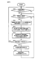
- FIG. 11 is a flowchart regarding the device selection unit 36 executed by the control unit 52.
- the processing in FIG. 11 includes processing related to the wiper driving unit 13, step S366 and step S367.
- step S361 in FIG. 11 the CPU 12 performs the same process as in step S321 in FIG.
- step S362 in FIG. 11 the CPU 12 performs the same determination as in step S322 in FIG.
- step S363 in FIG. 11 the CPU 12 performs the same determination as in step S323 in FIG.
- step S364 in FIG. 11 the CPU 12 performs the same determination as in step S324 in FIG. 8 except that the process proceeds to step S366 in which a determination regarding the wiper driving unit 13 is made when a negative determination is made. If the determination at step S364 is affirmative, the CPU 12 advances the process to step S365 in the same manner as step S324 in FIG. In step S365 in FIG. 11, the CPU 12 performs the same process as in step S325 in FIG.
- the CPU 12 advances the process to step S367 when the determination in step S366 is affirmative, and advances the process to step S368 when the determination in step S366 is negative.
- the CPU 12 selects the wiper driving unit 13 as the deposit removing unit, and causes the control signal output unit 33 to output a control signal requesting the operation of the wiper driving unit 13 to the cleaning control unit 55. After completing the process in Step S367, the CPU 12 advances the process to Step S361.
- the cleaning control unit 5 to which the control signal is input from the control signal output unit 33 outputs an operation completion signal to the removal determination unit 34 after the removal operation by the wiper driving unit 13.
- the removal determination unit 34 determines that in step S345. It is determined that the deposit is a water drop mark or the like.
- step S368 in FIG. 11 processing similar to that in step S326 in FIG. 8 is performed.
- the removal determination part 34 determines the classification of the removed deposit
- the CPU 12 is operated immediately before the wiping, the luminance change of the pixel block representing the deposit before and after the wiping, the size or shape of the deposit, the operation count A, the operation count B, and the operation count C.
- the type of the deposit is determined based on the type of the deposit removal unit. For example, the removal operation of the air pump 6 is performed three times, and the removal operation of the washer pump 7 is not performed even if the removal operation is performed once or more. It is determined that the adhered matter is a water drop mark.
- the in-vehicle device 200 includes a control unit 52.
- the control unit 52 outputs a control signal to the cleaning control unit 55 that controls the air pump 6, the washer pump 7, and the wiper driving unit 13 for removing the deposits attached to the photographing lens of the camera 1.
- the control unit 52 selects an adhering matter detection unit 31 that detects adhering matter adhering to the photographing lens from the photographed image output from the camera 1, and one or more adhering matter removing units from among the plural adhering matter removing units.
- a device selection unit 36, and a removal determination unit 34 that determines whether or not the deposit is removed from the photographing lens by the removal operation by the one or more deposit removal unit selected by the device selection unit 36 using the photographed image.
- a control signal output unit 33 that outputs a control signal including at least information on the one or more deposit removing units selected by the device selection unit 36 to the cleaning control unit 5.
- the apparatus selection unit 36 receives the deposit information from the deposit detection unit 31 or the removal determination unit 34 in step S361, that is, when the deposit detection unit 31 detects the deposit adhering to the photographing lens, or Based on the number of operation times A, B, and C of the removal operation performed using each of the plurality of attached matter removing units when the removed determining unit 34 determines that the attached matter is not removed from the photographing lens.
- the above deposit removal unit is selected.
- the control part 2 by the 2nd Embodiment of this invention can wash
- Device selection unit 36 of the control unit 2 when the number of operations A removal operation of the air pump 6 is equal to or less than a predetermined number A L (step S362 YES in FIG. 8), select the air pump 6 (step S363). Number of operations A removal operation by the air pump 6 is greater than the predetermined number of times A L (step S362 NO), when the operation number B of removing operation by washer pump 7 is lower than a predetermined value B L (step S364 YES), washer pump 7 Is selected (step S365).
- Each of the LDW, PED, RSR, and IMD image recognition functions executed in the third embodiment is a function that operates while the vehicle is traveling, and detects an adhering substance when the vehicle speed exceeds a certain vehicle speed (for example, 5 km / h). 31 is operated. Whether the vehicle speed is equal to or higher than a certain vehicle speed is determined using a vehicle speed sensor (not shown).
- the mud detection unit 313 captures images at two different times using the camera 1, generates a difference image from these images, and determines the shape of the difference region in the difference image. Thus, it is possible to determine whether mud adheres.
- the difference image generation method will be described with reference to FIG.
- the difference image is generated by calculating a difference between the latest photographed image and the reference image.
- the reference image is generated based on past captured images that are continuously output in time series from the camera 1 before the latest captured image.
- FIG. 15 an arrow indicating a time change is illustrated, and time t 0 to t 5 is illustrated on the arrow according to the frame rate of the camera 1. Under the arrows representing the time variation, the captured image P 0 ⁇ P 5 which is output from the camera 1, respectively at time t 0 ⁇ t 5 are illustrated.
- the captured images P 0 to P 5 are stored in the RAM 10 every time they are output from the camera 1.
- the accumulation of the captured image to RAM10 shall be started in time t 0. That is, the oldest captured image in the captured image captured image P 0 is stored in the RAM10 in FIG. 6, the captured image P 5 is at the latest captured image.
- the reference image Q i is the same as the captured image P i-1 (for example, the captured image P 4 ) stored immediately before in the RAM 10 when the newly captured image P i is output from the camera 1 (for example, time t 5 ).
- the reference image Q i-1 at the time when the captured image P i is output it is generated by the following equations [1] and [2].
- Q i k ⁇ P i ⁇ 1 + (1 ⁇ k) ⁇ Q i ⁇ 1 (when i ⁇ 2)
- the mud detection unit 313 includes a latest captured image (for example, the captured image P 5 ) output from the camera 1 and a reference image (for example, the reference image Q 5 ) at the time when the latest captured image is output. A difference image is generated.
- the shape of the difference area is determined, for example, whether the area is within a predetermined range or whether the aspect ratio of the difference area is within a predetermined range. Is attached, and the attachment position and the number of attachments are output.
- the apparatus selection units 32 and 36 may select a plurality of deposit removal units. For example, the selection may be made such that compressed air is output after the washer fluid is output in step S325. Further, the number of operations A removal operation by the air pump 6 is greater than the predetermined number of times A L, when the number of operations B removal operation by washer pump 7 is lower than a predetermined value B L, to output the the washer fluid and compressed air simultaneously It may be. Further, the plurality of deposit removing parts are not limited to the air pump 6, the washer pump 7, and the wiper driving unit 13, and a deposit removing unit that can be selected by the device selecting units 32 and 36 is newly added.
- any one of the air pump 6, the washer pump 7, and the wiper driving unit 13 may be replaced with a new deposit removing unit.
- the air pump 6 may function as the washer pump 7.
- the camera 1 may not include the light shielding plate 1a.
- (Modification 3) The daytime water droplet detection unit 311, the nighttime water droplet detection unit 312, the mud detection unit 313, the water droplet trace detection unit 314, etc., illustrated in FIG. Some detection units may not be provided, or a lens flaw detection unit that detects lens flaws may be further provided.
- the third embodiment may be implemented in combination with the first embodiment or the second embodiment.
- the adhering matter detection 31 may operate when the vehicle speed is equal to or higher than a certain vehicle speed, as in the third embodiment.
Landscapes
- Engineering & Computer Science (AREA)
- Mechanical Engineering (AREA)
- Automation & Control Theory (AREA)
- Multimedia (AREA)
- Signal Processing (AREA)
- Water Supply & Treatment (AREA)
- Studio Devices (AREA)
- Devices For Checking Fares Or Tickets At Control Points (AREA)
- Camera Bodies And Camera Details Or Accessories (AREA)
- Cameras In General (AREA)
Abstract
Description
本発明の第2の態様によると、第1の態様の車載装置において、複数の方法の付着物除去部の各々を用いた除去動作が複数の方法の付着物除去部の各々に対応した複数の所定回数行われた後に、撮影レンズから付着物が除去されていないと除去判定部が判定したとき、その除去されていない付着物の画像をマスク画像として記憶するマスク画像記憶部をさらに備え、付着物検出部は、マスク画像記憶部にマスク画像として記憶されている付着物については、検出の対象としないことが好ましい。
本発明の第3の態様によると、第2の態様の車載装置において、第1の方法の付着物除去部は、圧縮空気を用いて付着物を払拭し、第2の方法の付着物除去部は、ウォッシャー液を用いて付着物を払拭し、選択部は、第1の方法の付着物除去部の除去動作の回数が第1の所定回数以下のとき、第1の方法の付着物除去部を選択し、第1の方法の付着物除去部の除去動作の回数が第1の所定回数より大きく、第2の方法の付着物除去部の除去動作の回数が第2の所定回数以下のとき、第2の方法の付着物除去部を選択し、第1の方法の付着物除去部の回数が第1の所定回数より大きく、第2の方法の付着物除去部の回数が第2の所定回数より大きいとき、マスク画像記憶部にマスク画像を記憶させることが好ましい。
本発明の第4の態様によると、第3の態様の車載装置において、複数の方法の付着物除去部は、ワイパを用いて付着物を払拭する第3の方法の付着物除去部をさらに含み、選択部は、第1の方法の付着物除去部の除去動作の回数が第1の所定回数以下のとき、第1の方法の付着物除去部を選択し、第1の方法の付着物除去部の除去動作の回数が第1の所定回数より大きく、第2の方法の付着物除去部の除去動作の回数が第2の所定回数以下のとき、第2の方法の付着物除去部を選択し、第1の方法の付着物除去部の回数が第1の所定回数より大きく、第2の方法の付着物除去部の回数が第2の所定回数より大きく、第3の方法の付着物除去部の除去動作の回数が第3の所定回数以下のとき、第3の方法の付着物除去部を選択し、第1の方法の付着物除去部の回数が第1の所定回数より大きく、第2の方法の付着物除去部の回数が第2の所定回数より大きく、第3の方法の付着物除去部の回数が第3の所定回数より大きいとき、マスク画像記憶部にマスク画像を記憶させることが好ましい。
本発明の第5の態様によると、第3の態様の車載装置において、除去判定部は、選択部により選択された第1の方法の付着物除去部による除去動作により除去された付着物の種別をさらに判別し、第1の方法の付着物除去部の除去動作により除去された付着物を水滴の付着物と判別して、第2の方法の付着物除去部の除去動作により除去された付着物を泥の付着物と判別することが好ましい。
本発明の第6の態様によると、第4の態様の車載装置において、除去判定部は、選択部により選択された第1の方法の付着物除去部による除去動作により除去された付着物の種別をさらに判別し、第1の方法の付着物除去部の除去動作により除去された付着物を水滴の付着物と判別して、第2の方法の付着物除去部の除去動作により除去された付着物を泥の付着物と判別して、第3の方法の付着物除去部の除去動作により除去された付着物を水滴痕の付着物として判別することが好ましい。
図1は、本発明の一実施形態による車載装置100のブロック構成図である。図1に示す車載装置100は、車両に搭載されて使用されるものであり、遮光板1aが取り付けられたカメラ1と、制御部2と、警報出力部3と、動作状態報知部4と、洗浄制御部5と、エアーポンプ6と、ウォッシャーポンプ7と、エアーノズル8と、ウォッシャーノズル9とを備える。
車載装置100は制御部2を備える。制御部2は、カメラ1の撮影レンズに付着した付着物を除去するためのエアーポンプ6とウォッシャーポンプ7とを制御する洗浄制御部5に向けて制御信号を出力する。制御部2は、カメラ1から出力された撮影画像から撮影レンズに付着した付着物を検出する付着物検出部31と、複数の付着物除去部の中から1以上の付着物除去部を選択する装置選択部32と、撮影画像を用いて装置選択部32により選択された1以上の付着物除去部による除去動作により撮影レンズから付着物が除去されたか否かを判定する除去判定部34と、装置選択部32が選択した1以上の付着物除去部に関する情報を少なくとも含む制御信号を洗浄制御部5に向けて出力する制御信号出力部33と、を備える。装置選択部32は、ステップS321において付着物検出部31または除去判定部34から付着物情報を入力されたとき、すなわち付着物検出部31が撮影レンズに付着した付着物を検出したとき、または、撮影レンズから付着物が除去されていないと除去判定部34が判定したときに、複数の付着物除去部の各々を用いて行った除去動作の動作回数AおよびBに基づいて、1以上の付着物除去部を選択する。本発明の第1の実施形態による制御部2は、このような構成を有することにより車載用カメラの撮影レンズを好適に洗浄することができる。
図9は、第2の実施の形態による車載装置のブロック構成図である。車載装置200は、第1の実施の形態による車載装置100と比べて、カメラ1の撮影レンズを払拭するワイパ14と、ワイパ14を駆動するワイパ駆動部13とを備える点が異なる。第1の実施の形態による洗浄制御部5に相当する洗浄制御部55は、エアーポンプ6およびウォッシャーポンプ7のほかにワイパ駆動部13の動作をさらに制御する。ワイパ14は、ウォッシャー液でも除去が困難な水滴痕の付着物を、払拭により比較的容易に撮影レンズから除去することができる。洗浄制御部55は、ワイパ駆動部13による除去動作が完了したときも、動作完了信号を除去判定部34へ出力する。
車載装置200は制御部52を備える。制御部52は、カメラ1の撮影レンズに付着した付着物を除去するためのエアーポンプ6とウォッシャーポンプ7とワイパ駆動部13とを制御する洗浄制御部55に向けて制御信号を出力する。制御部52は、カメラ1から出力された撮影画像から撮影レンズに付着した付着物を検出する付着物検出部31と、複数の付着物除去部の中から1以上の付着物除去部を選択する装置選択部36と、撮影画像を用いて、装置選択部36により選択された1以上の付着物除去部による除去動作により撮影レンズから付着物が除去されたか否かを判定する除去判定部34と、装置選択部36が選択した1以上の付着物除去部に関する情報を少なくとも含む制御信号を洗浄制御部5に向けて出力する制御信号出力部33と、を備える。装置選択部36は、ステップS361において付着物検出部31または除去判定部34から付着物情報を入力されたとき、すなわち付着物検出部31が撮影レンズに付着した付着物を検出したとき、または、撮影レンズから付着物が除去されていないと除去判定部34が判定したときに、複数の付着物除去部の各々を用いて行った除去動作の動作回数A、B、およびCに基づいて、1以上の付着物除去部を選択する。本発明の第2の実施形態による制御部2は、このような構成を有することにより車載用カメラの撮影レンズを好適に洗浄することができる。
次に、第3の実施の形態による車載装置を説明する。本実施形態は、第1の実施の形態による車載装置とほぼ同様であるが、車両が移動しているときに付着物検出31を動作させることを特徴とする。
Qi=Pi-1 (i=1のとき)・・・〔1〕
Qi=k×Pi-1+(1-k)×Qi-1 (i≧2のとき)・・・〔2〕
ここで、kは0<k≦1の係数であって、たとえばk=0.1。
(変形例1)装置選択部32および36は、複数の付着物除去部を選択することにしてもよい。たとえば、ステップS325においてウォッシャー液を出力してから圧縮空気を出力するような選択を行ってもよい。また、エアーポンプ6による除去動作の動作回数Aが所定回数ALより大きく、ウォッシャーポンプ7による除去動作の動作回数Bが所定値BL以下のとき、ウォッシャー液と圧縮空気とを同時に出力することにしてもよい。また、複数の付着物除去部は、エアーポンプ6、ウォッシャーポンプ7、ワイパ駆動部13だけに限定されず、装置選択部32および36が選択可能な付着物除去部を新たに追加することにしてもよく、エアーポンプ6、ウォッシャーポンプ7、ワイパ駆動部13のいずれかを新たな付着物除去部と入れ替えることにしてもよい。また、エアーポンプ6がウォッシャーポンプ7として機能するように構成してもよい。
(変形例2)カメラ1は、遮光板1aを備えなくてもよい。
(変形例3)図4および図10において付着物検出部31に図示された昼間水滴検出部311、夜間水滴検出部312、泥検出部313、水滴痕検出部314などは、あくまで例示であり、一部の検出部を備えていなくてもよいし、レンズ傷を検出するレンズ傷検出部をさらに備えていてもよい。
日本国特許出願2012年第149868号(2012年7月3日出願)
2:制御部、5:洗浄制御部、32:装置選択部、100:車載装置
13:ワイパ駆動部、52:制御部、55:洗浄制御部、36:装置選択部、200:車載装置
Claims (6)
- 車載用カメラの撮影レンズに付着した付着物を除去する複数の方法の付着物除去部を制御する洗浄制御部に向けて制御信号を出力する車載装置であって、
入力された車速が予め定められた車速以上である場合、前記車載用カメラから出力された撮影画像から前記撮影レンズに付着した付着物を検出する付着物検出部と、
前記複数の方法の付着物除去部の中から第1の方法の付着物除去部を選択する選択部と、
前記撮影画像を用いて、前記選択部により選択された前記第1の方法の付着物除去部による除去動作により前記撮影レンズから付着物が除去されたか否かを判定する除去判定部と、
を備え、
前記選択部は、前記撮影レンズから付着物が除去されていないと前記除去判定部が判定したときに、前記第1の方法の付着物除去部を用いて行った除去動作の回数に基づいて、前記第1の方法の付着物除去部とは異なる第2の方法の付着物除去部を選択する車載装置。 - 請求項1に記載の車載装置において、
前記複数の方法の付着物除去部の各々を用いた除去動作が前記複数の方法の付着物除去部の各々に対応した複数の所定回数行われた後に、前記撮影レンズから付着物が除去されていないと前記除去判定部が判定したとき、その除去されていない付着物の画像をマスク画像として記憶するマスク画像記憶部をさらに備え、
前記付着物検出部は、前記マスク画像記憶部に前記マスク画像として記憶されている付着物については、検出の対象としない車載装置。 - 請求項2に記載の車載装置において、
前記第1の方法の付着物除去部は、圧縮空気を用いて前記付着物を払拭し、
前記第2の方法の付着物除去部は、ウォッシャー液を用いて前記付着物を払拭し、
前記選択部は、
前記第1の方法の付着物除去部の除去動作の回数が第1の所定回数以下のとき、前記第1の方法の付着物除去部を選択し、
前記第1の方法の付着物除去部の除去動作の回数が前記第1の所定回数より大きく、前記第2の方法の付着物除去部の除去動作の回数が第2の所定回数以下のとき、前記第2の方法の付着物除去部を選択し、
前記第1の方法の付着物除去部の回数が前記第1の所定回数より大きく、前記第2の方法の付着物除去部の回数が前記第2の所定回数より大きいとき、前記マスク画像記憶部に前記マスク画像を記憶させる車載装置。 - 請求項3に記載の車載装置において、
前記複数の方法の付着物除去部は、ワイパを用いて前記付着物を払拭する第3の方法の付着物除去部をさらに含み、
前記選択部は、
前記第1の方法の付着物除去部の除去動作の回数が第1の所定回数以下のとき、前記第1の方法の付着物除去部を選択し、
前記第1の方法の付着物除去部の除去動作の回数が前記第1の所定回数より大きく、前記第2の方法の付着物除去部の除去動作の回数が第2の所定回数以下のとき、前記第2の方法の付着物除去部を選択し、
前記第1の方法の付着物除去部の回数が前記第1の所定回数より大きく、前記第2の方法の付着物除去部の回数が前記第2の所定回数より大きく、前記第3の方法の付着物除去部の除去動作の回数が第3の所定回数以下のとき、前記第3の方法の付着物除去部を選択し、
前記第1の方法の付着物除去部の回数が前記第1の所定回数より大きく、前記第2の方法の付着物除去部の回数が前記第2の所定回数より大きく、前記第3の方法の付着物除去部の回数が前記第3の所定回数より大きいとき、前記マスク画像記憶部に前記マスク画像を記憶させる車載装置。 - 請求項3に記載の車載装置において、
前記除去判定部は、前記選択部により選択された前記第1の方法の付着物除去部による除去動作により除去された付着物の種別をさらに判別し、
前記第1の方法の付着物除去部の除去動作により除去された付着物を水滴の付着物と判別して、
前記第2の方法の付着物除去部の除去動作により除去された付着物を泥の付着物と判別する車載装置。 - 請求項4に記載の車載装置において、
前記除去判定部は、前記選択部により選択された前記第1の方法の付着物除去部による除去動作により除去された付着物の種別をさらに判別し、
前記第1の方法の付着物除去部の除去動作により除去された付着物を水滴の付着物と判別して、
前記第2の方法の付着物除去部の除去動作により除去された付着物を泥の付着物と判別して、
前記第3の方法の付着物除去部の除去動作により除去された付着物を水滴痕の付着物として判別する車載装置。
Priority Applications (8)
| Application Number | Priority Date | Filing Date | Title |
|---|---|---|---|
| MX2014015628A MX343202B (es) | 2012-07-03 | 2013-07-03 | Dispositivo a bordo. |
| RU2015103143A RU2640683C2 (ru) | 2012-07-03 | 2013-07-03 | Бортовое устройство |
| US14/409,689 US9956941B2 (en) | 2012-07-03 | 2013-07-03 | On-board device controlling accumulation removing units |
| BR112015000050-9A BR112015000050B1 (pt) | 2012-07-03 | 2013-07-03 | Unidade de controle de um dispositivo montado em um veículo |
| JP2014523768A JP6251169B2 (ja) | 2012-07-03 | 2013-07-03 | 車載装置、制御装置 |
| MYPI2014703935A MY183226A (en) | 2012-07-03 | 2013-07-03 | On-board device controlling accumulation removing units |
| CN201380035355.8A CN104412573B (zh) | 2012-07-03 | 2013-07-03 | 车载装置 |
| EP13813697.3A EP2871831B1 (en) | 2012-07-03 | 2013-07-03 | Control unit of a vehicle-mounted device |
Applications Claiming Priority (2)
| Application Number | Priority Date | Filing Date | Title |
|---|---|---|---|
| JP2012149868 | 2012-07-03 | ||
| JP2012-149868 | 2012-07-03 |
Publications (1)
| Publication Number | Publication Date |
|---|---|
| WO2014007294A1 true WO2014007294A1 (ja) | 2014-01-09 |
Family
ID=49882046
Family Applications (1)
| Application Number | Title | Priority Date | Filing Date |
|---|---|---|---|
| PCT/JP2013/068274 Ceased WO2014007294A1 (ja) | 2012-07-03 | 2013-07-03 | 車載装置 |
Country Status (9)
| Country | Link |
|---|---|
| US (1) | US9956941B2 (ja) |
| EP (1) | EP2871831B1 (ja) |
| JP (1) | JP6251169B2 (ja) |
| CN (1) | CN104412573B (ja) |
| BR (1) | BR112015000050B1 (ja) |
| MX (1) | MX343202B (ja) |
| MY (1) | MY183226A (ja) |
| RU (1) | RU2640683C2 (ja) |
| WO (1) | WO2014007294A1 (ja) |
Cited By (10)
| Publication number | Priority date | Publication date | Assignee | Title |
|---|---|---|---|---|
| EP3069942A1 (en) * | 2015-03-16 | 2016-09-21 | Thunder Power Hong Kong Ltd. | Vehicle camera cleaning system |
| WO2018029925A1 (ja) * | 2016-08-09 | 2018-02-15 | クラリオン株式会社 | 車載装置 |
| JP2018116159A (ja) * | 2017-01-18 | 2018-07-26 | 株式会社デンソーテン | 異物除去制御装置、異物除去制御方法、及び、異物除去制御プログラム |
| WO2018150661A1 (ja) * | 2017-02-14 | 2018-08-23 | クラリオン株式会社 | 車載用撮像装置 |
| JP2019156261A (ja) * | 2018-03-15 | 2019-09-19 | 株式会社小糸製作所 | 車両システム |
| WO2019187241A1 (ja) * | 2018-03-28 | 2019-10-03 | 株式会社デンソー | 車載センサ洗浄装置 |
| JP2019184946A (ja) * | 2018-04-16 | 2019-10-24 | 株式会社デンソーテン | 付着物除去システム、及び付着物の除去方法 |
| JP2021504233A (ja) * | 2017-11-30 | 2021-02-15 | ロベルト・ボッシュ・ゲゼルシャフト・ミト・ベシュレンクテル・ハフツングRobert Bosch Gmbh | 周辺環境捕捉のために形成された装置およびそのような装置のカバーのクリーニング方法 |
| JP2021511244A (ja) * | 2018-01-16 | 2021-05-06 | コノート、エレクトロニクス、リミテッドConnaught Electronics Ltd. | 自動車両用の光学センサの透明な前部要素を洗浄するための洗浄装置、アセンブリ、ならびに方法 |
| JP2022027452A (ja) * | 2020-07-31 | 2022-02-10 | マテックス株式会社 | 車両塗装面の被害診断判定システム |
Families Citing this family (25)
| Publication number | Priority date | Publication date | Assignee | Title |
|---|---|---|---|---|
| US10350647B2 (en) | 2011-03-10 | 2019-07-16 | Dlhbowles, Inc. | Integrated automotive system, nozzle assembly and remote control method for cleaning an image sensor's exterior or objective lens surface |
| US10432827B2 (en) | 2011-03-10 | 2019-10-01 | Dlhbowles, Inc. | Integrated automotive system, nozzle assembly and remote control method for cleaning an image sensors exterior or objective lens surface |
| WO2015157744A1 (en) | 2014-04-11 | 2015-10-15 | Bowles Fluidics Corporation | Integrated automotive system, compact, low-profile nozzle assembly and compact fluidic circuit for cleaning a wide-angle image sensor's exterior surface |
| US10525937B2 (en) | 2014-04-16 | 2020-01-07 | Dlhbowles, Inc. | Integrated multi image sensor and lens washing nozzle assembly and method for simultaneously cleaning a plurality of image sensors |
| JP6835548B2 (ja) * | 2016-11-22 | 2021-02-24 | 株式会社デンソーテン | 付着物除去装置 |
| US10518754B2 (en) | 2017-04-07 | 2019-12-31 | Uatc, Llc | Autonomous vehicle sensor cleaning system |
| US20180354469A1 (en) * | 2017-06-08 | 2018-12-13 | Ford Global Technologies, Llc | Cleaning vehicle sensors |
| US10589724B2 (en) * | 2017-07-12 | 2020-03-17 | Ford Global Technologies, Llc | Stowable vehicle sensor |
| CN107554485B (zh) * | 2017-07-18 | 2019-05-31 | 上海禹点电子科技有限公司 | 挡风玻璃遮挡区域擦拭控制系统及方法 |
| EP3659876B1 (en) * | 2017-07-24 | 2023-12-20 | Koito Manufacturing Co., Ltd. | Vehicle cleaner system |
| JP6772113B2 (ja) * | 2017-08-02 | 2020-10-21 | クラリオン株式会社 | 付着物検出装置、および、それを備えた車両システム |
| JP7055619B2 (ja) * | 2017-11-14 | 2022-04-18 | 株式会社デンソーテン | 気体噴出装置および気体噴出方法 |
| CN111867895B (zh) * | 2018-03-07 | 2024-03-08 | 株式会社小糸制作所 | 车辆用清洁系统、车辆系统、基于车辆用清洁系统的清洗方法、车辆用清洁器控制装置 |
| JP2020022010A (ja) * | 2018-07-30 | 2020-02-06 | キヤノン株式会社 | 清掃装置及び清掃方法 |
| JP7103185B2 (ja) * | 2018-11-20 | 2022-07-20 | トヨタ自動車株式会社 | 判定装置、車両制御装置、判定方法、判定プログラム |
| CN119048462A (zh) * | 2019-01-30 | 2024-11-29 | 杭州海康威视数字技术股份有限公司 | 一种车载相机镜头的污染处理方法及系统 |
| CN111845647B (zh) * | 2019-04-28 | 2021-07-27 | 上海汽车集团股份有限公司 | 一种汽车摄像头清洁系统及方法 |
| CN110203137A (zh) * | 2019-05-10 | 2019-09-06 | 上海海事大学 | 一种汽车倒车影像仪防雨护套装置 |
| US11241721B2 (en) * | 2019-10-15 | 2022-02-08 | Toyota Motor Engineering & Manufacturing North America, Inc. | Sensor cleaning system and sensor cleaning method for vehicle |
| CN111246167A (zh) * | 2020-01-13 | 2020-06-05 | 惠龙易通国际物流股份有限公司 | 电子监控区域设置方法及装置 |
| CN111169431A (zh) * | 2020-01-16 | 2020-05-19 | 海拉(厦门)电气有限公司 | 车载传感器或摄像头的清洗系统及清洗方法 |
| US11623585B2 (en) | 2020-04-30 | 2023-04-11 | Zoox, Inc. | Sensor pod coverage and placement on vehicle |
| US11760313B2 (en) * | 2020-04-30 | 2023-09-19 | Zoox, Inc. | Sensor pod cleaning system |
| US11953623B2 (en) | 2020-04-30 | 2024-04-09 | Zoox, Inc. | Sensor pod assembly |
| CA3219769A1 (en) | 2021-07-06 | 2023-01-12 | Dlhbowles, Inc. | Pulsating spray cleaning nozzle assembly and method |
Citations (4)
| Publication number | Priority date | Publication date | Assignee | Title |
|---|---|---|---|---|
| JP2001171491A (ja) * | 1999-12-16 | 2001-06-26 | Matsushita Electric Ind Co Ltd | 車載カメラ装置及び車載カメラの洗浄方法 |
| JP2009220719A (ja) * | 2008-03-17 | 2009-10-01 | Toyota Motor Corp | 車載カメラ雨滴除去装置 |
| JP2010109516A (ja) | 2008-10-29 | 2010-05-13 | Nikon Corp | 撮像装置 |
| JP2011240916A (ja) * | 2009-09-29 | 2011-12-01 | Denso Corp | 車両用操作装置 |
Family Cites Families (14)
| Publication number | Priority date | Publication date | Assignee | Title |
|---|---|---|---|---|
| JP3655541B2 (ja) * | 2000-09-18 | 2005-06-02 | トヨタ自動車株式会社 | レーン検出装置 |
| JP2007053448A (ja) * | 2005-08-15 | 2007-03-01 | Fujifilm Corp | 撮影装置 |
| EP1790541A2 (en) * | 2005-11-23 | 2007-05-30 | MobilEye Technologies, Ltd. | Systems and methods for detecting obstructions in a camera field of view |
| JP4956009B2 (ja) * | 2006-02-02 | 2012-06-20 | キヤノン株式会社 | 撮像装置及びその制御方法 |
| JP2008277683A (ja) | 2007-05-07 | 2008-11-13 | Sun Tec Kk | 波長走査型レーザ光源 |
| JP5203869B2 (ja) * | 2008-09-24 | 2013-06-05 | キヤノン株式会社 | 画像処理装置及びその制御方法及びプログラム |
| JP5106335B2 (ja) * | 2008-09-24 | 2012-12-26 | キヤノン株式会社 | 撮像装置及びその制御方法及びプログラム |
| WO2010038223A1 (en) * | 2008-10-01 | 2010-04-08 | Hi-Key Limited | A method and a system for detecting the presence of an impediment on a lens of an image capture device to light passing through the lens of an image capture device |
| JP5267101B2 (ja) | 2008-12-18 | 2013-08-21 | マツダ株式会社 | 車両用対象物検出装置 |
| JP2010273014A (ja) * | 2009-05-20 | 2010-12-02 | Toshiba Alpine Automotive Technology Corp | 移動体用カメラ装置及び付着物検出方法 |
| JP5056919B2 (ja) * | 2009-09-29 | 2012-10-24 | 株式会社デンソー | 車載光学センサカバー及び車載光学センサ装置 |
| JP2011078047A (ja) * | 2009-10-02 | 2011-04-14 | Sanyo Electric Co Ltd | 撮像装置 |
| JP5494743B2 (ja) * | 2011-10-14 | 2014-05-21 | 株式会社デンソー | カメラ洗浄装置 |
| JP6089767B2 (ja) * | 2013-02-25 | 2017-03-08 | 株式会社リコー | 画像処理装置、撮像装置、移動体制御システム及びプログラム |
-
2013
- 2013-07-03 JP JP2014523768A patent/JP6251169B2/ja active Active
- 2013-07-03 EP EP13813697.3A patent/EP2871831B1/en active Active
- 2013-07-03 CN CN201380035355.8A patent/CN104412573B/zh active Active
- 2013-07-03 US US14/409,689 patent/US9956941B2/en active Active
- 2013-07-03 WO PCT/JP2013/068274 patent/WO2014007294A1/ja not_active Ceased
- 2013-07-03 MX MX2014015628A patent/MX343202B/es active IP Right Grant
- 2013-07-03 RU RU2015103143A patent/RU2640683C2/ru active
- 2013-07-03 BR BR112015000050-9A patent/BR112015000050B1/pt active IP Right Grant
- 2013-07-03 MY MYPI2014703935A patent/MY183226A/en unknown
Patent Citations (4)
| Publication number | Priority date | Publication date | Assignee | Title |
|---|---|---|---|---|
| JP2001171491A (ja) * | 1999-12-16 | 2001-06-26 | Matsushita Electric Ind Co Ltd | 車載カメラ装置及び車載カメラの洗浄方法 |
| JP2009220719A (ja) * | 2008-03-17 | 2009-10-01 | Toyota Motor Corp | 車載カメラ雨滴除去装置 |
| JP2010109516A (ja) | 2008-10-29 | 2010-05-13 | Nikon Corp | 撮像装置 |
| JP2011240916A (ja) * | 2009-09-29 | 2011-12-01 | Denso Corp | 車両用操作装置 |
Non-Patent Citations (1)
| Title |
|---|
| See also references of EP2871831A4 |
Cited By (22)
| Publication number | Priority date | Publication date | Assignee | Title |
|---|---|---|---|---|
| US10479327B2 (en) | 2015-03-16 | 2019-11-19 | Thunder Power New Energy Vehicle Development Company Limited | Vehicle camera cleaning system |
| US10093284B2 (en) | 2015-03-16 | 2018-10-09 | Thunder Power New Energy Vehicle Development Company Limited | Vehicle camera cleaning system |
| EP3069942A1 (en) * | 2015-03-16 | 2016-09-21 | Thunder Power Hong Kong Ltd. | Vehicle camera cleaning system |
| WO2018029925A1 (ja) * | 2016-08-09 | 2018-02-15 | クラリオン株式会社 | 車載装置 |
| JP2018026671A (ja) * | 2016-08-09 | 2018-02-15 | クラリオン株式会社 | 車載装置 |
| US10972639B2 (en) | 2016-08-09 | 2021-04-06 | Clarion Co., Ltd. | In-vehicle device |
| JP2018116159A (ja) * | 2017-01-18 | 2018-07-26 | 株式会社デンソーテン | 異物除去制御装置、異物除去制御方法、及び、異物除去制御プログラム |
| WO2018150661A1 (ja) * | 2017-02-14 | 2018-08-23 | クラリオン株式会社 | 車載用撮像装置 |
| JP2018132861A (ja) * | 2017-02-14 | 2018-08-23 | クラリオン株式会社 | 車載用撮像装置 |
| US11782142B2 (en) | 2017-11-30 | 2023-10-10 | Robert Bosch Gmbh | Device designed to detect surroundings and method for cleaning a cover of a device of this type |
| JP2021504233A (ja) * | 2017-11-30 | 2021-02-15 | ロベルト・ボッシュ・ゲゼルシャフト・ミト・ベシュレンクテル・ハフツングRobert Bosch Gmbh | 周辺環境捕捉のために形成された装置およびそのような装置のカバーのクリーニング方法 |
| JP2021511244A (ja) * | 2018-01-16 | 2021-05-06 | コノート、エレクトロニクス、リミテッドConnaught Electronics Ltd. | 自動車両用の光学センサの透明な前部要素を洗浄するための洗浄装置、アセンブリ、ならびに方法 |
| JP7166346B2 (ja) | 2018-01-16 | 2022-11-07 | コノート、エレクトロニクス、リミテッド | 自動車両用の光学センサの透明な前部要素を洗浄するための洗浄装置、アセンブリ、ならびに方法 |
| JP7125849B2 (ja) | 2018-03-15 | 2022-08-25 | 株式会社小糸製作所 | 車両システム |
| JP2019156261A (ja) * | 2018-03-15 | 2019-09-19 | 株式会社小糸製作所 | 車両システム |
| CN111918800A (zh) * | 2018-03-28 | 2020-11-10 | 株式会社电装 | 车载传感器清洗装置 |
| JP2019172085A (ja) * | 2018-03-28 | 2019-10-10 | 株式会社デンソー | 車載センサ洗浄装置 |
| WO2019187241A1 (ja) * | 2018-03-28 | 2019-10-03 | 株式会社デンソー | 車載センサ洗浄装置 |
| CN111918800B (zh) * | 2018-03-28 | 2024-05-17 | 株式会社电装 | 车载传感器清洗装置 |
| JP2019184946A (ja) * | 2018-04-16 | 2019-10-24 | 株式会社デンソーテン | 付着物除去システム、及び付着物の除去方法 |
| JP2022027452A (ja) * | 2020-07-31 | 2022-02-10 | マテックス株式会社 | 車両塗装面の被害診断判定システム |
| JP7379772B2 (ja) | 2020-07-31 | 2023-11-15 | マテックス株式会社 | 車両塗装面の被害診断判定システム |
Also Published As
| Publication number | Publication date |
|---|---|
| BR112015000050B1 (pt) | 2022-09-13 |
| JP6251169B2 (ja) | 2017-12-20 |
| JPWO2014007294A1 (ja) | 2016-06-02 |
| CN104412573A (zh) | 2015-03-11 |
| EP2871831A1 (en) | 2015-05-13 |
| US9956941B2 (en) | 2018-05-01 |
| MX343202B (es) | 2016-10-28 |
| RU2015103143A (ru) | 2016-08-20 |
| EP2871831A4 (en) | 2016-03-23 |
| US20150329083A1 (en) | 2015-11-19 |
| CN104412573B (zh) | 2017-10-13 |
| MX2014015628A (es) | 2015-07-06 |
| EP2871831B1 (en) | 2018-10-31 |
| RU2640683C2 (ru) | 2018-01-11 |
| BR112015000050A2 (pt) | 2017-06-27 |
| MY183226A (en) | 2021-02-18 |
Similar Documents
| Publication | Publication Date | Title |
|---|---|---|
| JP6251169B2 (ja) | 車載装置、制御装置 | |
| JP6117634B2 (ja) | レンズ付着物検知装置、レンズ付着物検知方法、および、車両システム | |
| JP6055224B2 (ja) | レンズ洗浄装置 | |
| JP6120395B2 (ja) | 車載装置 | |
| CN104395156B (zh) | 车辆周围监视装置 | |
| CN109565536B (zh) | 车载装置 | |
| JP6772113B2 (ja) | 付着物検出装置、および、それを備えた車両システム | |
| CN105393293B (zh) | 车载装置 | |
| JP6174975B2 (ja) | 周囲環境認識装置 | |
| US20130039544A1 (en) | Method of fog and raindrop detection on a windscreen and driving assistance device | |
| JP2014027539A5 (ja) | ||
| WO2016017340A1 (ja) | 周囲環境認識装置 | |
| CN107018314A (zh) | 拍摄系统 | |
| JP7352193B2 (ja) | 車両のセンサ面洗浄装置 | |
| JP2023102489A (ja) | 画像処理装置、画像処理方法および画像処理システム | |
| JP2025115622A (ja) | 視界不良判定装置 | |
| JP2023146714A (ja) | 画像監視装置 | |
| EP2945116A1 (en) | Method and apparatus for providing an augmented image of a vehicle's surrounding |
Legal Events
| Date | Code | Title | Description |
|---|---|---|---|
| 121 | Ep: the epo has been informed by wipo that ep was designated in this application |
Ref document number: 13813697 Country of ref document: EP Kind code of ref document: A1 |
|
| ENP | Entry into the national phase |
Ref document number: 2014523768 Country of ref document: JP Kind code of ref document: A |
|
| WWE | Wipo information: entry into national phase |
Ref document number: MX/A/2014/015628 Country of ref document: MX |
|
| WWE | Wipo information: entry into national phase |
Ref document number: 14409689 Country of ref document: US |
|
| NENP | Non-entry into the national phase |
Ref country code: DE |
|
| WWE | Wipo information: entry into national phase |
Ref document number: 2013813697 Country of ref document: EP |
|
| ENP | Entry into the national phase |
Ref document number: 2015103143 Country of ref document: RU Kind code of ref document: A |
|
| REG | Reference to national code |
Ref country code: BR Ref legal event code: B01A Ref document number: 112015000050 Country of ref document: BR |
|
| ENP | Entry into the national phase |
Ref document number: 112015000050 Country of ref document: BR Kind code of ref document: A2 Effective date: 20150102 |