WO2014010076A1 - Dispositif pour commander des équipements d'installation - Google Patents
Dispositif pour commander des équipements d'installation Download PDFInfo
- Publication number
- WO2014010076A1 WO2014010076A1 PCT/JP2012/067903 JP2012067903W WO2014010076A1 WO 2014010076 A1 WO2014010076 A1 WO 2014010076A1 JP 2012067903 W JP2012067903 W JP 2012067903W WO 2014010076 A1 WO2014010076 A1 WO 2014010076A1
- Authority
- WO
- WIPO (PCT)
- Prior art keywords
- equipment
- control
- group
- lighting
- control target
- Prior art date
- Legal status (The legal status is an assumption and is not a legal conclusion. Google has not performed a legal analysis and makes no representation as to the accuracy of the status listed.)
- Ceased
Links
Images


Classifications
-
- H—ELECTRICITY
- H04—ELECTRIC COMMUNICATION TECHNIQUE
- H04L—TRANSMISSION OF DIGITAL INFORMATION, e.g. TELEGRAPHIC COMMUNICATION
- H04L12/00—Data switching networks
- H04L12/28—Data switching networks characterised by path configuration, e.g. LAN [Local Area Networks] or WAN [Wide Area Networks]
- H04L12/2803—Home automation networks
- H04L12/2816—Controlling appliance services of a home automation network by calling their functionalities
-
- G—PHYSICS
- G05—CONTROLLING; REGULATING
- G05B—CONTROL OR REGULATING SYSTEMS IN GENERAL; FUNCTIONAL ELEMENTS OF SUCH SYSTEMS; MONITORING OR TESTING ARRANGEMENTS FOR SUCH SYSTEMS OR ELEMENTS
- G05B15/00—Systems controlled by a computer
- G05B15/02—Systems controlled by a computer electric
-
- H—ELECTRICITY
- H04—ELECTRIC COMMUNICATION TECHNIQUE
- H04L—TRANSMISSION OF DIGITAL INFORMATION, e.g. TELEGRAPHIC COMMUNICATION
- H04L12/00—Data switching networks
- H04L12/28—Data switching networks characterised by path configuration, e.g. LAN [Local Area Networks] or WAN [Wide Area Networks]
- H04L12/2803—Home automation networks
- H04L12/2823—Reporting information sensed by appliance or service execution status of appliance services in a home automation network
- H04L12/2827—Reporting to a device within the home network; wherein the reception of the information reported automatically triggers the execution of a home appliance functionality
-
- F—MECHANICAL ENGINEERING; LIGHTING; HEATING; WEAPONS; BLASTING
- F24—HEATING; RANGES; VENTILATING
- F24F—AIR-CONDITIONING; AIR-HUMIDIFICATION; VENTILATION; USE OF AIR CURRENTS FOR SCREENING
- F24F11/00—Control or safety arrangements
-
- G—PHYSICS
- G05—CONTROLLING; REGULATING
- G05B—CONTROL OR REGULATING SYSTEMS IN GENERAL; FUNCTIONAL ELEMENTS OF SUCH SYSTEMS; MONITORING OR TESTING ARRANGEMENTS FOR SUCH SYSTEMS OR ELEMENTS
- G05B2219/00—Program-control systems
- G05B2219/20—Pc systems
- G05B2219/26—Pc applications
- G05B2219/2642—Domotique, domestic, home control, automation, smart house
-
- H—ELECTRICITY
- H04—ELECTRIC COMMUNICATION TECHNIQUE
- H04L—TRANSMISSION OF DIGITAL INFORMATION, e.g. TELEGRAPHIC COMMUNICATION
- H04L12/00—Data switching networks
- H04L12/28—Data switching networks characterised by path configuration, e.g. LAN [Local Area Networks] or WAN [Wide Area Networks]
- H04L12/2803—Home automation networks
- H04L2012/2847—Home automation networks characterised by the type of home appliance used
- H04L2012/285—Generic home appliances, e.g. refrigerators
Definitions
- This invention relates to a control device for equipment.
- a contract power amount in which a demand value that is an integrated value of the power consumption of the power receiving facility is preset is preset. If it is predicted that the lighting device will exceed the lighting device, the lighting device is selected according to the demand schedule that defines which lighting device is to be controlled from among the lighting devices installed in each of the plurality of areas and defines the control conditions.
- a device that controls the above is also known in the art (see, for example, Patent Document 3).
- Japanese Unexamined Patent Publication No. 2011-010497 Japanese Unexamined Patent Publication No. 2005-061801 Japanese Unexamined Patent Publication No. 2009-240032
- the conventional equipment control apparatus shown in Patent Document 1 includes an entrance / exit management system that monitors the entrance / exit status of people in each area and determines the number of people in each area. It is. For this reason, there exists a subject that the scale of a system becomes large and the structure cost of a system will be increased. In addition, since the operation of equipment is determined based only on the number of people in the location, appropriate control should be performed in cases where it is necessary to operate without a person or vice versa. There is a problem that cannot be done.
- Patent Document 2 only prompts the user to improve excessive cooling and heating operation, and does not control the operation of the air conditioning equipment. For this reason, it is left to a user's judgment whether to improve excessive air-conditioning operation, and there exists a subject that the prescribed electric power consumption cannot always be protected.
- the conditions selected as a control object and the control content at the time of being selected as a control object are set in detail about each lighting apparatus beforehand. It must be kept complicated. In addition, when a situation different from the situation assumed when the control conditions are set in advance, appropriate control cannot be performed. In addition, when determining the necessity of control using the power usage amount, a device for measuring the power usage amount is required.
- the present invention has been made to solve such a problem, and it is not necessary to preset control conditions and control contents for all of the individual equipment and prescribes the power consumption of the entire equipment equipment group.
- a control device for facility equipment that can control the facility equipment so as to be in an appropriate state according to the degree of necessity of each facility equipment while being kept within the specified range is obtained.
- the monitoring means for detecting that the operating state of at least any one of the plurality of equipment constituting the equipment group has changed, and the monitoring means When a change in the operating state is detected, the equipment that configures the equipment group based on the average operating state of each equipment that constitutes the equipment group to which the equipment that has detected the change in the operating state belongs.
- Necessity determining means for determining necessity of control of equipment, and facilities constituting the equipment group when it is determined by the necessity determining means that control of the equipment constituting the equipment group is necessary.
- control target determining means for determining a control target from equipment other than the equipment whose operating state is detected by the monitoring means, and control determined by the control target determining means And configured to include a control means for controlling the elephant equipment, the.
- the monitoring means for detecting that the control target value of at least one of the plurality of equipment constituting the equipment group has changed, and the change in the control target value of the equipment is detected by the monitoring means.
- the control target value of the equipment device that constitutes the equipment device group Necessity determining means for determining necessity of change, and when it is determined by the necessity determining means that control of the equipment constituting the equipment apparatus group is necessary, the equipment equipment constituting the equipment equipment group
- the control target determining means for determining the target of the change of the control target value from the equipment other than the equipment whose change in the control target value is detected by the monitoring means, and the control target determined by the control target determining means
- control means for changing the control target value of the equipment, the configuration with.
- the equipment is set so as to be in an appropriate state according to the degree of necessity of each equipment without setting control conditions and control contents in advance for all the equipment. There is an effect that it can be controlled.
- FIG. FIGS. 1 to 3 relate to Embodiment 1 of the present invention.
- FIG. 1 is a diagram showing a configuration of a building equipment management system to which a control device for equipment is applied
- FIG. 3 is a flowchart showing the operation of the control device for equipment.
- 1 is a group of equipment installed in the building.
- One equipment group 1 is composed of a plurality of the same kind of equipment.
- the equipment group 1 includes an air conditioning equipment group 1a and a lighting equipment group 1b.
- One certain air conditioning equipment group 1a is composed of a plurality of air conditioners installed in the building.
- one certain lighting equipment group 1b is comprised from the several lighting equipment installed in the said building.
- a certain kind of equipment For example, not only one air conditioning equipment group 1a but also a plurality of lighting equipment groups 1b may be set, and not only one lighting equipment group 1b but also a plurality may be set.
- the equipment group is classified based on, for example, a room, an area, a floor, or the like where the equipment is installed.
- the operating state of the equipment group 1 is controlled by the equipment controller 2.
- the air conditioning equipment group 1a is controlled by the air conditioning equipment controller 2a.
- the lighting equipment group 1b is controlled by a lighting equipment controller 2b.
- One equipment device controller 2 is provided for each equipment device group 1.
- the equipment device controller 2 has a function of acquiring and monitoring the operating state of each equipment device group 1 in addition to the function of controlling the operating state of the equipment device group 1.
- a receiving and transforming equipment 3 is provided in the building.
- the power receiving / transforming equipment 3 receives electric power from outside the building and performs power transformation such as step-down necessary for use in the equipment group 1. Monitoring and control of the operating state of the power receiving / transforming equipment 3 is performed by the power receiving / transforming equipment controller 4.
- the building is provided with a power measuring instrument 5 that measures the amount of power supplied to the equipment group 1.
- the amount of power measured by the power meter 5 is monitored by the power meter controller 6.
- Each of the equipment device controller 2 air conditioning equipment controller 2a and lighting equipment controller 2b
- power receiving / transformation equipment controller 4 power meter controller 6 is connected to the server 7 via the communication network 8 so as to be communicable.
- This server 7 is installed, for example, in a manager room in a building.
- the server 7 displays a building facility management system monitoring / operation screen.
- the manager of the building facility can monitor the state and abnormality of the facility device group 1 and set the operation control of the facility device group 1 through the monitoring / operation screen of the server 7.
- the equipment device controller 2, the substation equipment controller 4 and the power meter controller 6 are installed in an electric pipe space in the building.
- the equipment device controller 2, particularly the air conditioning equipment controller 2 a may be embedded in the wall or installed behind the ceiling for each floor in the building.
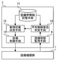
- FIG. 2 shows the configuration of the equipment control device applied to the building equipment management system shown in FIG.
- the equipment device group 1 shown in FIG. 2 represents one of the equipment devices group 1 (air conditioning equipment group 1a, lighting equipment group 1b) shown in FIG.
- the equipment device controller 2 shown in FIG. 2 is one of the equipment equipment controllers 2 (air conditioning equipment controller 2a, lighting equipment controller 2b) shown in FIG. This is representative.
- the equipment device controller 2 includes equipment state monitoring means 9, average control necessity determination means 10, equipment group information storage means 11, control object determination means 12, and equipment control means 13.
- the equipment state monitoring means 9 monitors the operating state of each of the plurality of equipment devices constituting the equipment device group 1. And it detects that the operating state of at least any one of the some installation apparatus which comprises the installation apparatus group 1 changed.
- each equipment apparatus air conditioning equipment and lighting equipment which comprises the equipment equipment group 1 (the air conditioning equipment group 1a and the lighting equipment group 1b) is a switch for changing the operating state. Etc. are provided. The user of the facility equipment can change the desired facility equipment constituting the equipment group 1 to a desired operating state by operating the operation means.
- the average control necessity determination means 10 is a facility that constitutes the equipment group 1 to which the equipment that has detected the change in the operating state belongs. Determine whether the device needs to be controlled. The determination as to whether or not this control is necessary is performed based on the average operating state of the equipment that constitutes the equipment group 1 to which the equipment that has detected a change in the operating state belongs.
- the equipment group information storage means 11 stores in advance a correspondence relationship to which equipment equipment group 1 each equipment installed in the building belongs.
- the average control necessity determination means 10 first refers to the correspondence stored in the equipment group information storage means 11, and the equipment to which the equipment whose operating state change is detected by the equipment status monitoring means 9 belongs. Group 1 is identified. Next, it is specified by referring to the correspondence stored in the facility group information storage means 11 which equipment is included in the specified equipment group 1. Then, based on the specified information, the operating state of each equipment device constituting the equipment device group 1 is acquired via the equipment state monitoring means 9.
- the average control necessity determination means 10 calculates the average of the acquired operating states of the respective facility devices, so that the facility devices constituting the facility device group 1 to which the facility devices in which the change in the operating state is detected belong. Find the average operating condition. Then, the average control necessity determination means 10 compares the average operating state thus obtained with a predetermined reference value, thereby determining the facility device group 1 to which the facility device in which the change in the operating state is detected belongs. It is determined whether or not the facility equipment to be configured needs to be controlled.
- the control target determining means 12 Determine the equipment to be controlled.
- the equipment to be controlled is selected from the equipment constituting the equipment group 1 to which the equipment whose operating state has been detected by the equipment state monitoring means 9 belongs. At this time, however, the equipment for which the change in the operating state is detected by the equipment state monitoring means 9 is excluded from the target.
- the priority order of the equipment to be determined as a control target may be determined in advance and stored in the equipment group information storage unit 11.
- the priority order of the air conditioning equipment determined as the control target may be determined by the measured value of the indoor thermometer. Furthermore, in the case of the lighting equipment group 1b, the priority order of the lighting equipment determined as the control target may be determined based on the measurement value of the indoor illuminometer.
- the facility control means 13 controls the operating state of the equipment in the equipment group 1 determined as the control target by the control target determination means 12. As a result of this control, the operation state control is such that the average operation state of each facility device constituting the facility device group 1 conforms to the reference value used for determination by the average control necessity determination means 10. It is done to become.
- the control of the equipment by the equipment control means 13 may be achieved, for example, by outputting a control signal, or may be achieved by opening / closing a contact such as a relay.
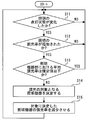
- the control device for equipment operates according to a series of flows shown in FIG.
- the equipment group 1 is the lighting equipment group 1b
- the operating state of the facility equipment group 1 is the lighting state of the lighting equipment group 1b
- the average of the equipment constituting the equipment device group 1 used for determination by the average control necessity determination unit 10 is used.
- a typical operating state is the lighting rate of the lighting equipment which comprises the lighting equipment group 1b.
- step S1 the equipment state monitoring means 9 confirms whether or not the lighting state of the lighting equipment of the lighting equipment group 1b has changed.
- the process proceeds to the next step S2.
- step S2 it is confirmed whether or not the change in the lighting state of the lighting equipment in step S1 is lighting of the lighting equipment.
- the process proceeds to step S3.
- the change in the lighting state of the lighting equipment is not lighting of the lighting equipment but off, the process returns to step S1.
- step S3 the average control necessity determination means 10 confirms whether or not the number of lighting fixtures constituting the lighting fixture group 1b to which the lighting fixture whose lighting state has changed in step S1 belongs is equal to or less than a specified value.
- the specified value can be calculated by multiplying the reference lighting rate by the total number of lighting equipments constituting the focused lighting equipment group 1b. Specifically, for example, when the lighting rate as a reference is 80% and the lighting equipment group 1b of interest is composed of 50 lighting equipments, the specified value is 40.
- step S3 if the number of lighting of the lighting equipment constituting the focused lighting equipment group 1b is equal to or less than a specified value, the lighting rate of the lighting equipment constituting the focused lighting equipment group 1b is set as a reference lighting. Since it is less than the rate, the process returns to step S1. On the other hand, in step S3, when the lighting number of the lighting equipment which comprises the focused lighting equipment group 1b exceeds the regulation value, it progresses to step S4.
- step S4 the control object determining means 12 determines the lighting equipment to be turned off from the lighting equipment group 1b of interest. At this time, the lighting equipment in which the change in the lighting state is detected in step S1 is excluded from the control target. By doing in this way, the situation where the lighting installation turned on by the user will be automatically turned off immediately after that can be avoided.
- step S4 the process proceeds to step S5.
- step S5 the equipment control means 13 turns off the lighting equipment determined as the target of the turn-off control in step S4.
- step S5 the process returns to step S1.
- the lighting rate in the lighting equipment group 1b is regularly checked every time a certain time elapses. Confirmation may be performed.
- the equipment control apparatus configured as described above includes a monitoring unit that detects that the operating state of at least one of a plurality of equipment constituting the equipment group has changed, and the equipment by the monitoring means.
- the facility device group is configured based on the average operating state of each facility device that configures the facility device group to which the facility device in which the change in the operating state is detected belongs.
- Necessity determining means for determining the necessity of control of the equipment and the equipment constituting the equipment apparatus group when the necessity determining means determines that the control of the equipment constituting the equipment apparatus group is necessary.
- the devices there are a control target determining means for determining a control target from equipment other than the equipment whose operating state is detected by the monitoring means, and a control target equipment determined by the control target determining means.
- Gosuru control means is those with.
- each facility device is maintained without pre-setting the control conditions for each facility device, while keeping the power consumption of the entire facility device group within the specified range. Accordingly, it is possible to automatically perform control so that a facility device required by the user is operated and an unnecessary configuration device is not operated.
- FIG. FIG. 4 is a flowchart according to Embodiment 2 of the present invention and showing the operation of the control device for equipment.
- the equipment is controlled so that the average operating state of each equipment constituting the equipment group meets a predetermined standard. there were.
- the installation apparatus was lighting equipment, and the example which made the average operation state which is the reference
- the equipment when the operating state of the equipment is changed, the equipment is controlled so that the average operating state of each equipment constituting the equipment group meets a predetermined standard.
- a predetermined standard As an example of the above, an example will be described in which the equipment is lighting equipment, and the average operating state, which is a reference for control, is the average dimming rate of the lighting equipment.
- step S11 of FIG. 4 the equipment state monitoring means 9 confirms whether or not the lighting state of the lighting equipment of the lighting equipment group 1b has changed.
- the process proceeds to the next step S12.
- step S12 it is confirmed whether or not the change in the lighting state of the lighting equipment in step S11 is an increase in the dimming rate of the lighting equipment. If the change in the lighting state of the lighting equipment is an increase in the dimming rate of the lighting equipment, the process proceeds to step S13.
- the change in the lighting state of the lighting equipment is not an increase in the dimming rate of the lighting equipment but a decrease, the process returns to step S11.
- step S13 the average control necessity determination means 10 determines whether or not the average dimming rate of the lighting equipment constituting the lighting equipment group 1b to which the lighting equipment whose lighting state has changed in step S11 is equal to or less than a specified value. Check.
- step S13 if the average dimming rate of the lighting equipment constituting the lighting equipment group 1b of interest is not more than the specified value, the process returns to step S11. On the other hand, when the average dimming rate of the lighting equipment constituting the lighting equipment group 1b of interest exceeds the specified value, the process proceeds to step S14.
- step S14 the control target determining means 12 determines the lighting equipment that is subject to dimming control from the lighting equipment group 1b of interest. At this time, the lighting equipment in which the change in the lighting state is detected in step S11 is excluded from the control target.
- step S15 the equipment control means 13 reduces the lighting equipment determined as the dimming control target in step S14 so that the average dimming rate in the lighting equipment group 1b of interest is below a specified value. Shine. After step S15, the process returns to step S11.
- the same effects as in the first embodiment can be obtained.
- This will be specifically described with reference to the example described in the second embodiment.
- the dimming rate of the lighting equipment is increased by the user's operation and the average dimming rate in the lighting equipment group exceeds 50%, the lighting equipment other than the lighting equipment for which the dimming rate has been increased immediately before The dimming rate of the lighting equipment is automatically reduced.
- the average dimming rate of the lighting equipment is suppressed to 50% or less, depending on the situation at that time. It is possible to automatically control to the state where the dimming rate necessary for each lighting equipment is obtained.
- the control of the operating state of the lighting equipment has been described as an example.
- the present invention can be similarly applied to other equipment other than the lighting equipment. it can.
- air conditioning equipment it is conceivable to automatically control the on / off state of operation, switching between cooling or heating operation and air blowing operation, the adjustment state of air volume during operation, and the like.
- FIG. FIG. 5 relates to Embodiment 3 of the present invention and is a flowchart showing the operation of the control device for equipment.
- the facility device when the operating state of the facility device changes, the facility device is configured so that the average operating state of each facility device constituting the facility device group conforms to a predetermined standard. Was to control.
- the control target value of the equipment when the control target value of the equipment is changed, the average control target value of each equipment constituting the equipment group is adapted to a predetermined standard.
- the control target value of the equipment is controlled.
- the equipment is an air conditioning facility
- an average control target value that is a reference for control is an average value of the set temperature of the air conditioning facility.
- the equipment device controller 2 includes equipment state monitoring means 9, average control necessity determination means 10, equipment group information storage means 11, control object determination means 12, and equipment control means 13.
- the equipment state monitoring means 9 monitors the control target value set for each of the plurality of equipment devices constituting the equipment device group 1. And it detects that the control target value of at least any one of the some installation apparatus which comprises the installation apparatus group 1 changed.
- each equipment apparatus air conditioning equipment and lighting equipment which comprises the equipment equipment group 1 (air conditioning equipment group 1a and lighting equipment group 1b) changes the setting of the control target value.
- An operation means such as a switch is provided. The user of the equipment can change the control target value of the desired equipment constituting the equipment group 1 to a desired one by operating the operation means.
- the average control necessity determination means 10 constitutes the equipment device group 1 to which the equipment device in which the change in the control target value is detected belongs. It is determined whether or not the control target value of the equipment to be changed needs to be changed. The determination as to whether or not the control target value needs to be changed is made based on the average value of the control target values of the facility devices that constitute the facility device group 1 to which the facility device in which the change in the control target value is detected belongs.
- the average control necessity determination means 10 first refers to the correspondence stored in the equipment group information storage means 11, and the equipment to which the equipment whose change in the control target value is detected by the equipment state monitoring means 9 belongs. Group 1 is identified. Next, it is specified by referring to the correspondence stored in the facility group information storage means 11 which equipment is included in the specified equipment group 1. And based on this specified information, the control target value of each facility apparatus which comprises the facility apparatus group 1 is acquired via the installation state monitoring means 9. FIG.
- the average control necessity determination means 10 calculates an average value of the acquired control target values of each facility device. Then, the average control necessity determination means 10 compares the average value of the control target values obtained in this way with a predetermined reference value, so that the equipment group to which the equipment whose change in the control target value is detected belongs. It is determined whether or not it is necessary to change the control target value for the equipment constituting 1.
- the average control necessity determination means 10 determines that it is necessary to change the control target value for the equipment constituting the equipment group 1 to which the equipment whose change in the control target value is detected belongs, the control target is determined.
- the means 12 determines the equipment for which the control target value is to be changed.
- the equipment for which the control target value is to be changed is selected from the equipment constituting the equipment group 1 to which the equipment whose change in the control target value is detected by the equipment state monitoring means 9 belongs. At this time, however, the equipment whose change in the control target value is detected by the equipment state monitoring means 9 is excluded from the target.
- the facility control unit 13 changes the control target value of the facility device of the facility device group 1 determined by the control target determination unit 12 as the target of the control target value change.
- the change of the control target value is such that the average value of the control target values of the respective equipment constituting the equipment group 1 conforms to the reference value used for the determination by the average control necessity determination means 10. To be done.
- the operation of the equipment control apparatus according to Embodiment 3 will be described with reference to FIG.
- the equipment group 1 is the air conditioning equipment group 1a and the control target value of the equipment equipment group 1 is the set temperature of the air conditioning equipment group 1a will be described.
- step S21 the equipment state monitoring means 9 confirms whether or not the set temperature of the air conditioning equipment constituting the air conditioning equipment group 1a has changed.
- the process proceeds to the next step S22.
- step S22 it is confirmed whether or not the change in the set temperature of the air conditioning equipment in step S21 is an increase in the set temperature.
- the process proceeds to step S23.
- the set temperature of the air conditioning equipment is not an increase but a decrease, the process returns to step S21.
- step S23 the average control necessity determination means 10 confirms whether or not the average set temperature of the air conditioning equipment constituting the air conditioning equipment group 1a to which the air conditioning equipment whose set temperature has changed in step S21 is equal to or less than a specified value. To do.
- step S23 if the average set temperature of the air-conditioning equipment constituting the air-conditioning equipment group 1a of interest is not more than the specified value, the process returns to step S21. On the other hand, when the average set temperature of the air conditioning equipment constituting the air conditioning equipment group 1a of interest exceeds the specified value, the process proceeds to step S24.
- step S24 the control target determining means 12 determines the air conditioning equipment that is the target of changing the set temperature from the air conditioning equipment group 1a of interest. At this time, the air conditioning equipment in which the change in the set temperature is detected in step S21 is excluded from the change target.
- step S24 the process proceeds to step S25.
- the facility control means 13 determines that the set temperature of the air conditioning equipment determined as the target of the set temperature change in step S24 is such that the average value of the set temperatures in the air conditioning facility group 1a of interest is not more than the specified value. Change to After step S25, the process returns to step S21.
- the equipment control device configured as described above includes a monitoring unit that detects that a control target value of at least one of a plurality of equipment constituting the equipment group has changed, and a facility by the monitoring unit.
- the facility device is determined based on the average value of the control target values of the facility devices that constitute the facility device group to which the facility device in which the change in the control target value is detected belongs.
- the necessity judgment means determines that the control of the equipment that constitutes the equipment apparatus group is necessary.
- Control object determination means for determining a target of change of the control target value from equipment other than the equipment whose change in the control target value is detected by the monitoring means among the equipment constituting the equipment group, and control target determination To the means And control means for changing the control target value of the determined control target equipment Ri are those having a.
- the power consumption of other equipment belonging to the equipment device group can be automatically controlled so as to reduce. Accordingly, it is possible to suppress an increase in the power consumption of the entire equipment group before and after the change of the control target value by the user.
- the example given here is an example of keeping the power consumption within the specified range by setting the average value of the set temperature to a reference value or less when performing heating operation in winter.
- the present invention can be used for, for example, a control device for equipment that controls the operating states and control target values of a plurality of equipment installed in a building or facility such as a building.
Landscapes
- Engineering & Computer Science (AREA)
- Automation & Control Theory (AREA)
- Computer Networks & Wireless Communication (AREA)
- Signal Processing (AREA)
- General Engineering & Computer Science (AREA)
- Physics & Mathematics (AREA)
- General Physics & Mathematics (AREA)
- Air Conditioning Control Device (AREA)
Abstract
La présente invention concerne un dispositif qui est destiné à commander des équipements d'installation et qui peut commander des équipements d'installation de manière à avoir une condition de fonctionnement appropriée qui est conforme au niveau de nécessité de chaque équipement d'installation, même sans prérégler des conditions de commande ou analogues pour chaque équipement d'installation. Ainsi, le dispositif pour commander des équipements d'installation est pourvu : d'un moyen de surveillance qui détecte la condition de fonctionnement d'une pluralité d'équipements d'installation, qui configurent un groupe d'équipements d'installation, qui a changé ; d'un moyen de détermination de nécessité qui, lorsqu'un changement de la condition de fonctionnement des équipements d'installation a été détecté, détermine la nécessité de commander les équipements d'installation qui configurent le groupe d'équipements d'installation en fonction d'une condition de fonctionnement moyenne de chaque équipement d'installation qui configure le groupe d'équipements d'installation auquel appartient l'équipement d'installation pour lequel un changement de condition de fonctionnement a été détecté ; d'un moyen de détermination de sujet de commande qui, lorsqu'il a été déterminé que la commande des équipements d'installation qui configurent le groupe d'équipements d'installation est nécessaire, détermine un sujet de commande à partir des équipements d'installation à part l'équipement d'installation pour lequel un changement de condition de fonctionnement a été détecté par le moyen de surveillance parmi les équipements d'installation qui configurent le groupe d'équipements d'installation ; et d'un moyen de commande qui commande l'équipement d'installation qui a été déterminé être le sujet de commande.
Priority Applications (1)
| Application Number | Priority Date | Filing Date | Title |
|---|---|---|---|
| PCT/JP2012/067903 WO2014010076A1 (fr) | 2012-07-13 | 2012-07-13 | Dispositif pour commander des équipements d'installation |
Applications Claiming Priority (1)
| Application Number | Priority Date | Filing Date | Title |
|---|---|---|---|
| PCT/JP2012/067903 WO2014010076A1 (fr) | 2012-07-13 | 2012-07-13 | Dispositif pour commander des équipements d'installation |
Publications (1)
| Publication Number | Publication Date |
|---|---|
| WO2014010076A1 true WO2014010076A1 (fr) | 2014-01-16 |
Family
ID=49915578
Family Applications (1)
| Application Number | Title | Priority Date | Filing Date |
|---|---|---|---|
| PCT/JP2012/067903 Ceased WO2014010076A1 (fr) | 2012-07-13 | 2012-07-13 | Dispositif pour commander des équipements d'installation |
Country Status (1)
| Country | Link |
|---|---|
| WO (1) | WO2014010076A1 (fr) |
Citations (4)
| Publication number | Priority date | Publication date | Assignee | Title |
|---|---|---|---|---|
| JP2005061801A (ja) * | 2003-08-20 | 2005-03-10 | Ken Facilities:Kk | 空調機器の管理システム及びコンピュータプログラム |
| JP2009240032A (ja) * | 2008-03-26 | 2009-10-15 | Panasonic Electric Works Co Ltd | デマンド制御システム |
| JP2009240054A (ja) * | 2008-03-26 | 2009-10-15 | Panasonic Electric Works Co Ltd | デマンド制御システム、デマンド制御方法 |
| JP2011010497A (ja) * | 2009-06-29 | 2011-01-13 | Mitsubishi Electric Corp | 制御装置 |
-
2012
- 2012-07-13 WO PCT/JP2012/067903 patent/WO2014010076A1/fr not_active Ceased
Patent Citations (4)
| Publication number | Priority date | Publication date | Assignee | Title |
|---|---|---|---|---|
| JP2005061801A (ja) * | 2003-08-20 | 2005-03-10 | Ken Facilities:Kk | 空調機器の管理システム及びコンピュータプログラム |
| JP2009240032A (ja) * | 2008-03-26 | 2009-10-15 | Panasonic Electric Works Co Ltd | デマンド制御システム |
| JP2009240054A (ja) * | 2008-03-26 | 2009-10-15 | Panasonic Electric Works Co Ltd | デマンド制御システム、デマンド制御方法 |
| JP2011010497A (ja) * | 2009-06-29 | 2011-01-13 | Mitsubishi Electric Corp | 制御装置 |
Similar Documents
| Publication | Publication Date | Title |
|---|---|---|
| US12346142B2 (en) | Controlling the setback and setback recovery of a power-consuming device | |
| EP1950505B1 (fr) | Système pour le contrôle de la demande d'un climatiseur d'air multiple | |
| CN103958976B (zh) | 用于提高hvac系统的能效的方法和系统 | |
| EP2701262A1 (fr) | Dispositif de commande électrique, système de commande et procédé de commande | |
| KR101278638B1 (ko) | 스마트 에너지 관리 시스템 및 그 제어 방법 | |
| US10027167B2 (en) | Load control system | |
| KR101834776B1 (ko) | 서버에서 재가공된 정보를 통해 스카다 장치를 통합 제어하는 시스템 | |
| JP5389618B2 (ja) | 空気調和機の制御システム | |
| KR20140120134A (ko) | 재실 감지 센서를 이용한 에너지 관리 시스템 및 방법 | |
| JP5113568B2 (ja) | 環境制御システム | |
| JP5951270B2 (ja) | 空気調和機の消費電力量管理制御システム、サーバ装置、クライアント装置及び空気調和機の消費電力量管理制御方法 | |
| KR101921536B1 (ko) | 공기조화기 시스템 | |
| JP6815464B2 (ja) | ローカル管理装置、サーバ管理装置、及び管理方法 | |
| WO2014010076A1 (fr) | Dispositif pour commander des équipements d'installation | |
| JP6487524B2 (ja) | 管理装置及び管理方法 | |
| KR20160009117A (ko) | 빌딩 자동 제어 시스템 | |
| KR20090048791A (ko) | 전력 제어 시스템 | |
| JP6272039B2 (ja) | エネルギー管理装置及びエネルギー管理方法 | |
| KR20110056062A (ko) | 디멘드 제어 시스템 및 그 제어방법 | |
| JP6464336B1 (ja) | 業務用インバータエアコンの個別電力可視化削減方法 | |
| KR101913596B1 (ko) | 자동 조명 제어 설비를 이용한 무선 냉난방 제어 시스템 및 방법 | |
| KR102014152B1 (ko) | 온도제어를 포함하는 최대전력관리장치와 주제어장치의 스마트제어기 | |
| JP2013092338A (ja) | 空調システム制御装置 | |
| KR20150115145A (ko) | 피크전력 제어 장치 |
Legal Events
| Date | Code | Title | Description |
|---|---|---|---|
| 121 | Ep: the epo has been informed by wipo that ep was designated in this application |
Ref document number: 12881056 Country of ref document: EP Kind code of ref document: A1 |
|
| NENP | Non-entry into the national phase |
Ref country code: DE |
|
| 122 | Ep: pct application non-entry in european phase |
Ref document number: 12881056 Country of ref document: EP Kind code of ref document: A1 |
|
| NENP | Non-entry into the national phase |
Ref country code: JP |