WO2014010084A1 - Système de montage de composants - Google Patents
Système de montage de composants Download PDFInfo
- Publication number
- WO2014010084A1 WO2014010084A1 PCT/JP2012/067981 JP2012067981W WO2014010084A1 WO 2014010084 A1 WO2014010084 A1 WO 2014010084A1 JP 2012067981 W JP2012067981 W JP 2012067981W WO 2014010084 A1 WO2014010084 A1 WO 2014010084A1
- Authority
- WO
- WIPO (PCT)
- Prior art keywords
- component
- feeder
- mounting machine
- traveling
- mounting
- Prior art date
- Legal status (The legal status is an assumption and is not a legal conclusion. Google has not performed a legal analysis and makes no representation as to the accuracy of the status listed.)
- Ceased
Links
Images


Classifications
-
- H—ELECTRICITY
- H05—ELECTRIC TECHNIQUES NOT OTHERWISE PROVIDED FOR
- H05K—PRINTED CIRCUITS; CASINGS OR CONSTRUCTIONAL DETAILS OF ELECTRIC APPARATUS; MANUFACTURE OF ASSEMBLAGES OF ELECTRICAL COMPONENTS
- H05K13/00—Apparatus or processes specially adapted for manufacturing or adjusting assemblages of electric components
- H05K13/02—Feeding of components
- H05K13/021—Loading or unloading of containers
-
- H—ELECTRICITY
- H05—ELECTRIC TECHNIQUES NOT OTHERWISE PROVIDED FOR
- H05K—PRINTED CIRCUITS; CASINGS OR CONSTRUCTIONAL DETAILS OF ELECTRIC APPARATUS; MANUFACTURE OF ASSEMBLAGES OF ELECTRICAL COMPONENTS
- H05K13/00—Apparatus or processes specially adapted for manufacturing or adjusting assemblages of electric components
- H05K13/08—Monitoring manufacture of assemblages
- H05K13/086—Supply management, e.g. supply of components or of substrates
Definitions
- the present invention relates to a component mounting system that can automatically supply components to a plurality of mounting machine modules.
- a component storage for storing a tape feeder containing a large number of components is provided at a position distant from the mounter module, and a large number of tape feeders are provided in the component storage.
- a storage shelf is provided to store the items.
- the present invention has been made to solve the above-described conventional problems, and the replenishment unit mounted on the traveling body capable of traveling between the component storage and the plurality of mounting machine modules automatically supplies the components.
- An object of the present invention is to provide a component mounting system that can be performed automatically.
- a feature of the invention according to claim 1 is that in a component mounting system in which a plurality of mounting machine modules having mounting heads are arranged along the circuit board conveyance direction, a plurality of components of different types are used.
- a component storage for storing the component supply element, a traveling body capable of traveling between the component storage and the plurality of mounting machine modules, and provided on the traveling body, parallel to a traveling direction of the traveling body
- a movable table movable in any direction, and mounted on the movable table, supporting the component supply element, supplying the component supply element to the plurality of mounting machine modules, and collecting from the plurality of mounting machine modules
- a replenishment unit, and the same configuration of the traveling body and the moving base for the plurality of component supply elements is made common, and a plurality of common base stands each mounting the replenishment unit are provided,
- a replenishment unit that supports at least one of the above-described component supply elements among a tape feeder, a component tray, and a bulk cassette each containing components of different component types is mounted on the plurality of common base tables. That is.
- a feature of the invention according to claim 2 is that in claim 1, the replenishment unit supports a plurality of the component supply elements.
- a guide rail and a first meshing body parallel to the guide rail are fixed to the front surface of the plurality of mounting machine modules, respectively, and the running
- the body includes a follower roller that engages with the guide rail, a second meshing body that meshes with the first meshing body, and a traveling motor that rotates the second meshing body.
- an unmanned conveyance system according to the first or second aspect, wherein the traveling body is guided by a guideline laid along a plurality of the mounting machine modules and can travel on a floor surface. It is made up of trolleys.
- At least two component supply elements of the tape feeder, the component tray, and the bulk cassette are provided by the replenishment unit mounted on the traveling body that can be transported between the component storage and the plurality of mounting machine modules. Can be replenished to a plurality of mounting machine modules and collected from a plurality of mounting machine modules, so that necessary parts can be automatically and efficiently replenished, and labor saving and automation can be achieved. .
- FIG. 1 is a schematic plan view showing an entire component mounting system according to a first embodiment of the present invention. It is a schematic plan view which shows a mounting machine module. It is a perspective view of the mounting machine module which shows an example of the feeder replenishment unit which comprises a replenishment apparatus. It is a perspective view of the mounting machine module which shows an example of the tray supply unit which comprises a supply apparatus. It is a figure which shows the moving apparatus which moves a moving stand. It is a figure which shows the positioning means which positions an automatic guided vehicle. It is a figure which shows the feed mechanism of a feeder replenishment unit. It is a figure which shows the barcode reader which reads the barcode of a tape feeder or a tray. It is a figure which shows a non-contact transmission apparatus.
- FIG. 1 shows a component mounting system 10 according to a first embodiment of the present invention.
- the component mounting system 10 includes a printer module 11 that prints solder on a circuit board B, and an electronic circuit on the circuit board B.
- a work module 13 comprising a plurality of mounter modules 12 for mounting parts (hereinafter simply referred to as parts), a parts storage 14 for storing a large number of parts of different parts, and these work modules 13 and parts storage 14
- a plurality of replenishing devices 15 for replenishing parts and collecting parts are provided.
- the printing machine module 11 and the plurality of mounting machine modules 12 constituting the work module 13 are arranged along the conveyance direction (X-axis direction) of the circuit board B, and the work module 13 is Y which is orthogonal to the X-axis direction. Two rows are arranged in parallel so as to face each other with a predetermined distance in the axial direction. A plurality of replenishing devices 15 are movably provided along two rows of work modules 13 (hereinafter referred to as first work module 13A and second work module 13B).
- the parts storage 14 is disposed at a position separated from the first and second work modules 13A and 13B in the X-axis direction.
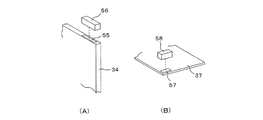
- the parts storage 14 includes a plurality of tape feeders 34 (see FIG. 8A) that accommodate parts having different parts types, and a plurality of part trays 37 (see FIG. 8B) that accommodate parts having different parts types. ) Are aligned and stored in a storage shelf (not shown), and a tape feeder 34 and a component tray 37 containing necessary components are supplied to the supply device 15 by an operator.
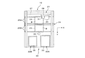
- the plurality of mounting machine modules 12 include a component mounting device 21, a component supply device 22, a substrate holding device 23, and a substrate transport device 24.
- the board transport device 24 has two rows of belt conveyors 25A and 25B that transport the circuit board B in the X-axis direction.
- the circuit board B is transported along the belt conveyors 25A and 25B and placed on the board holding device 23. While carrying in, it carries out from the board
- the substrate holding device 23 includes a substrate support device that supports the circuit board B carried in by the substrate transfer device 24 from below, and a clamp device that positions and clamps the circuit board B.
- the component mounting device 21 includes a Y-axis slide 27 supported above the board holding device 23 so as to be movable in the Y-axis direction, and an X-axis slide 28 supported on the Y-axis slide 27 so as to be movable in the X-axis direction. And a mounting head 30 mounted on the X-axis slide 28. Although not shown, the mounting head 30 is provided with a suction nozzle for sucking and holding components.
- the Y-axis slide 27 and the X-axis slide 28 are respectively moved by an X-axis direction moving device and a Y-axis direction moving device using a servo motor with an encoder as a drive source, and the mounting head 30 can be moved to an arbitrary position in the XY plane. I am doing so.
- a substrate imaging device 31 composed of a CCD camera is provided on the X-axis slide 28, and the substrate imaging device 31 includes a substrate position reference mark and a substrate provided on the circuit board B positioned on the substrate holding device 23.
- An ID mark is imaged to obtain substrate position reference information and substrate ID information.
- substrate imaging device 31 while correcting the position of the mounting head 30 with respect to the circuit board B to XY direction, it is based on the board
- the component mounting operation is controlled.
- the circuit board B can be mounted in a predetermined posture at a predetermined coordinate position.
- the component supply device 22 includes, as an example, a feeder-type component supply device 22A and a tray-type component supply device 22B.
- the feeder-type component supply device 22A is a component supply element that is detachably attached to the feeder support base 33.
- the plurality of tape feeders 34 are arranged in parallel in the X-axis direction.
- the tape feeder 34 is wound with a tape containing a large number of parts at intervals, and the tapes are intermittently sent out by a sprocket driven by a motor (not shown) built in the tape feeder 34, thereby providing parts. Can be sequentially supplied to a predetermined component supply position.
- the tape feeder 34 is detachably attached to a slot provided in the feeder support base 33.
- a connector (not shown) is connected. Then, power is supplied from the feeder support base 33 to the tape feeder 34, and necessary control signals (part request signal, part supply completion signal, etc.) between the control part of the tape feeder 34 and the control part of the feeder support base 33 are provided. ) And management information such as the ID of the tape feeder 34 are transmitted.
- the tray-type component supply device 22B includes a housing 35 in which a stocker (not shown) is accommodated so as to be movable up and down.
- the stocker is provided with a plurality of tray storage shelves in which a plurality of component trays 37 serving as component supply elements that store and hold a large number of components are arranged in the vertical direction, and the component trays 37 accommodated in these tray storage shelves are It is pulled out from the stocker in the Y-axis direction and positioned at the component supply position.
- feeder-type component supply device 22A and the tray-type component supply device 22B described above are well known, and as the feeder-type component supply device 22A, for example, JP 2012-104635 A related to the application of the same applicant as this case.
- the tray-type component supply device 22B for example, the technology described in Japanese Patent Application Laid-Open No. 2009-147197 related to the same applicant as the present application can be used.
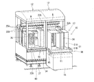
- the replenishing device 15 includes an unmanned transport carriage 16 as a traveling body that can travel along the work modules 13 ⁇ / b> A and 13 ⁇ / b> B, and a replenishment unit 17 mounted on the unmanned transport cart 16. have.
- the replenishing device 15 conveys the component supply elements 34 and 37 to be replenished to the mounting machine module 12 and the component supply elements 34 and 37 to be collected from the mounting machine module 12, and each of the work modules 13 ⁇ / b> A and 13 ⁇ / b> B.
- a plurality are provided.
- an unmanned transport cart 16 On the floor surface on the front side of each work module 13, an unmanned transport cart 16 is provided so as to be able to travel along the X-axis direction. These unmanned transport carts 16 are embedded in the floor along the work modules 13A and 13B. The magnetic guide action of the guideline 90 is conveyed between the parts storage 14 and the work module 13.
- the guideline 90 includes a guideline 90A laid along the front surface of the first work module 13A, a guideline 90B laid along the front surface of the second work module 13B, and these guideline 90A, 90B.
- the end portions are configured in an endless manner by the guideline 90C for connecting the end portions of each other.
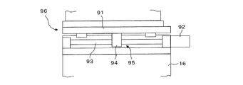
- a movable table 91 that holds a supply unit described later is guided and supported so as to be movable in the X-axis direction by a guide mechanism (not shown).
- the movable table 91 can be moved in the X-axis direction by a moving device 95 including a ball screw 93 driven by a motor 92 and a feed nut 94 screwed to the ball screw 93.
- the plurality of automatic guided vehicles 16 and the movable table 91 are commonly used so as to have the same configuration with respect to a plurality of component supply elements, and constitute a plurality of common base tables 96. Then, a feeder supply unit 51 or a tray supply unit 52 that supports the tape feeder 34 or the component tray 37 is mounted on the plurality of common base tables 96, respectively.
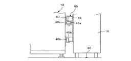
- a pair of positioning pins 97 constituting positioning means are provided on the front surface of the mounting machine module 12 as shown in FIG.
- the pair of positioning pins 97 are moved forward to set the stop position of the automatic guided carriage 16 at a position separated in the X-axis direction. to correct.
- the automatic guided vehicle 16 can be positioned at an accurate position with respect to the mounting machine module 12.
- the unmanned conveyance cart 16 may be provided with a guide roller 98 that can come into contact with the front surface of the mounting machine module 12, and the unmanned conveyance cart 16 may be placed while the guide roller 98 is always in contact with the front surface of the mounting machine module 12. By running, the gap between the mounting machine module 12 and the automatic guided vehicle 16 can be kept constant.
- the automatic guided vehicle 16 is equipped with a motor as a travel drive source. Electric power is supplied to the motor from the work modules 13A and 13B by a non-contact transmission device 65, which will be described later.
- the carriage 16 is transported and controlled.
- a battery as a motor power source is built in the automatic guided vehicle 16, and the automatic transfer cart 16 is controlled to be transported by this battery, and the parts are replenished in each mounting machine module 12, and the non-contact transmission device 65.
- the electric power supplied in a non-contact manner may be stored in the battery.
- the replenishment unit 17 mounted on the automatic guided carriage 16 of the replenishing device 15 includes a feeder replenishment unit 51 that holds the tape feeder 34 and a tray replenishment unit 52 that holds the component tray 37.
- the feeder replenishment unit 51 and the tray replenishment unit 52 are mounted on the plurality of automatic transport carts 16.
- the feeder replenishment unit 51 can accommodate a plurality of tape feeders 34.
- the feeder replenishment unit 51A for replenishing the tape feeders 34 to the feeder support base 33 of the mounting machine module 12 and the plurality of tape feeders 34 can be accommodated.
- a feeder collection unit 51 ⁇ / b> B that collects the tape feeder 34 from the feeder support 33 of the machine module 12 is arranged in parallel in the traveling direction of the automatic guided vehicle 16.
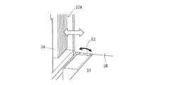
- the feeder replenishing unit 51A holds a plurality of tape feeders 34 arranged side by side in the X-axis direction, and holds these tape feeders 34 so as to be movable in the Y-axis direction.
- the feeder replenishing portion 51 ⁇ / b> A is provided with a feeder feeding mechanism including a feeding roller 53 that contacts the lower surface of each tape feeder 34. By rotating the feeding roller 53, the tape feeder 34 is fed to the feeder. It is sent out in the Y-axis direction from the replenishing part 51A so that it can be mounted in an empty slot of the feeder-type component supply device 22A of the mounting machine module 12.
- the feeder collecting unit 51B is also provided with a feeder feeding mechanism similar to that described above. With this feeder feeding mechanism, the tape feeder 34 to be collected is pulled out from the feeder-type component supply device 22A of the mounting machine module 12, and the feeder collecting unit 51B can be collected.
- the feeder support base 33 of the feeder-type component supply device 22A is provided with a lock mechanism for locking and unlocking the tape feeder 34, and the tape feeder 34 is moved by the locking operation of the lock mechanism.
- the feeder support 33 is pulled in and locked, and is connected to a connector.
- the tape feeder 34 is unlocked and pushed out from the feeder support 33 by the unlocking operation of the lock mechanism, and the connector connection between the tape feeder 34 and the feeder support 33 is released.
- the feeder supply unit 51A is provided with a barcode reader 56 that reads the barcode 55 applied to the tape feeder 34 accommodated in the feeder supply unit 51A. It is possible to verify whether or not the tape feeder 34 storing necessary parts has been replenished without fail.
- a 2D code or RFID may be provided in the tape feeder 34, and the 2D code or RFID may be recognized by a camera or an RFID reader provided in the feeder replenishing unit 51A.
- the tray replenishment unit 52 can accommodate a plurality of component trays 37, and can accommodate a tray replenishment unit 52 ⁇ / b> A that replenishes these component trays 37 to the stocker in the housing 35 of the mounting machine module 12 and a plurality of component trays 37.
- a tray collection unit 52B that collects the component tray 37 from the stocker in the housing 35 of the mounting machine module 12 is arranged in parallel in the traveling direction of the automatic guided vehicle 16.
- the component tray 37 accommodated in the tray replenishing section 52A is fed in the Y-axis direction by a tray feed mechanism (not shown) and replenished to a predetermined storage shelf of the stocker of the tray-type component supply device 22B of the mounting machine module 12. It is like that.
- the tray collecting unit 52B uses the tray feed mechanism (not shown) to draw and collect the empty component tray 37 from the stocker of the tray-type component supply device 22B of the mounting machine module 12 in the Y-axis direction. It has become.
- the tray replenishing section 52A that accommodates the plurality of component trays 37 can be moved up or down, or the tray replenishing section 52A can be accommodated in each stage of the tray replenishing section 52A by using the up and down movement of the stocker of the tray type component supplying apparatus 22B.
- the plurality of component trays 37 can be replenished to a predetermined storage shelf of the stocker.
- the tray supply unit 52A is provided with a barcode reader 58 that reads the barcode 57 attached to the component tray 37 accommodated in the tray supply unit 52A. It is possible to check whether or not the component tray 37 storing the necessary components is definitely supplied.
- the X-axis direction is arranged on the printing machine module 11 and the plurality of mounting machine modules 12 side so that power supply and communication can be performed in a non-contact manner between the work modules 13A and 13B and the replenishing device 15.
- the non-contact transmission unit 63 extending in the form of a non-contact transmission unit 63 is provided on the supply device 15 side so as to face the non-contact transmission unit 63.
- These non-contact transmission unit 63 and non-contact transmission head 64 constitute a non-contact transmission device 65.
- the non-contact transmission device 65 supplies power from the work modules 13A and 13B to the replenishment device 15 or Necessary communication can be performed between the modules 13A and 13B and the replenishing device 15 side.
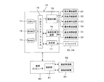
- FIG. 10 shows a control device 70 for controlling each mounting machine module 12, and the control device 70 includes a CPU 71, a ROM 72, a RAM 73, and an input / output interface 74 connected thereto.
- the input / output interface 74 displays image data captured by the component mounting apparatus 21, the component supply apparatus 22, the board holding apparatus 23, and the board transport apparatus 24, the board imaging apparatus 31, and the component imaging apparatus 32.
- An image processing device 76 to be processed and a collation unit 77 for collating information read by the barcode readers 56 and 58 are connected.
- the ROM 72 of the control device 70 stores data such as the part model number, dimensions, and the number of parts accommodated for each serial ID of the parts accommodated in the tape feeder 34 and the part tray 37. Thereby, when the serial ID of the component is acquired by the barcode readers 56 and 58, the model number of the component can be recognized.
- the control device 70 is connected to a management computer 80 that controls the work modules 13A and 13B and the parts storage 14 in an integrated manner.
- the management computer 80 includes a control unit 81 that integrally controls the first and second work modules 13A and 13B, and a replenishment control that replenishes the replenishment device 15 and a replenishment control that replenishes the replenishment device 15.
- a control unit 83 is connected.
- the circuit board B is sequentially transferred to the printing machine module 11 and the mounting machine module 12 by the board transfer device 24.
- solder is printed on the transferred circuit board B.
- the components are mounted on the conveyed circuit board B according to a predetermined program by the component mounting apparatus 21.
- each mounting machine module 12 the remaining number of parts is managed every time a part is taken out from the tape feeder 34 or the component tray 37, and when a part runs out in a certain tape feeder 34 or a certain component tray 37,
- the control device 70 instructs the management computer 80 to supply parts.
- an operator in the component storage unit 14 needs to supply components to the feeder supply unit 51 or the tray supply unit 52 of the supply device 15 waiting in the component storage unit 14.
- a command is issued to replenish the tape feeder 34 or the component tray 37 containing the product type.
- the tape feeder 34 that accommodates a component type A component runs out, the tape feeder that accommodates the component type A component in the feeder replenishment unit 51 ⁇ / b> A of the feeder replenishment unit 51. 34 is set.
- the barcode 55 of the tape feeder 34 is read by the barcode reader 56, and the serial ID of the tape feeder 34 is connected to the parts storage 14. It is transmitted to the management computer 80. Since the management computer 80 stores data related to parts for each serial ID, the tape feeder 34 set in the feeder replenishing section 51A is the same type as the replenished parts instructed by the control device 70 of the mounting machine module 12. It is collated by the collation unit 77 whether or not it is. If the supply component set in the feeder supply unit 51A is wrong, an operator in the component storage 14 is notified of a verification error.
- the unmanned transport carriage 16 replenishes the parts from the parts storage 14 by electromagnetic induction according to the guideline 90 (90A, 90B). Is delivered toward the mounting machine module 12 that requires the.
- the replenishing device 15 (unmanned transport cart 16) travels to a predetermined mounting machine module 12, the unmanned transport cart 16 is stopped at a predetermined position based on a detection signal from an unillustrated sensor or the like.
- the pair of positioning pins 97 are moved forward, the position of the automatic guided vehicle 16 in the X-axis direction is corrected, and the replenishing device 15 is set to an accurate position determined with respect to the mounting machine module 12. Is positioned.
- the moving table 91 is moved in the X-axis direction by the moving device 95, and the tape feeder 34 containing the supply parts is positioned at a predetermined position in the X-axis direction.
- the feed roller 53 of the feeder feeding mechanism of the feeder replenishing unit 51A is driven to rotate forward, and the tape feeder 34 is fed from the feeder replenishing unit 51A toward the empty slot of the feeder support base 33 of the feeder-type component feeder 22A. It is.
- the tape feeder 34 When the tape feeder 34 is sent out to a predetermined position in an empty slot, the tape feeder 34 is mounted on the feeder support base 33 by a lock device (not shown), and the tape feeder 34 and the feeder support base 33 are connected by a connector.
- the moving base 91 is subsequently moved by a predetermined amount in the X-axis direction by the moving device 95.
- recovery part 51B of the feeder replenishment unit 51 is positioned in the position corresponding to the tape feeder 34 from which components were cut.
- the tape feeder 34 is unlocked from the feeder support base 33 by unlocking a locking device (not shown), and then the feed roller (53) of the feeder feeding mechanism of the feeder replenishing unit 51 is reversely rotated to reverse the tape feeder. 34 is recovered from the slot of the feeder support 33 to the feeder recovery part 51B of the feeder supply unit 51.
- the tape feeder 34 in which the parts are cut out is collected in the feeder collection unit 51B of the feeder supply unit 51, and then the tape feeder 34 to be supplied is supplied to the empty slot. Good.
- the component supply position is changed to the supply position of the newly mounted tape feeder 34.
- the replenishing device 15 that has finished replenishing and collecting the tape feeder 34 is returned from the first work module 13A to the parts storage 14 via the second work module 13B. Then, the empty tape feeder 34 is removed from the feeder collection unit 51B of the feeder replenishment unit 51 on the automatic guided carriage 16 in the parts storage 14.
- the feeder replenishing part 51A of the feeder replenishing unit 51 of the replenishing unit 17 is connected to the parts necessary for the plurality of mounting machine modules 12. It is also possible to replenish and collect the tape feeder 34 as described above while mounting a plurality of tape feeders 34 containing various types of parts and stopping the automatic guided carriage 16 sequentially with the plurality of mounting machine modules 12. is there.
- the component tray 37 is replenished to the mounting machine module 12, the same operation as the replenishing operation of the tape feeder 34 described above is performed. That is, when the control device 70 of the mounting machine module 12 instructs the management computer 80 to replenish components of the component type B accommodated in a certain component tray 37, the unmanned transport cart 16 waiting in the component storage 14 is stored. A component tray 37 containing components of component type B is set in the tray replenishing portion 52A of the upper tray replenishing unit 52, and conveyed to the mounter module 12 that needs component replenishment.
- FIG. 11 shows a second embodiment of the present invention, which is different from the first embodiment in that an unmanned transport cart 16 as a traveling body travels along a guide rail and a traveling platform 116. It is a thing.
- the moving table 91 is supported on the traveling table 116 so as to be movable in the X-axis direction, and the traveling table 116 and the moving table 91 constitute a common base table 96. Note that the same components as those described in the first embodiment are denoted by the same reference numerals, and description thereof is omitted.
- a U-shaped cross section is formed on the front surface of each of the printing machine module 11 and the plurality of mounting machine modules 12 constituting the first and second work modules 13A.
- the upper and lower guide rails 40a and 40b are attached along the conveyance direction (X-axis direction) of the circuit board B.
- each upper guide attached to the adjacent printing machine module 11 and the mounting machine module 12 is provided.
- the rail 40a and each lower guide rail 40b are connected to each other with a slight gap, and a linear guide rail continuous in the conveying direction of the circuit board B is configured. Note that guide rails that are continuous with the guide rails 40a and 40b described above are also installed on the floor surface between the work modules 13A and 13B and the parts storage 14.
- a rack 43 as a first meshing body is attached to the front face of the printing press module 11 and each mounting machine module 12 in parallel with the guide rails 40a, 40b.
- the rack 43 extends to the inside of the parts storage 14.
- Each carriage 116 of the replenishing device 15 has an upper follower roller 45a that is movably engaged with the side surface of the upper guide rail 40a, and a lower follower roller 45b that is movably engaged with the bottom surface of the lower guide rail 40b. Are rotatably supported. A plurality of these upper and lower follower rollers 45 a and 45 b are provided with an interval in the traveling direction of the traveling table 116.
- a pinion 47 as a second meshing body that meshes with the rack 43 is rotatably supported on each traveling platform 116, and a motor 48 that rotationally drives the pinion 47 is fixed to the traveling platform 116. Electric power is supplied to the motor 48 from the work modules 13A and 13B by the non-contact transmission device 65, and the rotation is controlled.
- the first meshing body 43 may be replaced with a rack and a chain
- the second meshing body 47 may be replaced with a pinion 47 and a sprocket wheel.
- the traveling table 116 is guided by the guide rails 40 a and 40 b so as to be transported between the component storage 14 and each work module 13. It has become. That is, the motor 48 functions as a traveling motor for causing the traveling table 116 to travel.
- the replenishing device 15 is transported to the position corresponding to the mounting machine module 12 that requires component replenishment by the traveling table 116 that is traveled by the rotation of the traveling motor 48, and a predetermined position. Position to. Thereby, the traveling table 116 can be positioned at a predetermined position with respect to the mounting machine module 12 by the stopping accuracy of the traveling motor 48, and the positioning means (positioning pin 97) described in the first embodiment is used. Can be unnecessary.
- FIG. 12 shows a third embodiment of the present invention. While the unmanned transport carriage 16 is used, the unmanned transport carriage 16 is separated by the upper and lower guide rails 40a and 40b described in the second embodiment. It is designed to guide you. According to this, the position accuracy in the Y-axis direction of the automatic guided vehicle 16 positioned on each mounting machine module 12 can be improved.
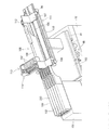
- FIGS. 13 and 14 show a fourth embodiment of the present invention. At least one of the work modules 13 is disposed in a mounter module 12 having a component supply device 22 ⁇ / b> C composed of a bulk feeder 100.
- the mounting machine module 12 can be supplied with a bulk cassette as a component supply element to the bulk feeder 100 by the supply device 15.
- the mounter module 12 is provided with a component supply device 22 ⁇ / b> C composed of a plurality of bulk feeders 100 arranged in parallel in the X-axis direction.
- the plurality of bulk feeders 100 are detachably attached to the feeder support base 101 in the Y-axis direction.
- the bulk feeder 100 is detachably provided with a bulk cassette 102 in which a large number of parts are accommodated in a bulk shape, and the parts accommodated in the bulk cassette 102 are supplied to a part supply position that can be sucked by a suction nozzle by an appropriate means. It has come to be.
- a support base 103 is installed on the moving base 91 (common base base 96) of the replenishing device 15 that automatically replenishes the bulk cassette 102 of the bulk feeder 100, and a cassette exchange unit 105 is provided on the support base 103.
- the cassette exchange unit 105 has a slider 107 that can slide in the Y-axis direction by a pair of guide rails 106, and the slider 107 is driven by a belt transmission mechanism 111 including a pair of pulleys 108 and 109 and an endless belt 110. Moved in the direction.
- the slider 107 is provided with an engaging portion 112 that is detachably engaged with the front end portion of the bulk feeder 100. By engaging the engaging portion 112 with the bulk feeder 100 to be replaced, the slider 107 has an inner portion. The bulk feeder 100 is pulled out onto the cassette exchange unit 105.
- the cassette exchange unit 105 includes a cassette storage magazine 113 that stores a plurality of bulk cassettes 102 arranged in the X-axis direction. Further, the cassette exchange unit 105 includes a cassette exchange hand 114 for exchanging the bulk cassette 102 between the bulk feeder 100 drawn on the cassette exchange unit 105 and the cassette storage magazine 113.
- the cassette exchange hand 114 grips the bulk cassette 102 to be collected in the bulk feeder 100, removes it from the bulk feeder 100, and returns it to the empty space of the cassette storage magazine 113. Thereafter, the bulk cassette 102 to be replenished is held by the cassette exchange hand 114, taken out from the cassette storage magazine 113, and set in the bulk feeder 100.
- the replenishment device 15 storing various types of bulk cassettes 102 in the cassette storage magazine 113 is transported to each mounting machine module 12 so that the setup can be automatically changed even in the production of various types of products in small quantities. Become.
- the component storage 14 that stores a plurality of component supply elements 34 and 37 having different component types, and the traveling body that can travel between the component storage 14 and the plurality of mounting machine modules 12.
- 16, 116, a movable base 91 provided on the traveling bodies 16, 116 and movable in a direction parallel to the traveling direction of the traveling bodies 16, 116, and mounted on the movable base 91, and the component supply elements 34, 37 are The component supply elements 34 and 37 are supported so as to replenish the plurality of mounting machine modules 12 and to be recovered from the plurality of mounting machine modules 12.
- the traveling bodies 16 and 116 and the moving base 91 are made common to the plurality of component supply elements 34 and 37, and a plurality of common base bases 96 on which the replenishment units 17 are respectively mounted are provided.
- the replenishment unit 17 that supports any one of at least two component supply elements of the tape feeder 34, the component tray 37, and the bulk cassette 102 that accommodates components of different component types is mounted. .
- the traveling bodies 16, 116 are supported from the component storage 14 to the mounter module 12 by supporting the component supply elements 34, 37, 102 that have caused the component break.
- necessary parts can be automatically and efficiently replenished, and labor saving and automation can be achieved.
- the operator only needs to replenish the component supply elements 34, 37, 102 necessary for the supply unit 17 in the component storage 14, and the component supply elements 34, 37 to the supply device 15 in the component storage 14. , 102 can be automated, so that the component mounting system can be continuously operated without an operator.
- the tape feeder 34, the component tray 37 or the bulk cassette 102 is mounted on the common base table 96, the tape feeder 34, the component tray 37 or the bulk cassette 102 is replenished with a small number of common base tables 96. Can be made possible.
- the replenishment unit 17 can support the plurality of component supply elements 34, 37, 102. Therefore, the replenishment unit 17 that supports the plurality of component supply elements 34, 37, 102 is used as the traveling body 16, By transporting by 116, a plurality of component supply elements 34 and 37 can be replenished in the mounting machine module 12.
- the guide rails 40a and 40b and the rack (chain) 43 parallel to the guide rails 40a and 40b are fixed to the front surfaces of the plurality of mounting machine modules 12, respectively.
- follower rollers 45 a and 45 b that engage with the guide rails 40 a and 40 b
- pinion (sprocket wheel) 47 that meshes with the rack 43
- traveling motor 48 that rotates the pinion 47.
- the common base table 96 can be transported through the pinion 47 and the rack 43 by the rotation of the traveling motor 48, and the replenishment unit 17 on the common base table 96 can be rotated according to the rotation stopping accuracy of the traveling motor 48. Can be positioned at an accurate position with respect to the mounter module 12.
- the traveling body is configured by the automatic guided vehicle 16 that is guided by the guideline 90 laid along the plurality of mounting machine modules 12 and can travel on the floor surface
- the mounting machine module By disposing the automatic guided vehicle 16 and the guideline 90 without significantly remodeling 12, it is possible to easily construct a component mounting system capable of automating component replenishment.
- a plurality of component supply elements can be held in the supply unit 17, but a single component supply element may be held in the supply unit 17. .
- the guideline 90 for magnetically guiding the automatic guided vehicle 16 may be linearly provided on the front surface of the work modules 13A and 13B.
- the plurality of replenishing devices 15 replenish components to the plurality of mounting machine modules 12 at the same time
- the plurality of replenishing devices 15 are discharged from the component storage unit 14 at the same time. It is preferable to return the plurality of replenishing devices 15 to the parts storage 14 simultaneously after the replenishment operation is completed.
- the component mounting system according to the present invention is suitable for use in replenishing components by a replenishing device that can travel between a component storage and a plurality of mounting machine modules.
Landscapes
- Engineering & Computer Science (AREA)
- Manufacturing & Machinery (AREA)
- Microelectronics & Electronic Packaging (AREA)
- Operations Research (AREA)
- Supply And Installment Of Electrical Components (AREA)
- Automatic Assembly (AREA)
Priority Applications (4)
| Application Number | Priority Date | Filing Date | Title |
|---|---|---|---|
| CN201280074688.7A CN104429174B (zh) | 2012-07-13 | 2012-07-13 | 元件安装系统 |
| EP12881079.3A EP2874481B1 (fr) | 2012-07-13 | 2012-07-13 | Système de montage de composants |
| PCT/JP2012/067981 WO2014010084A1 (fr) | 2012-07-13 | 2012-07-13 | Système de montage de composants |
| JP2014524575A JP6074425B2 (ja) | 2012-07-13 | 2012-07-13 | 部品実装システム |
Applications Claiming Priority (1)
| Application Number | Priority Date | Filing Date | Title |
|---|---|---|---|
| PCT/JP2012/067981 WO2014010084A1 (fr) | 2012-07-13 | 2012-07-13 | Système de montage de composants |
Publications (1)
| Publication Number | Publication Date |
|---|---|
| WO2014010084A1 true WO2014010084A1 (fr) | 2014-01-16 |
Family
ID=49915585
Family Applications (1)
| Application Number | Title | Priority Date | Filing Date |
|---|---|---|---|
| PCT/JP2012/067981 Ceased WO2014010084A1 (fr) | 2012-07-13 | 2012-07-13 | Système de montage de composants |
Country Status (4)
| Country | Link |
|---|---|
| EP (1) | EP2874481B1 (fr) |
| JP (1) | JP6074425B2 (fr) |
| CN (1) | CN104429174B (fr) |
| WO (1) | WO2014010084A1 (fr) |
Cited By (41)
| Publication number | Priority date | Publication date | Assignee | Title |
|---|---|---|---|---|
| WO2017033268A1 (fr) * | 2015-08-25 | 2017-03-02 | 富士機械製造株式会社 | Chaîne de montage de composants |
| CN106664820A (zh) * | 2014-09-02 | 2017-05-10 | 富士机械制造株式会社 | 元件安装系统以及元件安装方法 |
| WO2018008148A1 (fr) | 2016-07-08 | 2018-01-11 | 富士機械製造株式会社 | Système de montage de composants et dispositif de gestion |
| WO2018051498A1 (fr) * | 2016-09-16 | 2018-03-22 | ヤマハ発動機株式会社 | Système de traitement de substrat et procédé de transport de composant dans un système de traitement de substrat |
| WO2018127965A1 (fr) * | 2017-01-06 | 2018-07-12 | 株式会社Fuji | Système de commutation automatique de ligne d'alimentation de ligne d'encapsulation de composants |
| WO2018127956A1 (fr) * | 2017-01-05 | 2018-07-12 | 株式会社Fuji | Système de gestion de ligne de montage de composants |
| WO2018158856A1 (fr) * | 2017-02-28 | 2018-09-07 | 株式会社Fuji | Dispositif de réception d'énergie électrique sans contact et dispositif d'alimentation d'énergie électrique sans contact |
| WO2018173204A1 (fr) * | 2017-03-23 | 2018-09-27 | 株式会社Fuji | Système de montage et dispositif de commande d'affichage |
| WO2018179257A1 (fr) * | 2017-03-30 | 2018-10-04 | 株式会社Fuji | Système de montage et dispositif de commande de compte-rendu |
| WO2018179147A1 (fr) * | 2017-03-29 | 2018-10-04 | 株式会社Fuji | Système de montage de composant |
| JPWO2017130345A1 (ja) * | 2016-01-28 | 2018-11-15 | 株式会社Fuji | ユニット交換用台車 |
| CN109775209A (zh) * | 2017-11-13 | 2019-05-21 | Juki株式会社 | 部件管理系统 |
| CN109775211A (zh) * | 2017-11-13 | 2019-05-21 | Juki株式会社 | 部件输送装置 |
| WO2019176038A1 (fr) | 2018-03-15 | 2019-09-19 | 株式会社Fuji | Dispositif lié au montage et système de montage |
| WO2019239475A1 (fr) * | 2018-06-12 | 2019-12-19 | 株式会社Fuji | Dispositif d'échange |
| WO2019239510A1 (fr) * | 2018-06-13 | 2019-12-19 | 株式会社Fuji | Machine de travail de substrat |
| JP2020014019A (ja) * | 2019-10-09 | 2020-01-23 | 株式会社Fuji | 部品実装ライン |
| JP2020014021A (ja) * | 2019-10-09 | 2020-01-23 | 株式会社Fuji | ユニット保管庫および部品実装ライン |
| WO2020021618A1 (fr) | 2018-07-24 | 2020-01-30 | 株式会社Fuji | Dispositif de traitement d'informations, système de travail et procédé de détermination |
| JP2020113797A (ja) * | 2016-02-17 | 2020-07-27 | 株式会社Fuji | フィーダ自動交換方法 |
| JP2020119578A (ja) * | 2020-03-18 | 2020-08-06 | 株式会社Fuji | 生産ラインの安全システム制御方法 |
| CN112208987A (zh) * | 2019-07-10 | 2021-01-12 | Juki株式会社 | 部件管理系统以及部件管理方法 |
| WO2021014545A1 (fr) | 2019-07-22 | 2021-01-28 | 株式会社Fuji | Dispositif d'alimentation de pièces de plateau |
| JP2021016009A (ja) * | 2017-01-05 | 2021-02-12 | 株式会社Fuji | 部品実装システム |
| JP2021073729A (ja) * | 2021-02-03 | 2021-05-13 | 株式会社Fuji | 管理装置 |
| JP2021170680A (ja) * | 2019-10-09 | 2021-10-28 | 株式会社Fuji | 部品実装ライン |
| JP2022069563A (ja) * | 2018-06-12 | 2022-05-11 | 株式会社Fuji | 部品装着システム |
| JP2022090072A (ja) * | 2019-02-15 | 2022-06-16 | 株式会社Fuji | 部品実装システム |
| JPWO2022145442A1 (fr) * | 2020-12-28 | 2022-07-07 | ||
| CN115380638A (zh) * | 2020-04-09 | 2022-11-22 | 株式会社富士 | 生产系统 |
| WO2023007739A1 (fr) * | 2021-07-30 | 2023-02-02 | ヤマハ発動機株式会社 | Robot transporteur et système de montage de composants |
| CN115696905A (zh) * | 2021-07-26 | 2023-02-03 | 先进装配系统有限责任两合公司 | 向自动装配机供给元件的二维机械臂系统 |
| CN115696834A (zh) * | 2022-11-04 | 2023-02-03 | 深圳市东深电子股份有限公司 | 一种自动化监测巡检智能柜及其监控方法 |
| JPWO2023021577A1 (fr) * | 2021-08-17 | 2023-02-23 | ||
| US11683922B2 (en) * | 2018-08-21 | 2023-06-20 | Fuji Corporation | Component mounting system |
| US11723184B2 (en) * | 2018-06-26 | 2023-08-08 | Fuji Corporation | Component supply unit arrangement determination method and component mounting system |
| JP2024036566A (ja) * | 2021-02-03 | 2024-03-15 | 株式会社Fuji | 報知制御装置、実装システム及び実装システムの制御方法 |
| WO2024095443A1 (fr) * | 2022-11-04 | 2024-05-10 | 株式会社Fuji | Véhicule de transport autonome |
| US20240198654A1 (en) * | 2021-04-23 | 2024-06-20 | Fuji Corporation | Exchange unit and printing device |
| JP2024166168A (ja) * | 2023-05-17 | 2024-11-28 | エーエスエムピーティー・ゲーエムベーハー・ウント・コ・カーゲー | ピックアンドプレースステーションにおいてコンポーネントフィーダを交換するためのハンドリングデバイスおよびロボットシステム |
| WO2025088793A1 (fr) * | 2023-10-27 | 2025-05-01 | 株式会社Fuji | Système de production et procédé de préparation de transport |
Families Citing this family (22)
| Publication number | Priority date | Publication date | Assignee | Title |
|---|---|---|---|---|
| CN111465311B (zh) * | 2015-11-17 | 2021-02-26 | 株式会社富士 | 安装处理方法、安装系统及元件安装机 |
| JP6762968B2 (ja) | 2016-02-17 | 2020-09-30 | 株式会社Fuji | 作業装置および生産ライン |
| US10945361B2 (en) * | 2016-02-17 | 2021-03-09 | Fuji Corporation | Production line safety system |
| JP6717861B2 (ja) * | 2016-02-17 | 2020-07-08 | 株式会社Fuji | 部品実装ライン |
| JP6561317B2 (ja) * | 2016-06-01 | 2019-08-21 | パナソニックIpマネジメント株式会社 | 部品実装システム |
| EP3657282B1 (fr) * | 2017-07-20 | 2024-10-02 | Fuji Corporation | Système de travail |
| CN112292919B (zh) * | 2018-05-28 | 2021-10-08 | 株式会社富士 | 单元更换装置 |
| CN112136373B (zh) * | 2018-05-30 | 2021-10-22 | 雅马哈发动机株式会社 | 元件补给管理系统和元件安装系统 |
| DE112018007667T5 (de) * | 2018-05-30 | 2021-03-04 | Yamaha Hatsudoki Kabushiki Kaisha | Bauteilwiederauffüllungs-verwaltungssystem und bauteilmontagesystem |
| WO2019239474A1 (fr) * | 2018-06-12 | 2019-12-19 | 株式会社Fuji | Dispositif d'échange |
| CN112956287B (zh) * | 2018-12-07 | 2022-11-04 | 株式会社富士 | 对基板作业机的设备管理系统 |
| DE112019007674T5 (de) * | 2019-08-27 | 2022-06-09 | Yamaha Hatsudoki Kabushiki Kaisha | Vorrichtung zum Unterstützen der Nachfüllung von Bauelementen, Bauelementbestückungssystem und Verfahren zum Unterstützen der Nachfüllung von Bauelementen |
| WO2021106026A1 (fr) * | 2019-11-25 | 2021-06-03 | 株式会社Fuji | Système d'entrepôt |
| WO2021181538A1 (fr) * | 2020-03-10 | 2021-09-16 | 株式会社Fuji | Système de production |
| US20230422460A1 (en) * | 2020-11-26 | 2023-12-28 | Fuji Corporation | Component feeding method and management apparatus |
| DE112020007731T5 (de) * | 2020-12-25 | 2023-08-10 | Yamaha Hatsudoki Kabushiki Kaisha | Bauteillagerungssystem, Bauteillager und Magazinvorbereitungsverfahren |
| WO2022224432A1 (fr) | 2021-04-23 | 2022-10-27 | 株式会社Fuji | Système de montage |
| DE102021112830A1 (de) * | 2021-05-18 | 2022-11-24 | Asm Assembly Systems Gmbh & Co. Kg | Fertigungsstraßen-Transport |
| DE102021117281B9 (de) | 2021-07-05 | 2023-02-23 | Asm Assembly Systems Gmbh & Co. Kg | Automatisches Austauschen einer Bauelement-Zuführeinrichtung mittels eines fahrerlosen Transportfahrzeugs in Verbindung mit einer fein positionierbaren Positioniereinreichtung |
| JP7620122B2 (ja) | 2021-12-01 | 2025-01-22 | ヤマハ発動機株式会社 | 作業ロボット及び部品実装システム |
| JP2023154523A (ja) * | 2022-04-07 | 2023-10-20 | ヤマハ発動機株式会社 | 搬送ロボットの管理装置、管理方法、管理プログラム及び部品実装システム |
| WO2025115165A1 (fr) * | 2023-11-30 | 2025-06-05 | 株式会社Fuji | Dispositif de transport automatique et système de transport automatique |
Citations (7)
| Publication number | Priority date | Publication date | Assignee | Title |
|---|---|---|---|---|
| JPH01135438A (ja) * | 1987-11-16 | 1989-05-29 | Canon Inc | 物品流通システム |
| JPH03153098A (ja) * | 1989-11-10 | 1991-07-01 | Sanyo Electric Co Ltd | 部品供給システム |
| JPH0575293A (ja) * | 1991-09-12 | 1993-03-26 | Matsushita Electric Ind Co Ltd | 電子部品実装装置 |
| JP2008205009A (ja) * | 2007-02-16 | 2008-09-04 | Fuji Mach Mfg Co Ltd | 電子回路部品供給装置 |
| JP2009147197A (ja) | 2007-12-17 | 2009-07-02 | Fuji Mach Mfg Co Ltd | トレイ部品供給装置 |
| JP2012043886A (ja) | 2010-08-17 | 2012-03-01 | Fuji Mach Mfg Co Ltd | 部品照合方法および装置 |
| JP2012104635A (ja) | 2010-11-10 | 2012-05-31 | Fuji Mach Mfg Co Ltd | スプライシング誤作業防止方法 |
Family Cites Families (2)
| Publication number | Priority date | Publication date | Assignee | Title |
|---|---|---|---|---|
| US5193268A (en) * | 1989-11-07 | 1993-03-16 | Sanyo Electric Co., Ltd. | Parts feeding system utilizing an unmanned conveying machine |
| JPH0597247A (ja) * | 1991-10-02 | 1993-04-20 | Nippon Hodo Co Ltd | 材料移載システム |
-
2012
- 2012-07-13 JP JP2014524575A patent/JP6074425B2/ja active Active
- 2012-07-13 EP EP12881079.3A patent/EP2874481B1/fr active Active
- 2012-07-13 WO PCT/JP2012/067981 patent/WO2014010084A1/fr not_active Ceased
- 2012-07-13 CN CN201280074688.7A patent/CN104429174B/zh active Active
Patent Citations (7)
| Publication number | Priority date | Publication date | Assignee | Title |
|---|---|---|---|---|
| JPH01135438A (ja) * | 1987-11-16 | 1989-05-29 | Canon Inc | 物品流通システム |
| JPH03153098A (ja) * | 1989-11-10 | 1991-07-01 | Sanyo Electric Co Ltd | 部品供給システム |
| JPH0575293A (ja) * | 1991-09-12 | 1993-03-26 | Matsushita Electric Ind Co Ltd | 電子部品実装装置 |
| JP2008205009A (ja) * | 2007-02-16 | 2008-09-04 | Fuji Mach Mfg Co Ltd | 電子回路部品供給装置 |
| JP2009147197A (ja) | 2007-12-17 | 2009-07-02 | Fuji Mach Mfg Co Ltd | トレイ部品供給装置 |
| JP2012043886A (ja) | 2010-08-17 | 2012-03-01 | Fuji Mach Mfg Co Ltd | 部品照合方法および装置 |
| JP2012104635A (ja) | 2010-11-10 | 2012-05-31 | Fuji Mach Mfg Co Ltd | スプライシング誤作業防止方法 |
Non-Patent Citations (1)
| Title |
|---|
| See also references of EP2874481A4 |
Cited By (105)
| Publication number | Priority date | Publication date | Assignee | Title |
|---|---|---|---|---|
| CN106664820B (zh) * | 2014-09-02 | 2019-04-19 | 株式会社富士 | 元件安装系统以及元件安装方法 |
| CN106664820A (zh) * | 2014-09-02 | 2017-05-10 | 富士机械制造株式会社 | 元件安装系统以及元件安装方法 |
| EP3190864A4 (fr) * | 2014-09-02 | 2017-08-30 | Fuji Machine Mfg. Co., Ltd. | Système de montage de composant et procédé de montage de composant |
| US10561050B2 (en) | 2014-09-02 | 2020-02-11 | Fuji Corporation | Component mounting system and component mounting method |
| EP4138535A1 (fr) * | 2015-08-25 | 2023-02-22 | FUJI Corporation | Ligne de montage de composants |
| WO2017033268A1 (fr) * | 2015-08-25 | 2017-03-02 | 富士機械製造株式会社 | Chaîne de montage de composants |
| US10820459B2 (en) | 2015-08-25 | 2020-10-27 | Fuji Corporation | Component mounting line |
| JPWO2017033268A1 (ja) * | 2015-08-25 | 2018-06-14 | 株式会社Fuji | 部品実装ライン |
| US11240949B2 (en) | 2015-08-25 | 2022-02-01 | Fuji Corporation | Component mounting line |
| EP3344027B1 (fr) * | 2015-08-25 | 2022-12-14 | FUJI Corporation | Chaîne de montage de composants |
| JP2021114632A (ja) * | 2016-01-28 | 2021-08-05 | 株式会社Fuji | ユニット交換用台車 |
| JPWO2017130345A1 (ja) * | 2016-01-28 | 2018-11-15 | 株式会社Fuji | ユニット交換用台車 |
| JP7073560B2 (ja) | 2016-01-28 | 2022-05-23 | 株式会社Fuji | ユニット交換用台車およびそのセット方法 |
| JP2020113797A (ja) * | 2016-02-17 | 2020-07-27 | 株式会社Fuji | フィーダ自動交換方法 |
| US11470751B2 (en) | 2016-07-08 | 2022-10-11 | Fuji Corporation | Component-mounting system and management device |
| EP3780929A1 (fr) | 2016-07-08 | 2021-02-17 | Fuji Corporation | Système de montage de composants et dispositif de gestion |
| WO2018008148A1 (fr) | 2016-07-08 | 2018-01-11 | 富士機械製造株式会社 | Système de montage de composants et dispositif de gestion |
| JPWO2018051498A1 (ja) * | 2016-09-16 | 2019-04-11 | ヤマハ発動機株式会社 | 基板作業システム、および、基板作業システムにおける部品搬送方法 |
| WO2018051498A1 (fr) * | 2016-09-16 | 2018-03-22 | ヤマハ発動機株式会社 | Système de traitement de substrat et procédé de transport de composant dans un système de traitement de substrat |
| US11912412B2 (en) | 2016-09-16 | 2024-02-27 | Yamaha Hatsudoki Kabushiki Kaisha | Substrate working system and method for conveying component in substrate working system |
| JP7804032B2 (ja) | 2017-01-05 | 2026-01-21 | 株式会社Fuji | 部品実装システム |
| JP2021016009A (ja) * | 2017-01-05 | 2021-02-12 | 株式会社Fuji | 部品実装システム |
| WO2018127956A1 (fr) * | 2017-01-05 | 2018-07-12 | 株式会社Fuji | Système de gestion de ligne de montage de composants |
| US11134601B2 (en) | 2017-01-05 | 2021-09-28 | Fuji Corporation | System for managing component mounting line |
| JP7313326B2 (ja) | 2017-01-05 | 2023-07-24 | 株式会社Fuji | 部品実装システム |
| JP2023126378A (ja) * | 2017-01-05 | 2023-09-07 | 株式会社Fuji | 部品実装システム |
| JP7574366B2 (ja) | 2017-01-05 | 2024-10-28 | 株式会社Fuji | 部品実装システム |
| JPWO2018127956A1 (ja) * | 2017-01-05 | 2019-07-25 | 株式会社Fuji | 部品実装ラインの管理システム |
| JP2025003485A (ja) * | 2017-01-05 | 2025-01-09 | 株式会社Fuji | 部品実装システム |
| JP2025003484A (ja) * | 2017-01-05 | 2025-01-09 | 株式会社Fuji | 部品実装システム |
| JPWO2018127965A1 (ja) * | 2017-01-06 | 2019-07-25 | 株式会社Fuji | 部品実装ラインのフィーダ自動交換システム |
| WO2018127965A1 (fr) * | 2017-01-06 | 2018-07-12 | 株式会社Fuji | Système de commutation automatique de ligne d'alimentation de ligne d'encapsulation de composants |
| JPWO2018158856A1 (ja) * | 2017-02-28 | 2019-11-21 | 株式会社Fuji | 非接触受電装置および非接触給電システム |
| WO2018158856A1 (fr) * | 2017-02-28 | 2018-09-07 | 株式会社Fuji | Dispositif de réception d'énergie électrique sans contact et dispositif d'alimentation d'énergie électrique sans contact |
| JPWO2018173204A1 (ja) * | 2017-03-23 | 2019-11-21 | 株式会社Fuji | 実装システム及び表示制御装置 |
| WO2018173204A1 (fr) * | 2017-03-23 | 2018-09-27 | 株式会社Fuji | Système de montage et dispositif de commande d'affichage |
| WO2018179147A1 (fr) * | 2017-03-29 | 2018-10-04 | 株式会社Fuji | Système de montage de composant |
| JPWO2018179147A1 (ja) * | 2017-03-29 | 2019-11-21 | 株式会社Fuji | 部品実装システム |
| US11212951B2 (en) | 2017-03-29 | 2021-12-28 | Fuji Corporation | Component mounting system |
| US11449043B2 (en) | 2017-03-30 | 2022-09-20 | Fuji Corporation | Mounting system and reporting control device |
| WO2018179257A1 (fr) * | 2017-03-30 | 2018-10-04 | 株式会社Fuji | Système de montage et dispositif de commande de compte-rendu |
| JPWO2018179257A1 (ja) * | 2017-03-30 | 2019-12-12 | 株式会社Fuji | 実装システム及び報知制御装置 |
| JP2019091771A (ja) * | 2017-11-13 | 2019-06-13 | Juki株式会社 | 部品管理システム |
| CN109775209B (zh) * | 2017-11-13 | 2021-10-22 | Juki株式会社 | 部件管理系统 |
| CN109775211B (zh) * | 2017-11-13 | 2021-05-07 | Juki株式会社 | 部件输送装置 |
| CN109775211A (zh) * | 2017-11-13 | 2019-05-21 | Juki株式会社 | 部件输送装置 |
| CN109775209A (zh) * | 2017-11-13 | 2019-05-21 | Juki株式会社 | 部件管理系统 |
| WO2019176038A1 (fr) | 2018-03-15 | 2019-09-19 | 株式会社Fuji | Dispositif lié au montage et système de montage |
| US11457551B2 (en) | 2018-03-15 | 2022-09-27 | Fuji Corporation | Mounting-related device and mounting system |
| JP7229405B2 (ja) | 2018-06-12 | 2023-02-27 | 株式会社Fuji | 部品装着システム |
| WO2019239475A1 (fr) * | 2018-06-12 | 2019-12-19 | 株式会社Fuji | Dispositif d'échange |
| JPWO2019239475A1 (ja) * | 2018-06-12 | 2021-04-01 | 株式会社Fuji | 交換装置 |
| JP7042908B2 (ja) | 2018-06-12 | 2022-03-28 | 株式会社Fuji | 交換装置 |
| JP2022069563A (ja) * | 2018-06-12 | 2022-05-11 | 株式会社Fuji | 部品装着システム |
| WO2019239510A1 (fr) * | 2018-06-13 | 2019-12-19 | 株式会社Fuji | Machine de travail de substrat |
| JP7035184B2 (ja) | 2018-06-13 | 2022-03-14 | 株式会社Fuji | 対基板作業機 |
| JPWO2019239510A1 (ja) * | 2018-06-13 | 2021-02-12 | 株式会社Fuji | 対基板作業機 |
| US11723184B2 (en) * | 2018-06-26 | 2023-08-08 | Fuji Corporation | Component supply unit arrangement determination method and component mounting system |
| WO2020021618A1 (fr) | 2018-07-24 | 2020-01-30 | 株式会社Fuji | Dispositif de traitement d'informations, système de travail et procédé de détermination |
| US11683922B2 (en) * | 2018-08-21 | 2023-06-20 | Fuji Corporation | Component mounting system |
| JP2022090072A (ja) * | 2019-02-15 | 2022-06-16 | 株式会社Fuji | 部品実装システム |
| JP7351964B2 (ja) | 2019-02-15 | 2023-09-27 | 株式会社Fuji | 部品実装システム |
| CN112208987A (zh) * | 2019-07-10 | 2021-01-12 | Juki株式会社 | 部件管理系统以及部件管理方法 |
| CN112208987B (zh) * | 2019-07-10 | 2024-01-30 | Juki株式会社 | 部件管理系统以及部件管理方法 |
| WO2021014545A1 (fr) | 2019-07-22 | 2021-01-28 | 株式会社Fuji | Dispositif d'alimentation de pièces de plateau |
| US12022620B2 (en) | 2019-07-22 | 2024-06-25 | Fuji Corporation | Tray parts feeder |
| JP2023001272A (ja) * | 2019-10-09 | 2023-01-04 | 株式会社Fuji | 部品実装ラインおよび部品供給方法 |
| JP2024166360A (ja) * | 2019-10-09 | 2024-11-28 | 株式会社Fuji | 部品実装ライン |
| JP7728942B2 (ja) | 2019-10-09 | 2025-08-25 | 株式会社Fuji | 部品実装ライン |
| JP2021170680A (ja) * | 2019-10-09 | 2021-10-28 | 株式会社Fuji | 部品実装ライン |
| JP2024036630A (ja) * | 2019-10-09 | 2024-03-15 | 株式会社Fuji | 部品実装ラインおよび部品供給方法 |
| JP7618861B2 (ja) | 2019-10-09 | 2025-01-21 | 株式会社Fuji | 部品実装ラインおよび部品供給方法 |
| JP7436609B2 (ja) | 2019-10-09 | 2024-02-21 | 株式会社Fuji | 部品実装ラインおよび部品供給方法 |
| JP7176063B2 (ja) | 2019-10-09 | 2022-11-21 | 株式会社Fuji | 部品実装ライン |
| JP2020014019A (ja) * | 2019-10-09 | 2020-01-23 | 株式会社Fuji | 部品実装ライン |
| JP2020014021A (ja) * | 2019-10-09 | 2020-01-23 | 株式会社Fuji | ユニット保管庫および部品実装ライン |
| JP2020119578A (ja) * | 2020-03-18 | 2020-08-06 | 株式会社Fuji | 生産ラインの安全システム制御方法 |
| CN115380638A (zh) * | 2020-04-09 | 2022-11-22 | 株式会社富士 | 生产系统 |
| JP7173712B2 (ja) | 2020-04-16 | 2022-11-16 | 株式会社Fuji | 自動交換装置及び自動交換システム |
| JP2021184467A (ja) * | 2020-04-16 | 2021-12-02 | 株式会社Fuji | 自動交換装置及び自動交換システム |
| JP7847342B2 (ja) | 2020-12-28 | 2026-04-17 | パナソニックIpマネジメント株式会社 | 部品ストック装置および部品装着システム |
| JPWO2022145442A1 (fr) * | 2020-12-28 | 2022-07-07 | ||
| WO2022145442A1 (fr) * | 2020-12-28 | 2022-07-07 | パナソニックIpマネジメント株式会社 | Dispositif de stockage de composant et système de montage de composant |
| JP7241788B2 (ja) | 2021-02-03 | 2023-03-17 | 株式会社Fuji | 管理装置 |
| JP2021073729A (ja) * | 2021-02-03 | 2021-05-13 | 株式会社Fuji | 管理装置 |
| JP2024036566A (ja) * | 2021-02-03 | 2024-03-15 | 株式会社Fuji | 報知制御装置、実装システム及び実装システムの制御方法 |
| JP7707333B2 (ja) | 2021-02-03 | 2025-07-14 | 株式会社Fuji | 報知制御装置、実装システム及び実装システムの制御方法 |
| US12427762B2 (en) * | 2021-04-23 | 2025-09-30 | Fuji Corporation | Exchange unit and printing device |
| US20240198654A1 (en) * | 2021-04-23 | 2024-06-20 | Fuji Corporation | Exchange unit and printing device |
| JP2023017728A (ja) * | 2021-07-26 | 2023-02-07 | エーエスエム・アセンブリー・システムズ・ゲーエムベーハー・ウント・コ・カーゲー | 実装機械にアセンブリ部品を供給するための2次元ロボットシステム |
| JP7311687B2 (ja) | 2021-07-26 | 2023-07-19 | エーエスエムピーティー・ゲーエムベーハー・ウント・コ・カーゲー | 実装機械にアセンブリ部品を供給するための2次元ロボットシステム |
| CN115696905A (zh) * | 2021-07-26 | 2023-02-03 | 先进装配系统有限责任两合公司 | 向自动装配机供给元件的二维机械臂系统 |
| CN117546621A (zh) * | 2021-07-30 | 2024-02-09 | 雅马哈发动机株式会社 | 运送机器人及部件安装系统 |
| JP7518979B2 (ja) | 2021-07-30 | 2024-07-18 | ヤマハ発動機株式会社 | 搬送ロボットおよび部品実装システム |
| JPWO2023007739A1 (fr) * | 2021-07-30 | 2023-02-02 | ||
| WO2023007739A1 (fr) * | 2021-07-30 | 2023-02-02 | ヤマハ発動機株式会社 | Robot transporteur et système de montage de composants |
| CN117501820A (zh) * | 2021-08-17 | 2024-02-02 | 株式会社富士 | 料仓收纳装置 |
| WO2023021577A1 (fr) * | 2021-08-17 | 2023-02-23 | 株式会社Fuji | Dispositif de stockage de magasin |
| JPWO2023021577A1 (fr) * | 2021-08-17 | 2023-02-23 | ||
| US20240343487A1 (en) * | 2021-08-17 | 2024-10-17 | Fuji Corporation | Magazine storage device |
| JP7806059B2 (ja) | 2021-08-17 | 2026-01-26 | 株式会社Fuji | マガジン収納装置 |
| WO2024095443A1 (fr) * | 2022-11-04 | 2024-05-10 | 株式会社Fuji | Véhicule de transport autonome |
| CN115696834A (zh) * | 2022-11-04 | 2023-02-03 | 深圳市东深电子股份有限公司 | 一种自动化监测巡检智能柜及其监控方法 |
| JP2024166168A (ja) * | 2023-05-17 | 2024-11-28 | エーエスエムピーティー・ゲーエムベーハー・ウント・コ・カーゲー | ピックアンドプレースステーションにおいてコンポーネントフィーダを交換するためのハンドリングデバイスおよびロボットシステム |
| WO2025088793A1 (fr) * | 2023-10-27 | 2025-05-01 | 株式会社Fuji | Système de production et procédé de préparation de transport |
Also Published As
| Publication number | Publication date |
|---|---|
| CN104429174B (zh) | 2017-03-08 |
| EP2874481A1 (fr) | 2015-05-20 |
| CN104429174A (zh) | 2015-03-18 |
| EP2874481A4 (fr) | 2015-11-25 |
| JPWO2014010084A1 (ja) | 2016-06-20 |
| EP2874481B1 (fr) | 2023-01-25 |
| JP6074425B2 (ja) | 2017-02-01 |
Similar Documents
| Publication | Publication Date | Title |
|---|---|---|
| JP6074425B2 (ja) | 部品実装システム | |
| JP5963863B2 (ja) | 部品実装システム | |
| JP5767754B2 (ja) | 基板作業機用の認識装置 | |
| CN112042285B (zh) | 自动更换系统、管理装置以及自动更换方法 | |
| JPWO2001026440A1 (ja) | 板状部材の搬送保持装置及びその方法 | |
| KR101126501B1 (ko) | 전자 부품 장착 장치 | |
| WO2016035145A1 (fr) | Système de montage de composant et procédé de montage de composant | |
| JPWO2004066701A1 (ja) | 対回路基板作業機およびそれに対する構成要素の供給方法 | |
| JP6684015B2 (ja) | 部品実装システム及び部品実装方法 | |
| CN115582680A (zh) | 利用无人驾驶输送工具结合可精细定位的定位装置自动置换元件供给装置 | |
| US12022620B2 (en) | Tray parts feeder | |
| CN103857270A (zh) | 电子元件的安装方法以及表面安装机 | |
| CN117546621A (zh) | 运送机器人及部件安装系统 | |
| JP6120516B2 (ja) | 部品補給システム | |
| JP5808160B2 (ja) | 電子部品実装装置 | |
| JPWO2004093514A1 (ja) | 基板搬送方法および装置 | |
| CN112772012A (zh) | 安装基板制造系统、部件安装系统以及收纳体移送方法 | |
| KR20160029118A (ko) | 부품 실장 장치, 부품 실장 방법 | |
| WO2023105794A1 (fr) | Robot de transport et système de montage de composants | |
| JP5473465B2 (ja) | 電子部品の実装装置 | |
| JPWO2019163044A1 (ja) | 部品実装システム | |
| JP6230609B2 (ja) | 自動組立装置用部品供給装置 | |
| JP5618749B2 (ja) | Led部品を分別廃棄する部品実装システム | |
| CN1326438C (zh) | 安装机及安装方法 | |
| JP4667113B2 (ja) | 電子部品装着装置 |
Legal Events
| Date | Code | Title | Description |
|---|---|---|---|
| 121 | Ep: the epo has been informed by wipo that ep was designated in this application |
Ref document number: 12881079 Country of ref document: EP Kind code of ref document: A1 |
|
| ENP | Entry into the national phase |
Ref document number: 2014524575 Country of ref document: JP Kind code of ref document: A |
|
| WWE | Wipo information: entry into national phase |
Ref document number: 2012881079 Country of ref document: EP |
|
| NENP | Non-entry into the national phase |
Ref country code: DE |