WO2014010103A1 - Actionneur électrique - Google Patents
Actionneur électrique Download PDFInfo
- Publication number
- WO2014010103A1 WO2014010103A1 PCT/JP2012/069904 JP2012069904W WO2014010103A1 WO 2014010103 A1 WO2014010103 A1 WO 2014010103A1 JP 2012069904 W JP2012069904 W JP 2012069904W WO 2014010103 A1 WO2014010103 A1 WO 2014010103A1
- Authority
- WO
- WIPO (PCT)
- Prior art keywords
- rotor
- electric actuator
- operation member
- screw shaft
- load
- Prior art date
- Legal status (The legal status is an assumption and is not a legal conclusion. Google has not performed a legal analysis and makes no representation as to the accuracy of the status listed.)
- Ceased
Links
Images


Classifications
-
- H—ELECTRICITY
- H02—GENERATION; CONVERSION OR DISTRIBUTION OF ELECTRIC POWER
- H02K—DYNAMO-ELECTRIC MACHINES
- H02K7/00—Arrangements for handling mechanical energy structurally associated with dynamo-electric machines, e.g. structural association with mechanical driving motors or auxiliary dynamo-electric machines
- H02K7/06—Means for converting reciprocating motion into rotary motion or vice versa
-
- F—MECHANICAL ENGINEERING; LIGHTING; HEATING; WEAPONS; BLASTING
- F16—ENGINEERING ELEMENTS AND UNITS; GENERAL MEASURES FOR PRODUCING AND MAINTAINING EFFECTIVE FUNCTIONING OF MACHINES OR INSTALLATIONS; THERMAL INSULATION IN GENERAL
- F16D—COUPLINGS FOR TRANSMITTING ROTATION; CLUTCHES; BRAKES
- F16D23/00—Details of mechanically-actuated clutches not specific for one distinct type
- F16D23/12—Mechanical clutch-actuating mechanisms arranged outside the clutch as such
- F16D23/14—Clutch-actuating sleeves or bearings; Actuating members directly connected to clutch-actuating sleeves or bearings
-
- F—MECHANICAL ENGINEERING; LIGHTING; HEATING; WEAPONS; BLASTING
- F16—ENGINEERING ELEMENTS AND UNITS; GENERAL MEASURES FOR PRODUCING AND MAINTAINING EFFECTIVE FUNCTIONING OF MACHINES OR INSTALLATIONS; THERMAL INSULATION IN GENERAL
- F16D—COUPLINGS FOR TRANSMITTING ROTATION; CLUTCHES; BRAKES
- F16D28/00—Electrically-actuated clutches
-
- F—MECHANICAL ENGINEERING; LIGHTING; HEATING; WEAPONS; BLASTING
- F16—ENGINEERING ELEMENTS AND UNITS; GENERAL MEASURES FOR PRODUCING AND MAINTAINING EFFECTIVE FUNCTIONING OF MACHINES OR INSTALLATIONS; THERMAL INSULATION IN GENERAL
- F16H—GEARING
- F16H25/00—Gearings comprising primarily only cams, cam-followers and screw-and-nut mechanisms
- F16H25/18—Gearings comprising primarily only cams, cam-followers and screw-and-nut mechanisms for conveying or interconverting oscillating or reciprocating motions
- F16H25/20—Screw mechanisms
- F16H25/22—Screw mechanisms with balls, rollers, or similar members between the co-operating parts; Elements essential to the use of such members
- F16H25/2204—Screw mechanisms with balls, rollers, or similar members between the co-operating parts; Elements essential to the use of such members with balls
-
- F—MECHANICAL ENGINEERING; LIGHTING; HEATING; WEAPONS; BLASTING
- F16—ENGINEERING ELEMENTS AND UNITS; GENERAL MEASURES FOR PRODUCING AND MAINTAINING EFFECTIVE FUNCTIONING OF MACHINES OR INSTALLATIONS; THERMAL INSULATION IN GENERAL
- F16H—GEARING
- F16H63/00—Control outputs from the control unit to change-speed- or reversing-gearings for conveying rotary motion or to other devices than the final output mechanism
- F16H63/02—Final output mechanisms therefor; Actuating means for the final output mechanisms
- F16H63/30—Constructional features of the final output mechanisms
- F16H63/34—Locking or disabling mechanisms
- F16H63/3416—Parking lock mechanisms or brakes in the transmission
- F16H63/3458—Parking lock mechanisms or brakes in the transmission with electric actuating means, e.g. shift by wire
- F16H63/3466—Parking lock mechanisms or brakes in the transmission with electric actuating means, e.g. shift by wire using electric motors
-
- H—ELECTRICITY
- H02—GENERATION; CONVERSION OR DISTRIBUTION OF ELECTRIC POWER
- H02K—DYNAMO-ELECTRIC MACHINES
- H02K11/00—Structural association of dynamo-electric machines with electric components or with devices for shielding, monitoring or protection
- H02K11/20—Structural association of dynamo-electric machines with electric components or with devices for shielding, monitoring or protection for measuring, monitoring, testing, protecting or switching
- H02K11/24—Devices for sensing torque, or actuated thereby
-
- H—ELECTRICITY
- H02—GENERATION; CONVERSION OR DISTRIBUTION OF ELECTRIC POWER
- H02K—DYNAMO-ELECTRIC MACHINES
- H02K7/00—Arrangements for handling mechanical energy structurally associated with dynamo-electric machines, e.g. structural association with mechanical driving motors or auxiliary dynamo-electric machines
- H02K7/08—Structural association with bearings
- H02K7/085—Structural association with bearings radially supporting the rotary shaft at only one end of the rotor
-
- H—ELECTRICITY
- H02—GENERATION; CONVERSION OR DISTRIBUTION OF ELECTRIC POWER
- H02K—DYNAMO-ELECTRIC MACHINES
- H02K7/00—Arrangements for handling mechanical energy structurally associated with dynamo-electric machines, e.g. structural association with mechanical driving motors or auxiliary dynamo-electric machines
- H02K7/10—Structural association with clutches, brakes, gears, pulleys or mechanical starters
- H02K7/108—Structural association with clutches, brakes, gears, pulleys or mechanical starters with friction clutches
-
- F—MECHANICAL ENGINEERING; LIGHTING; HEATING; WEAPONS; BLASTING
- F16—ENGINEERING ELEMENTS AND UNITS; GENERAL MEASURES FOR PRODUCING AND MAINTAINING EFFECTIVE FUNCTIONING OF MACHINES OR INSTALLATIONS; THERMAL INSULATION IN GENERAL
- F16D—COUPLINGS FOR TRANSMITTING ROTATION; CLUTCHES; BRAKES
- F16D23/00—Details of mechanically-actuated clutches not specific for one distinct type
- F16D23/12—Mechanical clutch-actuating mechanisms arranged outside the clutch as such
- F16D2023/123—Clutch actuation by cams, ramps or ball-screw mechanisms
-
- F—MECHANICAL ENGINEERING; LIGHTING; HEATING; WEAPONS; BLASTING
- F16—ENGINEERING ELEMENTS AND UNITS; GENERAL MEASURES FOR PRODUCING AND MAINTAINING EFFECTIVE FUNCTIONING OF MACHINES OR INSTALLATIONS; THERMAL INSULATION IN GENERAL
- F16H—GEARING
- F16H25/00—Gearings comprising primarily only cams, cam-followers and screw-and-nut mechanisms
- F16H25/18—Gearings comprising primarily only cams, cam-followers and screw-and-nut mechanisms for conveying or interconverting oscillating or reciprocating motions
- F16H25/20—Screw mechanisms
- F16H2025/2062—Arrangements for driving the actuator
- F16H2025/2075—Coaxial drive motors
- F16H2025/2078—Coaxial drive motors the rotor being integrated with the nut or screw body
-
- F—MECHANICAL ENGINEERING; LIGHTING; HEATING; WEAPONS; BLASTING
- F16—ENGINEERING ELEMENTS AND UNITS; GENERAL MEASURES FOR PRODUCING AND MAINTAINING EFFECTIVE FUNCTIONING OF MACHINES OR INSTALLATIONS; THERMAL INSULATION IN GENERAL
- F16H—GEARING
- F16H2200/00—Transmissions for multiple ratios
- F16H2200/003—Transmissions for multiple ratios characterised by the number of forward speeds
- F16H2200/0047—Transmissions for multiple ratios characterised by the number of forward speeds the gear ratios comprising five forward speeds
-
- F—MECHANICAL ENGINEERING; LIGHTING; HEATING; WEAPONS; BLASTING
- F16—ENGINEERING ELEMENTS AND UNITS; GENERAL MEASURES FOR PRODUCING AND MAINTAINING EFFECTIVE FUNCTIONING OF MACHINES OR INSTALLATIONS; THERMAL INSULATION IN GENERAL
- F16H—GEARING
- F16H3/00—Toothed gearings for conveying rotary motion with variable gear ratio or for reversing rotary motion
- F16H3/02—Toothed gearings for conveying rotary motion with variable gear ratio or for reversing rotary motion without gears having orbital motion
- F16H3/08—Toothed gearings for conveying rotary motion with variable gear ratio or for reversing rotary motion without gears having orbital motion exclusively or essentially with continuously meshing gears, that can be disengaged from their shafts
- F16H3/087—Toothed gearings for conveying rotary motion with variable gear ratio or for reversing rotary motion without gears having orbital motion exclusively or essentially with continuously meshing gears, that can be disengaged from their shafts characterised by the disposition of the gears
- F16H3/089—Toothed gearings for conveying rotary motion with variable gear ratio or for reversing rotary motion without gears having orbital motion exclusively or essentially with continuously meshing gears, that can be disengaged from their shafts characterised by the disposition of the gears all of the meshing gears being supported by a pair of parallel shafts, one being the input shaft and the other the output shaft, there being no countershaft involved
Definitions
- the present invention relates to an electric actuator having a mechanism for converting a rotary motion of a motor into a linear motion.
- the number of parts is as small as possible in order to reduce the mass as much as possible and reduce the cost as much as possible.
- the object of the present invention is to reduce the number of parts of the electric actuator.
- the present invention is a rod-shaped member, an operation member having a spiral first groove on the outer peripheral surface on one end side, and a cylindrical member having a hollow portion in which the operation member is disposed, A rotor having a spiral second groove corresponding to the first groove on a part of the inner peripheral surface of the hollow portion, and an opening on the other end side of the operating member protruding from the hollow portion; A plurality of balls disposed between the first groove and the second groove; a circulation member attached to the rotor for circulating the balls; and the rotor disposed on a radially outer side of the rotor.
- Rotation suppression that suppresses rotation of the operation member around the axis by engaging with a part of the operation member and a stator that moves the operation member in the axial direction by rotating the rotor around the axis A member, It is a non-electric actuator.
- This electric actuator integrates a ball screw nut and a motor rotor so that the motor rotor functions as a ball screw nut. For this reason, the number of parts for advancing and retracting the operation member can be reduced, and the structure can be simplified. Further, since this electric actuator associates the operation member with the rotation suppressing member to suppress the rotation of the operation member, no member such as a key is required. As a result, this electric actuator can reduce the number of parts.
- the circulating member is embedded in the rotor from the outer peripheral surface of the rotor, and the rotor includes a cylindrical member attached to the outer peripheral surface of the rotor and the outer side of the circulating member.
- the rotor includes a cylindrical member attached to the outer peripheral surface of the rotor and the outer side of the circulating member.
- the portion of the operating member where the first groove is formed and the portion of the rotor where the second groove is formed preferably have the same load direction in the axial direction.
- the operating member has a cylindrical screw shaft having the first groove on the outer peripheral surface attached to the outer peripheral portion on the one end side, and the screw shaft is connected to the operating member.
- the rotor is attached to one end side, and the rotor side is rotatably supported by a casing to which the stator is attached via a rolling bearing, and the plurality of balls are arranged in the axial direction.
- the input position of the load to the screw shaft is disposed at a position farther from the rolling bearing than the central portion of the region.
- the input position of the load to the screw shaft is a position farther from the rolling bearing than the region where the plurality of balls are arranged in the axial direction. Preferably they are arranged.
- this electric actuator can make the surface pressure of a ball contact point more uniform according to the position in an axial direction.
- the operating member has a cylindrical screw shaft having the first groove on the outer peripheral surface attached to the outer peripheral portion on the one end side, and the screw shaft is connected to the operating member.
- the rotor is attached to one end side, and the rotor has a side opposite to the opening that is rotatably supported by a casing to which the stator is attached via a rolling bearing, and in the axial direction, the plurality of balls It is preferable that the input position of the load to the screw shaft is disposed at a position farther from the rolling bearing than the central portion of the region where the shaft is disposed.
- the direction of the load in an axial direction can be made the same in the part in which the 1st slot of the operation member is formed, and the part in which the 2nd slot of the rotor is formed.
- this electric actuator can make the surface pressure of the ball contact point uniform according to the position in the axial direction.
- the input position of the load to the screw shaft is a position farther from the rolling bearing than the region where the plurality of balls are arranged in the axial direction. Preferably they are arranged.
- this electric actuator can make the surface pressure of a ball contact point more uniform according to the position in an axial direction.
- the rolling bearing has a sealing member for sealing between the inner ring and the outer ring on the side where the rotor and the stator are disposed.
- the opening side of the rotor is preferably an inner ring of the rolling bearing.
- the operation member has a passage extending in a longitudinal direction of the operation member and opening at an end portion on the rotor side, and the signal line of the torque sensor is connected to the passage of the operation member. It is preferable to draw out through the opening and to be fixed to the operating member at the opening. By doing so, the relative movement of the opening and the passage and the signal line is restricted, so that it is possible to suppress a decrease in durability due to rubbing of the signal line and the like.
- the inner surface of the power transmission shaft is preferably covered with a Ni-based thin film.
- the present invention operates a clutch of a power transmission device having a hollow power transmission shaft for transmitting power from a power source and a clutch disposed between the power source and the power transmission shaft, and a stator. And a rotor disposed on the radially inner side of the stator, a rod-shaped operation member disposed on the inner side of the power transmission shaft, and the rotational motion of the rotor converted into a linear motion in the extending direction of the operation member And a clutch release bearing attached to the end of the operation member on the opposite side of the conversion mechanism to give input from the operation member to the clutch, and the power transmission attached to the operation member
- An electric actuator including a torque sensor that detects torque transmitted by a shaft.
- This electric actuator has a unit structure in which an electric motor including a clutch release bearing, a torque sensor, a stator and a rotor is integrated through an operation member.
- the operation member has a passage extending in a longitudinal direction of the operation member and opening at an end portion on the conversion mechanism side, and the signal line of the torque sensor is connected to the passage of the operation member. It is preferable to be pulled out from the opening through the opening and fixed to the operation member at the opening. By doing so, the relative movement of the opening and the passage and the signal line is restricted, so that it is possible to suppress a decrease in durability due to rubbing of the signal line and the like.
- the torque sensor includes a first torque sensor, and a second torque sensor attached to the first torque sensor at different positions in the longitudinal direction and the circumferential direction of the operation member. Is preferred. By doing in this way, the error by the rotation fluctuation of a power transmission shaft can be corrected.
- the inner surface of the power transmission shaft is preferably covered with a Ni-based thin film.
- the torque sensor is attached to an outer peripheral portion of the operation member and detects the torque from the inside of the power transmission shaft.
- the torque sensor is less susceptible to the influence of lubricating oil or the like present in the power transmission device, so that durability and reliability are improved.
- a resin is interposed between the torque sensor and the operation member.
- the operation member is preferably non-magnetic.
- a magnetic fluid exists between the operation member and the power transmission shaft.
- the present invention can reduce the number of parts of the electric actuator.
- FIG. 1 is a skeleton diagram showing an example of an automatic transmission device including an electric actuator according to the present embodiment.
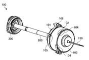
- FIG. 2 is a perspective view showing the electric actuator according to the present embodiment.
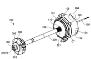
- FIG. 3 is a perspective view showing the electric actuator according to the present embodiment.
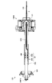
- FIG. 4 is a cross-sectional view of the electric actuator according to the present embodiment.
- FIG. 5 is an exploded perspective view of the electric motor included in the electric actuator according to the present embodiment.
- FIG. 6 is a cross-sectional view showing the electric actuator according to the present embodiment in a state where the clutch release bearing is attached to the pull rod.
- FIG. 7 is a perspective view showing an example of the arrangement of the torque sensors.
- FIG. 8 is an enlarged cross-sectional view of a portion where the torque sensor is attached.
- FIG. 1 is a skeleton diagram showing an example of an automatic transmission device including an electric actuator according to the present embodiment.
- FIG. 2 is a perspective view showing the electric actuator according to the present embodiment.
- FIG. 9 is a schematic diagram showing a relationship of force between a screw shaft and a rotor included in the electric actuator.
- FIG. 10 is a schematic diagram illustrating a relationship of force between a screw shaft and a rotor included in the electric actuator.
- FIG. 11 is a diagram showing a distribution of surface pressure acting on a ball included in the electric actuator according to the present embodiment.
- FIG. 12 is a schematic diagram illustrating a relationship of force between a screw shaft and a rotor included in the electric actuator.
- FIG. 13 is a schematic diagram illustrating a relationship of force between a screw shaft and a rotor included in the electric actuator.
- FIG. 14 is a diagram showing a distribution of surface pressure acting on a ball included in the electric actuator according to the present embodiment.
- FIG. 15 is a schematic diagram illustrating a relationship between forces between a screw shaft and a rotor included in the electric actuator according to the present embodiment.
- FIG. 16 is a schematic diagram illustrating a relationship between forces between a screw shaft and a rotor included in the electric actuator according to the present embodiment.
- FIG. 17 is a diagram showing the relationship between the ball arrangement region, the load input position of the screw shaft, and the load application position of the rolling bearing.
- FIG. 18 is a diagram showing the relationship among the ball arrangement region, the load input position of the screw shaft, and the load application position of the rolling bearing.
- FIG. 19 is a view showing an electric actuator according to a modification of the present embodiment.
- FIG. 19 is a view showing an electric actuator according to a modification of the present embodiment.
- FIG. 20 is a cross-sectional view for illustrating the arrangement of the sealing member of the rolling bearing in the electric actuator according to the present embodiment.
- FIG. 21 is a cross-sectional view showing an electric actuator including a rotor that also serves as an inner ring of a rolling bearing.
- FIG. 22 is an enlarged view showing the rolling bearing of the electric actuator shown in FIG.
- FIG. 1 is a skeleton diagram showing an example of an automatic transmission device including an electric actuator according to the present embodiment.
- the automatic transmission 1 as a power transmission device is a device that is used in a vehicle such as an automobile and converts and outputs the rotational speed and torque of an internal combustion engine or the like as a power source.
- the automatic transmission 1 is an AMT (Automated Manual Transmission) equipped with a so-called manual transmission, various actuators that perform clutches, operation shift operations or selection operations, and an ECU (Electric Control Unit) that controls them.
- the automatic transmission 1 is not limited to the AMT, and may be, for example, a DCT (Dual Clutch Transmission) having two clutches.
- an output shaft such as an internal combustion engine as a power source is connected to the input shaft 1I, and wheels are connected to the output shaft 1E.
- the automatic transmission 1 includes an electric actuator 100 according to this embodiment.
- the electric actuator 100 operates a clutch 400 included in the automatic transmission 1.
- the clutch 400 is a dry clutch, but is not limited to this, and may be a wet clutch, for example.
- the automatic transmission 1 is a DCT
- the automatic transmission 1 has two clutches 400.
- the automatic transmission 1 includes two electric actuators 100. Each electric actuator 100 operates each clutch 400.
- the electric actuator 100 can engage or disengage the clutch 400 by advancing and retracting the pulling rod 200 as an operation member having the clutch release bearing 300 attached to the tip (the other end) in the axial direction.
- the axial direction of the pull bar 200 is the direction in which the pull bar 200 extends, that is, the longitudinal direction.
- the pull rod 200 is disposed inside a hollow power transmission shaft 500 that rotates integrally with the driven side of the clutch 400.
- the pulling rod 200 is supported so that it can advance and retreat in the axial direction and cannot rotate by the operation of the electric actuator 100.
- a plurality of rolling bearings 600a, 600b, and 600c are arranged between the pulling rod 200 and the power transmission shaft 500.
- the plurality of rolling bearings 600a, 600b, and 600c are needle bearings (cage and roller type or shell needle type), but are not limited thereto.
- the plurality of rolling bearings 600a, 600b, and 600c avoid contact between the pulling rod 200 and the power transmission shaft 500 when the pulling rod 200 and the power transmission shaft 500 are rotating relative to each other, and suppress vibration and noise generation of the pulling rod 200.
- the pull bar 200 is arranged so that a tensile force acts when the clutch 400 is separated. While the clutch 400 is engaged, the pulling rod 200 is not subjected to a tensile force or a compressive force.
- the pulling rod 200 includes a torque sensor 20.
- the torque sensor 20 is disposed between the pull rod 200 and the power transmission shaft 500.
- the plurality of rolling bearings 600 a, 600 b, and 600 c manage the gap between the torque sensor 20 and the power transmission shaft 500 by suppressing the relative displacement between the pull rod 200 and the power transmission shaft 500.
- the operation of the electric actuator 100 is controlled by the control device 10.
- the control device 10 is, for example, a computer including an arithmetic device (for example, CPU: Central Processing Unit), a control device, a storage device, and an input / output device.
- the control device 10 controls the electric actuator 100 on the basis of the operation of the driver of the vehicle on which the automatic transmission 1 is mounted, so that the clutch 400 is engaged, that is, separated or engaged.
- FIG. 2 and 3 are perspective views showing the electric actuator according to the present embodiment.
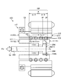
- FIG. 4 is a cross-sectional view of the electric actuator according to the present embodiment.
- FIG. 5 is an exploded perspective view of the electric motor included in the electric actuator according to the present embodiment.
- the electric actuator 100 includes an electric motor 100M and a pulling rod 200.
- the electric motor 100M includes a first motor case 101 that is a cylindrical structure made of aluminum alloy, a second motor case 102 that is a cylindrical structure made of SPCC (cold rolled steel plate), and an aluminum alloy abbreviation. It has the 3rd motor case 103 which is a disk-shaped structure. These are the casing of the electric actuator 100.
- the first motor case 101 and the second motor case 102 are fastened to each other by four bolts 105 (hexagon socket head bolts in this embodiment).
- the second motor case 102 and the third motor case 103 are fastened to each other by caulking portions 104 that are provided in four equal intervals on the circumference of the joint surface between them.
- the electric actuator 100 is fastened to the housing 1C of the automatic transmission 1 shown in FIG. 1 by two bolts 106 attached to the first motor case 101. From the third motor case 103, the signal line 150 of the torque sensor 20 described above is drawn out.
- the electric actuator 100 operates the clutch 400 of the automatic transmission 1 shown in FIG.
- the pulling rod 200 passes through the rotation suppressing member 107.
- the rotation suppressing member 107 is engaged with a part of the pulling rod 200 to suppress the rotation of the pulling rod 200 around the axis.
- the rotation suppression member 107 is a disk-shaped member, and in this embodiment, is fastened and attached to one end portion of the first motor case 101 by six hexagon socket countersunk bolts 108.
- the rotation suppressing member 107 has a through hole 109 through which the pulling rod 200 passes.
- the through hole 109 has an involute spline disposed on the sliding surface with the pulling rod 200.
- the through hole 109 is an involute spline hole.
- the pull bar 200 has a first involute spline shaft 201 disposed on a sliding surface with the rotation suppressing member 107. With such a structure, the pulling rod 200 is guided to be slidable in the axial direction (axis Zs in FIG. 4) and non-rotatable in the circumferential direction with respect to the through hole 109.
- the sliding surface between the first involute spline shaft 201 and the through hole 109 has a slight gap.
- the surface of the first involute spline shaft 201 is coated with a resin so that a change in sliding friction with the through hole 109 is reduced.
- the resin that covers the surface of the first involute spline shaft 201 is, for example, a fluororesin. Further, the surface of the involute of the through hole 109 may be covered with a resin.
- a clutch release bearing 300 is disposed at an end (the other end) 200T2 opposite to the electric motor 100M.
- the clutch release bearing 300 is fastened to the pull rod 200 by a nut 301.
- the nut 301 is a hex nut.
- the nut 301 is provided with U-shaped notches 302 on the sides opposite to the clutch release bearing 300.
- a spring pin 303 is inserted into the U-shaped notch 302.
- the screw shaft 111 has a spiral first groove on the outer peripheral surface.
- the screw shaft 111 is a cylindrical structure having a hollow portion 111I in which a part on the one end portion 200T1 side of the pulling rod 200 is disposed.
- the hollow portion 111I penetrates from one end portion of the screw shaft 111 toward the other end portion.
- the hollow portion 111I has a circular cross-sectional shape orthogonal to the penetrating direction.
- the screw shaft 111 is attached to one end portion 200T1 side of the pull rod 200 and forms a part of the pull rod 200. Therefore, the pulling rod 200 has the spiral first groove 121 on the outer peripheral surface on the one end portion 200T1 side.
- the stator 110 has an annular stator core and a coil wound around the stator core.
- the stator core of the stator 110 is press-fitted into the inner peripheral surface of the second motor case 102.
- the rotor 113 is a cylindrical member having a hollow portion 113I.
- the hollow portion 113I penetrates from one end of the rotor 113 toward the other end.
- the hollow portion 113I has a circular cross-sectional shape orthogonal to the penetrating direction.
- the rotor 113 is disposed on the radially inner side of the stator 110. That is, the stator 110 is disposed on the radially outer side of the rotor 113.
- the pulling rod 200 is disposed in the hollow portion 113I.
- the portion of the pulling rod 200 to which the screw shaft 111 is attached is disposed in the hollow portion 113I.
- the rotor 113 rotates around the Zs axis. That is, the Zs axis is the rotation center axis of the rotor 113.
- the rotor 113 has a spiral second groove 122 corresponding to the first groove 121 of the screw shaft 111 in a part of the inner peripheral surface of the hollow portion 113I.
- the first groove 121 is a male screw groove
- the second groove 122 is a female screw groove.
- the rotor 113 has an opening 113H in which the other end 200T2 side of the pull rod 200 protrudes from the hollow portion 113I.
- the first groove 121 and the second groove 122 face each other. And a rolling path is formed between both.
- a plurality of balls 123 are arranged on the rolling path between the first groove 121 and the second groove 122.
- the ball 123 is a steel ball.
- a so-called flop-over method is adopted as a method for circulating the ball 123.
- the top 112 as a circulating member embedded in the rotor 113 passes the plurality of balls 123 over the land portion of the screw shaft 111 for each lead, returns to the original rolling path, and passes through the rolling path. Circulate.
- the top 112 is attached to the rotor 113 to form a circulation path for the ball 123 and circulates the ball 123.
- three tops 112 are attached at intervals of 120 degrees in the circumferential direction of the rotor 113. Note that the method of circulating the plurality of balls 123 is not limited to the flop-over method.
- the plurality of tops 112 are inserted and embedded in the rotor 113 from the outside in the radial direction of the rotor 113.
- the rotor 113 has a rotor lamination stack 114 as a cylindrical member attached to the outer peripheral surface and the top 112 of the rotor 113.
- the rotor lamination stack 114 is press-fitted into the rotor 113 and fixed thereto. With this structure, the top 112 is fixed integrally with the rotor 113.
- a plurality of magnets 115 are attached to the outer peripheral surface of the rotor lamination stack 114.
- a permanent magnet can be used as the magnet 115.
- the plurality of magnets 115 are bonded and fixed to the rotary stack 114.
- the plurality of magnets 115 may be embedded in the rotary stack 114.
- the pulling rod 200 has an enlarged diameter portion 204 in which a part on the one end portion 200T1 side protrudes in the radial direction.
- the inner diameter of the hollow portion 111 ⁇ / b> I through which the pull rod 200 is disposed is large on the one end portion 200 ⁇ / b> T ⁇ b> 1 side of the pull rod 200.
- the hollow portion 111I has a step portion 111S between a portion having a small inner diameter and a portion having a large inner diameter.
- the enlarged diameter portion 204 is engaged with the stepped portion 111S of the hollow portion 111I.
- a retaining ring 119 ⁇ / b> S is attached to the hollow portion 111 ⁇ / b> I on the one end portion 200 ⁇ / b> T ⁇ b> 1 side of the pulling rod 200.
- the retaining ring 119 ⁇ / b> S is fitted into a groove formed on the inner peripheral surface of the hollow portion 111 ⁇ / b> I and is engaged with the one end portion 200 ⁇ / b> T ⁇ b> 1 of the pulling rod 200.
- the pulling rod 200 engages with the retaining ring 119S attached to the stepped portion 111S of the screw shaft 111 and the hollow portion 111I of the screw shaft 111 in the diameter expanding portion 204.
- the relative movement of the pulling rod 200 and the screw shaft 111 in the axial (Zs axis) direction that is, the extending direction (longitudinal direction) of the pulling rod 200 is restricted.
- An involute spline hole 116 is provided on the inner peripheral surface of the screw shaft 111 and is fitted to the second involute spline shaft 202 of the pull rod 200. Since the involute spline hole 116 and the second involute spline shaft 202 are engaged with each other, a rotational force is transmitted between the screw shaft 111 and the pulling rod 200.
- the first involute spline shaft 201 and the second involute spline shaft 202 are designed with the same specifications. By doing in this way, the advantage that both processing becomes easy is acquired.
- a rolling bearing 117 that rotatably supports the rotor 113 is attached to the first motor case 101.
- the rolling bearing 117 is a ball bearing, but the rolling bearing 117 is not limited to a ball bearing as long as it can support the axial load and the radial load of the rotor 113.
- the rolling bearing 117 is restricted from moving in the axial direction by a shaft retaining ring 118 attached to the outer periphery of the rotor 113 and a hole retaining ring 119B attached to the inner peripheral surface of the first motor case 101.
- the shaft retaining ring 118 is attached between the inner ring 117I of the rolling bearing 117 and the rotor 113, and the hole retaining ring 119B is attached between the first motor case 101 and the outer ring 117S of the rolling bearing 117.
- the rolling bearing 117 can support axial loads in both directions, that is, both loads in the axial (Zs axis) direction.
- the rotor 113 is rotatably supported on a side opposite to the side supported by the rolling bearing 117 by a sliding bearing 120 attached to the third motor case 103.
- the plain bearing 120 supports only the radial load of the rotor 113.
- the rotor 113 is rotatably supported by the first motor case 101 and the third motor case 103 as the casing of the electric motor 100M by the rolling bearing 117 and the sliding bearing 120.
- the rotor 113, the plurality of balls 123, the screw shaft 111, and the top 112 constitute a ball screw.
- the rotor 113 corresponds to the ball screw nut. That is, in this embodiment, the nut of the ball screw and the rotor 113 of the electric motor 100M are shared by the same structure.
- the pulling rod 200 cannot be rotated around the Zs axis by the rotation suppressing member 107, and therefore, the screw shaft 111 attached to the pulling rod 200 cannot be rotated around the Zs axis. .
- the screw shaft 111 tends to rotate together with the rotor 113 by friction with the ball 123.
- the screw shaft 111 is stopped by the rotation suppressing member 107 via the pulling rod 200. Therefore, the screw shaft 111 and the pulling rod 200 are advanced and retracted in the Zs axis direction by the conversion mechanism 125.
- the rotor 113, the plurality of balls 123, the screw shaft 111, and the top 112 convert the rotational motion of the rotor 113 into the linear motion of the screw shaft 111 and the pulling rod 200 to which the screw shaft 111 is attached. It becomes the conversion mechanism 125 to perform.
- the linear motion described above is the extending direction of the pulling rod 200, that is, the longitudinal direction of the pulling rod 200, and is the Zs axis direction that is the rotation center axis of the rotor 113.
- the stator 110 included in the electric motor 100M is disposed on the radially outer side of the rotor 113, and rotates the rotor 113 about the Zs axis. By doing so, the stator 110 moves the pulling rod 200 in the Zs axis direction via the screw shaft 111.
- the rotor 113 of the electric motor 100M rotates so that the pulling rod 200 is drawn into the casing of the electric motor 100M.
- the tensile force at the time of separating the clutch 400 is transmitted to the screw shaft 111 via the enlarged diameter portion 204 of the pull rod 200 and the stepped portion 111S of the screw shaft 111.
- the clutch 400 is engaged, the rotor 113 of the electric motor 100M rotates so that the pull rod 200 protrudes from the housing of the electric motor 100M.
- a compressive force acts on the pulling rod 200, and this compressive force is transmitted to the screw shaft 111 via the retaining ring 119S.
- the pulling rod 200 has a passage 200I extending in the longitudinal direction.
- the passage 200I opens at an end portion on the conversion mechanism 125 side (or the rotor 113 side), that is, one end portion 200T1.
- the signal line 150 of the torque sensor 20 described above is disposed in the passage 200I, and the passage 200I is drawn from an opening 200H opened at one end portion 200T1.
- This signal line is drawn out of the casing of the electric motor 100M through the protective member 130 attached to the third motor case 103.
- the protection member 130 is a member for avoiding direct contact between the signal line and the third motor case 103, and is made of, for example, rubber or resin.
- the transmission path of the rotational force due to the friction between the screw shaft 111 and the ball 123 is in the order of the screw shaft 111, the pulling rod 200, the rotation suppressing member 107, and the first motor case 101 of the electric actuator 100.
- the screw shaft 111 and the pulling rod 200 are fastened together, and the rotation suppressing member 107 and the first motor case 101 are fastened together. Therefore, in the transmission path of the rotational force described above, the relative movement is only between the pulling bar 200 and the rotation suppressing member 107.
- the electric actuator 100 is provided with the first involute spline shaft 201 and the through hole 109 in which the involute spline is disposed in this portion to stop the rotation of the pull rod 200. Therefore, no additional parts are required, and the pull rod 200 can be moved back and forth in the Zs-axis direction, and rotation can be stopped.
- the electric actuator 100 integrally forms the nut of the ball screw and the rotor 113 of the electric motor 100M to advance and retract the screw shaft 111 and the pulling rod 200. Therefore, the number of parts can be reduced and the structure can be simplified. be able to. Furthermore, in the electric actuator 100, since the rotation of the screw shaft 111 due to the rotation of the ball screw nut, that is, the rotor 113 is suppressed by the involute spline integrally formed with each of the pulling rod 200 and the rotation suppressing member 107, The number of parts can be reduced.
- the plurality of tops 112 attached to the rotor 113 are restricted from moving in the radial direction by a single rotor lamination stack 114 that supports the magnet 115 on the outer periphery. For this reason, there is no need to prepare a retaining member or retaining mechanism for the top 112 for each top 112, so that the number of parts can be reduced and the structure can be simplified.
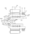
- FIG. 6 is a cross-sectional view showing the electric actuator according to the present embodiment in a state where the clutch release bearing is attached to the pull rod.
- the clutch release bearing 300 is attached to the end (the other end) 200T2 side opposite to the conversion mechanism 125 (or the rotor 113 shown in FIG. 4) shown in FIG. .
- the clutch release bearing 300 gives an input from the pull rod 200 to the clutch 400.
- the pulling rod 200 includes a torque sensor 20 for detecting torque transmitted by the power transmission shaft 500 of the automatic transmission 1 shown in FIG.
- the torque sensor 20 includes a pair of first coils 20A and 20A and a pair of second coils 20B and 20B provided at positions facing these.
- the first coil 20A (+45 degree detection coil) in which the inductance L increases and the second coil 20B ( ⁇ 45 degree detection coil) in which the inductance L decreases are bridge-connected, and the differential voltage is, for example, a lock-in amplifier (LIA).
- LIA lock-in amplifier
- the output voltage proportional to the torque of the power transmission shaft 500 can be detected.
- the torque sensor 20 is a magnetostrictive torque sensor.
- the pair of first coils 20A and 20A detects strain in the tensile direction
- the pair of second coils 20B and 20B detects strain in the compression direction.
- the torque sensor 20 is attached to the outer peripheral portion of the pull rod 200 and detects the torque of the power transmission shaft 500 from the inside of the power transmission shaft 500. In this way, in order to detect torque from the outside of the power transmission shaft 500, it is not necessary to arrange the torque sensor 20 inside the automatic transmission 1 and outside the power transmission shaft 500. As a result, the torque sensor 20 is less susceptible to the influence of the lubricating oil or the like present in the automatic transmission 1, so that durability and reliability are improved.
- the inner surface of the power transmission shaft 500 is preferably covered with a Ni-based (for example, Ni-based metal) thin film.
- Ni-based thin film is Ni—Fe.
- the Ni thin film can be formed, for example, by plating a Ni-based metal or sputtering a Ni-based metal.
- the signal line 150 of the torque sensor 20 moves forward and backward as the pull rod 200 moves forward and backward.
- friction of the signal line 150 in the passage 200I occurs or a load is applied to the joint between the signal line 150 and the first coil 20A and the second coil 20B. May act. Therefore, in this embodiment, as shown in FIG. 6, the signal line 150 is fixed by the clamp member 131 in the opening 200 ⁇ / b> H (see FIG. 4) from which the signal line 150 is drawn from the pulling bar 200, and the passage 200 ⁇ / b> I of the pulling bar 200. The signal line 150 is prevented from moving inside.
- a slack for moving the signal line 150 drawn from the casing of the electric motor 100M is provided outside the electric motor 100M (portion indicated by A in FIG. 6).
- the electric actuator 100 has a unit structure in which the clutch release bearing 300, the torque sensor 20, and the electric motor 100M are integrated through the pulling rod 200. By doing in this way, since the electric actuator 100 can make the pulling rod 200 and the place where the torque sensor 20 is disposed in common, the number of parts can be reduced.
- FIG. 7 is a perspective view showing an example of the arrangement of torque sensors.
- the torque sensor 20 has a pair of first coils 20A and 20A for tensile measurement and second coils 20B and 20B for compression measurement.
- a plurality of torque sensors are arranged by changing the positions of the pulling bar 200 in the axial direction and the circumferential direction.
- the torque sensor (first torque sensor) 20 and the second torque sensor 21 are attached to different positions of the pull rod 200 in the Zs-axis direction and the circumferential direction.
- the first torque sensor 20 has a pair of first coils 20A and 20A and a pair of second coils 20B and 20B.
- the first coil 20A, 20A and the second coil 20B, 20B are in a positional relationship in which the central angle about the Zs axis is 180 degrees in the circumferential direction of the pulling bar 200 (the direction indicated by the arrow C in FIG. 7).
- the second torque sensor 21 has a pair of first coils 21A and 21A and a pair of second coils 21B and 21B.
- the first coils 21 ⁇ / b> A and 21 ⁇ / b> A and the second coils 21 ⁇ / b> B and 21 ⁇ / b> B have a positional relationship in which the central angle about the Zs axis is 180 degrees in the circumferential direction of the pull rod 200.
- the first torque sensor 20 and the second torque sensor 21 are in a positional relationship in which the central angle about the Zs axis is ⁇ degrees in the circumferential direction of the pull rod 200. Further, the first torque sensor 20 and the second torque sensor 21 are arranged with a predetermined interval in the Zs axis direction of the pulling rod 200, that is, in the longitudinal direction or the extending direction. As described above, the first torque sensor 20 and the second torque sensor 21 are attached at different positions in the Zs-axis direction and the circumferential direction of the pulling rod 200, thereby correcting an error caused by the rotational fluctuation of the power transmission shaft 500. can do.
- FIG. 8 is an enlarged cross-sectional view of a portion where the torque sensor is attached.
- the resin 30 is interposed between the torque sensor 20, more specifically, between the first coil 20 ⁇ / b> A and the second coil 20 ⁇ / b> B and the pulling bar 200.
- the resin 30 for example, 66 nylon or PPS (Polyphenylene sulfide) can be used. In general, such a resin has a relative magnetic permeability almost equal to that of air and is very small, so that it is difficult to pass a magnetic flux.
- the resin 30 can suppress the magnetic flux generated from the first coil 20 ⁇ / b> A and the second coil 20 ⁇ / b> B from leaking to the pulling rod 200 and reducing the magnetic flux passing through the power transmission shaft 500.
- the pulling rod 200 is made of metal, the leakage of magnetic flux to the pulling rod 200 is suppressed, so that a decrease in sensitivity of the torque sensor 20 is suppressed.
- the pulling rod 200 may be made of a nonmagnetic material.
- a nonmagnetic material is difficult to pass magnetic flux because of its low relative permeability. For this reason, the leakage of the magnetic flux to the pulling rod 200 can be further reduced, and the decrease in sensitivity of the torque sensor 20 can be further suppressed.
- a resin can be used as the nonmagnetic material.
- the first coil 20 ⁇ / b> A and the second coil 20 ⁇ / b> B may be integrally formed with the pull rod 200 inside the pull rod 200. By doing in this way, the leakage of the magnetic flux to the pulling rod 200 can be further reduced, and the decrease in sensitivity of the torque sensor 20 can be further suppressed. Further, by integrally molding the first coil 20A and the second coil 20B together with the pull bar 200, the pull bar 200 and the torque sensor 20 can be easily assembled.
- the torque sensor 20 detects the torque of the power transmission shaft 500 using the magnetostrictive effect.
- the magnetic fluid 31 may exist between the torque sensor 20 and the power transmission shaft 500.
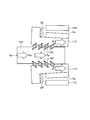
- FIG. 9, FIG. 10, FIG. 12, and FIG. 13 are schematic views showing the relationship of force between the screw shaft and the rotor provided in the electric actuator.
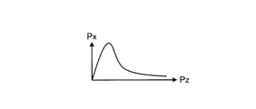
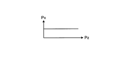
- 11 and 14 are diagrams showing the distribution of the surface pressure acting on the balls included in the electric actuator according to the present embodiment.
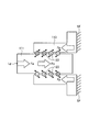
- FIG. 15 and FIG. 16 are schematic views showing the relationship of force between the screw shaft and the rotor provided in the electric actuator according to the present embodiment.
- the electric actuator 100 shown in FIG. 4 converts the rotational motion of the rotor 113 into the linear motion of the screw shaft 111 and the pulling rod 200 using the conversion mechanism 125 using a ball screw. In this case, it is necessary to support either the rotor 113 or the screw shaft 111 as a nut so that it cannot rotate but can advance and retreat in the axial direction.
- either the rotor 113 or the screw shaft 111 has a structure that can rotate and cannot advance or retract in the axial direction. If the rotor 113 can be rotated and the screw shaft 111 and the pulling rod 200 can be advanced and retracted, the rotor 113 requires a bearing that transmits a load in the axial direction to the casing of the electric motor 100M.
- the rolling bearing 117, the shaft retaining ring 118, and the hole retaining ring 119B shown in FIG. 4 apply force in the direction from the rotor 113 to the axis (the Zs axis and the rotation center axis of the rotor 113). Is transmitted to the first motor case 101.
- the conversion mechanism 125 uses a ball screw, but if a load is not evenly applied to the plurality of balls 123, there will be a ball 123 that handles the load excessively. As a result, there is a possibility that the surface pressure of the ball 123 that handles the load excessively increases at the point of contact with the race (referred to as the ball contact point as appropriate). For this reason, in order to suppress an excessive increase in the surface pressure at the ball contact point, it is desirable that a load be applied to the plurality of balls 123 as evenly as possible.
- FIG. 11 shows the relationship between the surface pressure Px at the ball contact point and the position Pz in the axial direction when the ball 123 does not receive a load equally (the same applies to FIG. 14).
- the load support portion SF is, for example, a housing of the electric motor 100M (the first motor case 101 and the like in the present embodiment).
- FIG. 9 shows a case where a load (compression load) Fa is applied to the screw shaft 111 in the compression direction.
- Lp in the figure indicates the load application point of the screw shaft 111 (the same applies hereinafter).
- the compressive load Fa is transmitted to the rotor 113 as a nut via the ball 123 and is transmitted to the load support portion SF via the rotor 113.
- the rotor 113 is loaded with a load (tensile load) Ft in the pulling direction.
- FIG. 10 shows a case where a load (tensile load) Fb in the tensile direction is applied to the screw shaft 111.
- the tensile load Fb is transmitted to the rotor 113 via the ball 123 and is transmitted to the load support portion SF via the rotor 113.
- the rotor 113 is loaded with a load (compression load) Fp in the compression direction.
- the input position of the load to the screw shaft 111 and the load support portion SF that receives the load from the rotor 113 are in the region where the plurality of balls 123 are arranged. On the same side in the Zs axis direction.
- the electric actuator 100 has a ball screw nut formed on the rotor 113.
- the spread due to the elastic deformation of the rotor 113 increases at a position where the load is large, and the spread due to the elastic deformation of the rotor 113 decreases at a position where the load is small.
- the diameter of the rotor 113 changes depending on the position in the axial direction, and the air gap Ga between the rotor 113 and the stator 110 may become non-uniform.
- FIGS. 12 and 13 are different from the examples shown in FIGS. 9 and 10 in that the input position of the load to the screw shaft 111 and the load support portion SF that receives the load from the rotor 113 are Zs. In the axial direction, it is on both sides of an area (ball arrangement area) where a plurality of balls 123 are arranged.
- the ball arrangement area is an effective track portion of the ball screw.
- the compression load Fa from the pulling rod 200 is input to the screw shaft 111 via the retaining ring 119S of the pulling rod 200.
- the tensile load Fb from the pulling rod 200 is input from the enlarged diameter portion 204 of the pulling rod 200 to the screw shaft 111 via the stepped portion 111 ⁇ / b> S of the screw shaft 111.
- the load input position (load input position) IP to the screw shaft 111 is a portion where the step portion 111S and the enlarged diameter portion 204 are in contact with each other and a portion where the retaining ring 119S is attached to the screw shaft 111.
- the load from the rotor 113 is increased from the enlarged diameter portion 113 ⁇ / b> F of the rotor 113 or the shaft retaining ring 118 attached to the rotor 113 via the rolling bearing 117 and the hole retaining ring 119 ⁇ / b> B. It is transmitted to the first motor case 101. That is, the load support portion SF that receives a load from the rotor 113 is a portion to which the hole retaining ring 119B of the first motor case 101 is attached.
- the load input position IP and the load support portion SF are arranged on both sides of the ball arrangement area in the axis Zs direction. For this reason, as shown in FIG. 15, when a compressive load Fa is generated in the pulling rod 200 and this is input to the screw shaft 111, the portion where the first groove 121 of the screw shaft 111 is formed and the first of the rotor 113. A tensile load Ft is generated in each of the portions where the two grooves 122 are formed. Further, as shown in FIG. 16, when a tensile load Fb is generated in the pulling rod 200 and this is input to the screw shaft 111, the portion where the first groove 121 of the screw shaft 111 is formed and the second of the rotor 113. A compressive load Fp is generated in any portion where the groove 122 is formed.
- the portion where the first groove 121 of the screw shaft 111 which is a part of the pulling rod 200 is formed and the portion where the second groove 122 of the rotor 113 is formed are Zs.
- the direction of the load in the axial direction is the same.
- the surface pressure Px becomes substantially constant depending on the position Pz in the axial direction. For this reason, since the electric motor 100M suppresses variations in the air gap Ga, the motor 100M can stably generate torque.
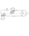
- 17 and 18 are diagrams showing the relationship among the ball arrangement region, the load input position of the screw shaft, and the load application position of the rolling bearing.
- the load input position IP to the screw shaft 111 exists on the one end 111T1 side of the ball shaft 111. More specifically, the load input position IP to the screw shaft 111 is arranged in the ball arrangement area BR. Further, the load application position Lb of the rolling bearing 117 exists on the other end 111T2 side of the ball shaft 111.
- both load input positions IP are positions away from the rolling bearing 117 attached to the other end 113T2 side of the rotor 113 relative to the ⁇ / 2 position A in the axial (Zs axis) direction, That is, it is preferable to be on the one end 111T1 side of the screw shaft 111.
- the electric actuator 100 can reduce the influence of both the compressive load Fp and the tensile load Ft acting, so that the surface pressure at the ball contact point becomes substantially constant depending on the position in the axial direction. For this reason, since the electric actuator 100 can suppress variation in the air gap, the electric actuator 100 can stably generate torque.
- the one end 111T1 of the screw shaft 111 is on one end 200T1 side of the pulling rod 200 and one end 113T1 side of the rotor 113.
- ⁇ is the dimension of the ball placement region BR in the direction of the screw shaft 111 (Zs axis).
- the position A of ⁇ / 2 is the central portion of the ball arrangement region BR in the axis (Zs axis) direction.
- both load input positions IP are from a rolling bearing 117 attached to the other end 113T2 side of the rotor 113 with respect to the ball arrangement region BR in the axial (Zs axis) direction. It is preferable to set it as a distant position, that is, on one end 111T1 side of the screw shaft 111.
- the load input position IP of the screw shaft 111 and the load application position Lb of the rolling bearing 117 are present on both sides of the ball placement region BR in the axis (Zs axis) direction of the screw shaft 111 so as to sandwich this. Will be placed.
- the electric actuator 100a can avoid that both the compression load Fp and the tensile load Ft act on the screw shaft 111 and the rotor 113.
- the electric actuator 100a can avoid the influence of both the compressive load Fp and the tensile load Ft acting, the surface pressure of the ball contact point becomes substantially constant depending on the position in the axial direction. For this reason, since the electric actuator 100a can further suppress variation in the air gap, it can stably generate torque.
- the load application position Lb of the rolling bearing 117 is closer to the rolling bearing 117 than the ball placement region BR.
- FIG. 19 is a view showing an electric actuator according to a modification of the present embodiment.
- the rotor 113b included in the electric actuator 100b is rotatably supported by a housing to which the stator 110 is attached via a rolling bearing 117 on the side opposite to the opening 113H. That is, the rotor 113b has the rolling bearing 117 attached to one end 113T1 side, that is, the side opposite to the opening 113H, and the sliding bearing 120 attached to the other end 113T2.
- the rolling bearing 117 is disposed on the one end 111T1 side of the screw shaft 111b.
- the screw shaft 111 has an opening 111H into which the pulling rod 200b is inserted on the other end 111T2 side, that is, on the other end 113T2 side (opening 113H side) of the rotor 113b.
- the pulling rod 200 has a diameter-enlarged portion 204b that projects outward in the radial direction on the one end portion 200T1 side.
- a rod-shaped portion 200bb extends from the enlarged diameter portion 204b toward one end portion 200T1.
- the rod-shaped portion 200bb is inserted into a step portion through hole 111HI that passes through the step portion 111Sb of the screw shaft 111.
- the load input position IP of the screw shaft 111b is a portion where the step portion 111Sb and the enlarged diameter portion 204b are in contact with each other on the other end 111T2 side of the screw shaft 111 and a portion where the retaining ring 119S is attached to the screw shaft 111S.
- the load input position IP of the screw shaft 111b and the load application position Lb of the rolling bearing 117 are arranged on both sides of the ball arrangement region BR in the direction of these axes (Zs axis). That is, both the load input positions IP are arranged at positions farther from the rolling bearing 117 than the ball arrangement area BR in the axial (Zs axis) direction.
- the electric actuator 100b can avoid the influence by both a compressive load and a tensile load acting on the screw shaft 111b and the rotor 113b. For this reason, in the electric actuator 100b, the surface pressure of the ball contact point is substantially constant depending on the position in the axial direction. As a result, the electric actuator 100b can further suppress variations in the air gap, and can stably generate torque.
- both load input positions IP are separated from the rolling bearing 117 attached to the one end 113T1 side of the rotor 113b rather than the center of the ball arrangement region BR in the axial (Zs axis) direction.
- the other position 111T2 side of the screw shaft 111b may be used.
- FIG. 20 is a cross-sectional view for illustrating the arrangement of the sealing member of the rolling bearing in the electric actuator according to the present embodiment.
- the rotor 113 is integrated with the ball screw nut.
- the rolling bearing 117 is disposed adjacent to the rotor 113 in the first to third motor cases 101, 102, and 103 as a housing of the electric actuator 100 or the like.
- the lubricating oil or grease of the ball screw and the rolling bearing 117 may enter the inside of the housing, more specifically, the space where the stator 110 is arranged.
- the electric actuator 100 or the like may not be able to maximize its performance.
- the electric actuator 100 or the like needs to have a structure that does not allow lubricating oil, grease, or the like to enter the space in which the stator 110 is disposed inside the housing.
- the sealing member 50 that seals the space between the inner ring 117I and the outer ring 117S of the rolling bearing 117 is on the inner side of the housing, and the rotor 113 and the stator 110 are arranged. Have on the side.
- the sealing member 50 may be provided on the rolling bearing 117 included in the electric actuators 100, 110a, and 100b described above.
- the electric actuator 100 or the like When the electric actuator 100 or the like according to the present embodiment is used for a vehicle such as an automobile, the electric actuator 100 or the like is configured to have as few parts as possible in order to reduce the mass as much as possible and reduce the cost as much as possible. Is desirable. Therefore, a part of the rotor 113 that also serves as a nut of the ball screw may be used also as the inner ring 117I of the rolling bearing 117 that supports the rotor 113.
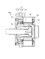
- FIG. 21 is a cross-sectional view showing an electric actuator including a rotor that also serves as an inner ring of a rolling bearing.
- FIG. 22 is an enlarged view showing the rolling bearing of the electric actuator shown in FIG.
- the rotor 113d of the electric actuator 100c is an inner ring 113IR of the rolling bearing 117d on the opening 113Hd side facing the rotation suppressing member 107.
- the rolling bearing 117d includes the inner ring 113IR, rolling elements 117B, and an outer ring 117S. By doing so, the number of parts of the electric actuator 100d is reduced.
- the same material can be used.
- An example of such a material is a carburized material of SCM420H.
- the shoulder height of the inner ring 113IR is increased as shown in FIG. That is, the shoulder 113T (the opening 113Hd side shown in FIG. 18) of the inner ring 113IR is extended in the radial direction (the direction indicated by the arrow r in FIG. 19), and is more than the shoulder 113T than the opposite side across the rolling element 117B. Increase the diameter.
Landscapes
- Engineering & Computer Science (AREA)
- General Engineering & Computer Science (AREA)
- Mechanical Engineering (AREA)
- Power Engineering (AREA)
- Microelectronics & Electronic Packaging (AREA)
- Physics & Mathematics (AREA)
- Electromagnetism (AREA)
- Transmission Devices (AREA)
- Connection Of Motors, Electrical Generators, Mechanical Devices, And The Like (AREA)
Priority Applications (2)
| Application Number | Priority Date | Filing Date | Title |
|---|---|---|---|
| EP12881127.0A EP2873891A1 (fr) | 2012-07-10 | 2012-08-03 | Actionneur électrique |
| US14/413,040 US20150171702A1 (en) | 2012-07-10 | 2012-08-03 | Electric actuator |
Applications Claiming Priority (4)
| Application Number | Priority Date | Filing Date | Title |
|---|---|---|---|
| JP2012155057A JP2014018007A (ja) | 2012-07-10 | 2012-07-10 | 電動アクチュエータ |
| JP2012155058A JP2014016006A (ja) | 2012-07-10 | 2012-07-10 | 電動アクチュエータ |
| JP2012-155058 | 2012-07-10 | ||
| JP2012-155057 | 2012-07-10 |
Publications (1)
| Publication Number | Publication Date |
|---|---|
| WO2014010103A1 true WO2014010103A1 (fr) | 2014-01-16 |
Family
ID=49915595
Family Applications (1)
| Application Number | Title | Priority Date | Filing Date |
|---|---|---|---|
| PCT/JP2012/069904 Ceased WO2014010103A1 (fr) | 2012-07-10 | 2012-08-03 | Actionneur électrique |
Country Status (3)
| Country | Link |
|---|---|
| US (1) | US20150171702A1 (fr) |
| EP (1) | EP2873891A1 (fr) |
| WO (1) | WO2014010103A1 (fr) |
Families Citing this family (13)
| Publication number | Priority date | Publication date | Assignee | Title |
|---|---|---|---|---|
| FR3005130B1 (fr) * | 2013-04-24 | 2015-04-17 | Sonceboz Sa | Actionneur electrique a tige filetee |
| JP6303770B2 (ja) * | 2014-04-25 | 2018-04-04 | アイシン・エィ・ダブリュ株式会社 | 駆動装置 |
| DE102014213445A1 (de) * | 2014-07-10 | 2016-01-14 | Deere & Company | Schrägfördererzusammenbau für einen Mähdrescher |
| US10480628B2 (en) * | 2015-10-08 | 2019-11-19 | Soucy International Inc. | Electric actuator |
| US10094427B2 (en) * | 2015-10-20 | 2018-10-09 | GM Global Technology Operations LLC | Ball cam actuated dog clutch |
| KR102353513B1 (ko) * | 2017-03-16 | 2022-01-20 | 주식회사 히타치엘지 데이터 스토리지 코리아 | 회전 거리 측정 장치 |
| DE102018131607A1 (de) * | 2018-12-10 | 2020-06-10 | Schaeffler Technologies AG & Co. KG | Rotor mit einteiligem Gewinde, sowie Elektromotor, Aktor und Parksperre |
| DE102019206232A1 (de) * | 2019-04-30 | 2020-11-05 | Zf Friedrichshafen Ag | Kupplungsbetätigungseinheit |
| DE102019219813A1 (de) * | 2019-12-17 | 2021-06-17 | Zf Friedrichshafen Ag | Aktuatorvorrichtung zur Erzeugung einer longitudinalen Stellbewegung |
| JP2022154362A (ja) * | 2021-03-30 | 2022-10-13 | 本田技研工業株式会社 | サスペンション装置 |
| WO2023155949A1 (fr) * | 2022-02-15 | 2023-08-24 | Schaeffler Technologies AG & Co. KG | Dispositif d'ajustement linéaire et unité d'ajustement |
| CN114407639B (zh) * | 2022-03-11 | 2022-08-19 | 深圳市悦成汽车技术有限公司 | 一种混动汽车的多模式变速箱总成 |
| CN119795239A (zh) * | 2025-01-23 | 2025-04-11 | 上海智元新创技术有限公司 | 关节模组和灵巧手 |
Citations (10)
| Publication number | Priority date | Publication date | Assignee | Title |
|---|---|---|---|---|
| JPH0288139U (fr) * | 1988-12-22 | 1990-07-12 | ||
| JPH11304607A (ja) * | 1998-04-16 | 1999-11-05 | Nippon Seiko Kk | トルクセンサ |
| JP2001050300A (ja) * | 1999-08-05 | 2001-02-23 | Exedy Corp | クラッチレリーズ装置及びそれが用いられるクラッチ |
| JP2001289301A (ja) * | 2000-04-03 | 2001-10-19 | Ntn Corp | ボールねじおよびそれを具備する電動パワーステアリング装置 |
| JP2004225723A (ja) * | 2003-01-20 | 2004-08-12 | Jatco Ltd | 電磁多板クラッチの制御装置 |
| JP2005233228A (ja) * | 2004-02-17 | 2005-09-02 | Ntn Corp | 電動式ブレーキ装置 |
| JP2006071009A (ja) | 2004-09-02 | 2006-03-16 | Nsk Ltd | アクチュエータ |
| JP2007146874A (ja) * | 2005-11-24 | 2007-06-14 | Toyota Motor Corp | ボールねじおよびボールねじ用ナット製造方法 |
| JP2011179583A (ja) * | 2010-03-01 | 2011-09-15 | Jtekt Corp | 電動アクチュエータおよび変速機駆動装置 |
| JP2012039765A (ja) * | 2010-08-06 | 2012-02-23 | Ntn Corp | 電動アクチュエータ |
Family Cites Families (3)
| Publication number | Priority date | Publication date | Assignee | Title |
|---|---|---|---|---|
| JP4182726B2 (ja) * | 2002-02-20 | 2008-11-19 | 日本精工株式会社 | リニアアクチュエータ |
| JP5517869B2 (ja) * | 2009-11-27 | 2014-06-11 | Ntn株式会社 | インホイール型モータ内蔵センサ付き車輪用軸受装置 |
| CN102438852B (zh) * | 2010-05-21 | 2014-10-15 | 日本精工株式会社 | 轮内马达 |
-
2012
- 2012-08-03 US US14/413,040 patent/US20150171702A1/en not_active Abandoned
- 2012-08-03 WO PCT/JP2012/069904 patent/WO2014010103A1/fr not_active Ceased
- 2012-08-03 EP EP12881127.0A patent/EP2873891A1/fr not_active Withdrawn
Patent Citations (10)
| Publication number | Priority date | Publication date | Assignee | Title |
|---|---|---|---|---|
| JPH0288139U (fr) * | 1988-12-22 | 1990-07-12 | ||
| JPH11304607A (ja) * | 1998-04-16 | 1999-11-05 | Nippon Seiko Kk | トルクセンサ |
| JP2001050300A (ja) * | 1999-08-05 | 2001-02-23 | Exedy Corp | クラッチレリーズ装置及びそれが用いられるクラッチ |
| JP2001289301A (ja) * | 2000-04-03 | 2001-10-19 | Ntn Corp | ボールねじおよびそれを具備する電動パワーステアリング装置 |
| JP2004225723A (ja) * | 2003-01-20 | 2004-08-12 | Jatco Ltd | 電磁多板クラッチの制御装置 |
| JP2005233228A (ja) * | 2004-02-17 | 2005-09-02 | Ntn Corp | 電動式ブレーキ装置 |
| JP2006071009A (ja) | 2004-09-02 | 2006-03-16 | Nsk Ltd | アクチュエータ |
| JP2007146874A (ja) * | 2005-11-24 | 2007-06-14 | Toyota Motor Corp | ボールねじおよびボールねじ用ナット製造方法 |
| JP2011179583A (ja) * | 2010-03-01 | 2011-09-15 | Jtekt Corp | 電動アクチュエータおよび変速機駆動装置 |
| JP2012039765A (ja) * | 2010-08-06 | 2012-02-23 | Ntn Corp | 電動アクチュエータ |
Also Published As
| Publication number | Publication date |
|---|---|
| US20150171702A1 (en) | 2015-06-18 |
| EP2873891A1 (fr) | 2015-05-20 |
Similar Documents
| Publication | Publication Date | Title |
|---|---|---|
| WO2014010103A1 (fr) | Actionneur électrique | |
| JP2014018007A (ja) | 電動アクチュエータ | |
| JP7272216B2 (ja) | クラッチ装置 | |
| US11802594B2 (en) | Clutch device | |
| US11773915B2 (en) | Clutch device | |
| US11815136B2 (en) | Clutch device | |
| US11808307B2 (en) | Clutch device | |
| US11781605B2 (en) | Clutch device | |
| US11796012B2 (en) | Clutch device | |
| JP2014016006A (ja) | 電動アクチュエータ | |
| US20190123616A1 (en) | Electric linear actuator | |
| WO2022118833A1 (fr) | Dispositif d'embrayage | |
| JP7563164B2 (ja) | 回転式アクチュエータ | |
| WO2018088244A1 (fr) | Actionneur électrique à entraînement direct | |
| JP2022170458A (ja) | クラッチアクチュエータ | |
| JP2022119644A (ja) | クラッチ装置 | |
| US11994176B2 (en) | Clutch actuator | |
| JP2022119622A (ja) | クラッチ装置 | |
| JP7559711B2 (ja) | ギヤードモータ、および、それを用いたクラッチアクチュエータ | |
| US20230313848A1 (en) | Clutch device | |
| US20230341004A1 (en) | Clutch device | |
| WO2023276717A1 (fr) | Actionneur d'embrayage | |
| WO2023276719A1 (fr) | Actionneur d'embrayage | |
| WO2022118839A1 (fr) | Dispositif d'embrayage | |
| JP2023006290A (ja) | クラッチアクチュエータ |
Legal Events
| Date | Code | Title | Description |
|---|---|---|---|
| 121 | Ep: the epo has been informed by wipo that ep was designated in this application |
Ref document number: 12881127 Country of ref document: EP Kind code of ref document: A1 |
|
| WWE | Wipo information: entry into national phase |
Ref document number: 2012881127 Country of ref document: EP |
|
| NENP | Non-entry into the national phase |
Ref country code: DE |
|
| WWE | Wipo information: entry into national phase |
Ref document number: 14413040 Country of ref document: US |