WO2014010142A1 - Échangeur de chaleur et dispositif de nettoyage sanitaire le comportant - Google Patents
Échangeur de chaleur et dispositif de nettoyage sanitaire le comportant Download PDFInfo
- Publication number
- WO2014010142A1 WO2014010142A1 PCT/JP2013/001287 JP2013001287W WO2014010142A1 WO 2014010142 A1 WO2014010142 A1 WO 2014010142A1 JP 2013001287 W JP2013001287 W JP 2013001287W WO 2014010142 A1 WO2014010142 A1 WO 2014010142A1
- Authority
- WO
- WIPO (PCT)
- Prior art keywords
- heater
- flow path
- heat exchanger
- forming member
- heat
- Prior art date
- Legal status (The legal status is an assumption and is not a legal conclusion. Google has not performed a legal analysis and makes no representation as to the accuracy of the status listed.)
- Ceased
Links
Images


Classifications
-
- E—FIXED CONSTRUCTIONS
- E03—WATER SUPPLY; SEWERAGE
- E03D—WATER-CLOSETS OR URINALS WITH FLUSHING DEVICES; FLUSHING VALVES THEREFOR
- E03D9/00—Sanitary or other accessories for lavatories ; Devices for cleaning or disinfecting the toilet room or the toilet bowl; Devices for eliminating smells
- E03D9/08—Devices in the bowl producing upwardly-directed sprays; Modifications of the bowl for use with such devices ; Bidets; Combinations of bowls with urinals or bidets; Hot-air or other devices mounted in or on the bowl, urinal or bidet for cleaning or disinfecting
-
- F—MECHANICAL ENGINEERING; LIGHTING; HEATING; WEAPONS; BLASTING
- F24—HEATING; RANGES; VENTILATING
- F24H—FLUID HEATERS, e.g. WATER OR AIR HEATERS, HAVING HEAT-GENERATING MEANS, e.g. HEAT PUMPS, IN GENERAL
- F24H1/00—Water heaters, e.g. boilers, continuous-flow heaters or water-storage heaters
- F24H1/10—Continuous-flow heaters, i.e. heaters in which heat is generated only while the water is flowing, e.g. with direct contact of the water with the heating medium
- F24H1/12—Continuous-flow heaters, i.e. heaters in which heat is generated only while the water is flowing, e.g. with direct contact of the water with the heating medium in which the water is kept separate from the heating medium
- F24H1/121—Continuous-flow heaters, i.e. heaters in which heat is generated only while the water is flowing, e.g. with direct contact of the water with the heating medium in which the water is kept separate from the heating medium using electric energy supply
-
- F—MECHANICAL ENGINEERING; LIGHTING; HEATING; WEAPONS; BLASTING
- F24—HEATING; RANGES; VENTILATING
- F24H—FLUID HEATERS, e.g. WATER OR AIR HEATERS, HAVING HEAT-GENERATING MEANS, e.g. HEAT PUMPS, IN GENERAL
- F24H9/00—Details
- F24H9/0005—Details for water heaters
- F24H9/001—Guiding means
- F24H9/0015—Guiding means in water channels
-
- F—MECHANICAL ENGINEERING; LIGHTING; HEATING; WEAPONS; BLASTING
- F24—HEATING; RANGES; VENTILATING
- F24H—FLUID HEATERS, e.g. WATER OR AIR HEATERS, HAVING HEAT-GENERATING MEANS, e.g. HEAT PUMPS, IN GENERAL
- F24H9/00—Details
- F24H9/18—Arrangement or mounting of grates or heating means
- F24H9/1809—Arrangement or mounting of grates or heating means for water heaters
- F24H9/1818—Arrangement or mounting of electric heating means
-
- H—ELECTRICITY
- H05—ELECTRIC TECHNIQUES NOT OTHERWISE PROVIDED FOR
- H05B—ELECTRIC HEATING; ELECTRIC LIGHT SOURCES NOT OTHERWISE PROVIDED FOR; CIRCUIT ARRANGEMENTS FOR ELECTRIC LIGHT SOURCES, IN GENERAL
- H05B3/00—Ohmic-resistance heating
- H05B3/10—Heating elements characterised by the composition or nature of the materials or by the arrangement of the conductor
- H05B3/12—Heating elements characterised by the composition or nature of the materials or by the arrangement of the conductor characterised by the composition or nature of the conductive material
- H05B3/14—Heating elements characterised by the composition or nature of the materials or by the arrangement of the conductor characterised by the composition or nature of the conductive material the material being non-metallic
- H05B3/141—Conductive ceramics, e.g. metal oxides, metal carbides, barium titanate, ferrites, zirconia, vitrous compounds
-
- H—ELECTRICITY
- H05—ELECTRIC TECHNIQUES NOT OTHERWISE PROVIDED FOR
- H05B—ELECTRIC HEATING; ELECTRIC LIGHT SOURCES NOT OTHERWISE PROVIDED FOR; CIRCUIT ARRANGEMENTS FOR ELECTRIC LIGHT SOURCES, IN GENERAL
- H05B3/00—Ohmic-resistance heating
- H05B3/20—Heating elements having extended surface area substantially in a two-dimensional [2D] plane, e.g. plate-heater
- H05B3/22—Heating elements having extended surface area substantially in a two-dimensional [2D] plane, e.g. plate-heater non-flexible
- H05B3/26—Heating elements having extended surface area substantially in a two-dimensional [2D] plane, e.g. plate-heater non-flexible heating conductor mounted on insulating base
- H05B3/265—Heating elements having extended surface area substantially in a two-dimensional [2D] plane, e.g. plate-heater non-flexible heating conductor mounted on insulating base the insulating base being an inorganic material, e.g. ceramic
-
- F—MECHANICAL ENGINEERING; LIGHTING; HEATING; WEAPONS; BLASTING
- F24—HEATING; RANGES; VENTILATING
- F24H—FLUID HEATERS, e.g. WATER OR AIR HEATERS, HAVING HEAT-GENERATING MEANS, e.g. HEAT PUMPS, IN GENERAL
- F24H2250/00—Electrical heat generating means
- F24H2250/02—Resistances
-
- H—ELECTRICITY
- H05—ELECTRIC TECHNIQUES NOT OTHERWISE PROVIDED FOR
- H05B—ELECTRIC HEATING; ELECTRIC LIGHT SOURCES NOT OTHERWISE PROVIDED FOR; CIRCUIT ARRANGEMENTS FOR ELECTRIC LIGHT SOURCES, IN GENERAL
- H05B2203/00—Aspects relating to Ohmic resistive heating covered by group H05B3/00
- H05B2203/002—Heaters using a particular layout for the resistive material or resistive elements
- H05B2203/003—Heaters using a particular layout for the resistive material or resistive elements using serpentine layout
-
- H—ELECTRICITY
- H05—ELECTRIC TECHNIQUES NOT OTHERWISE PROVIDED FOR
- H05B—ELECTRIC HEATING; ELECTRIC LIGHT SOURCES NOT OTHERWISE PROVIDED FOR; CIRCUIT ARRANGEMENTS FOR ELECTRIC LIGHT SOURCES, IN GENERAL
- H05B2203/00—Aspects relating to Ohmic resistive heating covered by group H05B3/00
- H05B2203/013—Heaters using resistive films or coatings
Definitions
- the present invention relates to an instantaneous heating type heat exchanger used in a sanitary washing apparatus for washing a human body part with warm water after a toilet and a sanitary washing apparatus provided with the same.
- sanitary washing devices have been equipped with a heat exchanger for making the wash water an appropriate temperature when washing the human body part after the toilet with water.
- a heat exchanger for making the wash water an appropriate temperature when washing the human body part after the toilet with water.
- Various types of heat exchangers have been developed, and for example, a flat plate heat exchanger is disclosed (for example, see Patent Document 1).
- a flat heater is housed vertically in a rectangular parallelepiped casing having a small thickness dimension, and the horizontal direction along each of the heat transfer surfaces on the front and back of the flat heater.
- the two flow paths meandering to the upper side and formed upward are formed.
- the cleaning water that flows is heated to an appropriate temperature by allowing the cleaning water to flow along each flow path while heating the flat heater.
- the heat exchanger disclosed in Patent Document 1 speeds up and equalizes the flow rate of the washing water by reducing the flow path cross-sectional area. Thereby, while improving the heat transfer rate to washing water, it is supposed that size reduction can be attained.
- a heat exchanger for instant water heating that heats cleaning water in a sanitary cleaning device is used to heat water with a maximum flow rate of about 0.5 L / min to 40 ° C. hot water with 5 ° C. incoming water. About 1200W is required as input power. Therefore, a heater having a relatively large watt density of about 20 W / cm 2 to 50 W / cm 2 is used as the flat heater.
- the maximum flow rate passing through the heat exchanger is as low as about 0.5 L / min. For this reason, there are problems such as stability of operation in the heat exchanger and adhesion of scale to the heater surface when used in a hard water area.
- a partition rib is provided on the inner wall surface side of the casing constituting the outer frame of the heat exchanger in the vicinity of the flat heater. The cleaning water is passed through a flow path formed between the partition rib and the flat heater. Thereby, the heat transfer by forced convection heat exchange is promoted.
- a conventional heat exchanger using a flat heater induces forced convection on the heater surface, and ensures that the flow velocity is maintained while flowing cleaning water uniformly over the heater surface, thereby transferring heat on the heater surface. It is configured to promote
- the partition rib provided in the vicinity of the flat heater is formed by injection molding of a resin material integrally with the casing of the heat exchanger. Therefore, a uniform gap cannot be formed between the tip of the partition rib and the flat heater surface due to thermal shrinkage or molding warpage during the molding of the casing. Thereby, at the time of heat exchange, since washing water flows as a leak flow through a non-uniform gap, temperature unevenness occurs on the surface of the flat heater. Further, there is no problem if the bubbles generated in the main flow path flow along the main flow path and are eliminated.
- the leakage flow increases, the leakage flow flows in a direction perpendicular to the main flow path direction, so that bubbles may not be discharged downstream and remain as flow obstructions in the flow path.
- the surface of the heater where the foam exists is overheated.
- scale means that components such as calcium and magnesium contained in cleaning water such as tap water are deposited and deposited as carbonates or hydrogen carbonates, and the same applies to the following.
- the portion where the tip of the partition rib made of resin material and the surface of the heater are in close contact with each other is thermally insulated and becomes locally hot. Therefore, if a ceramic heater is used as the heater, cracking of the ceramic heater is further promoted. Moreover, since the tip of the partition rib made of a resin material is vulnerable to high temperatures, there is a problem that the partition rib is damaged by heat.
- a heat exchanger includes a casing having a water inlet and a water outlet, a heater contained in the casing and containing a heating resistor, and a fluid flowing from the water inlet to the water outlet.
- the heat exchange flow path is configured by bringing the other surface of the flow path forming member into close contact with the heat transfer surface of the heater and abutting the tip end portion of the partition rib of the flow path forming member on the inner wall surface of the casing.
- the partition ribs of the flow path forming member having spring properties can absorb the dimensional variation of the heater and the casing, and the inner wall surface of the casing and the partition rib can be brought into contact with each other reliably.
- the above heat exchanger is provided.
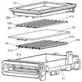
- FIG. 1 is an external perspective view showing a sanitary washing apparatus including a heat exchanger according to an embodiment of the present invention.
- FIG. 2 is a front view showing an external configuration of the heat exchanger according to the embodiment of the present invention.
- FIG. 3 is a right side view of the heat exchanger shown in FIG. 4 is a cross-sectional view of the heat exchanger shown in FIG. 2 taken along line 4-4.
- FIG. 5 is an exploded perspective view of the heat exchanger shown in FIG.
- FIG. 6 is a plan view showing an example of a print pattern of a heating resistor formed on the heater of the heat exchanger shown in FIG.
- FIG. 7 is a plan view showing another example of the print pattern of the heating resistor formed on the heater of the heat exchanger shown in FIG.
- FIG. 1 is an external perspective view showing a sanitary washing apparatus including a heat exchanger according to an embodiment of the present invention.
- FIG. 2 is a front view showing an external configuration of the heat exchanger according to the embodiment of the present invention
- FIG. 8 is a perspective view showing a state in which the tip of the second partition rib of the heat exchanger shown in FIG. 4 is in contact with the inner wall surface of the second casing member.
- FIG. 9 is a perspective view showing another example of the shape of the second partition rib of the heat exchanger according to the embodiment of the present invention.
- FIG. 10 is a graph showing a result of simulating the influence of the gap Hc when the rib pitch P is 14 mm and the rib height H1 is 1.9 mm.
- FIG. 11 is a graph showing a result of simulating the influence of the gap Hc when the rib pitch P is 7 mm and the rib height H1 is 1.9 mm.
- FIG. 10 is a graph showing a result of simulating the influence of the gap Hc when the rib pitch P is 14 mm and the rib height H1 is 1.9 mm.
- FIG. 11 is a graph showing a result of simulating the influence of the gap Hc when the rib pitch P
- FIG. 12 is a graph showing a result of simulating the influence of the gap Hc when the rib pitch P is 3.5 mm and the rib height H1 is 1.9 mm.
- FIG. 13 is a graph showing a result of simulating the influence of the gap Hc when the rib pitch P is 3.5 mm and the rib height H1 is 0.95 mm.
- FIG. 14 is a graph showing the relationship between the gap Hc and the heater wire temperature of the flat heater in an actual heat exchanger.
- FIG. 15 is a diagram showing the relationship between the gap Hc and the average heat transfer coefficient of the heat exchanger evaluated from the heater wire temperature shown in FIG. 14 in an actual heat exchanger.
- 16 is a cross-sectional view of the heat exchanger shown in FIG. 3 taken along line 16-16.
- FIG. 17 is a cross-sectional view of the heat exchanger shown in FIG. 3 taken along line 17-17.
- 18 is a cross-sectional view of the heat exchanger shown in FIG. 3 taken along line 18-18.
- FIG. 19 is a perspective view showing a state where the flow path forming member of the heat exchanger shown in FIG. 4 is in close contact with the heater.
- 20 is a cross-sectional view taken along line 4-4 of a heat exchanger according to another example shown in FIG.
- FIG. 1 is an external perspective view showing a sanitary washing apparatus including a heat exchanger according to an embodiment of the present invention.
- the sanitary washing device 1 includes at least a main body 3, a toilet seat 4, a toilet lid 5, an operation unit 6, and the like, and is disposed on the upper surface of the toilet 2. .
- the main body 3 is disposed on the rear side of the toilet seat 4 (back side as viewed from the seated user). And the main-body part 3 is in the horizontally long and hollow housing
- the heat exchanger 10 has a function of internally warming tap water (fluid, liquid, washing water) introduced from the water supply facility attached to the building where the toilet 2 is installed to an appropriate temperature.
- the washing unit when the user operates the operation unit 6 to perform a predetermined input, the washing unit is driven and the nozzle of the washing unit has a shower-like shape with respect to the human body part.
- the washing water is jetted.
- FIG. 2 is a front view showing an external configuration of the heat exchanger according to the embodiment of the present invention.
- FIG. 3 is a right side view of the heat exchanger shown in FIG. 4 is a cross-sectional view of the heat exchanger shown in FIG. 2 taken along line 4-4.
- FIG. 5 is an exploded perspective view of the heat exchanger shown in FIG.
- the heat exchanger 10 shown in FIG. 4 has one surface 20a (hereinafter referred to as “first heat transfer surface 20a”) and the other side of the flat heater 20 (hereinafter referred to as “heater 20”).
- first heat transfer surface 20a first heat transfer surface 20a
- second heat transfer surface 20b second heat transfer surface 20b
- the vertical direction is the Z direction
- the direction perpendicular to the Z direction and parallel to the first heat transfer surface 20a and the second heat transfer surface 20b of the heater 20 is the X direction
- a direction (a direction perpendicular to the first heat transfer surface 20a) perpendicular to both the Z direction and the X direction will be described as the Y direction.
- the heat exchanger 10 of the present embodiment has a small thickness dimension (Y direction), and has a substantially rectangular shape (including a rectangular shape) as seen from the front as shown in FIG. 2.
- the external shape is configured.
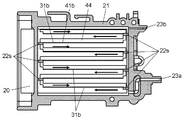
- the heat exchanger 10 has, for example, a rectangular flat plate shape in a casing 23 including a first casing member 21 and a second casing member 22 having a water inlet 23 a and a water outlet 23 b.
- the heater 20 (see FIG. 16), the first flow path forming member 41a, and the second flow path forming member 41b are housed.
- the heater 20 is comprised from the ceramic heater made from ceramics, for example.
- the 1st casing member 21 and the 2nd casing member 22 are comprised by the product made from the reinforced ABS resin which compounded the glass fiber in ABS resin, for example.
- the 1st casing member 21 is arrange
- the second casing member 22 is disposed to face the second heat transfer surface 20 b of the heater 20.
- one surface of the first flow path forming member 41a facing the inner wall surface 30a of the first casing member 21 has a spring property, such as a metal such as a stainless steel plate.
- the 1st partition rib 31a comprised from a board is provided on one surface of the second flow path forming member 41b facing the inner wall surface 40a of the second casing member 22 .
- a second partition rib 31b having a spring property and made of a metal plate such as a stainless steel plate is provided on one surface of the second flow path forming member 41b facing the inner wall surface 40a of the second casing member 22 .
- the 1st partition rib 31a and the 2nd partition rib 31b are formed by bending several places, for example in circular arc shape so that the heat exchange flow path 25 demonstrated below may be formed.
- spring property is provided to the first partition rib 31a and the second partition rib 31b.
- the heat exchange flow path 25 makes the flat part 44 of the other surface of the 1st flow path formation member 41a closely_contact
- a wall-like flange portion 32 extending by a predetermined dimension toward the direction close to the second casing member 22 is provided at the peripheral portion of the base portion 30 of the first casing member 21. It is installed around.
- An engaging groove 33 that circulates along the flange portion 32 is formed at the tip of the flange portion 32.
- a wall-like flange portion 42 is provided around the periphery of the base portion 40 of the second casing member 22 so as to extend by a predetermined dimension in a direction away from the first casing member 21.
- An engagement protrusion 43 that is folded back toward the first casing member 21 and circulates along the flange portion 42 is formed at the distal end portion of the flange portion 42.
- the inner wall surface 30a of the first casing member 21 is externally fitted to the second casing member 22 so as to face the inner wall surface 40a of the second casing member 22 and enclose the heater 20.
- the flange portion 32 of the first casing member 21 is externally fitted to the flange portion 42 of the second casing member 22.
- the engaging protrusion 43 of the second casing member 22 is inserted into the engaging groove 33 of the first casing member 21.
- the first casing member 21 and the second casing member 22 are fixed by welding the engaging protrusion 43 and the engaging groove 33 by, for example, ultrasonic welding, and the casing 23 is formed. Thereby, the 1st casing member 21 and the 2nd casing member 22 are joined fluid-tightly.
- a liquid such as tap water is provided in the heat exchanger 10 from a water inlet 23 a provided at the lower end of the casing 23 in the X direction and connected to an external water supply facility. Injected.
- the liquid injected from the water inlet 23 a of the casing 23 passes through the meandering heat exchange channel 25.
- the liquid flowing through the heat exchange channel 25 is heated to an appropriate temperature (for example, 40 ° C.) by the heater 20 and flows out from the water outlet 23b while passing from the inlet side channel 25a to the outlet side channel 25b.
- the liquid heated to appropriate temperature is supplied to the washing
- the heat exchanger 10 and the sanitary washing device 1 including the heat exchanger 10 according to the present embodiment are configured.
- the heat exchange flow path 25 is formed by contacting the tip 45 of 31b with almost no gap. Thereby, the heat exchange flow path 25 is provided via the gap between the tip 45 of the first partition rib 31a and the second partition rib 31b and the inner wall surface 30a of the first casing member 21 and the inner wall surface 40a of the second casing member 22.
- the leakage flow of the liquid flowing between them can be prevented, and the liquid can be passed through the heat exchanger 10 in a state where forced convection heat exchange is not hindered.
- local boiling on the surface of the heater 20 can be suppressed and the surface temperature of the heater 20 can be lowered.
- the heat exchanger 10 excellent in the stable heat exchange performance and scale resistance is realizable.
- the first flow path forming member 41a and the second flow path forming member 41b are configured by metal plates.
- the first heat transfer surface 20a and the second heat transfer surface 20b of the heater 20 and the flat portions 44 of the first flow path forming member 41a and the second flow path forming member 41b are in close contact with each other.
- the heat of the heater 20 is transmitted from the flat portions 44 of the first flow path forming member 41a and the second flow path forming member 41b to the first partition rib 31a and the second partition rib 31b with a high heat transfer rate. .
- the first partition rib 31a and the second partition rib 31b of the first channel forming member 41a and the second channel forming member 41b increase the heat transfer area to the water flowing through the heat exchange channel 25. Therefore, the heat of the heater 20 can be effectively transferred to the water.
- the heat on the surface of the heater 20 that is generated when the partition rib made of the conventional resin material is brought into contact is prevented from being heated to a local high temperature, and the adhesion of the scale and the adhesion of the scale are prevented. Can prevent the heater from being damaged.
- the heat exchanger 10 that has a high heat transfer rate to a liquid such as water and can maintain excellent heat exchange efficiency over a long period of time can be realized.
- the first partition rib 31a of the first flow path forming member 41a and the second partition rib 31b of the second flow path forming member 41b have spring properties
- the flat part 44 of the 1st partition rib 31a and the 2nd partition rib 31b has the structure which closely_contact
- FIG. Therefore, even if the shapes of the heaters 20 and the casing 23 vary, the flat portions 44 of the first partition rib 31a and the second partition rib 31b are connected to the first heat transfer surface 20a and the second heat transfer surface 20b of the heater 20. And can be securely attached.
- the bending of the first partition rib 31a and the second partition rib 31b having spring properties can prevent concentration of load stress on the closely contacting heater 20.
- abutted to the inner wall surface 30a of the 1st casing member 21 and the inner wall surface 40a of the 2nd casing member 22 is formed.
- the first partition rib 31a of the member 41a and the second partition rib 31b of the second channel forming member 41b are configured by two meandering channels extending from the water inlet 23a to the water outlet 23b of the casing 23. .
- the heat of the heater 20 flows from the flat portions 44 of the first flow path forming member 41a and the second flow path forming member 41b that are in close contact with the first heat transfer surface 20a and the second heat transfer surface 20b.
- the heat is conducted to the first partition rib 31a of the forming member 41a and the second partition rib 31b of the second flow path forming member 41b. Thereby, the heat of the heater 20 is transferred to the wash water flowing through the heat exchange flow path 25 in contact with the first heat transfer surface 20a, the second heat transfer surface 20b, the first partition rib 31a, and the second partition rib 31b. Can heat. As a result, it is possible to realize heat exchange with high heat efficiency and almost no heat loss. Moreover, since both the front and back surfaces of the heater 20 can be used as heat transfer surfaces, the heat exchanger 10 can be configured in a small size and a compact size.
- the cross-sectional area of the flow path is small and the length of the flow path can be increased. For this reason, when washing water having the same flow rate per unit time flows, the flow velocity can be increased by reducing the cross-sectional area of the flow path. And the thickness of the boundary layer between the surface of the heater 20 and the cleaning water can be made thinner. Thereby, while being able to improve the heat transfer rate of the heat exchanger 10, the surface temperature of the heater 20 can be lowered more. As a result, the local boiling phenomenon can be further suppressed, and scale generation and adhesion can be more effectively prevented.
- the heat exchanger 10 is small and stable, has excellent heat exchange performance and scale resistance, and has a long life.
- the sanitary washing device 1 that can be easily installed in a narrow toilet space can be realized.
- the cleaning nozzle from being clogged with scale fragments.
- the sanitary washing device 1 that can be used for a long period of time can be realized particularly in hard water areas.
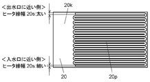
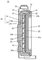
- FIG. 6 is a plan view showing an example of a printing pattern of the heating resistor formed on the heater of the heat exchanger shown in FIG.
- the heater 20 is composed of a ceramic heater in which a heating resistor is formed on a ceramic base 20k made of, for example, aluminum oxide (Al 2 O 3 ).
- the heating resistor is configured by a printing pattern 20p having a predetermined heater line width 20s formed by printing a paste containing tungsten, molybdenum, manganese, or the like.
- the printed pattern 20p constituting the heater wire of the heating resistor is such that the heater wire width 20s is narrow in the portion of the heater 20 near the water inlet 23a of the heat exchanger 10 and the heater 20 near the water outlet 23b.
- the heater line width 20s is configured so as to gradually increase, for example.
- the resistance of the heating resistor is reduced by reducing the heater line width 20s of the printed pattern 20p constituting the heater wire of the heating resistor toward the side closer to the water inlet 23a of the heater 20 (for example, the lower side in FIG. 2).
- the heat density is increased by increasing the value.
- the resistance value of the heating resistor is lowered and the heating density is lowered.
- the heat generation density of the portion facing the outlet-side channel 25b on the side close to the water outlet 23b of the heat exchanger 10 is the heat generation of the portion facing the inlet-side channel 25a on the side close to the inlet 23a. It is comprised so that it may become lower than a density.
- the liquid flowing in from the water inlet 23a of the casing 23 flows through the heat exchange flow path 25 formed meandering on the surface of the heater 20, and the first heat transfer surface 20a and the second heat transfer surface of the heater 20 Heated by 20b. And the temperature of the inflowing liquid rises as it approaches the water outlet 23b. At this time, the surface temperature of the heater 20 facing the heat exchange flow path 25 on the side of the casing 23 near the water inlet 23 a tends to become high due to the high heat generation density of the heater 20. However, much of the heat of the heater 20 is taken away by the unheated low-temperature liquid flowing from the water inlet 23a of the casing 23.
- the value of the subcool (the degree of cooling with respect to the boiling temperature of water) is large, and the heat transfer rate transmitted from the heater 20 to the liquid is increased. Therefore, even if the heat generation density of the heater 20 on the side close to the water inlet 23a of the casing 23 is increased, the temperature is not high enough to cause a local boiling phenomenon.
- the surface temperature of the heater 20 facing the heat exchange passage 25 on the side of the casing 23 near the water outlet 23b tends to be higher than that on the side near the water inlet 23a.
- the fluid that contacts the first heat transfer surface 20 a and the second heat transfer surface 20 b of the heater 20 is already heated while flowing through the heat exchanger 10. For this reason, less heat is taken away from the surface of the heater 20 by the liquid. That is, the value of the subcool becomes small.
- the heater 20 sets the heat generation density on the side near the water outlet 23b to be smaller than the heat generation density on the inlet side flow path 25a side near the water inlet 23a. Therefore, the temperature of the liquid that has flowed through the outlet side flow path 25b on the side close to the water outlet 23b of the heat exchanger 10 does not become high enough to cause a local boiling phenomenon.
- the heat generation density distribution of the heater 20 shows that the vicinity of the heat exchange flow path 25 near the water outlet 23b is closer to the heat exchange flow path 25 near the water inlet 23a. Is also configured to be smaller. Therefore, the heat flux of the heat exchanger 10 is high at a location where the heat generation density of the heater 20 is high, and is low at a location where the heat generation density is low. Thereby, the temperature of the first heat transfer surface 20a and the second heat transfer surface 20b of the heater 20 can be made uniform. As a result, adhesion of scale due to a local increase in the temperature of the surface of the heater 20 can be suppressed.
- the heat of the heater 20 is transferred to a liquid such as tap water flowing in contact with the front and back first heat transfer surfaces 20a and 20b. it can. Thereby, heat exchange with high thermal efficiency with almost no heat dissipation loss can be performed.
- the first heat transfer surface 20a and the second heat transfer surface 20b on the front and back of the heater 20 as heat transfer surfaces, a smaller and more compact heat exchanger 10 can be realized.
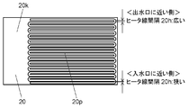
- FIG. 7 is a plan view showing another example of the print pattern of the heating resistor formed on the heater of the heat exchanger shown in FIG.
- description is abbreviate
- the adjacent heater line interval 20h is narrow in the portion near the water inlet 23a of the heater 20, and the heater line interval 20h is close in the portion close to the water outlet 23b. It differs from the heater 20 shown in FIG.
- the heater line interval 20h of the print pattern 20p having a uniform width constituting the heater wire of the heating resistor is narrower toward the side closer to the water inlet 23a of the heat exchanger 10 of the heater 20 (for example, the lower side in FIG. 2).
- the heat generation density of the heating resistor is increased.
- the heater line interval 20h of the printed pattern 20p toward the side closer to the water outlet 23b for example, the upper side in FIG. 2
- the heating line width is changed by changing the heater line width 20s described above, scale generation and adhesion can be prevented, and cracking of the ceramic heater can be prevented to achieve long life and high reliability heat exchange.
- the vessel 10 can be realized.
- first partition rib 31a of the first flow path forming member 41a and the second partition rib 31b of the second flow path forming member 41b of the heat exchanger according to the present embodiment will be described below with reference to FIGS. Will be described.
- the second partition rib 31b of the second flow path forming member 41b will be described as an example, but the same applies to the first partition rib 31a of the first flow path forming member 41a.
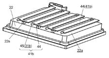
- FIG. 8 is a perspective view showing a state in which the tip of the second partition rib of the heat exchanger shown in FIG. 4 is in contact with the inner wall surface of the second casing member.
- FIG. 9 is a perspective view showing another example of the shape of the second partition rib of the heat exchanger according to the embodiment of the present invention.
- the second flow path forming member 41b is composed of a second partition rib 31b and a flat portion 44.
- the second partition rib 31b has, for example, a tip portion 45 and a cut-and-raised portion having an arcuate cross section. 45a.
- the cut-and-raised portion 45a of the second partition rib 31b connected from the flat portion 44 of the second flow path forming member 41b to the arcuate tip portion 45 is inclined at a non-perpendicular angle, for example, about 45 to 70 degrees. It is preferable to form them.
- the second partition rib 31b of the second flow path forming member 41b may be constituted by, for example, a substantially square shape (including a square shape) in cross section. At this time, the bent portion of the substantially rectangular second partition rib 31b is bent, so that the second partition rib 31b can be provided with a spring property.
- the tip 45 of the second partition rib 31b can be brought into contact with the inner wall surface 40a of the second casing member 22 by absorbing variations in the shape of the member such as the casing and the heater.
- the gap between the tip 45 of the second partition rib 31b and the inner wall surface 40a of the second casing member 22 can be eliminated.
- tip part 45 of the 2nd partition rib 31b can be made to contact
- the relationship between the flow rate (Qmain) flowing through the heat exchange channel in the heat exchanger of the present embodiment and the flow rate (Qleak) of the leakage channel flowing through the partition ribs between the heat exchange channels is expressed as The simulation was performed by changing the gap Hc between the tip of the rib and the heater.
- the said simulation is performed about the case where the flow rate of 500 cc / min is flowed in the heat exchanger by the structure which changed the combination of the shape parameter shown in FIG. 8 by four types.
- the heat exchange flow path 25 formed by the second partition rib 31b of the second flow path forming member 41b will be described as an example.
- the heat exchange flow path 25 is formed by the first partition rib 31a of the first flow path forming member 41a. It goes without saying that the same applies to the heat exchange flow path 25.
- FIG. 10 is a graph showing a result of simulating the influence of the gap Hc when the rib pitch P is 14 mm and the rib height H1 is 1.9 mm.
- FIG. 11 is a graph showing a result of simulating the influence of the gap Hc when the rib pitch P is 7 mm and the rib height H1 is 1.9 mm.
- FIG. 12 is a graph showing a result of simulating the influence of the gap Hc when the rib pitch P is 3.5 mm and the rib height H1 is 1.9 mm.
- FIG. 13 is a graph showing a result of simulating the influence of the gap Hc when the rib pitch P is 3.5 mm and the rib height H1 is 0.95 mm.
- the flow rate of the heat exchange channel 25 that is a flow rate range that is normally used is 0.16 m / sec, in the case of FIG. 11, the flow rate is 0.32 m / sec, and in the case of FIG. In the case of FIG. 13 at 0.64 m / sec, the flow velocity corresponds to 1.25 m / sec.
- the gap Hc is most preferably 0 mm. However, it can be seen that if the gap Hc is 0.15 mm or less, the influence of the flow rate of the leakage channel can be suppressed within a predetermined range.
- the flow rate of the leakage flow path through which the leakage flow flows is set to 50 cc / min or less, the flow of the main flow path that mainly contributes to forced convection heat transfer becomes dominant, and the surface temperature of the heater 20 can be lowered. The bubbles generated in the flow path can be effectively eliminated by the flow of the main flow path.
- FIG. 14 is a graph showing the relationship between the gap Hc and the heater wire temperature of the heater in an actual heat exchanger.
- the heat treatment was performed with a rib pitch P of the partition ribs 31 set to 7 mm and a rib height H1 of the partition ribs 31 set to 1.9 mm.
- the heat exchanger 10 was made of a transparent material, and the state of heat exchange between the heater and the liquid was evaluated.
- FIG. 15 is a view showing the relationship between the gap Hc in the actual heat exchanger and the average heat transfer coefficient of the heat exchanger evaluated from the heater wire temperature shown in FIG. At this time, in the drawing, in order to show the state of the liquid flowing in the heat exchanger, the ratio of forced convection heat transfer and boiling heat transfer is schematically shown.
- the first casing member 21 and the second casing member 22, which are resin molded products constituting the outer casing 23 of the heat exchanger, are formed by integral resin molding, the occurrence of warpage during molding, The welding dimensions vary during sonic welding. Therefore, conventionally, it is difficult to set the gap Hc between the tip 45 of the second partition rib 31b and the inner wall surface 40a of the second casing member 22 to 0.15 mm or less, preferably 0 mm to 0.1 mm.
- a metal plate such as a stainless steel plate is cut and raised by, for example, pressing, and bent into, for example, an arc shape, and a plurality of spring properties are provided on one surface.
- the first flow path forming member 41a having the first partition rib 31a and the second flow path forming member 41b having the plurality of second partition ribs 31b are produced.
- the first partition rib 31a of the first flow path forming member 41a and the second partition of the second flow path forming member 41b Insert so that the ribs 31b face each other.
- the first flow path forming member 41a is incorporated in the inner wall surface 30a of the first casing member 21 and the second flow path forming member 41b is incorporated in the inner wall surface 40a of the second casing member 22 in advance. Is made.
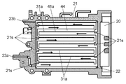
- FIG. 16 is a cross-sectional view taken along line 16-16 of the heat exchanger shown in FIG. 17 is a cross-sectional view of the heat exchanger shown in FIG. 3 taken along line 17-17.
- 18 is a cross-sectional view of the heat exchanger shown in FIG. 3 taken along line 18-18.
- FIG. 19 is a perspective view showing a state in which the first flow path forming member of the heat exchanger shown in FIG. 4 is in close contact with the heater.
- the first flow path is formed so as to coincide with the positions of the side ribs 21s provided corresponding to the first partition ribs 31a.
- the forming member 41a is fitted.
- the side ribs 21 s of the first casing member 21 are not shown because the side ribs 22 s of the second casing member 22 overlap.
- the first flow path forming member 41a is assembled in the first casing member 21.
- the front end portions 45 of the plurality of first partition ribs 31 a formed on the first flow path forming member 41 a are assembled so as to contact the inner wall surface 30 a of the first casing member 21.
- the heat exchange flow path 25 which consists of a meandering flow path as shown by the arrow in FIG. 16 is formed by the inner wall surface 30a of the first casing member 21 and the first partition rib 31a.
- the heater 20 is arranged on the flat portion 44 side of the first partition rib 31a.
- the flat portion 44 of the first partition rib 31 a of the first flow path forming member 41 a is disposed in close contact with the first heat transfer surface 20 a of the heater 20.
- the first partition ribs 31a of the first flow path forming member 41a are arranged at a predetermined rib pitch P and a predetermined rib height H1, and the heat exchange flow path 25 is formed.
- the second flow path is formed so as to coincide with the positions of the side ribs 22 s provided correspondingly to the second partition rib 31 b on the inner peripheral wall surface of the second casing member 22.
- the forming member 41b is fitted.
- the second flow path forming member 41b is assembled in the second casing member 22.
- the front end portions 45 of the plurality of second partition ribs 31 b formed on the second flow path forming member 41 b are assembled so as to contact the inner wall surface 40 a of the second casing member 22.
- the heat exchange flow path 25 which consists of a meandering flow path as shown by the arrow in FIG.
- FIG. 18 is formed by the inner wall surface 40a of the second casing member 22 and the second partition rib 31b. Also in FIG. 18, the side ribs 22 s of the second casing member 22 are not shown because the side ribs 21 s of the first casing member 21 overlap.
- the flat portion 44 of the first partition rib 31a of the first flow path forming member 41a and the flat portion 44 of the second partition rib 31b of the second flow path forming member 41b Place them facing each other.
- the first casing member 21 and the second casing member 22 are, for example, super Weld by sonic welding.
- the engagement groove 33 of the flange portion 32 of the first casing member 21 and the engagement protrusion 43 of the flange portion 42 of the second casing member 22 are welded. And the casing 23 is formed.
- the rib height H1 of the first partition rib 31a and the second partition rib 31b is at least the inner wall surface 30a of the first casing member 21 and the inner wall surface 40a of the second casing member 22 in a state where the casing 23 is formed. It is preferable to provide at a height higher than the contact level.
- the first partition rib 31a and the second partition rib 31b having spring properties are bent, so that the first partition The end portions 45 of the ribs 31 a and the second partition ribs 31 b are in contact with the inner wall surface 30 a of the first casing member 21 and the inner wall surface 40 a of the second casing member 22. That is, when the first partition rib 31a and the second partition rib 31b are bent, the leading end portions 45 of the first partition rib 31a and the second partition rib 31b, the inner wall surface 30a of the first casing member 21, and the second casing member.
- the gap Hc with the inner wall surface 40a of 22 can be almost eliminated.
- the heat exchanger 10 includes the tip 45 of the first partition rib 31a and the tip 45 of the second partition rib 31b, the inner wall surface 30a of the first casing member 21, and the inner wall surface 40a of the second casing member 22.
- the heater 20 and the casing 23 are sealed with a sealing material made of, for example, an O-ring seal or a silicon sealant.
- the heat exchanger 10 of the present embodiment is manufactured.
- the 1st flow path formation member 41a and the 2nd flow path formation member 41b were demonstrated in the example formed by the bending process of the stainless steel plate, it is not restricted to this.
- the first flow path forming member 41a and the second flow path forming member 41b may be made of a thin metal plate having excellent spring properties and thermal conductivity, such as phosphor bronze and beryllium copper.
- the 1st flow path formation member 41a and the 2nd flow path formation member 41b which were excellent in still higher spring property and thermal conductivity are realizable.
- the 1st partition rib 31a and the 2nd partition rib 31b are provided in the 1st flow path formation member 41a and the 2nd flow path formation member 41b, and the two heat exchange flow paths 25 are provided.
- One partition wall 31 of the flow path forming member 41 and one surface of the heater 20 may constitute one heat exchange flow path 25. For example, as shown in FIG.
- a configuration in which the flow path forming member 41 is inserted into the inner wall surface 30 a of the first casing member 21 and the heater 20 is provided on the inner wall surface 40 a of the second casing member 22 may be employed.
- the one end portion 45 of the partition rib 31 of the flow path forming member 41 and the inner wall surface 30a of the first casing member 21 may be brought into contact with each other to form one heat exchange flow path 25.
- the heater 20 is provided with a heating resistor on the surface facing the flat portion 44 of the partition rib 31 of the flow path forming member 41 including at least the partition rib 31.
- the liquid can be made to flow uniformly through the heat exchange channel 25, the occurrence of local boiling on the surface of the heater 20 can be suppressed, and the surface temperature of the heater 20 can be lowered. As a result, a more compact and compact heat exchanger 10 having excellent stable heat exchange performance and scale resistance can be realized.
- the sanitary washing device 1 can be realized that has excellent heat exchange performance and scale resistance, has a long life, is small, and can be easily installed in a narrow toilet space.
- the casing having the water inlet and the water outlet, the heater contained in the casing and containing the heating resistor, and the fluid flowing in from the water inlet are discharged from the water outlet.
- the heat exchange flow path is configured by bringing the other surface of the flow path forming member into close contact with the heat transfer surface of the heater and abutting the tip end portion of the partition rib of the flow path forming member on the inner wall surface of the casing. .
- the flow path forming member includes a first flow path forming member having a first partition rib on one surface and a second flow path formation having a second partition rib on one surface. It consists of members.
- the heat exchange channel closely contacts the other surface of the first channel forming member and the other surface of the second channel forming member to the heat transfer surfaces on the front and back sides of the heater, Two meandering channels are formed extending from the water inlet to the water outlet of the casing by abutting the tip of the one partition rib and the tip of the second partition rib of the second channel forming member on the inner wall surface of the casing. To do.
- the heat transfer rate of the heat exchanger can be improved and the temperature of the heater surface can be further lowered.
- the local boiling phenomenon of washing water can be further suppressed, and scale generation and adhesion can be more effectively prevented.
- the flow path forming member is formed of any one of a stainless plate, phosphor bronze and beryllium copper.
- the heater has a heat generation density facing the heat exchange flow path near the water outlet smaller than a heat generation density facing the heat exchange flow path near the water inlet.
- the heater is a ceramic heater comprising a ceramic base, a heating resistor made of a resistor formed on the ceramic base with a print pattern having a predetermined heater line width, and an electrode. Consists of.
- the heater line width of the heater print pattern may have a configuration in which the portion closer to the water outlet is thicker than the portion closer to the water inlet.
- the heater has a feature that the heat capacity is smaller than that of metal, but on the other hand, even if a ceramic heater that is easily cracked is used, it is possible to prevent cracking due to the difference in heating temperature of the heater. As a result, a long-life and highly reliable heat exchanger can be realized.
- the gap between the printed pattern lines of the heater faces the heat exchange channel closer to the water outlet than the portion facing the heat exchange channel closer to the water inlet.
- the portion that has been made may have a wider configuration.
- This configuration makes it possible to increase the amount of heat generated in the portion facing the heat exchange flow path on the side close to the water inlet where the gaps between the printed pattern lines are narrow, that is, increase the heat generation density.
- the amount of heat generated in the portion facing the heat exchange channel on the side close to the water outlet where the gaps between the printed pattern lines are wide can be reduced, that is, the heat generation density can be reduced.
- the above heat exchanger is provided.
- the present invention does not cause local boiling on the heater surface, and lowers the temperature of the heater surface so that it has excellent stable heat exchange performance and scale resistance, and is applied to a heat exchanger having a flat plate heater. Can do.
Landscapes
- Engineering & Computer Science (AREA)
- Chemical & Material Sciences (AREA)
- Health & Medical Sciences (AREA)
- Public Health (AREA)
- Thermal Sciences (AREA)
- Combustion & Propulsion (AREA)
- Mechanical Engineering (AREA)
- General Engineering & Computer Science (AREA)
- Physics & Mathematics (AREA)
- Ceramic Engineering (AREA)
- Molecular Biology (AREA)
- Epidemiology (AREA)
- Life Sciences & Earth Sciences (AREA)
- Hydrology & Water Resources (AREA)
- Water Supply & Treatment (AREA)
- Bidet-Like Cleaning Device And Other Flush Toilet Accessories (AREA)
- Instantaneous Water Boilers, Portable Hot-Water Supply Apparatuses, And Control Of Portable Hot-Water Supply Apparatuses (AREA)
Abstract
L'invention porte sur un échangeur de chaleur (10), lequel échangeur comporte une enceinte (23), un élément chauffant (20), un passage d'écoulement d'échange de chaleur (25) et un élément de formation de passage d'écoulement (41), qui comprend une plaque métallique qui comporte une nervure de séparation (31) sur une surface de l'élément de formation de passage d'écoulement (41). Le passage d'écoulement d'échange de chaleur (25) est formé de telle manière que l'autre surface de l'élément de formation de passage d'écoulement (41) est amenée à être en contact étroit avec la surface de transfert de chaleur de l'élément chauffant (20), et de telle manière que l'extrémité avant (45) de la nervure de séparation (31) de l'élément de formation de passage d'écoulement (41) est en contact avec les surfaces de paroi interne (30a, 40a) de l'enceinte (23). En résultat de cette configuration, l'écoulement de fuite entre l'élément chauffant (20) et l'extrémité avant (45) de la nervure de séparation (31) est empêché, empêchant un échange de chaleur par convexion forcée d'être gêné. Par conséquent, l'échangeur de chaleur (10) a des performances d'échange de chaleur constantes et d'excellentes propriétés anti-tartre.
Applications Claiming Priority (2)
| Application Number | Priority Date | Filing Date | Title |
|---|---|---|---|
| JP2012157191A JP5945722B2 (ja) | 2012-07-13 | 2012-07-13 | 熱交換器とそれを備えた衛生洗浄便座 |
| JP2012-157191 | 2012-07-13 |
Publications (1)
| Publication Number | Publication Date |
|---|---|
| WO2014010142A1 true WO2014010142A1 (fr) | 2014-01-16 |
Family
ID=49915631
Family Applications (1)
| Application Number | Title | Priority Date | Filing Date |
|---|---|---|---|
| PCT/JP2013/001287 Ceased WO2014010142A1 (fr) | 2012-07-13 | 2013-03-04 | Échangeur de chaleur et dispositif de nettoyage sanitaire le comportant |
Country Status (2)
| Country | Link |
|---|---|
| JP (1) | JP5945722B2 (fr) |
| WO (1) | WO2014010142A1 (fr) |
Cited By (2)
| Publication number | Priority date | Publication date | Assignee | Title |
|---|---|---|---|---|
| CN112050866A (zh) * | 2020-09-22 | 2020-12-08 | 芜湖乐佳电器有限公司 | 一种智能马桶即热模块用带温控感知组件的流量计 |
| WO2021057044A1 (fr) * | 2019-09-27 | 2021-04-01 | 厦门科牧智能技术有限公司 | Dispositif de chauffage, dispositif d'alimentation en eau sanitaire, et dispositif de nettoyage sanitaire |
Families Citing this family (1)
| Publication number | Priority date | Publication date | Assignee | Title |
|---|---|---|---|---|
| WO2024034905A1 (fr) * | 2022-08-12 | 2024-02-15 | 주식회사 경동나비엔 | Échangeur de chaleur et appareil de chauffage d'eau le comprenant |
Citations (2)
| Publication number | Priority date | Publication date | Assignee | Title |
|---|---|---|---|---|
| WO2011027576A1 (fr) * | 2009-09-07 | 2011-03-10 | パナソニック株式会社 | Echangeur de chaleur |
| JP2011214788A (ja) * | 2010-03-31 | 2011-10-27 | Toto Ltd | 熱交換器およびそれを備えた衛生洗浄装置 |
Family Cites Families (1)
| Publication number | Priority date | Publication date | Assignee | Title |
|---|---|---|---|---|
| EP1731849A4 (fr) * | 2003-12-10 | 2013-09-18 | Panasonic Corp | Echangeur thermique et dispositif d'epuration |
-
2012
- 2012-07-13 JP JP2012157191A patent/JP5945722B2/ja not_active Expired - Fee Related
-
2013
- 2013-03-04 WO PCT/JP2013/001287 patent/WO2014010142A1/fr not_active Ceased
Patent Citations (2)
| Publication number | Priority date | Publication date | Assignee | Title |
|---|---|---|---|---|
| WO2011027576A1 (fr) * | 2009-09-07 | 2011-03-10 | パナソニック株式会社 | Echangeur de chaleur |
| JP2011214788A (ja) * | 2010-03-31 | 2011-10-27 | Toto Ltd | 熱交換器およびそれを備えた衛生洗浄装置 |
Cited By (3)
| Publication number | Priority date | Publication date | Assignee | Title |
|---|---|---|---|---|
| WO2021057044A1 (fr) * | 2019-09-27 | 2021-04-01 | 厦门科牧智能技术有限公司 | Dispositif de chauffage, dispositif d'alimentation en eau sanitaire, et dispositif de nettoyage sanitaire |
| US12559925B2 (en) | 2019-09-27 | 2026-02-24 | Komoo Intelligent Technology Co., Ltd. | Heating device, sanitary water supply device, and sanitary cleaning device |
| CN112050866A (zh) * | 2020-09-22 | 2020-12-08 | 芜湖乐佳电器有限公司 | 一种智能马桶即热模块用带温控感知组件的流量计 |
Also Published As
| Publication number | Publication date |
|---|---|
| JP2014020606A (ja) | 2014-02-03 |
| JP5945722B2 (ja) | 2016-07-05 |
Similar Documents
| Publication | Publication Date | Title |
|---|---|---|
| WO2013150696A1 (fr) | Échangeur de chaleur et dispositif de nettoyage hygiénique le comportant | |
| TW201114398A (en) | Heat exchanger | |
| WO2014010142A1 (fr) | Échangeur de chaleur et dispositif de nettoyage sanitaire le comportant | |
| JP5534117B2 (ja) | 熱交換器の製造方法 | |
| JP2007524068A (ja) | 液体を加熱するためのデバイスおよび方法、と基本構造 | |
| KR20030010676A (ko) | 전기식 온수기·액체가열기·증기발생기 | |
| KR20150034919A (ko) | 순간 온수화를 위한 가열장치 | |
| JP2000154938A (ja) | 瞬間加熱温水装置 | |
| US10859325B2 (en) | Heat exchanger | |
| KR101399717B1 (ko) | 위생 세정 장치 | |
| CN218217708U (zh) | 厚膜发热体及加热装置 | |
| JP2012233677A (ja) | 熱交換器 | |
| CN118274457A (zh) | 厚膜加热器基板、厚膜加热器基板成型方法和厚膜加热器 | |
| US20120148220A1 (en) | Heat exchanger | |
| CN113038800B (zh) | 液冷散热结构 | |
| US20120201525A1 (en) | Heating apparatus | |
| JP3715785B2 (ja) | 液体加熱装置 | |
| JPH0132905B2 (fr) | ||
| JPH116651A (ja) | 流水加熱装置 | |
| JP5786129B2 (ja) | 熱交換器 | |
| CN221961985U (zh) | 一种双向错齿式加热板 | |
| CN107830623A (zh) | 外冷内热的流体加热器 | |
| KR100745455B1 (ko) | 보조히터 및 이를 구비하는 온수히터 | |
| KR20080023446A (ko) | 반도체 제조를 위한 유체가열용 인라인히터유닛 | |
| KR20090027712A (ko) | 복층형 태양열 집열판 |
Legal Events
| Date | Code | Title | Description |
|---|---|---|---|
| 121 | Ep: the epo has been informed by wipo that ep was designated in this application |
Ref document number: 13816115 Country of ref document: EP Kind code of ref document: A1 |
|
| NENP | Non-entry into the national phase |
Ref country code: DE |
|
| 122 | Ep: pct application non-entry in european phase |
Ref document number: 13816115 Country of ref document: EP Kind code of ref document: A1 |