WO2014010199A1 - ロータリ圧縮機 - Google Patents
ロータリ圧縮機 Download PDFInfo
- Publication number
- WO2014010199A1 WO2014010199A1 PCT/JP2013/004107 JP2013004107W WO2014010199A1 WO 2014010199 A1 WO2014010199 A1 WO 2014010199A1 JP 2013004107 W JP2013004107 W JP 2013004107W WO 2014010199 A1 WO2014010199 A1 WO 2014010199A1
- Authority
- WO
- WIPO (PCT)
- Prior art keywords
- oil reservoir
- oil
- rotary compressor
- cylinder
- convection
- Prior art date
- Legal status (The legal status is an assumption and is not a legal conclusion. Google has not performed a legal analysis and makes no representation as to the accuracy of the status listed.)
- Ceased
Links
Images





Classifications
-
- F—MECHANICAL ENGINEERING; LIGHTING; HEATING; WEAPONS; BLASTING
- F04—POSITIVE - DISPLACEMENT MACHINES FOR LIQUIDS; PUMPS FOR LIQUIDS OR ELASTIC FLUIDS
- F04C—ROTARY-PISTON, OR OSCILLATING-PISTON, POSITIVE-DISPLACEMENT MACHINES FOR LIQUIDS; ROTARY-PISTON, OR OSCILLATING-PISTON, POSITIVE-DISPLACEMENT PUMPS
- F04C23/00—Combinations of two or more pumps, each being of rotary-piston or oscillating-piston type, specially adapted for elastic fluids; Pumping installations specially adapted for elastic fluids; Multi-stage pumps specially adapted for elastic fluids
- F04C23/008—Hermetic pumps
-
- F—MECHANICAL ENGINEERING; LIGHTING; HEATING; WEAPONS; BLASTING
- F04—POSITIVE - DISPLACEMENT MACHINES FOR LIQUIDS; PUMPS FOR LIQUIDS OR ELASTIC FLUIDS
- F04C—ROTARY-PISTON, OR OSCILLATING-PISTON, POSITIVE-DISPLACEMENT MACHINES FOR LIQUIDS; ROTARY-PISTON, OR OSCILLATING-PISTON, POSITIVE-DISPLACEMENT PUMPS
- F04C29/00—Component parts, details or accessories of pumps or pumping installations, not provided for in groups F04C18/00 - F04C28/00
- F04C29/02—Lubrication; Lubricant separation
- F04C29/028—Means for improving or restricting lubricant flow
-
- F—MECHANICAL ENGINEERING; LIGHTING; HEATING; WEAPONS; BLASTING
- F04—POSITIVE - DISPLACEMENT MACHINES FOR LIQUIDS; PUMPS FOR LIQUIDS OR ELASTIC FLUIDS
- F04C—ROTARY-PISTON, OR OSCILLATING-PISTON, POSITIVE-DISPLACEMENT MACHINES FOR LIQUIDS; ROTARY-PISTON, OR OSCILLATING-PISTON, POSITIVE-DISPLACEMENT PUMPS
- F04C18/00—Rotary-piston pumps specially adapted for elastic fluids
- F04C18/30—Rotary-piston pumps specially adapted for elastic fluids having the characteristics covered by two or more of groups F04C18/02, F04C18/08, F04C18/22, F04C18/24, F04C18/48, or having the characteristics covered by one of these groups together with some other type of movement between co-operating members
- F04C18/34—Rotary-piston pumps specially adapted for elastic fluids having the characteristics covered by two or more of groups F04C18/02, F04C18/08, F04C18/22, F04C18/24, F04C18/48, or having the characteristics covered by one of these groups together with some other type of movement between co-operating members having the movement defined in group F04C18/08 or F04C18/22 and relative reciprocation between the co-operating members
- F04C18/356—Rotary-piston pumps specially adapted for elastic fluids having the characteristics covered by two or more of groups F04C18/02, F04C18/08, F04C18/22, F04C18/24, F04C18/48, or having the characteristics covered by one of these groups together with some other type of movement between co-operating members having the movement defined in group F04C18/08 or F04C18/22 and relative reciprocation between the co-operating members with vanes reciprocating with respect to the outer member
- F04C18/3562—Rotary-piston pumps specially adapted for elastic fluids having the characteristics covered by two or more of groups F04C18/02, F04C18/08, F04C18/22, F04C18/24, F04C18/48, or having the characteristics covered by one of these groups together with some other type of movement between co-operating members having the movement defined in group F04C18/08 or F04C18/22 and relative reciprocation between the co-operating members with vanes reciprocating with respect to the outer member the inner and outer member being in contact along one line or continuous surfaces substantially parallel to the axis of rotation
-
- F—MECHANICAL ENGINEERING; LIGHTING; HEATING; WEAPONS; BLASTING
- F04—POSITIVE - DISPLACEMENT MACHINES FOR LIQUIDS; PUMPS FOR LIQUIDS OR ELASTIC FLUIDS
- F04C—ROTARY-PISTON, OR OSCILLATING-PISTON, POSITIVE-DISPLACEMENT MACHINES FOR LIQUIDS; ROTARY-PISTON, OR OSCILLATING-PISTON, POSITIVE-DISPLACEMENT PUMPS
- F04C18/00—Rotary-piston pumps specially adapted for elastic fluids
- F04C18/30—Rotary-piston pumps specially adapted for elastic fluids having the characteristics covered by two or more of groups F04C18/02, F04C18/08, F04C18/22, F04C18/24, F04C18/48, or having the characteristics covered by one of these groups together with some other type of movement between co-operating members
- F04C18/34—Rotary-piston pumps specially adapted for elastic fluids having the characteristics covered by two or more of groups F04C18/02, F04C18/08, F04C18/22, F04C18/24, F04C18/48, or having the characteristics covered by one of these groups together with some other type of movement between co-operating members having the movement defined in group F04C18/08 or F04C18/22 and relative reciprocation between the co-operating members
- F04C18/356—Rotary-piston pumps specially adapted for elastic fluids having the characteristics covered by two or more of groups F04C18/02, F04C18/08, F04C18/22, F04C18/24, F04C18/48, or having the characteristics covered by one of these groups together with some other type of movement between co-operating members having the movement defined in group F04C18/08 or F04C18/22 and relative reciprocation between the co-operating members with vanes reciprocating with respect to the outer member
- F04C18/3562—Rotary-piston pumps specially adapted for elastic fluids having the characteristics covered by two or more of groups F04C18/02, F04C18/08, F04C18/22, F04C18/24, F04C18/48, or having the characteristics covered by one of these groups together with some other type of movement between co-operating members having the movement defined in group F04C18/08 or F04C18/22 and relative reciprocation between the co-operating members with vanes reciprocating with respect to the outer member the inner and outer member being in contact along one line or continuous surfaces substantially parallel to the axis of rotation
- F04C18/3564—Rotary-piston pumps specially adapted for elastic fluids having the characteristics covered by two or more of groups F04C18/02, F04C18/08, F04C18/22, F04C18/24, F04C18/48, or having the characteristics covered by one of these groups together with some other type of movement between co-operating members having the movement defined in group F04C18/08 or F04C18/22 and relative reciprocation between the co-operating members with vanes reciprocating with respect to the outer member the inner and outer member being in contact along one line or continuous surfaces substantially parallel to the axis of rotation the surfaces of the inner and outer member, forming the working space, being surfaces of revolution
-
- F—MECHANICAL ENGINEERING; LIGHTING; HEATING; WEAPONS; BLASTING
- F04—POSITIVE - DISPLACEMENT MACHINES FOR LIQUIDS; PUMPS FOR LIQUIDS OR ELASTIC FLUIDS
- F04C—ROTARY-PISTON, OR OSCILLATING-PISTON, POSITIVE-DISPLACEMENT MACHINES FOR LIQUIDS; ROTARY-PISTON, OR OSCILLATING-PISTON, POSITIVE-DISPLACEMENT PUMPS
- F04C29/00—Component parts, details or accessories of pumps or pumping installations, not provided for in groups F04C18/00 - F04C28/00
- F04C29/04—Heating; Cooling; Heat insulation
-
- F—MECHANICAL ENGINEERING; LIGHTING; HEATING; WEAPONS; BLASTING
- F04—POSITIVE - DISPLACEMENT MACHINES FOR LIQUIDS; PUMPS FOR LIQUIDS OR ELASTIC FLUIDS
- F04C—ROTARY-PISTON, OR OSCILLATING-PISTON, POSITIVE-DISPLACEMENT MACHINES FOR LIQUIDS; ROTARY-PISTON, OR OSCILLATING-PISTON, POSITIVE-DISPLACEMENT PUMPS
- F04C2240/00—Components
- F04C2240/30—Casings or housings
-
- F—MECHANICAL ENGINEERING; LIGHTING; HEATING; WEAPONS; BLASTING
- F04—POSITIVE - DISPLACEMENT MACHINES FOR LIQUIDS; PUMPS FOR LIQUIDS OR ELASTIC FLUIDS
- F04C—ROTARY-PISTON, OR OSCILLATING-PISTON, POSITIVE-DISPLACEMENT MACHINES FOR LIQUIDS; ROTARY-PISTON, OR OSCILLATING-PISTON, POSITIVE-DISPLACEMENT PUMPS
- F04C2240/00—Components
- F04C2240/80—Other components
- F04C2240/809—Lubricant sump
-
- F—MECHANICAL ENGINEERING; LIGHTING; HEATING; WEAPONS; BLASTING
- F04—POSITIVE - DISPLACEMENT MACHINES FOR LIQUIDS; PUMPS FOR LIQUIDS OR ELASTIC FLUIDS
- F04C—ROTARY-PISTON, OR OSCILLATING-PISTON, POSITIVE-DISPLACEMENT MACHINES FOR LIQUIDS; ROTARY-PISTON, OR OSCILLATING-PISTON, POSITIVE-DISPLACEMENT PUMPS
- F04C23/00—Combinations of two or more pumps, each being of rotary-piston or oscillating-piston type, specially adapted for elastic fluids; Pumping installations specially adapted for elastic fluids; Multi-stage pumps specially adapted for elastic fluids
- F04C23/001—Combinations of two or more pumps, each being of rotary-piston or oscillating-piston type, specially adapted for elastic fluids; Pumping installations specially adapted for elastic fluids; Multi-stage pumps specially adapted for elastic fluids of similar working principle
Definitions
- An airtight container having an oil reservoir; A cylinder, a piston disposed inside the cylinder, a vane that partitions a space formed between the cylinder and the piston into a suction chamber and a compression-discharge chamber, and a suction that guides the working fluid to the suction chamber
- a compression mechanism disposed inside the hermetic container so as to be immersed in oil stored in the oil reservoir, and a discharge port for discharging a working fluid from the compression-discharge chamber;
- a convection suppression unit dividing the oil reservoir into a plurality of parts in the vertical direction; A communication path for communicating the plurality of portions of the oil reservoir with each other; With When a plane that passes through a tangent line between the inner peripheral surface of the cylinder and the outer peripheral surface of the piston when the vane protrudes most toward the central axis of the cylinder and includes the central axis of the cylinder is a reference plane
- a rotary compressor is provided in which the communication path is located on the same side as the discharge port as
- FIG. 1 is a longitudinal sectional view of a rotary compressor according to an embodiment of the present invention.
- Fig. 1 is a cross-sectional view of the rotary compressor shown in Fig. 1 taken along line IIA-IIA.
- Cross section taken along line IIB-IIB of the rotary compressor shown in FIG.
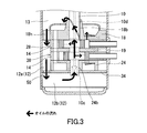
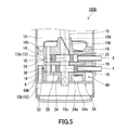
- Partial longitudinal cross-sectional view of the rotary compressor concerning the modification 3 Cross-sectional view of a rotary compressor according to modification 4
- the first aspect of the present disclosure is: An airtight container having an oil reservoir; A cylinder, a piston disposed inside the cylinder, a vane that partitions a space formed between the cylinder and the piston into a suction chamber and a compression-discharge chamber, and a suction that guides the working fluid to the suction chamber
- a compression mechanism disposed inside the hermetic container so as to be immersed in oil stored in the oil reservoir, and a discharge port for discharging a working fluid from the compression-discharge chamber;
- a convection suppression unit dividing the oil reservoir into a plurality of parts in the vertical direction; A communication path for communicating the plurality of portions of the oil reservoir with each other; With When a plane that passes through a tangent line between the inner peripheral surface of the cylinder and the outer peripheral surface of the piston when the vane protrudes most toward the central axis of the cylinder and includes the central axis of the cylinder is a reference plane
- a rotary compressor is provided in which the communication path is located
- the second aspect provides a rotary compressor in addition to the first aspect, wherein the communication path is a communication hole formed in the convection suppressing portion. It is easy to form the communication hole in the convection suppressing portion, which is desirable from the viewpoint of design.
- 3rd aspect provides the rotary compressor in which the said convection suppression part has two or more of the said communication holes in addition to a 2nd aspect. According to such a configuration, there is a possibility that the oil flow can be further suppressed on the same side as the suction port as viewed from the reference plane.
- the rotary compressor is located on the same side as the discharge port as viewed from the reference plane. According to such a configuration, the oil flow is further suppressed on the same side as the suction port as viewed from the reference plane.
- the rotary compressor 100A of this embodiment is a hermetic compressor, and includes a hermetic container 1, a motor 7, a compression mechanism 48, and a shaft 10.
- the compression mechanism 48 includes an upper muffler 33, an upper closing member 18 (upper bearing member), a first compression block 28, an intermediate plate 19, a second compression block 38, a lower closing member 24 (lower bearing member), and a lower end face plate 34. .
- the compression blocks 28 and 38 are sandwiched between the upper closing member 18 (upper bearing member) and the lower closing member 24 (lower bearing member).
- An intermediate plate 19 is disposed between the first compression block 28 and the second compression block 38.
- the motor 7 is disposed above the upper closing member 18 inside the sealed container 1.
- the shaft 10 extends in the vertical direction.
- a compression mechanism 48 is connected to the motor 7 by the shaft 10.
- a terminal 11 for supplying electric power to the motor 7 is provided on the top of the sealed container 1.
- the sealed container 1 has an internal space 13 filled with a refrigerant (working fluid) compressed by the compression mechanism 48.
- An oil reservoir 12 is formed at the bottom of the sealed container 1.
- a suction pipe 3, a suction pipe 4 and a discharge pipe 5 are connected to the sealed container 1.
- the suction pipe 3 passes through the body of the sealed container 1 and connects an accumulator (not shown) and the first compression block 28.
- the suction pipe 4 passes through the trunk of the sealed container 1 and connects the accumulator and the second compression block 38.
- the suction pipes 3 and 4 serve to guide the refrigerant to be compressed from the accumulator to the compression blocks 28 and 38.
- the discharge pipe 5 passes through the upper part of the sealed container 1 and opens into the internal space 13 of the sealed container 1.
- the discharge pipe 5 plays a role of discharging the compressed refrigerant to the outside of the rotary compressor 100A.
- the compression mechanism 48 is arranged inside the sealed container 1 so as to be immersed in the oil stored in the oil reservoir 12.
- the first compression block 28 and the second compression block 38 are arranged in a direction parallel to the rotation axis of the shaft 10.
- the first compression block 28 has a suction port 8a and a discharge port 8b.
- the second compression block 38 has a suction port 8c and a discharge port 8d.
- the refrigerant When the second compression block 38 is moved by the motor 7, the refrigerant is sucked from the suction port 8c, compressed, and discharged from the discharge port 8d.
- the internal space 13 of the sealed container 1 is filled with the refrigerant discharged from the compression blocks 28 and 38.
- the structure of the first compression block 28 is the same as the structure of the second compression block 38.
- the piston 15 is disposed inside the cylinder 14 and is fitted to the first eccentric portion 10a or the second eccentric portion 10b of the shaft 10.
- a working chamber 25 is formed between the inner peripheral surface of the cylinder 14 and the outer peripheral surface of the piston 15.
- a vane groove 26 is formed in the cylinder 14.
- a vane 16 is disposed in the vane groove 26.
- a holding hole 20 that opens from the outer end of the vane groove 26 toward both end faces of the cylinder 14 is formed behind the vane groove 26.
- the spring 17 is disposed in the holding hole 20 and the vane groove 26 so as to push the vane 16 toward the piston 15.
- the tip of the vane 16 is in contact with the outer peripheral surface of the piston 15.
- the working chamber 25 is partitioned by the vane 16, thereby forming a suction chamber 25a and a compression-discharge chamber 25b.
- the vane 16 may be integrated with the piston 15. That is, the piston 15 and the vane 16 may constitute a so-called swing piston.
- the suction port 8a is formed in the cylinder 14.
- the downstream end of the suction pipe 3 is connected to the suction port 8a.
- the suction port 8 a and the suction pipe 3 form a suction path 21 that guides the refrigerant from the outside of the sealed container 1 to the working chamber 25.
- the suction port 8 c is formed in the cylinder 14.
- a downstream end of the suction pipe 4 is connected to the suction port 8c.
- the suction port 8 c and the suction pipe 4 form a suction path 22 that guides the refrigerant from the outside of the sealed container 1 to the working chamber 25.
- the suction paths 21 and 22 are also arranged in a direction parallel to the rotation axis of the shaft 10.
- the vane 16 of the second compression block 38 is disposed at a position (angular position) that coincides with the vane 16 of the first compression block 28 in the circumferential direction of the shaft 10. For this reason, the timing at which the piston 15 of the second compression block 38 is located at the top dead center (the position at which the vane 16 is most retracted) is shifted by 180 degrees from the timing at which the piston 15 of the first compression block 28 is located at the top dead center. Yes.
- a recess 18 a is formed on the upper surface of the upper closing member 18.
- the recess 18 a is located in the vicinity of the vane 16 of the first compression block 28.
- the discharge port 8b extends from the lower surface of the upper closing member 18 to the bottom surface of the recess 18a.
- a discharge valve 29 and a stopper 30 are disposed in the recess 18a.
- the discharge valve 29 opens and closes the discharge port 8b by elastic deformation.
- the stopper 30 regulates the deformation amount of the discharge valve 29.
- An upper muffler 33 is disposed above the upper closing member 18.
- the upper muffler 33 covers the discharge port 8 b together with the space above the upper closing member 18.
- the discharge port 8 b communicates with the internal space 13 of the sealed container 1 through a space covered with the upper muffler 33.
- the oil level of the oil sump 12 is generally located at a height near the lower surface of the upper closing member 18 during operation of the rotary compressor 100A.
- a recess 24 a is formed on the lower surface of the lower closing member 24.
- the recess 24 a is located in the vicinity of the vane 16 of the second compression block 38.
- the discharge port 8d extends from the upper surface of the lower closing member 24 to the bottom surface of the recess 24a.
- a discharge valve 31 and a stopper 32 are disposed in the recess 24a.
- the discharge valve 31 opens and closes the discharge port 8d by elastic deformation.
- the stopper 32 regulates the deformation amount of the discharge valve 31.
- a lower end face plate 34 is disposed below the lower closing member 24. The lower end face plate 34 communicates with the discharge port 8d and closes the space formed in the lower closing member 24 including the recess 24a.
- the lower end face plate 34 extends in a direction perpendicular to the rotation axis of the shaft 10 (radial direction of the shaft 10).
- the outer peripheral surface of the lower end face plate 34 is located farther from the rotation axis of the shaft 10 than the outer peripheral surface of the cylinder 14 in the radial direction of the shaft 10, and is in contact with, for example, the inner peripheral surface of the sealed container 1.
- the shape of the lower end face plate 34 is, for example, a circle in plan view.
- the lower end face plate 34 is provided around the compression mechanism 48 to divide the oil reservoir 12 into a plurality of portions in the vertical direction, and serves as a convection suppressing unit that suppresses convection of oil in the oil reservoir 12.
- the communication hole 50 is formed in the lower end face plate 34. In the radial direction of the shaft 10, the communication hole 50 is located between the inner peripheral surface of the sealed container 1 and the outer peripheral surface of the cylinder 14. Through the communication hole 50, the upper oil reservoir 12a communicates with the lower oil reservoir 12b. 2A and 2B, the tangent between the inner peripheral surface of the cylinder 14 and the outer peripheral surface of the piston 15 when the vane 16 of the compression block 28 (or 38) protrudes most toward the central axis O of the cylinder 14. And a plane including the central axis O of the cylinder 14 is defined as a reference plane H1. At this time, the communication hole 50 is located on the same side as the discharge port 8b (or 8d) when viewed from the reference plane H1. The center axis O of the cylinder 14 coincides with the rotation axis of the shaft 10.
- suction side the same side as the suction port 8a (or 8c) as viewed from the reference plane H1
- discharge side the same side as the discharge port 8b (or 8d) as viewed from the reference plane H1
- suction side portion a portion located on the suction side
- discharge side portion a portion located on the discharge side
- the oil reservoir 12 is divided into the upper oil reservoir 12a and the lower oil reservoir 12b by the lower end face plate 34, the oil in the upper oil reservoir 12a is generated even if the swirling flow of the oil is generated by the rotation of the shaft 10. Is less susceptible to swirling flow.
- the lower end face plate 34 is in contact with the sealed container 1.
- the outer peripheral surface of the lower end face plate 34 may be in contact with the closed container 1 over the entire periphery, or a part of the outer peripheral face of the lower end face plate 34 may be in contact with the closed container 1.
- a slight gap may be formed between the outer peripheral surface of the lower end face plate 34 and the sealed container 1. In this case, assembly of the rotary compressor 100A is facilitated. Further, when the refrigerant dissolved in the oil becomes bubbles with a change in the operating condition of the rotary compressor 100A, a slight gap can function as a refrigerant passage. It is possible to prevent gas refrigerant from accumulating in the lower oil reservoir 12b and the oil supply mechanism 10c from sucking in the gas refrigerant.
- the means for allowing the upper oil reservoir 12a and the lower oil reservoir 12b to communicate with each other is not limited to the communication hole 50.
- a relatively large notch is formed in the outer peripheral portion of the lower end face plate 34, such a notch communicates with the upper oil reservoir 12a and the lower oil reservoir 12b in communication with each other instead of the communication hole 50. It can be used as a passage. However, it is easy to form the communication hole 50 in the lower end face plate 34, which is desirable from the viewpoint of design.
- the lower end face plate 34 as a convection suppressing portion is configured by a plate-like member. Moreover, the lower end face plate 34 for covering the space below the lower closing member 24 is also used as the convection suppressing portion. Specifically, the outer peripheral portion of the lower end face plate 34 plays a role as a convection suppressing portion. That is, since the lower end face plate 34 is a component of the compression mechanism 48, the convection suppressing portion is formed integrally with the component of the compression mechanism 48. According to such a configuration, the above-described effects can be obtained at a low cost without a significant design change.
- the rotary compressor 100C includes a lower end face plate 54 (convection suppressing portion) having a disc-shaped portion 54a and a nozzle portion 54b.
- the concave portion 24a of the lower closing member 24 is closed by the disc-shaped portion 54a.
- the outer peripheral surface of the disk-shaped part 54a is in contact with the inner peripheral surface of the sealed container 1, for example. That is, the disc-shaped portion 54a has the same structure as the lower end face plate 34 described with reference to FIGS.
- the nozzle portion 54b is provided on the outer peripheral portion of the disk-shaped portion 54a and extends upward in the vertical direction.
- the upper opening end of the nozzle portion 54b is located in the upper oil reservoir 12a.
- a communication hole 50 is formed in the nozzle portion 54b.
- the return oil flows into the upper oil reservoir 12a through the communication hole 18h of the upper closing member 18, and moves to the lower oil reservoir 12b through the nozzle portion 54b (communication hole 50). That is, in the present modification, the flow of return oil is further limited as compared to the previous embodiment. Oil convection in the suction side portion of the upper oil reservoir 12a is further suppressed. According to this modification, the effect of reducing the heat reception of the suction refrigerant is higher than in the previous embodiment. As a result, the capacity of the refrigeration cycle apparatus using the rotary compressor 100C is further improved.
- the rotary compressor 100 ⁇ / b> D according to the third modification includes an intermediate plate 39 that serves as a convection suppressing unit. Except for the intermediate plate 39, the rotary compressor 100D has substantially the same structure as the rotary compressor 100A described above.
- the intermediate plate 39 extends outward in the radial direction of the shaft 10. A narrow gap is formed between the outer peripheral surface of the intermediate plate 39 and the inner peripheral surface of the sealed container 1.
- the intermediate plate 39 is provided by the lower end face plate 34 (first convection suppressing portion) so that one selected from the plurality of portions 12a and 12b of the oil reservoir 12 is further divided into the plurality of portions 12c and 12d in the vertical direction. Also plays a role as a second convection suppression unit disposed near the oil surface.
- a second communication hole 51 is formed on the outer peripheral portion of the intermediate plate 39. Through the second communication hole 51, the uppermost oil reservoir 12d communicates with the intermediate oil reservoir 12c. In other words, the second communication hole 51 serves as a second communication path that allows the portions 12c and 12d separated by the intermediate plate 39 (second convection suppressing portion) to communicate with each other.
- the second communication hole 51 is also located on the discharge side. When the communication hole 50 and the second communication hole 51 are projected on a plane perpendicular to the rotation axis of the shaft 10, the projection view of the communication hole 50 overlaps the projection view of the second communication hole 51. That is, the second communication hole 51 is formed at substantially the same position as the communication hole 50 in the circumferential direction of the shaft 10.
- the oil When the oil returns to the oil reservoir 12 through the communication hole 18h of the upper closing member 18, the oil first flows into the uppermost oil reservoir 12d, and then flows into the intermediate oil reservoir 12c through the second communication hole 51. To do. Thereafter, the oil returns to the lower oil reservoir 12b through the communication hole 50. For this reason, the flow of the return oil is fast in the vicinity of the communication holes 50 and 51 and becomes gentle at a position away from the communication holes 50 and 51. Even if the high temperature return oil uniformly flows from the entire circumference of the shaft 10 into the uppermost oil reservoir 12d, the oil mainly forms a straight line connecting the communication hole 50 and the second communication passage 51 in the intermediate oil reservoir 12c. Flowing along. Therefore, on the suction side, the oil flow is further suppressed as compared with the previous embodiment.
- the oil flow is suppressed and the oil flow rate is reduced. Therefore, on the suction side, the heat transfer coefficient on the outer peripheral surface of the cylinder 14 and the surface of the intermediate plate 39 is reduced. Therefore, the heat is suppressed from moving to the low-temperature refrigerant flowing into the suction chamber 25a through the cylinder 14 and the intermediate plate 39. As a result, the volumetric efficiency of the rotary compressor 100D is improved, and the capacity of the refrigeration cycle apparatus using the rotary compressor 100D is improved.
- the rotary compressor 100E according to the modified example 4 includes a convection suppression unit 64 (third convection suppression unit) that suppresses convection of oil in the oil reservoir 12 in addition to the rotary compressor 100A described above. It has. Except for the convection suppression unit 64, the rotary compressor 100E has the same structure as the rotary compressor 100A.
- the convection suppressing portion 64 is formed integrally with the cylinder 14 so as to protrude outward from the outer peripheral surface of the cylinder 14.
- the convection suppression unit 64 separates the upper oil reservoir 12 a in the circumferential direction of the shaft 10.
- the upper oil reservoir 12a is divided into a suction side portion and a discharge side portion by the convection suppressing portion 64.
- the convection suppression unit 64 is provided, for example, at a position overlapping the reference plane H1. In the radial direction of the shaft 10, the outer peripheral surface of the convection suppressing unit 64 may be in contact with the inner peripheral surface of the sealed container 1 or may be slightly separated from the inner peripheral surface of the sealed container 1. According to the convection suppressing unit 64, the oil flow in the suction side portion of the upper oil reservoir 12a is further suppressed.
- the present invention is useful for a compressor of a refrigeration cycle apparatus that can be used for electrical products such as a water heater, a hot water heater, and an air conditioner.
Landscapes
- Engineering & Computer Science (AREA)
- Mechanical Engineering (AREA)
- General Engineering & Computer Science (AREA)
- Applications Or Details Of Rotary Compressors (AREA)
- Compressor (AREA)
Abstract
Description
オイル溜まりを有する密閉容器と、
シリンダと、前記シリンダの内部に配置されたピストンと、前記シリンダと前記ピストンとの間に形成された空間を吸入室と圧縮-吐出室とに仕切るベーンと、前記吸入室に作動流体を導く吸入ポートと、前記圧縮-吐出室から作動流体を吐出させる吐出ポートとを有し、前記オイル溜まりに溜められたオイルに浸かるように前記密閉容器の内部に配置された圧縮機構と、
鉛直方向において前記オイル溜まりを複数の部分に区分けしている対流抑制部と、
前記オイル溜まりの前記複数の部分を互いに連通させる連通路と、
を備え、
前記ベーンが前記シリンダの中心軸に向かって最も突出したときの前記シリンダの内周面と前記ピストンの外周面との接線を通り、かつ前記シリンダの前記中心軸を含む平面を基準平面としたとき、前記基準平面から見て前記吐出ポートと同じ側に前記連通路が位置している、ロータリ圧縮機を提供する。
オイル溜まりを有する密閉容器と、
シリンダと、前記シリンダの内部に配置されたピストンと、前記シリンダと前記ピストンとの間に形成された空間を吸入室と圧縮-吐出室とに仕切るベーンと、前記吸入室に作動流体を導く吸入ポートと、前記圧縮-吐出室から作動流体を吐出させる吐出ポートとを有し、前記オイル溜まりに溜められたオイルに浸かるように前記密閉容器の内部に配置された圧縮機構と、
鉛直方向において前記オイル溜まりを複数の部分に区分けしている対流抑制部と、
前記オイル溜まりの前記複数の部分を互いに連通させる連通路と、
を備え、
前記ベーンが前記シリンダの中心軸に向かって最も突出したときの前記シリンダの内周面と前記ピストンの外周面との接線を通り、かつ前記シリンダの前記中心軸を含む平面を基準平面としたとき、前記基準平面から見て前記吐出ポートと同じ側に前記連通路が位置している、ロータリ圧縮機を提供する。
図4に示すように、変形例1に係るロータリ圧縮機100Bは、対流抑制部としての役割を担う下閉塞部材44を備えている。下閉塞部材44は、シャフト10の半径方向の外向きに延びる鍔部44aを有している。鍔部44aの形状は、平面視でリング状である。下閉塞部材44の凹部24aは、下端面板45によって閉じられている。本変形例において、下端面板45の大きさは、下閉塞部材44の凹部24aを閉じるために必要十分な大きさである。下端面板45の外径は、例えば、シリンダ14の外径に一致している。
図5に示すように、変形例2に係るロータリ圧縮機100Cは、円板状部分54a及びノズル部54bを有する下端面板54(対流抑制部)を備えている。円板状部分54aによって下閉塞部材24の凹部24aが閉じられている。円板状部分54aの外周面は、例えば、密閉容器1の内周面に接している。つまり、円板状部分54aは、図1~図3を参照して説明した下端面板34と同じ構造を有する。ノズル部54bは、円板状部分54aの外周部に設けられており、鉛直方向の上向きに延びている。ノズル部54bの上開口端は、上部オイル溜まり12aに位置している。ノズル部54bの内部に連通孔50が形成されている。
図6に示すように、変形例3に係るロータリ圧縮機100Dは、対流抑制部としての役割を担う中間板39を備えている。中間板39を除き、ロータリ圧縮機100Dは、先に説明したロータリ圧縮機100Aと概ね同じ構造を有する。
図7に示すように、変形例4に係るロータリ圧縮機100Eは、先に説明したロータリ圧縮機100Aに加え、オイル溜まり12におけるオイルの対流を抑制する対流抑制部64(第3対流抑制部)を備えている。対流抑制部64を除き、ロータリ圧縮機100Eは、ロータリ圧縮機100Aと同じ構造を有する。
本明細書で説明したロータリ圧縮機100A~100Eは、圧縮ブロック28及び38を備えた2ピストンロータリ圧縮機である。ただし、圧縮ブロックの数は特に限定されない。すなわち、本明細書に開示された技術は、1ピストンロータリ圧縮機にも適用できるし、3つ以上の圧縮ブロックを備えたロータリ圧縮機にも適用できる。
Claims (6)
- オイル溜まりを有する密閉容器と、
シリンダと、前記シリンダの内部に配置されたピストンと、前記シリンダと前記ピストンとの間に形成された空間を吸入室と圧縮-吐出室とに仕切るベーンと、前記吸入室に作動流体を導く吸入ポートと、前記圧縮-吐出室から作動流体を吐出させる吐出ポートとを有し、前記オイル溜まりに溜められたオイルに浸かるように前記密閉容器の内部に配置された圧縮機構と、
鉛直方向において前記オイル溜まりを複数の部分に区分けしている対流抑制部と、
前記オイル溜まりの前記複数の部分を互いに連通させる連通路と、
を備え、
前記ベーンが前記シリンダの中心軸に向かって最も突出したときの前記シリンダの内周面と前記ピストンの外周面との接線を通り、かつ前記シリンダの前記中心軸を含む平面を基準平面としたとき、前記基準平面から見て前記吐出ポートと同じ側に前記連通路が位置している、ロータリ圧縮機。 - 前記連通路が前記対流抑制部に形成された連通孔である、請求項1に記載のロータリ圧縮機。
- 前記対流抑制部が前記連通孔を2つ以上有する、請求項2に記載のロータリ圧縮機。
- 前記対流抑制部が板状の部材で構成されている、請求項1に記載のロータリ圧縮機。
- 前記対流抑制部が前記圧縮機構の構成部品と一体に形成されている、請求項1に記載のロータリ圧縮機。
- 前記対流抑制部よりも油面の近くに配置され、鉛直方向において前記オイル溜まりの前記複数の部分から選ばれる1つを複数の部分にさらに区分けしている第2対流抑制部と、
前記第2対流抑制部によって区分けされた前記複数の部分を互いに連通させる第2連通路と、
をさらに備え、
前記第2連通路は、前記基準平面から見て前記吐出ポートと同じ側に位置している、請求項1に記載のロータリ圧縮機。
Priority Applications (4)
| Application Number | Priority Date | Filing Date | Title |
|---|---|---|---|
| CN201380002951.6A CN103782038B (zh) | 2012-07-09 | 2013-07-02 | 回转式压缩机 |
| JP2014524629A JP6115872B2 (ja) | 2012-07-09 | 2013-07-02 | ロータリ圧縮機 |
| EP13817101.2A EP2871366B1 (en) | 2012-07-09 | 2013-07-02 | Rotary compressor |
| US14/342,693 US9695825B2 (en) | 2012-07-09 | 2013-07-02 | Rotary compressor |
Applications Claiming Priority (2)
| Application Number | Priority Date | Filing Date | Title |
|---|---|---|---|
| JP2012153808 | 2012-07-09 | ||
| JP2012-153808 | 2012-07-09 |
Publications (1)
| Publication Number | Publication Date |
|---|---|
| WO2014010199A1 true WO2014010199A1 (ja) | 2014-01-16 |
Family
ID=49915683
Family Applications (1)
| Application Number | Title | Priority Date | Filing Date |
|---|---|---|---|
| PCT/JP2013/004107 Ceased WO2014010199A1 (ja) | 2012-07-09 | 2013-07-02 | ロータリ圧縮機 |
Country Status (5)
| Country | Link |
|---|---|
| US (1) | US9695825B2 (ja) |
| EP (1) | EP2871366B1 (ja) |
| JP (1) | JP6115872B2 (ja) |
| CN (1) | CN103782038B (ja) |
| WO (1) | WO2014010199A1 (ja) |
Cited By (1)
| Publication number | Priority date | Publication date | Assignee | Title |
|---|---|---|---|---|
| CN116412140A (zh) * | 2021-12-30 | 2023-07-11 | 上海海立电器有限公司 | 一种压缩机 |
Families Citing this family (5)
| Publication number | Priority date | Publication date | Assignee | Title |
|---|---|---|---|---|
| TWI743126B (zh) * | 2016-07-08 | 2021-10-21 | 瑞士商雀巢製品股份有限公司 | 旋轉式壓縮機配置 |
| JP2018009534A (ja) * | 2016-07-14 | 2018-01-18 | 株式会社富士通ゼネラル | ロータリ圧縮機 |
| JP7113091B2 (ja) * | 2019-02-07 | 2022-08-04 | 東芝キヤリア株式会社 | 回転式圧縮機、回転式圧縮機の製造方法及び冷凍サイクル装置 |
| CN112610490B (zh) * | 2020-12-29 | 2022-05-27 | 珠海格力电器股份有限公司 | 泵体组件和流体机械 |
| CN113503341B (zh) * | 2021-09-10 | 2021-11-19 | 江苏亚雄减速机械有限公司 | 一种液压缸换挡减速机 |
Citations (7)
| Publication number | Priority date | Publication date | Assignee | Title |
|---|---|---|---|---|
| JPS60173388A (ja) * | 1984-02-20 | 1985-09-06 | Mitsubishi Electric Corp | 密閉形回転式電動圧縮機 |
| JPS60134882U (ja) * | 1984-02-21 | 1985-09-07 | 三菱電機株式会社 | 密閉形回転圧縮機 |
| JPS61204989U (ja) * | 1985-06-13 | 1986-12-24 | ||
| JPS62137393U (ja) * | 1986-02-25 | 1987-08-29 | ||
| JPH02140486A (ja) | 1988-11-22 | 1990-05-30 | Mitsubishi Electric Corp | 回転式圧縮機 |
| JP2002221180A (ja) * | 2001-01-26 | 2002-08-09 | Sanyo Electric Co Ltd | 回転式圧縮機 |
| JP2004251129A (ja) * | 2003-02-18 | 2004-09-09 | Matsushita Electric Ind Co Ltd | ロータリー圧縮機 |
Family Cites Families (7)
| Publication number | Priority date | Publication date | Assignee | Title |
|---|---|---|---|---|
| KR101234824B1 (ko) * | 2005-01-18 | 2013-02-20 | 삼성전자주식회사 | 다단압축식 회전압축기 |
| US8177532B2 (en) | 2006-05-26 | 2012-05-15 | Panasonic Corporation | Expander and expander-compressor unit |
| EP2154330A4 (en) * | 2007-05-16 | 2012-11-21 | Panasonic Corp | COLD PROCESSING DEVICE AND FLOW MACHINE USED THEREFOR |
| JPWO2009136488A1 (ja) | 2008-05-08 | 2011-09-08 | パナソニック株式会社 | 流体機械 |
| JP2010190182A (ja) * | 2009-02-20 | 2010-09-02 | Sanyo Electric Co Ltd | 密閉型回転圧縮機 |
| KR20120015843A (ko) * | 2010-08-13 | 2012-02-22 | 삼성전자주식회사 | 용량가변 회전압축기 및 이를 포함하는 공조시스템 |
| WO2012090345A1 (ja) | 2010-12-27 | 2012-07-05 | 三菱電機株式会社 | 冷媒圧縮機 |
-
2013
- 2013-07-02 CN CN201380002951.6A patent/CN103782038B/zh not_active Expired - Fee Related
- 2013-07-02 WO PCT/JP2013/004107 patent/WO2014010199A1/ja not_active Ceased
- 2013-07-02 JP JP2014524629A patent/JP6115872B2/ja active Active
- 2013-07-02 EP EP13817101.2A patent/EP2871366B1/en not_active Not-in-force
- 2013-07-02 US US14/342,693 patent/US9695825B2/en not_active Expired - Fee Related
Patent Citations (7)
| Publication number | Priority date | Publication date | Assignee | Title |
|---|---|---|---|---|
| JPS60173388A (ja) * | 1984-02-20 | 1985-09-06 | Mitsubishi Electric Corp | 密閉形回転式電動圧縮機 |
| JPS60134882U (ja) * | 1984-02-21 | 1985-09-07 | 三菱電機株式会社 | 密閉形回転圧縮機 |
| JPS61204989U (ja) * | 1985-06-13 | 1986-12-24 | ||
| JPS62137393U (ja) * | 1986-02-25 | 1987-08-29 | ||
| JPH02140486A (ja) | 1988-11-22 | 1990-05-30 | Mitsubishi Electric Corp | 回転式圧縮機 |
| JP2002221180A (ja) * | 2001-01-26 | 2002-08-09 | Sanyo Electric Co Ltd | 回転式圧縮機 |
| JP2004251129A (ja) * | 2003-02-18 | 2004-09-09 | Matsushita Electric Ind Co Ltd | ロータリー圧縮機 |
Non-Patent Citations (1)
| Title |
|---|
| See also references of EP2871366A4 |
Cited By (1)
| Publication number | Priority date | Publication date | Assignee | Title |
|---|---|---|---|---|
| CN116412140A (zh) * | 2021-12-30 | 2023-07-11 | 上海海立电器有限公司 | 一种压缩机 |
Also Published As
| Publication number | Publication date |
|---|---|
| EP2871366A1 (en) | 2015-05-13 |
| CN103782038B (zh) | 2016-08-17 |
| EP2871366A4 (en) | 2015-07-22 |
| EP2871366B1 (en) | 2016-09-07 |
| US20140219851A1 (en) | 2014-08-07 |
| CN103782038A (zh) | 2014-05-07 |
| US9695825B2 (en) | 2017-07-04 |
| JP6115872B2 (ja) | 2017-04-19 |
| JPWO2014010199A1 (ja) | 2016-06-20 |
Similar Documents
| Publication | Publication Date | Title |
|---|---|---|
| US9695819B2 (en) | Rotary compressor with cylinder immersed in oil | |
| JP6115872B2 (ja) | ロータリ圧縮機 | |
| CN104428536B (zh) | 旋转式压缩机 | |
| CN104428535B (zh) | 旋转式压缩机 | |
| US9568004B2 (en) | Rotary compressor | |
| US9512841B2 (en) | Rotary compressor with oil retaining portion | |
| CN104389790A (zh) | 低背压压缩机 | |
| JP2014231801A (ja) | ロータリ圧縮機 | |
| CN204239256U (zh) | 旋转式压缩机 | |
| JP2015017574A (ja) | ロータリ圧縮機 | |
| JP2014167290A (ja) | ベーン型圧縮機 | |
| JP2015140737A (ja) | 密閉型圧縮機及びそれを用いた冷蔵庫 | |
| JP2014015911A (ja) | ロータリ圧縮機 | |
| JP2017203450A (ja) | 揺動ピストン式圧縮機 | |
| JP2014009612A (ja) | ロータリ圧縮機 | |
| CN106460848A (zh) | 压缩机 | |
| KR20150081142A (ko) | 로터리 압축기 | |
| JP6186593B2 (ja) | ロータリ圧縮機 | |
| JP5824665B2 (ja) | 密閉型圧縮機 | |
| CN103452847B (zh) | 旋转式压缩机及具有该旋转式压缩机的冷冻循环装置 | |
| JP2014025408A (ja) | ロータリ圧縮機 |
Legal Events
| Date | Code | Title | Description |
|---|---|---|---|
| ENP | Entry into the national phase |
Ref document number: 2014524629 Country of ref document: JP Kind code of ref document: A |
|
| REEP | Request for entry into the european phase |
Ref document number: 2013817101 Country of ref document: EP |
|
| WWE | Wipo information: entry into national phase |
Ref document number: 14342693 Country of ref document: US Ref document number: 2013817101 Country of ref document: EP |
|
| 121 | Ep: the epo has been informed by wipo that ep was designated in this application |
Ref document number: 13817101 Country of ref document: EP Kind code of ref document: A1 |
|
| NENP | Non-entry into the national phase |
Ref country code: DE |