WO2014010251A1 - Suivi de main et d'objet dans un espace tridimensionnel - Google Patents
Suivi de main et d'objet dans un espace tridimensionnel Download PDFInfo
- Publication number
- WO2014010251A1 WO2014010251A1 PCT/JP2013/004307 JP2013004307W WO2014010251A1 WO 2014010251 A1 WO2014010251 A1 WO 2014010251A1 JP 2013004307 W JP2013004307 W JP 2013004307W WO 2014010251 A1 WO2014010251 A1 WO 2014010251A1
- Authority
- WO
- WIPO (PCT)
- Prior art keywords
- structured light
- space
- light source
- data
- contour
- Prior art date
- Legal status (The legal status is an assumption and is not a legal conclusion. Google has not performed a legal analysis and makes no representation as to the accuracy of the status listed.)
- Ceased
Links
Images






Classifications
-
- G—PHYSICS
- G06—COMPUTING OR CALCULATING; COUNTING
- G06F—ELECTRIC DIGITAL DATA PROCESSING
- G06F3/00—Input arrangements for transferring data to be processed into a form capable of being handled by the computer; Output arrangements for transferring data from processing unit to output unit, e.g. interface arrangements
- G06F3/01—Input arrangements or combined input and output arrangements for interaction between user and computer
- G06F3/017—Gesture based interaction, e.g. based on a set of recognized hand gestures
-
- G—PHYSICS
- G01—MEASURING; TESTING
- G01B—MEASURING LENGTH, THICKNESS OR SIMILAR LINEAR DIMENSIONS; MEASURING ANGLES; MEASURING AREAS; MEASURING IRREGULARITIES OF SURFACES OR CONTOURS
- G01B11/00—Measuring arrangements characterised by the use of optical techniques
- G01B11/002—Measuring arrangements characterised by the use of optical techniques for measuring two or more coordinates
-
- G—PHYSICS
- G01—MEASURING; TESTING
- G01B—MEASURING LENGTH, THICKNESS OR SIMILAR LINEAR DIMENSIONS; MEASURING ANGLES; MEASURING AREAS; MEASURING IRREGULARITIES OF SURFACES OR CONTOURS
- G01B11/00—Measuring arrangements characterised by the use of optical techniques
- G01B11/24—Measuring arrangements characterised by the use of optical techniques for measuring contours or curvatures
- G01B11/2433—Measuring arrangements characterised by the use of optical techniques for measuring contours or curvatures for measuring outlines by shadow casting
-
- G—PHYSICS
- G01—MEASURING; TESTING
- G01B—MEASURING LENGTH, THICKNESS OR SIMILAR LINEAR DIMENSIONS; MEASURING ANGLES; MEASURING AREAS; MEASURING IRREGULARITIES OF SURFACES OR CONTOURS
- G01B11/00—Measuring arrangements characterised by the use of optical techniques
- G01B11/24—Measuring arrangements characterised by the use of optical techniques for measuring contours or curvatures
- G01B11/25—Measuring arrangements characterised by the use of optical techniques for measuring contours or curvatures by projecting a pattern, e.g. one or more lines, moiré fringes on the object
-
- G—PHYSICS
- G01—MEASURING; TESTING
- G01S—RADIO DIRECTION-FINDING; RADIO NAVIGATION; DETERMINING DISTANCE OR VELOCITY BY USE OF RADIO WAVES; LOCATING OR PRESENCE-DETECTING BY USE OF THE REFLECTION OR RERADIATION OF RADIO WAVES; ANALOGOUS ARRANGEMENTS USING OTHER WAVES
- G01S3/00—Direction-finders for determining the direction from which infrasonic, sonic, ultrasonic or electromagnetic waves, or particle emission, not having a directional significance, are being received
- G01S3/78—Direction-finders for determining the direction from which infrasonic, sonic, ultrasonic or electromagnetic waves, or particle emission, not having a directional significance, are being received using electromagnetic waves other than radio waves
- G01S3/782—Systems for determining direction or deviation from predetermined direction
- G01S3/785—Systems for determining direction or deviation from predetermined direction using adjustment of orientation of directivity characteristics of a detector or detector system to give a desired condition of signal derived from that detector or detector system
- G01S3/786—Systems for determining direction or deviation from predetermined direction using adjustment of orientation of directivity characteristics of a detector or detector system to give a desired condition of signal derived from that detector or detector system the desired condition being maintained automatically
- G01S3/7864—T.V. type tracking systems
-
- G—PHYSICS
- G06—COMPUTING OR CALCULATING; COUNTING
- G06F—ELECTRIC DIGITAL DATA PROCESSING
- G06F3/00—Input arrangements for transferring data to be processed into a form capable of being handled by the computer; Output arrangements for transferring data from processing unit to output unit, e.g. interface arrangements
- G06F3/01—Input arrangements or combined input and output arrangements for interaction between user and computer
- G06F3/011—Arrangements for interaction with the human body, e.g. for user immersion in virtual reality
-
- G—PHYSICS
- G06—COMPUTING OR CALCULATING; COUNTING
- G06F—ELECTRIC DIGITAL DATA PROCESSING
- G06F3/00—Input arrangements for transferring data to be processed into a form capable of being handled by the computer; Output arrangements for transferring data from processing unit to output unit, e.g. interface arrangements
- G06F3/01—Input arrangements or combined input and output arrangements for interaction between user and computer
- G06F3/03—Arrangements for converting the position or the displacement of a member into a coded form
- G06F3/0304—Detection arrangements using opto-electronic means
- G06F3/0317—Detection arrangements using opto-electronic means in co-operation with a patterned surface, e.g. absolute position or relative movement detection for an optical mouse or pen positioned with respect to a coded surface
-
- G—PHYSICS
- G06—COMPUTING OR CALCULATING; COUNTING
- G06T—IMAGE DATA PROCESSING OR GENERATION, IN GENERAL
- G06T7/00—Image analysis
- G06T7/50—Depth or shape recovery
- G06T7/507—Depth or shape recovery from shading
-
- G—PHYSICS
- G06—COMPUTING OR CALCULATING; COUNTING
- G06T—IMAGE DATA PROCESSING OR GENERATION, IN GENERAL
- G06T7/00—Image analysis
- G06T7/50—Depth or shape recovery
- G06T7/521—Depth or shape recovery from laser ranging, e.g. using interferometry; from the projection of structured light
-
- G—PHYSICS
- G01—MEASURING; TESTING
- G01S—RADIO DIRECTION-FINDING; RADIO NAVIGATION; DETERMINING DISTANCE OR VELOCITY BY USE OF RADIO WAVES; LOCATING OR PRESENCE-DETECTING BY USE OF THE REFLECTION OR RERADIATION OF RADIO WAVES; ANALOGOUS ARRANGEMENTS USING OTHER WAVES
- G01S17/00—Systems using the reflection or reradiation of electromagnetic waves other than radio waves, e.g. lidar systems
- G01S17/87—Combinations of systems using electromagnetic waves other than radio waves
-
- G—PHYSICS
- G06—COMPUTING OR CALCULATING; COUNTING
- G06T—IMAGE DATA PROCESSING OR GENERATION, IN GENERAL
- G06T2207/00—Indexing scheme for image analysis or image enhancement
- G06T2207/30—Subject of image; Context of image processing
- G06T2207/30196—Human being; Person
Definitions
- the present disclosure relates to tracking and extracting information from objects, such as the hand of a user, in three-dimensional space using optical sensors. More particularly, the disclosure relates to a hybrid tracking system that uses both structured light and shadow-projection light to capture position and orientation information.
- Structured light involves projecting a known pattern of pixels onto an object and then viewing the light reflected from that object to detect and measure the features of the object such as its position and orientation.
- the structured light pattern might be, for example, a grid of lines or dots projected into a space, which become displaced when an object enters the space.
- Kinect Registered Trademark
- Microsoft Corporation represents an example of a structured light sensing system.
- structured light sensing systems are proving to be quite useful in a variety of applications, they exhibit a basic problem in that the structured light emanates effectively from a point source so that the light rays radiate outwardly from the source.
- Resolution is a function of grid dimension; and grid dimension expands as the pattern radiates outwardly from the source.
- the resolution accuracy of a conventional structured light system suffers the farther the target is from the light source.
- the disclosed tracking system addresses deficiencies in structured light sensing systems by providing a hybrid sensing technique that uses a structured light sensing system and a shadow-projecting or image-projecting light sensing system and includes a processor programmed to correlate the signals from the two sensing systems.
- the structured light sensing system and a shadow-projecting light sensing system are disparate systems that operate on different sensing principles.
- the properties of the respective systems are such that their resolutions are not inter-dependent. Indeed, in one embodiment, the resolution of the shadow-projecting light sensing system actually increases as the sensed object moves farther from the light source-the exact opposite of the resolution performance experienced by the structured light sensing system.
- One disclosed embodiment employs a projection surface, with a light source disposed in spaced relation to said projection surface.
- the projection surface and the light source define a volume of space illuminated by the light source.
- a light sensor responsive to illumination falling on the projection surface measures illumination levels over a predefined image plane associated with the light sensor, producing a projected shadow signal.
- a structured light source that projects a structured light within the volume of space.
- the structured light will typically emanate in a diverging pattern that defines a resolution that decreases with increasing distance from the structured light source.
- a structured light sensor records in memory reflected structured light from objects occupying the volume of space producing a structured light signal.
- the disclosed system includes a correlation processor receptive of the projected shadow signal and said structured light signal.
- the processor which may be implemented using a programmed microprocessor, digital signal processor, or dedicated application-specific integrated circuit, is adapted to compute a hybrid signal indicative of the position of an object within said space.
- the disclosed tracking system can improve the resolution accuracy of the target far from the light source.
- Figure 1 is a block diagram showing a hybrid system for tracking objects in three-dimensional space.
- Figure 2 illustrates the hybrid system deployed in a table system allowing users to see and manipulate virtual three-dimensional objects.
- Figure 3A is an exploded perspective view of the projection surface incorporated into a frame.
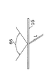
- Figure 3B illustrates how incident light is reflected from and projected through the projection surface.
- Figure 3C illustrates how incident light is reflected from and projected through the projection surface.
- Figure 4 is a block diagram illustrating how the system software is configured for programming processor(s) to implement the table system of Figure 2.
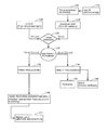
- Figure 5 is a flowchart explaining how the hybrid signal processing is performed to detect objects, such as the user's hand, in three-dimensional space.
- Figure 6A is a detailed view of the three-dimensional space, illustrating how the correlator performs structured light and projected light data fusion and illustrating.
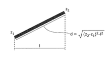
- Figure 6B is a detailed view of the three-dimensional space, illustrating how dimensions within the three-dimensional space may be calculated.
- Figure 7 is a block diagram illustrating how the processor is programmed to perform the application engine functions.
- Figure 8 depicts various user hand gestural movements that are detectable using the disclosed hand and object tracking system.
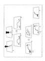
- Figure 9 (comprising Figures 9a-9h) depicts additional user hand gestural movements that are detectable using the disclosed hand and object tracking system.
- an exemplary hybrid system for tracking an object in three-dimensional space utilizes a projection surface 16 with a light source 18 disposed in spaced relation to surface 16 to define a volume of space 20 that is illuminated by the light source 18.
- the hybrid system uses two sensing systems: a projection sensing system (e.g., a shadow-projection system) and a structured light sensing system.
- a projection sensing system e.g., a shadow-projection system
- a structured light sensing system e.g., a shadow-projection system
- Each of these sensing systems may use its own light source, optimized for that system. If desired, these separate light sources can be packaged within or implemented by a common unit.
- Figure 1 illustrates generally an illumination source 17. It will be understood that this illumination source may contain or function as the light source 18, and also contain or function as a structured light source (described below as structured light source 30), depending on how the system is configured.
- a light sensor 22 is disposed beneath the projection surface 16, namely, on the opposite side from the light source 18, so that it is responsive to illumination falling on the protection surface 16 and is operative to measure illumination levels over a predefined image plane associated with the light sensor.
- light sensor 22 responds primarily to light from light source 18 falling onto and being transmitted through the projection surface to measure shadows cast on the surface by objects disposed within the volume of space 20.
- a hand 24 is placed within the volume of space and casts a shadow 26 which is then observed by and recorded by the light sensor 22 to generate a projected image (e.g., shadow) signal or data that is fed to image processing circuitry 28.
- the apparatus further includes a structured light source 30 that projects a structured light within the volume of space 20.
- the light source 18 and the structured light source 30, shown collectively as illumination source 17, can be implemented using a single illumination system where the light from light source 18 and structured light from structured light source 30 are differentiated from one another through time multiplexing or wavelength multiplexing.
- the light source alternates between a constant illumination and a structured light illumination.
- a constant light is projected at a first wavelength and a structured light is projected at a second wavelength.
- Other techniques for differentiating between the shadow casting light source 18 and the structured light source 30 are also possible.
- the structured light source 30 is read by a structured light sensor 32 that is positioned and adapted to record reflected structured light from objects occupying the volume of space 20.
- the structured light sensor produces a structured light signal or data that is supplied to a correlator 34 and then to the 3D image processing circuitry 36.
- the correlator 34 may also be coupled to the structured light source 30 to allow the structured light source as projected to be compared with the structured light as reflected from objects placed within the volume of space 20.
- Correlator 34 may be implemented using a suitably programmed microprocessor, digital signal processor, or dedicated application-specific integrated circuit
- a typical structured light pattern will comprise a geometric grid of equally spaced dots or grid lines that emanate outwardly from the point of origin. Because the structured light typically emanates from a point, the spatial resolution decreases in the direction shown by arrow 33 as objects within the volume of space 20 move away from the light source. This is also illustrated by comparing the grids 35a and 35b. As shown, the grid size increases with increasing distance, thus reducing the resolution. By comparison, the shadow 26 cast upon projection surface 16 is measured using the two-dimensional coordinates of the light sensor 22.
- the projection surface 16 lies in a plane generally optically parallel to the sensor 22 (sensor 22 may have, for example, a CCD array embedded therein, where the plane of the array is optically parallel to the surface 16).
- sensor 22 may have, for example, a CCD array embedded therein, where the plane of the array is optically parallel to the surface 16.
- the measuring resolution of light sensor 22 does not change with distance.
- mirrors or prisms may be used to place the sensor's sensing surface in an optically parallel relation to the projection surface.
- the structured light sensor 32 and optical sensor 34 are both measuring position of an object within space 20, the reference frames and geometric properties of the respective measuring systems are not the same. This difference is actually an advantage because the respective systems can be mathematically correlated so that measuring errors or resolution deficiencies within one system are actually compensated for by the other. Intuitively, one can see that when the object (hand 24) is close to surface 16, the shadow cast will be quite precise (little fringing due to diffusion) and thus the light sensor 22 is able to capture a precise two-dimensional position in its reference space notwithstanding that the resolution from structured light sensor 32 is degraded due to distance.
- the two position-measuring systems complement one another, one providing higher resolution when the other is suffering from poor resolution, and vice versa.
- correlator 38 may supply an enhanced tracking output that may be stored in memory 40 for use by other systems, as will be described.
- Each of the respective inputs to correlator 38 is processed by respective image processing circuitry 28 and 36 to generator positional information with respect to a common reference frame.
- Image processing circuitry 28 processes the raw data from light sensor 22 to define a shape corresponding to shadow 26.
- the shadow will be substantially dark in the center, but may have a less dark (fuzzy) periphery where some of the light rays bend around the edges of the object. This is compensated for by the image processing circuitry by applying a contrast increasing algorithm and by performing edge detection to generate a two-dimensional contour representing the outline of the shadow 26.
- the image processing circuitry can use this information to infer object position in the third dimension (outwardly from plane of surface 16). This may be accomplished by quantifying the degree of fringing effect. An object placed directly on surface 16 will have a sharp contour edge with no fringing, whereas an object placed near the light source will have a large fringing region.
- the image processing circuitry 28 calculates a numeric value indicative of relative distance from the surface 16. To enhance this third-dimension resolving capability, it is best to use a projection light source that can be discriminated from other ambient light sources within the room where the apparatus is located. This may be accomplished, for example, by employing a wavelength of projected light that is not prevalent in room lighting systems, or by modulating the projected light of a characteristic signal not found in ambient lighting systems.
- the image processing circuitry 28 may use the third-dimension information it has obtained to compensate for parallax error caused by differences in the angle of the incidence at different locations on the projection surface.
- incident light rays are perpendicular to the surface, whereas at the outer boundaries of the surface, incident light rays strike at a non-perpendicular angle.
- the relating shadow cast by an object within the space 20 will fall on the projection surface with some varying degree of parallax error, depending on how far out of perpendicular the incident light rays happen to be.
- the shadow cast will begin to increase in size but with a distortion that depends on angle of incidence at the object's boundary.
- the 3D image processing circuitry 36 performs the different function of determining the three-dimensional position of an object based on its contours.
- the structured light pattern has a predefined appearance when viewed by structured light sensor 32.
- certain regions within the field of view of sensor 32 will be perturbed due to the presence of the object causing certain structured light elements to be reflected from the object.
- These perturbations are treated as offsets from the standard structured light pattern.
- a structured light pattern reflecting from a series of stacked blocks is shown at 36a in Figure 1. Note how the structured light lines are offset where the edges of the blocks appear.
- the 3D image processing circuitry 36 converts the raw reflected structured light data into 3D object contour data with associated position and rotation information (x, y, z, yaw, pitch, roll). These positional and rotational data points are also transformed (if necessary) to move the data to a reference frame shared with image processing circuitry 28. In other words, the data from the respective image processing circuitry 28 and 36 are placed in the same reference frame so that the correlator 38 can correlate points in space generated by image processing circuitry 28 with the corresponding points in space generated by 3D image processing circuitry 36.
- Figure 1 defines a hybrid system where objects within the volume of space 20 are tracked using two disparate but correlated sensing systems.
- the hybrid technique may be applied in a multitude of different applications.
- An exemplary application will now be described in connection with Figure 2.
- Figure 2 depicts a 3D table system with which users view virtual three-dimensional objects and manipulate those objects by hand movements and gestural commands within the three-dimensional space above the table.
- the 3D table comprises a frame 46 into which the projection surface 16 is mounted.
- the frame includes a suitable column 48 onto which is mounted the illumination source 17 (containing both the functionality of light source 18 and structured light source 30) and the structured light sensor 32.
- the light sensor 22 is mounted beneath the projection surface 16 and may be trained on the underside of the projection surface 16 by a suitable mirror 50.
- the structured light sensor 32 and the light sensor 22 thus observe the volume of space 20 from their respective vantage points.
- 3D projector 52 is disposed beneath the projection surface 16 and projects an image onto the underside of projection surface 16 via a mirror 54.
- a second 3D projector 56 is mounted on column 48 to project images onto the upper surface of the projection surface 16.
- Both 3D projectors are preferably equipped with image correction optics so that the images projected onto the surface 16 appear without distortion, notwithstanding the fact that the projector is not necessarily aimed at the center of the surface.
- the 3D projectors are designed to work with 3D glasses 58. These glasses work by providing a different image to each of the left and right eyes. While there are a variety of different technologies for producing the 3D effect, the illustrated embodiment employs 3D glasses using a shutter technology whereby the left and right lenses are alternatively toggled on and off in synchronism with the projection of separate left and right images from the 3D projectors.
- the illustrated embodiment includes a shutter synchronizing circuit 60 that is connected to the 3D projectors 52 and wirelessly connected to the glasses 58.
- the wireless connection may be implemented using Bluetooth or other suitable wireless communication protocol.
- a speaker system 62 may also be installed on the frame to provide audible feedback as part of the 3D experience.
- the 3D glasses 58 are designed to include head tracking sensors that are monitored by a head tracking system 64.
- the glasses 58 are equipped with reflective surfaces disposed on the eyeglass frame, which create a geometric pattern that can be monitored by the head tracking system 64.
- the head tracking system emits illumination such as infrared illumination that is reflected from the reflective surfaces from the glasses and then observed by infrared photo sensors located in the head tracking system. Because the geometric arrangement of the reflective surfaces on the glasses frame is fixed, the changes in reflective infrared light patterns as the user moves his or her head can be geometrically translated into user head position or user eye position data.
- the images fed to the 3D projector are adjusted to make slight alterations to the projected information for the respective left or right eyes. Doing so ensures that a realistic 3D effect is observed regardless of the user's current head or eye position.
- the user views images projected onto the projection surface 16 using the 3D glasses.
- the 3D effect makes objects appear to be floating above the projection surface 16 within the volume of space 20.
- the user seeing a virtual 3D object within space 20, may reach out and manipulate that object with his or her hand.
- the two disparate position-sensing systems track the user's hand and extract information from the data to infer not only position but also orientation and optionally additional information such as whether the hand is open or closed, whether one or more fingers are extended, and the like.
- the two disparate position-sensing systems track the user's hand and extract information from the data to infer not only position but also orientation and optionally additional information such as whether the hand is open or closed, whether one or more fingers are extended, and the like.
- the object follows as if it were a physical object.
- the 3D tracking system can also respond to other types of gestural movements as will be described more fully below.
- the projection surface 16 is preferably designed to provide a wide field of view for incident light reflected both from above and below the surface.
- a suitable embodiment of this surface is illustrated in Figures 3A-3C.
- the actual reflective surface is preferably both reflective and translucent to allow incident light L projected from above as shown in Fig. 3B and incident light L projected from below as shown in Fig 3C to be viewed over a wide dispersion angle 66. While a variety of different materials are suitable for this purpose, the illustrated embodiment employs a vinyl fabric or film sheet as the projection surface 16. This sheet is sandwiched between a top acrylic layer 68 and a bottom acrylic layer 70. The sandwiched layers are then mounted in a suitable frame 72 which may include individual speaker elements of the speaker system 62.
- the frame may be fabricated from plywood or other suitable material to help disperse thermal heating caused by the 3D projectors.
- the bottom acrylic layer 70 is preferably fabricated from a sturdy, rigid transparent layer to ensure that the projection surface 16 remains flat.
- the top acrylic layer is preferably treated with an anti-reflective coating so that minimal reflection or glare is projected to the users.
- the resulting projection surface 16 thus serves the dual purpose of a projection surface for displaying images from the 3D projectors and also a transmissive surface that allows cast shadows to be observed by light sensor 22 and thus capture information about the user's hand position.
- the functionality of the 3D table system and also of the hybrid tracking system may be implemented by suitably programmed processors or computers.
- the 3D rendering processor 76 is responsible for rendering the 3D output projected to the user through the 3D projectors 52 and 56.
- the 3D rendering processor receiving head tracking information from the head tracking system 64, preferably including both time-stamped location and viewing angle information.
- the 3D rendering processor supplies the synchronization signal that is fed to the shutter synchronizing circuit 60.
- the 3D rendering processor is likewise responsible for supplying image information to the respective 3D projectors 52 and 56.
- the system further includes main processor 80 which has associated memory or storage 82 and is coupled to the rendering processor 76 and also to the 3D sound system 84 driving speakers 62 (e.g., mounted on frame 46, and disposed within the projection surface frame 72).
- the main processor 80 is equipped with input/output connectivity circuitry 86 to allow the main processor to communicate with personal devices 88, such as smart phones, tablet computers, personal computers and the like. Connectively, circuitry 86 is also designed to establish communication with network-based cloud services 90.
- the main processor 80 receives as an input the enhanced tracking output data (as stored in memory 40, Fig. 1) and uses this input to generate reactions to user hand movement and gestural interpretation.
- the functionality provided by the image processing circuitry 28 and 3D image processing circuitry 36 (Fig.
- FIG. 1 has been illustrated in greater detail in Figure 4 generally within the dashed region 92.
- the inputs for this processing functionality comprise the light sensor 22 and the structured light sensor 32, which are both shown in Figure 4.
- Shadow processing 94 is performed on the output data from light sensor 22, followed by object location at 96. Both of these processing functions are performed by the image processing circuitry 28 (Fig. 1).
- the shadow processing 94 operations feed the gesture detection function 98.
- the output of structured light sensor 32 is processed by the 3D image processing circuitry 36 (Fig. 1) to process the RGB (red, green, blue) data as at 100 and also to perform depth processing as at 102.
- the RGB processing supplies information to the object ID and tracking process 104 while the depth processing function provides information to the hand shape, spotting and tracking function 106.
- the hand shape, spotting and tracking function 106 also supplies input to the gesture detection function 98.
- the gesture detection function 98 triggers the gesture interpretation function 108, which supplies its output to the main processor 80.
- the gesture interpretation function 108 also utilizes finger identification and tracking information supplied by process 110, which is in turn responsive to the hand shape, spotting and tracking function 106.
- the depth and RGB processing functions 100 and 102 may also be processed to extract user identity as at 112. This information is then used by the gesture interpretation function 108.
- FIG. 5 an exemplary embodiment of the hybrid process for fusing data from the respective systems to detect and track objects in three-dimensional space will now be described.
- IR infrared
- Data obtained from the structured light system are depicted at 120.
- the data may be considered as a point cloud of three-dimensional points in space 20.
- These data are captured and stored with respect to the intrinsic parameters of the structured light sensor and are converted, if required, to a three-dimensional image space referred to in Figure 5 as I(x,y,z).
- raw infrared (IR) camera image data from light sensor 22 (Fig. 1) are captured and stored as at 122.
- the raw image data are preprocessed and de-noised at 124.
- the preprocessing steps are particularly useful if the light source used for shadow projection is, itself, a structured light source (i.e., the light source 18 of Figure 1 is eliminated and structured light source 30 serves double duty).
- a blurring algorithm is used, followed by connected component analysis and selection (to select and retain only objects greater than a predetermined size T).
- a contour of the selected connected components may be further refined by a sequence of: morphological operators>>blurring>>thresholding to obtain a very smooth contour.
- the smooth contour is referenced in Figure 5 as a shadow map 126. It represents objects' shadows, projected onto the projection surface 16 (Fig. 1) as viewed by light sensor 22. In the embodiment shown in Fig. 2, the light sensor is beneath the surface, thus surface 16 in such embodiment needs to be transparent at the light wavelength being used (e.g., infrared wavelength).
- the contour represents the location of the shadow in two-dimensional reference frame, referenced in Figure 5 as I(x,y).
- the correlator 34 performs a hand detection algorithm 128 where data from each source is processed.
- the hand detection algorithm treats each contour as a blob, which the detection algorithm compares with a set of known shapes, including a human hand and other shapes that may be used with the system.
- the hand detection algorithm may comprise, for example, an artificial intelligence (AI) system employing a Haar transform-based feature classifier trained to recognize hand and non-hand shapes.
- AI artificial intelligence
- These training data are stored in a database of shadow maps that are used by the correlator in comparing an input blob (contour) with each entry in the database to determine which shape has matches with the highest likelihood score.
- the AI expert system applies a set of rules to the potential hand cloud, using a priori knowledge about the hand, such as the average length of a human arm, the average diameter of the palm, the fact that a hand is always attached to an arm that crosses the borders of the camera frame (i.e., hands do not float by themselves in midair).
- a priori knowledge about the hand such as the average length of a human arm, the average diameter of the palm, the fact that a hand is always attached to an arm that crosses the borders of the camera frame (i.e., hands do not float by themselves in midair).
- the expert system alone may not make a final decision regarding hand and object identification when multiple objects are observed in the space 20.
- Cloud data alone may not be precise enough to be used as the sole input for feature-based classification algorithms. For this reason, a classifier may be applied to the shadow map.
- the precision of the hybrid system comes from the combination of the two disparate sensing sources.
- the shadow map for example, cannot handle occlusion (where one object in three-dimensional space blocks light from reaching an object below).
- the cloud data are able to obtain additional data about both objects when occlusion occurs.
- the resolution of the cloud data may be degraded as the object moves farther from the light source, whereas the shadow data actually become even more precise as the object moves farther from the light source and hence closer to the projection surface.
- the router/multiplexer steers the cloud data I(x,y,z) and shadow map data I(x,y) to the proper processing block, hand processing block 132 or object processing block 134.
- This routing step may be implemented by storing the respective data I(x,y,z) and I(x,y) in memory and then causing the correlator's processor to operate on that data via either the hand processing algorithm or the object processing algorithm.
- the hand processing algorithm extracts features such as the center of the palm and the position and direction of the fingers.
- the algorithm relies on an analysis of the three-dimensional contour obtained by combining the shadow map data and the point cloud data as follows:
- the shadow is treated as a slice of the full hand cloud.
- the algorithm re-projects the shadow map into the cloud as shown in Figure 6A.
- the shadow map contains precise contour information, while the cloud contains valuable 3D information.
- the algorithm selects a contour (a 3D strip) around the slice, including all the points in the cloud that are closest to the slice.
- the inclusion/exclusion decision is performed according to a distance threshold from the slice contour.
- the extracted 3D contour combines the precision of the shadow map contour together with the 3D information of the cloud, particularly the surface normal information extracted from the 3D points.
- the algorithm differentiates tips of the fingers from valleys between fingers.
- the correlation processor is programmed to identify fingers of a human hand by computing a plurality of geometric normal vectors along the contour of the point cloud and classifying those normal vectors to differentiate between finger tips and valleys between fingers, based on whether a group of adjacent normal vectors diverge (indicative of a tip), or converge (indicative of a valley).
- the center of the hand is computed as the 3D mean of points belonging to the 3D contour, while the variance gives a rough estimation of the hand being open or closed.
- the object processing algorithm is performed over those objects that are not classified as hands. Different processing steps are performed, depending on the objective desired by the user. If the user is interested in scanning an object to obtain the full 3D model, then the slice method scanning algorithm 136 proceeds as follows:
- the algorithm only considers a subportion of the cloud around the re-projected shadow of the object, whose precision is refined by the cloud itself. We call this sub portion strip.
- the algorithm captures multiple different ones of these strips from different vantage points, i.e., from different views of the object. Using an iterative closest point algorithm, these multiple strips are matched with high precision until a full dense cloud of the object is captured. The cloud can then be post-processed to obtain a triangulated mesh.
- the measurement algorithm 138 proceeds as follows: In determining precise measurements, it must be recognized that a shadow map is only capable of giving the measurements for the projection of the objects on the surface.
- the cloud is not precise enough to give good measurements, but it can be trusted to yield z-axis information at the extremities of the object, by averaging neighborhood data.
- the two different types of data so obtained are then combined using a trigonometric relationship as illustrated in Figure 6B. This is performed by identifying at least two points on the contour of the point cloud that correspond to at least two points associated with the projected image signal. The distances between points on the point cloud and corresponding points associated with the projected image signal are then determined. Finally, using the trigonometric relationship shown in Fig. 6B, the dimension of said object based on the locations of the identified points and on the determined distances is calculated.
- hand processing 132
- additional feature extraction and hand feature understanding may be performed as depicted at 140 and 142 in Fig. 5.
- Figure 7 illustrates how the main processor 80 may be configured to perform the system functions described herein.
- the structured light system comprising structured light source 30 and structured light sensor 32 are depicted diagrammatically; likewise, the projection subsystem comprising light source 18 and light sensor 22 have been depicted diagrammatically.
- the main processor 80 supplies 3D render data to the 3D projector 52, which projects its image upon surface 16.
- the main processor 80 is programmed to maintain a data structure that stores the application state, illustrated diagrammatically as data store 150.
- the 3D render data is dynamically updated in synchronism with the wearer's 3D glasses 58 based on the application state and other calculated parameters.
- the data from the structured light subsystem and from the projection subsystem are processed by processor 80 at block 152 to determine the user interaction mode.
- the structured light subsystem provides data from which the user's "gesture type" is calculated. These data include data indicative of the detected object's identity (e.g., a human hand, left hand or right hand; an object, an object held by a human hand, etc.), data indicative of the object's 3D position and data indicative of any detected gestural movement.
- the data from the projection subsystem include data indicative of detected object location and view angle.
- the processor 80 at block 152 uses these input data to determine what user interface (UI) mode to use in adjusting content and/or scene delivered to the 3D projector and also to adjust the application state maintained by the processor in its memory at data store 150. This functionality is represented by block 154.
- the UI mode information is also used by processor 80 at block 156 to generate and provide user interface usage guidance to the user, which information is also ultimately fed to the 3D projector 52 after being dynamically updated at block 158 as a projection matrix that takes into account the user's head position as measured by the glasses 58 and head tracking system 64 (Fig. 2).
- Figures 8a-8d depict exemplary two-dimensional binary swipe gestures that might be used, for example, to move a list so as to focus on the next item or a previous item.
- Figure 8a depicts a sideways gesture while Figure 8b depicts a vertical gesture.
- Figures 8c and 8d depict two-dimensional continuous swipe gestures that evoke physics-based list interaction where the swipe gesture smoothly scrolls across one or many items in a list, with momentum and decay as well as bouncing and snapping, to simulate the physical movement of physical objects.
- Figure 8e depicts a one-hand, one-to-one direct manipulation where a circular hand motion, for example, produces a corresponding circular motion in the displayed object.
- Figures 8f, 8g and 8h depict two-hand two-dimensional zoom, pan and rotate operations, respectively. In each of these operations, there is a one-to-one direct manipulation of the displayed object.
- Figures 8i and 8j depict a two-dimensional joystick pinch operation. As shown in Figure 8i, a pinch of the fingers and a movement of the hand to a desired direction produces a corresponding screen movement as shown in 8j.
- Figures 9a-9h show further exemplary gestures.
- Figures 9a and 9b illustrate a three-dimensional up/down gesture which might be performed with one or two hands.
- the up gesture illustrated in Figure 9a may be used, for example, to enter a virtual building or to pull up a menu or object in virtual space.
- the down gesture illustrated in Figure 9b may be used, for example, to close a menu or push down an object in virtual space.
- Figures 9a and 9b depict a three-dimensional one-to-one direct manipulation of a virtual object in three-dimensional space in a one-to-one mode.
- the user is grasping and moving a perceived virtual image, causing the virtual image (a cube) to move in three-dimensional space as shown in Figure 9d.
- Figures 9e-9f illustrate an exemplary two-dimensional swipe maneuver to perform a gesture-based list interaction.
- the user moves his or her hand in a swiping motion in reference to a stack of cards displayed on the projection surface. This motion causes the cards to fan out into a spatial array as shown in Figure 9f. Doing this allows the user to then pick one of the cards for further interaction.
- Figures 9g and 9h show the reverse action whereby a swiping gesture performed at Figure 9g closes the array of cards from Figure 9f back to the stacked arrangement as shown in Figure 9h.
- the disclosure is applicable to a hybrid tracking system that uses both structured light and shadow-projection light to capture position and orientation information.
Landscapes
- Engineering & Computer Science (AREA)
- Physics & Mathematics (AREA)
- General Physics & Mathematics (AREA)
- Theoretical Computer Science (AREA)
- General Engineering & Computer Science (AREA)
- Computer Vision & Pattern Recognition (AREA)
- Human Computer Interaction (AREA)
- Optics & Photonics (AREA)
- Electromagnetism (AREA)
- Radar, Positioning & Navigation (AREA)
- Remote Sensing (AREA)
- Length Measuring Devices By Optical Means (AREA)
Priority Applications (1)
| Application Number | Priority Date | Filing Date | Title |
|---|---|---|---|
| US14/594,554 US9720511B2 (en) | 2012-07-13 | 2015-01-12 | Hand and object tracking in three-dimensional space |
Applications Claiming Priority (2)
| Application Number | Priority Date | Filing Date | Title |
|---|---|---|---|
| US201261671134P | 2012-07-13 | 2012-07-13 | |
| US61/671,134 | 2012-07-13 |
Related Child Applications (1)
| Application Number | Title | Priority Date | Filing Date |
|---|---|---|---|
| US14/594,554 Continuation US9720511B2 (en) | 2012-07-13 | 2015-01-12 | Hand and object tracking in three-dimensional space |
Publications (1)
| Publication Number | Publication Date |
|---|---|
| WO2014010251A1 true WO2014010251A1 (fr) | 2014-01-16 |
Family
ID=48906471
Family Applications (1)
| Application Number | Title | Priority Date | Filing Date |
|---|---|---|---|
| PCT/JP2013/004307 Ceased WO2014010251A1 (fr) | 2012-07-13 | 2013-07-12 | Suivi de main et d'objet dans un espace tridimensionnel |
Country Status (2)
| Country | Link |
|---|---|
| US (1) | US9720511B2 (fr) |
| WO (1) | WO2014010251A1 (fr) |
Cited By (4)
| Publication number | Priority date | Publication date | Assignee | Title |
|---|---|---|---|---|
| WO2018031249A1 (fr) * | 2016-08-08 | 2018-02-15 | Microsoft Technology Licensing, Llc | Capteur d'imagerie hybride permettant la capture d'objets à lumière structurée |
| US10268277B2 (en) | 2014-09-30 | 2019-04-23 | Hewlett-Packard Development Company, L.P. | Gesture based manipulation of three-dimensional images |
| US20220277460A1 (en) * | 2019-08-30 | 2022-09-01 | Ntt Docomo, Inc. | Projection controlling apparatus and projection system |
| US11635767B2 (en) * | 2019-02-13 | 2023-04-25 | Semyon Nisenzon | System and method of using multi-resolution camera clusters input data for controlling autonomous vehicles |
Families Citing this family (18)
| Publication number | Priority date | Publication date | Assignee | Title |
|---|---|---|---|---|
| FR2976681B1 (fr) * | 2011-06-17 | 2013-07-12 | Inst Nat Rech Inf Automat | Systeme de colocalisation d'un ecran tactile et d'un objet virtuel et dispostif pour la manipulation d'objets virtuels mettant en oeuvre un tel systeme |
| US9529428B1 (en) * | 2014-03-28 | 2016-12-27 | Amazon Technologies, Inc. | Using head movement to adjust focus on content of a display |
| US10169909B2 (en) * | 2014-08-07 | 2019-01-01 | Pixar | Generating a volumetric projection for an object |
| US9858703B2 (en) * | 2014-12-18 | 2018-01-02 | Facebook, Inc. | System, device and method for providing user interface for a virtual reality environment |
| US20170074641A1 (en) * | 2015-09-14 | 2017-03-16 | Michael Dean Tschirhart | Translating natural motion to a command |
| US10755132B2 (en) * | 2016-01-15 | 2020-08-25 | Wuhan Wuda Zoyon Science And Technology Co., Ltd | Methods for extracting surface deformation feature of object based on linear scanning three-dimensional point cloud |
| US10067636B2 (en) * | 2016-02-09 | 2018-09-04 | Unity IPR ApS | Systems and methods for a virtual reality editor |
| JP6713622B2 (ja) * | 2016-03-04 | 2020-06-24 | 株式会社アプライド・ビジョン・システムズ | 3次元計測装置、3次元計測システム、3次元計測方法及びプログラム |
| CN109563816B (zh) * | 2016-07-08 | 2022-03-22 | 西门子歌美飒可再生能源公司 | 阴影检测 |
| US10591277B2 (en) | 2016-07-28 | 2020-03-17 | Liberty Reach Inc. | Method and system for measuring outermost dimension of a vehicle positioned at an inspection station |
| US10049443B2 (en) | 2016-08-29 | 2018-08-14 | Liberty Reach Inc. | Method and system for determining the presence or absence of a part of an assembly within a work cell |
| US10281994B2 (en) * | 2017-06-16 | 2019-05-07 | Anousheh Sayah | Smart wand device |
| FR3069941B1 (fr) * | 2017-08-03 | 2020-06-26 | Safran | Procede de controle non destructif d'une piece aeronautique et systeme associe |
| US11029713B2 (en) | 2017-11-27 | 2021-06-08 | Liberty Reach Inc. | Method and system for expanding the range of working environments in which a 3-D or depth sensor can operate without damaging or degrading the measurement performance of the sensor |
| KR102004991B1 (ko) * | 2017-12-22 | 2019-10-01 | 삼성전자주식회사 | 이미지 처리 방법 및 그에 따른 디스플레이 장치 |
| US10623725B2 (en) * | 2018-01-03 | 2020-04-14 | Votanic Ltd. | 3D glasses incorporating real-time tracking |
| US10452947B1 (en) | 2018-06-08 | 2019-10-22 | Microsoft Technology Licensing, Llc | Object recognition using depth and multi-spectral camera |
| US11245875B2 (en) * | 2019-01-15 | 2022-02-08 | Microsoft Technology Licensing, Llc | Monitoring activity with depth and multi-spectral camera |
Citations (7)
| Publication number | Priority date | Publication date | Assignee | Title |
|---|---|---|---|---|
| JP2002213947A (ja) | 2001-01-17 | 2002-07-31 | Fuji Xerox Co Ltd | ターゲット位置を測定するシステム及びその方法 |
| JP2003269915A (ja) | 2002-03-13 | 2003-09-25 | Omron Corp | 三次元監視装置 |
| US20040041996A1 (en) * | 2002-08-28 | 2004-03-04 | Fuji Xerox Co., Ltd. | Range finder and method |
| US20110096072A1 (en) * | 2009-10-27 | 2011-04-28 | Samsung Electronics Co., Ltd. | Three-dimensional space interface apparatus and method |
| WO2011066916A1 (fr) * | 2009-12-01 | 2011-06-09 | ETH Zürich, ETH Transfer | Procédé et dispositif informatique pour générer un corps en 3d |
| US20110205341A1 (en) * | 2010-02-23 | 2011-08-25 | Microsoft Corporation | Projectors and depth cameras for deviceless augmented reality and interaction. |
| WO2012054063A1 (fr) * | 2010-10-22 | 2012-04-26 | Hewlett-Packard Development Company L.P. | Système d'affichage à réalité augmentée et procédé d'affichage |
Family Cites Families (15)
| Publication number | Priority date | Publication date | Assignee | Title |
|---|---|---|---|---|
| US8406479B2 (en) * | 2006-07-14 | 2013-03-26 | Panasonic Corporation | Visual axis direction detection device and visual line direction detection method |
| US9489102B2 (en) | 2010-10-22 | 2016-11-08 | Hewlett-Packard Development Company, L.P. | System and method of modifying lighting in a display system |
| US20120098761A1 (en) | 2010-10-22 | 2012-04-26 | April Slayden Mitchell | Display system and method of display for supporting multiple display modes |
| US20120102438A1 (en) | 2010-10-22 | 2012-04-26 | Robinson Ian N | Display system and method of displaying based on device interactions |
| US8854802B2 (en) | 2010-10-22 | 2014-10-07 | Hewlett-Packard Development Company, L.P. | Display with rotatable display screen |
| US20120102439A1 (en) | 2010-10-22 | 2012-04-26 | April Slayden Mitchell | System and method of modifying the display content based on sensor input |
| US8791901B2 (en) * | 2011-04-12 | 2014-07-29 | Sony Computer Entertainment, Inc. | Object tracking with projected reference patterns |
| US9880640B2 (en) * | 2011-10-06 | 2018-01-30 | Amazon Technologies, Inc. | Multi-dimensional interface |
| US9424467B2 (en) * | 2013-03-14 | 2016-08-23 | Disney Enterprises, Inc. | Gaze tracking and recognition with image location |
| US9507472B2 (en) * | 2013-07-10 | 2016-11-29 | Synaptics Incorporated | Hybrid capacitive baseline management |
| US20150015528A1 (en) * | 2013-07-10 | 2015-01-15 | Synaptics Incorporated | Hybrid capacitive image determination and use |
| US10466858B2 (en) * | 2013-12-01 | 2019-11-05 | Upskill, Inc. | Systems and methods for interacting with a virtual menu |
| US9507470B2 (en) * | 2013-12-16 | 2016-11-29 | Nvidia Corporation | Method and system for reduced power touch input detection on an electronic device using reduced scanning |
| US9529428B1 (en) * | 2014-03-28 | 2016-12-27 | Amazon Technologies, Inc. | Using head movement to adjust focus on content of a display |
| US9454278B2 (en) * | 2014-04-25 | 2016-09-27 | Synaptics Incorporated | Weighting for display noise removal in capacitive sensors |
-
2013
- 2013-07-12 WO PCT/JP2013/004307 patent/WO2014010251A1/fr not_active Ceased
-
2015
- 2015-01-12 US US14/594,554 patent/US9720511B2/en not_active Expired - Fee Related
Patent Citations (7)
| Publication number | Priority date | Publication date | Assignee | Title |
|---|---|---|---|---|
| JP2002213947A (ja) | 2001-01-17 | 2002-07-31 | Fuji Xerox Co Ltd | ターゲット位置を測定するシステム及びその方法 |
| JP2003269915A (ja) | 2002-03-13 | 2003-09-25 | Omron Corp | 三次元監視装置 |
| US20040041996A1 (en) * | 2002-08-28 | 2004-03-04 | Fuji Xerox Co., Ltd. | Range finder and method |
| US20110096072A1 (en) * | 2009-10-27 | 2011-04-28 | Samsung Electronics Co., Ltd. | Three-dimensional space interface apparatus and method |
| WO2011066916A1 (fr) * | 2009-12-01 | 2011-06-09 | ETH Zürich, ETH Transfer | Procédé et dispositif informatique pour générer un corps en 3d |
| US20110205341A1 (en) * | 2010-02-23 | 2011-08-25 | Microsoft Corporation | Projectors and depth cameras for deviceless augmented reality and interaction. |
| WO2012054063A1 (fr) * | 2010-10-22 | 2012-04-26 | Hewlett-Packard Development Company L.P. | Système d'affichage à réalité augmentée et procédé d'affichage |
Non-Patent Citations (3)
| Title |
|---|
| ABRAHAM PRIETO ET AL: "An Adaptive Visual Gesture Based Interface for Human Machine Interaction in Intelligent Workspaces", VIRTUAL ENVIRONMENTS, HUMAN-COMPUTER INTERFACES AND MEASUREMENT SYSTEM S, PROCEEDINGS OF 2006 IEEE INTERNATIONAL CONFERENCE ON, IEEE, PI, 1 July 2006 (2006-07-01), pages 43 - 48, XP031019086, ISBN: 978-1-4244-0242-7 * |
| MICHAEL VAN DEN BERGH ET AL: "Combining RGB and ToF cameras for real-time 3D hand gesture interaction", APPLICATIONS OF COMPUTER VISION (WACV), 2011 IEEE WORKSHOP ON, IEEE, 5 January 2011 (2011-01-05), pages 66 - 72, XP031913555, ISBN: 978-1-4244-9496-5, DOI: 10.1109/WACV.2011.5711485 * |
| SEGEN J ET AL: "Shadow gestures: 3D hand pose estimation using a single camera", PROCEEDINGS OF THE 1999 IEEE COMPUTER SOCIETY CONFERENCE ON COMPUTER VISION AND PATTERN RECOGNITION, JUNE 23-25, 1999; FORT COLLINS, COLORADO, IEEE, THE INSTITUTE OF ELECTRICAL AND ELECTRONICS ENGINEERS, INC, US, vol. 1, 23 June 1999 (1999-06-23), pages 479 - 485, XP010347622, ISBN: 978-0-7695-0149-9 * |
Cited By (6)
| Publication number | Priority date | Publication date | Assignee | Title |
|---|---|---|---|---|
| US10268277B2 (en) | 2014-09-30 | 2019-04-23 | Hewlett-Packard Development Company, L.P. | Gesture based manipulation of three-dimensional images |
| WO2018031249A1 (fr) * | 2016-08-08 | 2018-02-15 | Microsoft Technology Licensing, Llc | Capteur d'imagerie hybride permettant la capture d'objets à lumière structurée |
| US10574909B2 (en) | 2016-08-08 | 2020-02-25 | Microsoft Technology Licensing, Llc | Hybrid imaging sensor for structured light object capture |
| US11635767B2 (en) * | 2019-02-13 | 2023-04-25 | Semyon Nisenzon | System and method of using multi-resolution camera clusters input data for controlling autonomous vehicles |
| US20220277460A1 (en) * | 2019-08-30 | 2022-09-01 | Ntt Docomo, Inc. | Projection controlling apparatus and projection system |
| US12243239B2 (en) * | 2019-08-30 | 2025-03-04 | Ntt Docomo, Inc. | Projection controlling apparatus and projection system |
Also Published As
| Publication number | Publication date |
|---|---|
| US9720511B2 (en) | 2017-08-01 |
| US20150124086A1 (en) | 2015-05-07 |
Similar Documents
| Publication | Publication Date | Title |
|---|---|---|
| US9720511B2 (en) | Hand and object tracking in three-dimensional space | |
| US10620712B2 (en) | Interactive input system and method | |
| US20250383719A1 (en) | Velocity field interaction for free space gesture interface and control | |
| JP5950130B2 (ja) | カメラ式マルチタッチ相互作用装置、システム及び方法 | |
| KR102335132B1 (ko) | 하나의 단일 감지 시스템을 이용하는 멀티 모드 제스처 기반의 상호작용 시스템 및 방법 | |
| US10007350B1 (en) | Integrated gestural interaction and multi-user collaboration in immersive virtual reality environments | |
| US8941620B2 (en) | System and method for a virtual multi-touch mouse and stylus apparatus | |
| US6775014B2 (en) | System and method for determining the location of a target in a room or small area | |
| US20140354602A1 (en) | Interactive input system and method | |
| US20130343601A1 (en) | Gesture based human interfaces | |
| CN104423578B (zh) | 交互式输入系统和方法 | |
| US20150131852A1 (en) | Object position determination | |
| CN110363061B (zh) | 计算机可读介质、训练对象检测算法的方法及显示装置 | |
| CN103299259A (zh) | 检测装置、输入装置、投影机以及电子设备 | |
| KR20210101027A (ko) | 전자 장치 및 그 동작 방법 | |
| KR101961266B1 (ko) | 시선 추적 장치 및 이의 시선 추적 방법 | |
| KR101385263B1 (ko) | 가상 키보드를 위한 시스템 및 방법 | |
| JP6233941B1 (ja) | 非接触式の三次元タッチパネル、非接触式の三次元タッチパネルシステム、非接触式の三次元タッチパネルの制御方法、プログラム及び記録媒体 | |
| Annabel et al. | Design and Development of Multimodal Virtual Mouse | |
| KR20150137908A (ko) | 홀로그래피 터치 방법 및 프로젝터 터치 방법 | |
| MUSTAFA | FINGER GESTURE RECOGNITION IN DYNAMIC ENVIORMENT UNDER VARYING ILLUMINATION UPON ARBITRARY BACKGROUND | |
| Avellino | A framework for inexpensive and unobtrusive tracking of everyday objects and single-touch detection | |
| NO20130840A1 (no) | Kamerabasert, multitouch interaksjons- og belysningssystem samt fremgangsmåte | |
| KR20160014091A (ko) | 홀로그래피 터치 기술 및 프로젝터 터치 기술 | |
| KR20150136759A (ko) | 홀로그래피 터치 기술 및 프로젝터 터치 기술 |
Legal Events
| Date | Code | Title | Description |
|---|---|---|---|
| 121 | Ep: the epo has been informed by wipo that ep was designated in this application |
Ref document number: 13742758 Country of ref document: EP Kind code of ref document: A1 |
|
| NENP | Non-entry into the national phase |
Ref country code: DE |
|
| 122 | Ep: pct application non-entry in european phase |
Ref document number: 13742758 Country of ref document: EP Kind code of ref document: A1 |