WO2014010264A1 - Chariot à plateforme de déplacement d'objets lourds - Google Patents
Chariot à plateforme de déplacement d'objets lourds Download PDFInfo
- Publication number
- WO2014010264A1 WO2014010264A1 PCT/JP2013/054678 JP2013054678W WO2014010264A1 WO 2014010264 A1 WO2014010264 A1 WO 2014010264A1 JP 2013054678 W JP2013054678 W JP 2013054678W WO 2014010264 A1 WO2014010264 A1 WO 2014010264A1
- Authority
- WO
- WIPO (PCT)
- Prior art keywords
- heavy
- load
- carriage
- roller
- shaft
- Prior art date
- Legal status (The legal status is an assumption and is not a legal conclusion. Google has not performed a legal analysis and makes no representation as to the accuracy of the status listed.)
- Ceased
Links
Images


Classifications
-
- B—PERFORMING OPERATIONS; TRANSPORTING
- B60—VEHICLES IN GENERAL
- B60B—VEHICLE WHEELS; CASTORS; AXLES FOR WHEELS OR CASTORS; INCREASING WHEEL ADHESION
- B60B33/00—Castors in general; Anti-clogging castors
- B60B33/0036—Castors in general; Anti-clogging castors characterised by type of wheels
- B60B33/0044—Roller type wheels, i.e. extra wide wheels
-
- B—PERFORMING OPERATIONS; TRANSPORTING
- B62—LAND VEHICLES FOR TRAVELLING OTHERWISE THAN ON RAILS
- B62B—HAND-PROPELLED VEHICLES, e.g. HAND CARTS OR PERAMBULATORS; SLEDGES
- B62B5/00—Accessories or details specially adapted for hand carts
- B62B5/0083—Wheeled supports connected to the transported object
- B62B5/0086—Wheeled supports connected to the transported object arranged independently on either side of the transported load
-
- B—PERFORMING OPERATIONS; TRANSPORTING
- B62—LAND VEHICLES FOR TRAVELLING OTHERWISE THAN ON RAILS
- B62B—HAND-PROPELLED VEHICLES, e.g. HAND CARTS OR PERAMBULATORS; SLEDGES
- B62B2203/00—Grasping, holding, supporting the objects
- B62B2203/02—Grasping, holding, supporting the objects suspended
- B62B2203/04—Grasping, holding, supporting the objects suspended pivotally, e.g. for keeping it horizontally
-
- B—PERFORMING OPERATIONS; TRANSPORTING
- B62—LAND VEHICLES FOR TRAVELLING OTHERWISE THAN ON RAILS
- B62B—HAND-PROPELLED VEHICLES, e.g. HAND CARTS OR PERAMBULATORS; SLEDGES
- B62B3/00—Hand carts having more than one axis carrying transport wheels; Steering devices therefor; Equipment therefor
- B62B3/008—Hand carts having more than one axis carrying transport wheels; Steering devices therefor; Equipment therefor having more than two axes
Definitions
- the present invention relates to a heavy goods moving carriage used for safely moving heavy goods such as furniture, refrigerators, flower pots, etc. used in general households and offices.
- FIG. 11 and FIG. 12 show a conventional mobile carriage.
- This conventional example is of the same type as that described in Patent Document 1 and that described in Patent Document 2, for example.
- a turntable 3 is provided on the main body 2 so as to be pivoted horizontally or horizontally and vertically extendable, and includes a knob 21 protruding forward from the front frame, and a plurality of pivots supported on the lower end.
- the load received from the heavy object It could move as a unit.
- the heavy object 10 is inserted into the lower four corners of the heavy object 10 such as furniture and supported by the load received from the heavy object 10 while supporting the heavy object 10.
- the unloading and the heavy goods moving carriages 1a, 1b, 1c, and 1d inserted into the four corners of the heavy article 10 may be supported by only three of the three corners or rarely two, That moving cart will be left behind.
- This left-over state that is, a state in which a heavy object floats is shown in FIG. Further, as shown in FIG.
- the load from the heavy object 10 applied to the moving carriage that has approached the slope of the floor is greatly deviated from front to back or from side to side, and the load is concentrated on a part of the rollers.
- the direction of the moving carriage is changed without permission, and some moving carriages are different in the traveling direction with respect to the heavy load 10 and the traveling is stopped.
- one of the conventional mobile trolleys has a structure in which a turntable 3 that is supported on a main body 2 so as to be horizontally rotatable and vertically extendable is provided.
- the turntable 3 can be expanded and contracted smoothly even on a floor having a difference in inclination, the extension and contraction of the turntable 3 can only move in the vertical direction.
- the load point W is added to the outer periphery of the turntable 3, and the turntable 3 that can move only in the vertical direction does not extend from the cart body 2 and can receive a load near the center of the turntable 3. Can not.
- the expansion / contraction force of the turntable 3 is constantly exerting a force to extend the whole turntable upward
- the no-load point N where the load of the turntable 3 is not applied is operated to extend from the cart body 2. Therefore, the turntable 3 operates to extend obliquely upward with respect to the carriage body 2. This causes distortion in the fitting between the turntable 3 and the recess 22 or the central boss hole 26 of the carriage body 2, and the turntable 3 generates a large friction between the carriage body 2. Smooth expansion and contraction could not be expected.
- this conventional movable carriage is arranged such that the position of the roller 5 pivotally supported on the lower part of the carriage body is outside the outer peripheral portion of the turntable 3, and the load applied to the turntable 3.
- the moving carriage is not toppled even if the position of the carriage is biased.
- the corresponding movable carriage approaches the floor distortion and the inclined portion E.
- the load point W from the heavy object 10 moves to the outer periphery of the turntable 3, and the load from the heavy object 10 is concentrated only on the roller 5 near the load point W. It becomes remarkable to join.
- a large unbalance is generated in the load applied to the front, rear, left, and right rollers 5. Therefore, a large difference occurs in the friction and resistance generated between the floor and the roller shaft between a roller that receives little load and a roller that handles the load.
- the floor F that moves furniture, etc. has distortion and height difference even with tiles, concrete floors, tiles, flooring, etc., and some mobile trolleys frequently change their stopping state and direction of travel and move Since the movement of the carriage suddenly became difficult and there was a risk of furniture falling off the moving carriage and injuring the operator and scratching the floor, the floor that could be used was limited to a flat area.
- the present invention is a floor that is widely spread in general households such as folding, flooring, tiles, stone sticking, etc., in a wide range of flooring materials that have distortion, curvature, etc., and smoothly and stably.
- An object of the present invention is to provide a heavy-duty moving carriage that can be moved safely.
- the heavy goods moving cart 1 of the present invention which has been made to solve the above-mentioned problems, is mounted on a cart body 2, a plurality of rollers 5 pivotally supported by a plurality of shafts at the bottom of the cart body 2, and an upper portion of the cart body 2.
- the load receiving bed 3 is configured to abut on the bottom surface of the heavy object to support the heavy object, and the flat part 4 can be stretched and adjusted while the inclination angle is freely movable.
- the elastic member is formed in a tapered shape outside the outer periphery of the flat portion.
- the load receiving platform 3 has a flat portion 4 in contact with the bottom surface of the heavy article 10 at the center, and forms a tapered portion in the elastic member between the outer peripheral end 3b of the flat portion and the outer peripheral end 3a of the load receiving table, and the taper of the elastic member.
- the portion is formed such that the elastic force gradually decreases from the central portion toward the outer peripheral portion, and the load receiving platform outer peripheral end 3a is in contact with the receiving portion 22 of the cart body.
- the flat surface portion 4 of the load receiving platform 3 can move freely with an inclination angle with respect to the cart body 2 and always abuts against the bottom surface of the heavy load 10 to hold the load from the heavy load 10.
- the load receiving platform 3 that receives the load from the heavy object 10 on the flat surface portion 4 starts to deform from the outer peripheral portion due to the increase of the load, and the deformation progresses to the central portion.
- the load receiving platform 3 is placed on the top of the cart body 2 so as to be in close contact with the cart body 2 when a load of a certain level or more is applied while the flat surface portions 4 of the three are always in contact with each other.
- the intermediate shaft 6b is disposed below the center portion of the flat surface portion 4, and the load from the heavy object 10 is supported by being distributed and supported by the front and rear shaft rollers 5 around the intermediate roller 5.
- the object moving carriage 1 can support a heavy object stably while always trying to receive a load at the flat surface portion 4 of the load receiving table 3 without contacting the bottom surface and the floor surface of the heavy object 10 with each other.
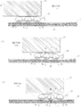
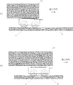
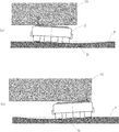
- the heavy goods moving cart 1 of the present invention encounters a groove G between the plates and the plate when the floor F moving the heavy objects 10 is flooring, or a joint groove G when tiles or stones are attached, Even if one of the front and rear intermediate rollers 5 may fall into the groove G, the roller 5 pivotally supported by the front shaft 6a hits the groove G and falls into the groove G as shown in FIG.
- the heavy-duty moving carriage 1 tends to lean forward, but at that time, the load point W applied to the load receiving platform 3 moves slightly from the center of the loading platform to the rear, and the load from the heavy load is
- the roller 5 supported by the intermediate shaft 6b and the rear shaft 6c and supported by the front shaft 6a does not fall into the groove G.
- the load applied to the load receiving platform 3 is supported by the front shaft 6a and the rear shaft 6c. Held by the roller 5 and does not fall into the groove G. Further, when the roller 5 supported by the rear shaft 6c is on the groove G as shown in FIG. 7C, the load point W applied to the load receiving platform 3 is slightly forward from the center of the platform. The load from the heavy object is held by the roller 5 supported by the intermediate shaft 6b and the front shaft 6a, and the roller 5 supported by the rear shaft 6c does not fall into the groove G. The heavy goods moving cart 1 can move smoothly.
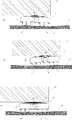
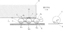
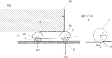
- the heavy load moving carriage 1 of the present invention intermediates the load W from the heavy load 10. Since the roller 5 supported by the shaft 6b holds almost half of the load Wb, the load Wa applied to the front shaft roller 5 facing the step H is smaller, and the heavy goods moving carriage 1 is overcome the climbing step H. Therefore, the resistance P received to move forward is small. Further, the resin cart body 2 is elastic, and the resistance received by the front shaft roller 5 is absorbed even when the cart body 2 is slightly bent and bowed around the intermediate shaft 6b.
- the heavy-duty moving carriage 1 of the present invention may leave the heavy-duty moving carriage 1 out of the heavy load 10 even if it encounters a failure such as a seam or distortion due to a floor surface that travels and moves, a slant or a gentle depression.
- a failure such as a seam or distortion due to a floor surface that travels and moves, a slant or a gentle depression.
- the heavy-duty moving carriage 1 when the heavy-duty moving carriage 1 according to the present invention is inserted into the bottom four corners of the heavy article 10 such as furniture and moved while supporting the heavy article 10, the distortion of the floor surface traveling and moving is possessed. Even when encountering obstacles such as incline and gentle dents, the heavy-duty moving carriage 1 can always travel stably without coming into contact with the bottom surface and the floor surface of the heavy object 10, so that it can be used in ordinary homes and offices. Corresponding to most of the flooring used, the heavy object 10 such as furniture can be safely, smoothly and easily performed. Further, since the load receiving platform 3 has a tapered shape toward the center of the upper surface of the cart body 1, there is an effect that it can be smoothly inserted without resistance when it is inserted into the bottom surface of the heavy object 10.
- the roller 5 is pivotally supported by the three shafts 6a, 6b, and 6c, so that the roller 5 falls into a seam groove on the floor surface that travels and the traveling of the heavy-duty moving carriage 1 stops. There is nothing. Further, even if there is an upward slope or a slight upward step in front of the traveling floor surface, the front shaft roller 5 has an effect that it is difficult to be resisted by the step difference of the front floor surface, and a stable traveling property can be achieved even with a smaller diameter roller. You can get it. As described above, the small number of the three roller shafts can prevent the roller from dropping into the seam groove on the floor surface and reduce the outer diameter of the roller. A low-priced heavy-duty cart can be provided. This requires only a slight lifting of heavy objects such as furniture when inserting a heavy goods moving carriage on the bottom surface of heavy objects such as furniture, and has great effects in terms of workability improvement and safety.
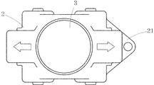
- FIG. 1 is a plan view showing a first embodiment of the present invention.
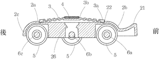
- 2 is a cross-sectional view taken along line AA in FIG.
- FIG. 3 is a front view of FIG.
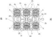
- FIG. 4 is a bottom view of FIG.
- FIG. 5 is an explanatory diagram 1 of an effect of the heavy goods moving carriage according to the present invention.
- FIG. 6 is an explanatory diagram 2 of the effect of the heavy goods moving carriage according to the present invention.
- FIG. 7 is a third explanatory diagram of effects of the heavy-duty moving carriage according to the present invention.
- FIG. 8 is an explanatory diagram 4 of the effect of the heavy goods moving carriage according to the present invention.
- FIG. 9 is an explanatory diagram of the use of the heavy goods moving carriage.
- FIG. 1 is a plan view showing a first embodiment of the present invention.
- FIG. 3 is a front view of FIG.
- FIG. 4 is a bottom view of FIG.
- FIG. 5 is an explanatory diagram 1 of an effect
- FIG. 10 is a three-dimensional perspective view of a conventional heavy goods moving carriage.
- FIG. 11 is a plan view of a conventional heavy goods moving carriage.
- FIG. 12 is a cross-sectional view of a conventional heavy goods moving carriage.
- FIG. 13 is a first problem diagram of a conventional heavy-duty moving carriage.
- FIG. 14 is a second problem diagram of the conventional heavy-duty moving carriage.
- FIG. 15 is a third problem diagram of the conventional heavy-duty moving carriage.
- FIG. 16 is a fourth problem diagram of the conventional heavy-duty moving carriage.
- FIG. 1 to FIG. 4 show an embodiment of a heavy goods moving carriage 1 according to the present invention.
- the heavy goods moving carriage 1 includes a synthetic resin carriage main body 2, a synthetic resin roller 5, metal roller shafts 6 a, 6 b, 6 c, and a load receiving platform 3 provided on the upper part of the carriage main body 2. It is a thing.
- the carriage main body 2 has a curved outer surface covering the rollers from the top plate 2a to the front and rear left and right side surfaces 2b, 2c, 2d and 2e, and a rib 2f on the bottom surface of the top plate 2a.
- a boss hole 26 penetrating vertically is provided at the center.
- the recessed surface 22 holding the load receiving platform 3 is provided in the upper surface of the top plate 2a, and the lower surface is opening.
- the rib 2f provided on the lower surface of the top plate 2a is integrally formed in a honeycomb shape from the boss hole 26 portion in the center of the carriage body 2 to the front and rear side surfaces 2b, 2c, 2d and 2e. Furthermore, 12 bearing portions 25 that support the roller shafts 6a, 6b, and 6c are provided on the front and rear, left and right side surfaces 2d and 2e, and the rib 2f, and the roller 5 is disposed so as to be supported by 6 portions. Yes.
- the load receiving platform 3 has a flat surface portion 4 at the center, and an elastic member between the flat surface outer peripheral end 3b and the load receiving outer periphery 3a forms a tapered portion, and the tapered portion is at the center. It is formed in a wave shape so that the elastic force gradually decreases from the portion toward the outer peripheral portion, and the load receiving platform outer peripheral end 3 a abuts on the receiving portion 22 of the cart main body 2 and is placed on the cart main body 2.
- urethane or the like for increasing the friction coefficient is applied to the upper surface of the flat portion 4 at the center.
- the outer peripheral end 3 a abuts against the concave body 22 of the vehicle body 2 and is supported by the cart body 2, and the flat surface portion 4 is attached to the cart body 2 via an elastic member.
- an expansion / contraction function is provided while the inclination angle is freely movable, and the flat portion 4 moves smoothly while abutting against the bottom surface of the heavy object 10.
- rollers 5 are supported by the roller shaft 6a at the front portion of the cart body 2, four are supported by the roller shaft 6c at the rear portion, and four are supported by the roller shaft 6b at the middle portion of the front and rear shafts.
- the intermediate shaft 6b is disposed below the central portion of the plane portion 4. In the case of a heavy load truck with a small load, the number of rollers 5 may be two.
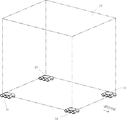
- the heavy goods moving carts 1a, 1b, 1c, and 1d are inserted into the bottom surface of the heavy goods 10 such as furniture, and the heavy goods moving carts 1a, 1b, 1c, and 1d are connected to the heavy objects.
- the heavy-duty moving carriage 1a is struck by the distortion and indentation of the floor, and as shown in FIGS. 5 (b) and 6 (a) (b), it is inclined to the floor and the bottom of the heavy object.
- the load position W from the heavy object 10 may be largely deviated from the center of the heavy object moving carriage, or the bottom surface and the floor surface of the heavy object 10 as shown in FIGS. 5 (c) and 6 (c).
- the center plane portion 4 of the load receiving platform 3 placed on the heavy load moving carriage 1a is heavy even if the distance between them increases so that the load from the heavy load 10 is not applied to the heavy moving carriage 1a. 10 so that it does not move away from and contact with the bottom surface of the object 10 while expanding and contracting while freely moving the inclination angle.
- Always be capable of holding the central flat portion 4 of the loading platform 3 receives the load of the heavy moving bogie 1a loads.
- the heavy goods moving trolley 1a of the present invention stabilizes the heavy goods while always trying to receive a load in the vicinity of the center of the heavy goods moving trolley 1a without leaving the bottom surface and the floor surface of the heavy goods 10 in contact with each other. I can support it. This is an effect that is also applicable to the other heavy goods moving carts 1b, 1c, and 1d.
- the heavy goods moving carriage 1 has a plate-to-plate joint groove G when the floor F that moves the heavy goods 10 such as furniture is flooring.
- a joint groove G is encountered.
- the roller 5 supported by the front shaft 6a reaches the groove G and falls into the groove G.
- the load point W applied to the load receiving platform 3 naturally moves slightly backward from the center of the loading platform, and the heavy load moving cart 1 moves toward the forward leaning posture.
- the load is held by the roller 5 supported by the intermediate shaft 6b and the rear shaft 6c, and the roller 5 supported by the front shaft 6a does not fall into the groove G.
- the load applied to the load receiving platform 3 is supported by the front shaft 6a and the rear shaft 6c. Held by the roller 5 and does not fall into the groove G. Further, when the roller 5 supported by the rear shaft 6c is on the groove G as shown in FIG. 7C, the load point W applied to the load receiving platform 3 is slightly forward from the center of the platform. The load from the heavy object 10 is held by the roller 5 supported by the intermediate shaft 6b and the front shaft 6a, and the roller 5 supported by the rear shaft 6c does not fall into the groove G. The heavy goods moving cart 1 can move smoothly.
- the heavy article moving carriage 1 of the present invention receives a load W from the heavy article 10. Since the roller 5 supported by the intermediate shaft 6b holds almost half of the load Wb, the load Wa applied to the front shaft roller 5 facing the step H is less, and the heavy goods moving carriage 1 is climbed over the step H. Therefore, the resistance P received to move forward is small. Further, the resin cart body 2 is elastic, and the resistance received by the front shaft roller 5 is absorbed even when the cart body 2 is slightly bent and bowed around the intermediate shaft 6b.
- the heavy goods moving cart 1 of the present invention has dramatically improved the running performance against the distortion and roughness of the floor surface and the level difference, and even if a roller having a smaller diameter is adopted as compared with the conventional cart, the running performance is improved. There is no reduction, and it is possible to provide a heavy goods moving cart that is significantly smaller and lower in weight than conventional carts.
Landscapes
- Engineering & Computer Science (AREA)
- Mechanical Engineering (AREA)
- Chemical & Material Sciences (AREA)
- Combustion & Propulsion (AREA)
- Transportation (AREA)
- Handcart (AREA)
Priority Applications (6)
| Application Number | Priority Date | Filing Date | Title |
|---|---|---|---|
| CA2866240A CA2866240C (fr) | 2012-07-12 | 2013-02-25 | Chariot robuste |
| AU2013288062A AU2013288062B2 (en) | 2012-07-12 | 2013-02-25 | Heavy object movement platform truck |
| DK13817363.8T DK2813410T3 (en) | 2012-07-12 | 2013-02-25 | Platform truck for moving heavy objects |
| ES13817363.8T ES2577285T3 (es) | 2012-07-12 | 2013-02-25 | Carro con plataforma para desplazar objetos pesados |
| EP13817363.8A EP2813410B1 (fr) | 2012-07-12 | 2013-02-25 | Chariot à plateforme de déplacement d'objets lourds |
| US14/355,822 US9027942B2 (en) | 2012-07-12 | 2013-02-25 | Heavy duty carriage cart |
Applications Claiming Priority (2)
| Application Number | Priority Date | Filing Date | Title |
|---|---|---|---|
| JP2012-156837 | 2012-07-12 | ||
| JP2012156837A JP5187605B1 (ja) | 2012-07-12 | 2012-07-12 | 重量物移動台車 |
Publications (1)
| Publication Number | Publication Date |
|---|---|
| WO2014010264A1 true WO2014010264A1 (fr) | 2014-01-16 |
Family
ID=48481437
Family Applications (1)
| Application Number | Title | Priority Date | Filing Date |
|---|---|---|---|
| PCT/JP2013/054678 Ceased WO2014010264A1 (fr) | 2012-07-12 | 2013-02-25 | Chariot à plateforme de déplacement d'objets lourds |
Country Status (8)
| Country | Link |
|---|---|
| US (1) | US9027942B2 (fr) |
| EP (1) | EP2813410B1 (fr) |
| JP (1) | JP5187605B1 (fr) |
| AU (1) | AU2013288062B2 (fr) |
| CA (1) | CA2866240C (fr) |
| DK (1) | DK2813410T3 (fr) |
| ES (1) | ES2577285T3 (fr) |
| WO (1) | WO2014010264A1 (fr) |
Cited By (1)
| Publication number | Priority date | Publication date | Assignee | Title |
|---|---|---|---|---|
| JP2015199401A (ja) * | 2014-04-07 | 2015-11-12 | 光男 長谷川 | 重量物移動台車 |
Families Citing this family (26)
| Publication number | Priority date | Publication date | Assignee | Title |
|---|---|---|---|---|
| US20130325670A1 (en) | 2012-05-30 | 2013-12-05 | Liberty Hardware Mfg. Corp. | Shower door assembly display and retail |
| US10227080B2 (en) * | 2013-09-12 | 2019-03-12 | Workshops for Warriors | Transporting loads on support surfaces |
| USD709363S1 (en) | 2014-01-29 | 2014-07-22 | Liberty Hardware Mfg. Corp. | Handle packaging |
| USD763023S1 (en) | 2014-01-29 | 2016-08-09 | Liberty Hardware Mfg. Corp. | Shower door display |
| USD767380S1 (en) * | 2014-01-29 | 2016-09-27 | Liberty Hardware Mfg. Corp. | Packaging castors |
| USD758771S1 (en) | 2014-01-29 | 2016-06-14 | Liberty Hardware Mfg. Corp. | Shower door display |
| US9676543B2 (en) | 2014-01-29 | 2017-06-13 | Liberty Hardware Mfg. Corp. | Shower door glass pane packaging assembly |
| US10070739B2 (en) | 2014-01-29 | 2018-09-11 | Liberty Hardware Mfg. Corp. | Shower door assembly display |
| US9907415B2 (en) * | 2015-03-13 | 2018-03-06 | Liberty Hardware Mfg. Corp. | Article divider assembly |
| USD777564S1 (en) | 2015-03-13 | 2017-01-31 | Liberty Hardware Mfg. Corp. | Carton divider |
| US9743810B2 (en) | 2015-07-31 | 2017-08-29 | Liberty Hardware Mfg. Corp. | Shower door guide assembly |
| JP6711665B2 (ja) * | 2016-03-29 | 2020-06-17 | ジー・オー・ピー株式会社 | 運搬台車 |
| AU2017213537A1 (en) * | 2016-08-31 | 2018-03-15 | Mammoth Industries Pty Ltd | Sliding panel wheel assembly |
| US10053129B1 (en) * | 2017-02-07 | 2018-08-21 | Eddie Lee Turner, JR. | Adjustable all-terrain dolly system and method |
| CA3076332A1 (fr) | 2018-07-30 | 2020-02-06 | Eddie Lee Turner, Jr. | Chariot de plateforme tout terrain |
| CA186586S (en) * | 2019-03-15 | 2020-09-03 | Parkit360 Inc | Powered dolly |
| CN110104041B (zh) * | 2019-05-14 | 2024-06-04 | 中国三冶集团有限公司 | 一种电机拖运装置及其使用方法 |
| CN111801261B (zh) | 2019-07-10 | 2021-08-06 | 长谷川光男 | 重物移动台车 |
| JP6664610B1 (ja) * | 2019-07-10 | 2020-03-13 | 光男 長谷川 | 重量物移動台車 |
| USD965245S1 (en) * | 2019-07-18 | 2022-09-27 | Parkit 360, Inc. | Powered dolly |
| US11554802B2 (en) | 2020-04-27 | 2023-01-17 | Midwest Innovative Products | Dolly |
| JP2020125116A (ja) * | 2020-05-28 | 2020-08-20 | ジー・オー・ピー株式会社 | 運搬台車 |
| CN112722031B (zh) * | 2021-01-23 | 2022-04-12 | 佛山民宇电子科技有限公司 | 一种可折叠式便于电路板的运输装置 |
| CN112850541B (zh) * | 2021-02-03 | 2022-10-25 | 陈火平 | 一种机械设备吊装装置 |
| JP7270129B1 (ja) | 2022-10-06 | 2023-05-10 | 光男 長谷川 | 重量物移動台車 |
| KR102678186B1 (ko) * | 2023-10-13 | 2024-06-24 | 윤삼섭 | 중량물 운반 롤러 장치 |
Citations (5)
| Publication number | Priority date | Publication date | Assignee | Title |
|---|---|---|---|---|
| JPS62121162U (fr) * | 1986-01-24 | 1987-07-31 | ||
| JPH0239960U (fr) * | 1988-09-09 | 1990-03-19 | ||
| JPH0351835U (fr) | 1989-09-26 | 1991-05-20 | ||
| JPH11152764A (ja) * | 1997-11-19 | 1999-06-08 | Takeda Seisakusho:Kk | マンホール蓋及びその運搬車 |
| JP2010143419A (ja) | 2008-12-19 | 2010-07-01 | Taiyo Seiko Kk | 重量物移動台車 |
Family Cites Families (18)
| Publication number | Priority date | Publication date | Assignee | Title |
|---|---|---|---|---|
| US171367A (en) * | 1875-12-21 | Improvement in trucks | ||
| LU39736A1 (fr) * | 1961-02-03 | 1961-04-04 | ||
| US3137512A (en) * | 1961-08-11 | 1964-06-16 | Carpezzi Leo Joseph | Height adjustable dolly |
| US3411802A (en) * | 1967-01-03 | 1968-11-19 | Montgomery Ward & Co Inc | Dolly |
| JPS4829551U (fr) | 1971-08-13 | 1973-04-11 | ||
| JPS4829561U (fr) * | 1971-08-16 | 1973-04-11 | ||
| US3948538A (en) * | 1975-06-16 | 1976-04-06 | Harry Hovila | Self equalizing ball caster lift mat |
| JP3051835U (ja) | 1998-02-26 | 1998-09-02 | 康裕 鈴木 | 重量物移動台車 |
| DE29818496U1 (de) * | 1998-10-16 | 1998-12-17 | Josef Heiss Medizintechnik GmbH, 78532 Tuttlingen | Gerätewagen |
| JP3482463B2 (ja) * | 2000-12-15 | 2003-12-22 | 矢崎化工株式会社 | 潜行型の誘導式牽引車 |
| JP2002211720A (ja) * | 2001-01-10 | 2002-07-31 | Ota Giken:Kk | 重量物搬送用自走台ローラー |
| DE20109183U1 (de) * | 2001-06-01 | 2001-08-23 | Heinrich, Hans-Jürgen, 72827 Wannweil | Transport- und Arbeitswagen, insbesondere für Farbeimer |
| US7140622B1 (en) * | 2003-03-25 | 2006-11-28 | Cantu Richard A | Movie camera skate dolly |
| US7226264B2 (en) * | 2003-09-03 | 2007-06-05 | The Boeing Company | Seat gantry |
| US7600767B2 (en) * | 2007-01-18 | 2009-10-13 | Carl Lewis | Dolly for moving large and heavy objects |
| US8302934B1 (en) * | 2009-07-03 | 2012-11-06 | Woods Steven L | Vehicle stop device |
| US8616564B2 (en) * | 2009-12-07 | 2013-12-31 | Paceco Corp. | Cargo container handling cart and system using same |
| GB2485599A (en) * | 2010-11-20 | 2012-05-23 | Steven Bowman | Chiminea wheeled base |
-
2012
- 2012-07-12 JP JP2012156837A patent/JP5187605B1/ja active Active
-
2013
- 2013-02-25 CA CA2866240A patent/CA2866240C/fr not_active Expired - Fee Related
- 2013-02-25 WO PCT/JP2013/054678 patent/WO2014010264A1/fr not_active Ceased
- 2013-02-25 DK DK13817363.8T patent/DK2813410T3/en active
- 2013-02-25 US US14/355,822 patent/US9027942B2/en active Active
- 2013-02-25 EP EP13817363.8A patent/EP2813410B1/fr active Active
- 2013-02-25 AU AU2013288062A patent/AU2013288062B2/en not_active Ceased
- 2013-02-25 ES ES13817363.8T patent/ES2577285T3/es active Active
Patent Citations (5)
| Publication number | Priority date | Publication date | Assignee | Title |
|---|---|---|---|---|
| JPS62121162U (fr) * | 1986-01-24 | 1987-07-31 | ||
| JPH0239960U (fr) * | 1988-09-09 | 1990-03-19 | ||
| JPH0351835U (fr) | 1989-09-26 | 1991-05-20 | ||
| JPH11152764A (ja) * | 1997-11-19 | 1999-06-08 | Takeda Seisakusho:Kk | マンホール蓋及びその運搬車 |
| JP2010143419A (ja) | 2008-12-19 | 2010-07-01 | Taiyo Seiko Kk | 重量物移動台車 |
Non-Patent Citations (1)
| Title |
|---|
| See also references of EP2813410A4 |
Cited By (1)
| Publication number | Priority date | Publication date | Assignee | Title |
|---|---|---|---|---|
| JP2015199401A (ja) * | 2014-04-07 | 2015-11-12 | 光男 長谷川 | 重量物移動台車 |
Also Published As
| Publication number | Publication date |
|---|---|
| CA2866240A1 (fr) | 2014-01-16 |
| DK2813410T3 (en) | 2016-06-27 |
| JP2014019195A (ja) | 2014-02-03 |
| ES2577285T3 (es) | 2016-07-14 |
| EP2813410B1 (fr) | 2016-04-20 |
| EP2813410A4 (fr) | 2015-04-08 |
| AU2013288062B2 (en) | 2015-02-05 |
| EP2813410A1 (fr) | 2014-12-17 |
| AU2013288062A1 (en) | 2014-08-28 |
| US9027942B2 (en) | 2015-05-12 |
| US20140290001A1 (en) | 2014-10-02 |
| JP5187605B1 (ja) | 2013-04-24 |
| CA2866240C (fr) | 2015-04-28 |
Similar Documents
| Publication | Publication Date | Title |
|---|---|---|
| JP5187605B1 (ja) | 重量物移動台車 | |
| US7104524B1 (en) | Vehicle ramp with chock | |
| JP5246620B2 (ja) | 重量物移動台車 | |
| US7770903B2 (en) | Drawer type storage cart | |
| US6908088B2 (en) | Wheelbarrow bumper | |
| US7207578B2 (en) | Dolly for dock plates | |
| JP2021014143A (ja) | 重量物移動台車 | |
| JP6882804B2 (ja) | 階段スリップ防止のための階段昇降用自動運搬台車 | |
| JP2015024800A (ja) | 重量物移動台車 | |
| CN111801261B (zh) | 重物移动台车 | |
| KR200494623Y1 (ko) | 캐스터 및 그를 갖는 손수레 | |
| US11760585B2 (en) | Momentum arresting ramp | |
| US8607411B2 (en) | Combination of carpet-cleaning machine and platform for transporting the machine | |
| KR200387551Y1 (ko) | 다용도 사다리 | |
| JP6171195B1 (ja) | 重量物移動台車 | |
| JP7270129B1 (ja) | 重量物移動台車 | |
| JP5617088B1 (ja) | 重量物移動台車 | |
| JP2017200778A (ja) | 重量物移動台車 | |
| JP2017128142A (ja) | 固定装置 | |
| JP5165848B2 (ja) | 収納システム | |
| KR20200002491U (ko) | 바퀴가 구비된 휴대형 운반 부재 | |
| JP6795156B2 (ja) | 床材剥離機における床材剥離機用補助台車の取り付け方法 | |
| JP3122069U (ja) | 転倒防止家具及び転倒防止装置 | |
| JP2019126809A (ja) | 載置物転倒防止装置 | |
| JPH07267093A (ja) | 台 車 |
Legal Events
| Date | Code | Title | Description |
|---|---|---|---|
| 121 | Ep: the epo has been informed by wipo that ep was designated in this application |
Ref document number: 13817363 Country of ref document: EP Kind code of ref document: A1 |
|
| WWE | Wipo information: entry into national phase |
Ref document number: 14355822 Country of ref document: US |
|
| WWE | Wipo information: entry into national phase |
Ref document number: 2013817363 Country of ref document: EP |
|
| ENP | Entry into the national phase |
Ref document number: 2013288062 Country of ref document: AU Date of ref document: 20130225 Kind code of ref document: A |
|
| ENP | Entry into the national phase |
Ref document number: 2866240 Country of ref document: CA |
|
| NENP | Non-entry into the national phase |
Ref country code: DE |