WO2014010378A1 - ゴムクローラ - Google Patents
ゴムクローラ Download PDFInfo
- Publication number
- WO2014010378A1 WO2014010378A1 PCT/JP2013/066761 JP2013066761W WO2014010378A1 WO 2014010378 A1 WO2014010378 A1 WO 2014010378A1 JP 2013066761 W JP2013066761 W JP 2013066761W WO 2014010378 A1 WO2014010378 A1 WO 2014010378A1
- Authority
- WO
- WIPO (PCT)
- Prior art keywords
- rubber
- crawler
- circumferential
- wall surface
- wheel
- Prior art date
- Legal status (The legal status is an assumption and is not a legal conclusion. Google has not performed a legal analysis and makes no representation as to the accuracy of the status listed.)
- Ceased
Links
Images


Classifications
-
- B—PERFORMING OPERATIONS; TRANSPORTING
- B62—LAND VEHICLES FOR TRAVELLING OTHERWISE THAN ON RAILS
- B62D—MOTOR VEHICLES; TRAILERS
- B62D55/00—Endless track vehicles
- B62D55/08—Endless track units; Parts thereof
- B62D55/18—Tracks
- B62D55/24—Tracks of continuously flexible type, e.g. rubber belts
- B62D55/244—Moulded in one piece, with either smooth surfaces or surfaces having projections, e.g. incorporating reinforcing elements
Definitions
- the present invention relates to a rubber crawler.
- a rubber crawler there is a type of rubber crawler in which a driving force is transmitted by abutment of pins provided on a driving wheel on the airframe side with rubber protrusions provided at a constant pitch on an inner peripheral surface (for example, JP, 2000-33889, A).
- a substantially cylindrical wear-resistant member extending in the crawler width direction is embedded in the rubber protrusion. Both ends of the wear-resistant member are exposed from the side walls of the rubber protrusions, and wear of the side walls of the rubber protrusions can be suppressed by coming into contact with the underbody parts on the airframe side such as drive wheels.
- An object of the present invention is to suppress the concentration of strain around an embedded member embedded in a rubber protrusion.
- the rubber crawler includes an endless rubber body wound around a drive wheel, and a plurality of rubber bodies provided on the rubber body at intervals in the circumferential direction of the rubber body.
- the rubber crawler of the present invention can suppress the concentration of strain around the embedded member embedded in the rubber protrusion.
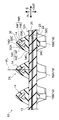
- FIG. 5 is a sectional view taken along line 5X-5X in FIG. 4. It is the sectional side view which cut
- the endless rubber crawler 10 as an example of the rubber crawler according to the first embodiment is a so-called coreless-less type rubber crawler having no cored bar.
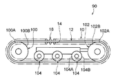
- the rubber crawler 10 is used by being wound around a drive wheel 100 connected to a drive shaft of a crawler wheel as a machine body and an idler wheel 102 rotatably attached to the crawler wheel.
- a plurality of rolling wheels 104 disposed between the driving wheel 100 and the idler wheel 102 and rotatably attached to the crawler wheel roll on the inner periphery of the rubber crawler 10.
- the driving wheel 100, the idler wheel 102, and the rolling wheel 104 will be appropriately described as wheels that are suspension parts on the airframe side.
- the circumferential direction of the endless rubber crawler 10 (direction of arrow S in FIGS. 3 and 4) is referred to as “crawler circumferential direction”, and the width direction of the rubber crawler 10 (arrow W in FIGS. 3 and 4). (Direction) is described as “crawler width direction”.
- the crawler circumferential direction and the crawler width direction are orthogonal to each other when the rubber crawler 10 is viewed from the outer peripheral side or the inner peripheral side.
- the inner peripheral side (the arrow IN direction side in FIGS. 5 and 6) of the rubber crawler 10 that is wound around the driving wheel 100, the idler wheel 102, and the roller wheel 104 is an “inside of the crawler”.
- the outer peripheral side of the rubber crawler 10 (the arrow OUT direction side in FIGS. 5 and 6) is referred to as the “crawler outer peripheral side”. 5 and 6, an arrow IN direction (annular inner direction) and an arrow OUT direction (annular outer direction) indicate the inner and outer directions of the rubber crawler 10 in a wound state (in other words, the thickness direction of the rubber crawler 10). ).
- the rubber crawler 10 is wound around the driving wheel 100 and the idler wheel 102.
- the present invention is not limited to this configuration, and the driving wheel 100, the idler wheel 102, and the plurality of wheel 104.
- the rubber crawler 10 may be wound around one or a plurality of rolling wheels 104 in addition to the driving wheel 100 and the idle wheel 102.
- a crawler traveling device 90 is configured.
- the drive wheel 100 has a pair of disc-shaped wheel portions 100A connected to the drive shaft of the crawler wheel.
- the ring portion 100A rolls while the outer peripheral surface 100B comes into contact with a wheel rolling surface 16 of a rubber crawler 10 described later.
- columnar engagement pins 101 are formed at regular intervals in the circumferential direction so as to span between the peripheral portions of the pair of ring portions 100A.
- the engaging pin 101 is adapted to engage with a rubber protrusion 14 described later, and the rubber protrusion 14 (specifically, the circumferential rubber wall surface of the rubber protrusion 14 in the crawler circumferential direction). 14A), the driving force from the crawler wheel is transmitted (input) to the rubber crawler 10.
- the rubber crawler 10 to which the driving force is thus transmitted circulates between the driving wheel 100 and the idler wheel 102. Then, by the circulation of the rubber crawler 10, a lug 18 described later catches the ground, and the crawler vehicle having the crawler traveling device 90 moves (runs).
- the idler wheel 102 has a pair of disc-shaped wheel portions 102A that are rotatably attached to the crawler wheel.
- the ring portion 102A has an outer peripheral surface 102B that comes into contact with a wheel rolling surface 16 of a rubber crawler 10 described later.
- the idler wheel 102 is pressed in a direction away from the drive wheel 100 by a pressurizing mechanism such as hydraulic pressure (not shown) provided on the crawler vehicle side and is pressed against the wheel rolling surface 16 of the rubber crawler 10 to tension the rubber crawler 10. (Tension) is maintained.
- the wheel 104 supports the weight of the crawler wheel, and has a disc-shaped wheel portion 104A that is rotatably attached to the crawler wheel.
- a disc-shaped wheel portion 104A that is rotatably attached to the crawler wheel.
- an outer peripheral surface 104B comes into contact with a wheel rolling surface 16 of a rubber crawler 10 described later.
- the idler wheel 102 and the rolling wheel 104 are driven to rotate with respect to the rubber crawler 10 circulating between the drive wheel 100 and the idler wheel 102.
- the rubber crawler 10 has a rubber belt 12 in which a rubber material is formed in an endless belt shape.
- the rubber belt 12 of the present embodiment is an example of an endless rubber body of the present invention.
- the circumferential direction, the width direction, the inner circumferential side, and the outer circumferential side of the rubber belt 12 of the present embodiment coincide with the crawler circumferential direction, the crawler width direction, the crawler inner circumferential side, and the crawler outer circumferential side, respectively.
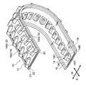
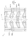
- a plurality of rubber protrusions 14 projecting toward the inner periphery of the crawler are formed on the inner periphery of the rubber belt 12 at intervals in the crawler peripheral direction.
- the rubber protrusion 14 is disposed at the center of the rubber belt 12 in the crawler width direction, and extends in the crawler width direction of wheels (driving wheels 100, idle wheels 102, and rolling wheels 104) that roll on a wheel rolling surface 16 described later. Is restricted by contact.
- the rubber protrusions 14 can limit relative displacement of the wheels and the rubber crawler 10 (rubber belt 12) in the crawler width direction by contacting the wheels.
- the side surface portion of the wheel comes into contact with the width direction rubber wall surface 14B of the rubber protrusion 14 in the crawler width direction.
- wheel rolling surfaces 16 extending along the crawler circumferential direction are formed on both sides in the crawler width direction across the rubber protrusion 14 of the rubber belt 12, respectively.
- the wheel rolling surface 16 is flat and constitutes a part of the inner peripheral surface 12A of the rubber belt 12.
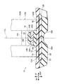
- a block-shaped lug 18 is formed on the outer periphery of the rubber belt 12 so as to protrude to the outer periphery of the crawler and to contact the ground.
- the lug 18 is composed of a pair of lugs 18A arranged on the left and right sides of the center line CL, and a pair of lugs 18B arranged so as to cross the center line CL.
- the lugs 18A and lugs 18B are alternately formed in the crawler circumferential direction. Further, both the lug 18A and the lug 18B are arranged so as to partially overlap the crawler outer peripheral side of the rubber protrusion 14.
- an endless belt-like main cord layer 20 extending in the crawler circumferential direction is embedded in the rubber belt 12.
- the main cord layer 20 is formed by rubber-coating one main cord spirally wound along the crawler circumferential direction or a plurality of reinforcing cords arranged along the crawler circumferential direction and arranged in parallel in the crawler width direction. Formed.
- a steel cord having excellent tensile strength is used as the main cord.
- the present invention is not limited to this configuration.
- an organic fiber may be used as long as it has sufficient tensile strength.
- a code may be used as the main code.
- Bias cord layers 22 and 23 are embedded in the crawler outer peripheral side of the main cord layer 20 of the rubber belt 12, respectively.
- the bias cord layers 22 and 23 are formed by arranging bias cords extending obliquely with respect to the crawler circumferential direction in parallel with each other and burying them in a belt-like rubber material. Further, the bias code of the bias code layer 22 and the bias code of the bias code layer 23 extend in opposite directions with respect to the center line CL.
- steel cords having excellent tensile strength are used as the bias cords of the bias cord layers 22 and 23.
- the present invention is not limited to this configuration and may have sufficient tensile strength.
- a cord made of organic fiber or the like may be used as the bias cord.
- the rubber protrusion 14 has a mountain shape that becomes wider from the top portion 14D to the root portion 14C when viewed from the crawler width direction.
- the circumferential rubber wall surface 14A of the rubber protrusion 14 of the present embodiment is inclined in multiple stages (two stages) with respect to the crawler thickness direction (thickness direction of the rubber crawler 10). That is, the circumferential rubber wall surface 14A is composed of an inclined portion 14E on the base portion 14C side and an inclined portion 14F on the top portion 14D side. The inclination angle of the inclined portion 14E with respect to the crawler thickness direction is set smaller than that of the inclined portion 14F.
- the present invention is not limited to this configuration, and the circumferential rubber wall surface 14A may be inclined in a straight line with respect to the crawler thickness direction without being inclined in multiple stages.
- an embedded member 30 is embedded in the rubber protrusion 14.
- the embedded member 30 extends in the crawler width direction, and both end portions 30B are exposed from both width direction rubber wall surfaces 14B of the rubber protrusions 14 (see FIGS. 2 and 5).
- the end portion 30B which is the exposed portion of the embedded member 30, abuts against the side surface portion of the wheel together with the width direction rubber wall surface 14B of the rubber protrusion 14, thereby suppressing wear of the width direction rubber wall surface 14B of the rubber protrusion 14. Can do.
- both end portions 30B of the embedded member 30 are exposed from both width direction rubber wall surfaces 14B of the rubber protrusions 14, but the present invention is not limited to this configuration, and both end portions 30B of the embedded member 30 are exposed. May not be exposed from the rubber wall surfaces 14B in the width direction of the rubber protrusions 14.
- the embedded member 30 is formed of a resin material having higher wear resistance than the rubber material constituting the rubber protrusion 14.
- this resin material one having high mechanical strength is preferable, and examples thereof include ultra high molecular weight polyethylene and polyamide resin.
- the embedded member 30 is formed of a polyamide resin.
- the embedded member 30 is formed of a resin material, but the present invention is not limited to this configuration, and a metal material may be used.
- the embedded member 30 has a circumferential wall surface 30A in the crawler circumferential direction as viewed in a cross section along the crawler circumferential direction (hereinafter referred to as “crawler circumferential cross section” as appropriate).
- the circumferential wall surface 30A is along the circumferential rubber wall surface 14A” means that the distance between the circumferential wall surface 30A and the circumferential rubber wall surface 14A is substantially equal when viewed in the crawler circumferential section.
- the circumferential wall surface 30A is inclined with respect to the crawler thickness direction.
- the circumferential wall surface 30A is along the circumferential rubber wall surface 14A
- one wall surface is a flat surface and the other wall surface is a curved surface, or one wall surface is inclined in multiple stages.
- the case where the other wall surface is a flat surface or a curved surface, and the case where both wall surfaces are flat surfaces, curved surfaces, or inclined surfaces inclined in multiple stages are also included.
- the circumferential wall surface 30A is along the circumferential rubber wall surface 14A” includes the case where the circumferential wall surface 30A and the circumferential rubber wall surface 14A are parallel.
- the rubber thickness between the circumferential wall surface 30A and the circumferential rubber wall surface 14A is substantially equal when viewed in the crawler circumferential section.
- the rubber thickness between the circumferential wall surface 30A and the circumferential rubber wall surface 14A is substantially equal over the entire circumferential wall surface 30A.
- the circumferential wall surface 30A is an inclined plane that is inclined with respect to the crawler thickness direction.
- this invention is not limited to the said structure, 30 A of circumferential wall surfaces may be a curved surface which inclines while curving with respect to the crawler thickness direction.
- the circumferential wall surface 30A is parallel to the straight line SL passing through the starting point X and the ending point Y of the circumferential rubber wall surface 14A of the rubber projection 14 when viewed in the crawler circumferential section. It has become.
- the embedded member 30 has a triangular shape when viewed in the crawler circumferential cross section. More specifically, the embedded member 30 has a crawler circumferential cross-sectional shape that is triangular, and a triangular corner 30C is curved in an arc shape.
- the present invention is not limited to this configuration, and the cross-sectional shape of the embedded member 30 may be a polygonal shape such as a trapezoidal shape.
- the embedded member 30 is arranged on a bisector PL where the center (center of gravity) P bisects the rubber protrusion 14 in the crawler circumferential direction in a cross section along the crawler circumferential direction. ing. That is, the embedded member 30 is symmetrical with respect to the bisector PL.
- the height H1 of the center P of the embedded member 30 is set in the range of 15.2 to 60.1% of the height H0 of the rubber protrusion 14.
- the height H0 of the rubber protrusion 14 is measured along the crawler thickness direction from the inner peripheral surface 12A of the rubber belt 12 to the top 14D of the rubber protrusion 14, and the height H1 of the center P of the embedded member 30 is Measured from the inner peripheral surface 12A to the center P of the rubber belt 12 along the crawler thickness direction.
- the length L from the center P of the embedded member 30 to the vertex Z of the corner portion 30C is set within a range of 30.3 to 39% of the height H of the rubber protrusion 14. Note that, as shown in FIG. 7B, the vertex Z of the corner portion 30 ⁇ / b> C is an intersection of the extension lines of each side of the embedded member 30.
- the rubber protrusion 14 and the embedded member 30 are generally similar in shape when viewed in the crawler circumferential cross section.
- the engaging pin 101 of the driving wheel 100 engages with the circumferential rubber wall surface 14 ⁇ / b> A of the rubber protrusion 14, and the driving force F is input to the rubber protrusion 14.
- the circumferential wall surface 30A of the embedded member 30 embedded in the rubber protrusion 14 as seen in the crawler circumferential section is along the circumferential rubber wall surface 14A, that is, the rubber thickness of the portion corresponding to the circumferential wall surface 30A is Since they are substantially equal, the input from the engagement pin 101 is received in a wide range by the circumferential wall surface 30 ⁇ / b> A of the embedded member 30. Thereby, it can suppress that distortion concentrates around the embedding member 30 of the rubber protrusion 14.
- FIG. 7A the engaging pin 101 of the driving wheel 100 engages with the circumferential rubber wall surface 14 ⁇ / b> A of the rubber protrusion 14, and the driving force F is input to the rubber protrusion 14.
- the embedded member 30 is embedded, the bending rigidity of the rubber protrusion 14 is improved, so that the elastic deformation of the rubber protrusion 14 so as to fall due to the input from the engagement pin 101 is suppressed.
- the side surface portion of the drive wheel 100 comes into contact with the width direction rubber wall surface 14B of the rubber protrusion 14 and the end portion 30B of the embedded member 30 exposed from the width direction rubber wall surface 14B.
- the relative displacement in the crawler width direction between the wheel 100 and the rubber belt 12 can be limited.
- the embedded member 30 is formed of a resin material having higher wear resistance than the rubber protrusion 14, it is possible to suppress wear of the width direction rubber wall surface 14 ⁇ / b> B of the rubber protrusion 14 due to friction with the drive wheel 100. .
- the circumferential wall surface 30 ⁇ / b> A of the embedded member 30 is an inclined flat surface that is inclined with respect to the crawler thickness direction. Can be received almost uniformly over the entire circumferential wall surface 30A of the embedded member 30.
- the embedded member 30 can be reduced in weight compared to a trapezoidal shape or other polygonal shapes. it can.
- the embedded member 30 is formed with a plurality of corner portions 30C, even if the end portion 30B receives a force in the rotational direction of the wheel due to contact with the wheel, the corner portion 30C and the surrounding rubber The movement of the embedded member 30 is suppressed by the engagement. Thereby, it is possible to suppress excessive distortion from occurring around the embedded member 30 of the rubber protrusion 14.
- the height H1 of the center P of the embedded member 30 is set within the range of 15.2 to 60.1% of the height H0 of the rubber protrusion 14, and from the center P of the embedded member 30 to the vertex Z of the corner portion 30C. Is set within the range of 30.3 to 39% of the height H of the rubber protrusion 14, it is possible to effectively suppress the concentration of strain around the embedded member 30 of the rubber protrusion 14. it can.
- the embedded member 30 has a triangular prism shape extending in the crawler width direction, but the present invention is not limited to this configuration, and a hollow portion (for example, a through hole) extending in the crawler width direction is provided in the embedded member 30. It may be formed. By setting it as the said structure, the embedding member 30 can be reduced in weight.
- a rubber belt 12 in which a rubber material is formed in an endless belt shape is used as an example of an endless rubber body (an object having rubber elasticity (that is, a rubber elastic body)) according to the present invention.
- the configuration is not limited, and an elastomer belt in which an elastomer material having rubber elasticity is formed in an endless belt shape may be used.
- the rubber crawlers of the examples included in the present invention are less strained around the embedded members of the rubber protrusions than the rubber crawlers of the comparative examples. I understand. Further, as a result of changing the height H1 and the length L of the rubber crawlers of the examples as shown in Table 2, it can be seen that all the strain values are smaller than the maximum strain of the comparative example. Accordingly, the height H1 is set in the range of 15.2 to 60.1% of the height H0 of the rubber protrusion, and the length L is set in the range of 30.3 to 39% of the height H0 of the rubber protrusion. It is preferable to do.
Landscapes
- Engineering & Computer Science (AREA)
- Chemical & Material Sciences (AREA)
- Combustion & Propulsion (AREA)
- Transportation (AREA)
- Mechanical Engineering (AREA)
- Compositions Of Macromolecular Compounds (AREA)
Description
本発明は、ゴムクローラに関するものである。
ゴムクローラとしては、内周面に一定のピッチで設けられたゴム突起に、機体側の駆動輪に設けられたピンが当接することで、駆動力が伝達されるタイプのゴムクローラがある(例えば、特開2000-33889号公報)。
特開2000-33889号公報に開示のゴムクローラでは、ゴム突起内に、クローラ幅方向に延びる略円柱状の耐摩耗性部材を埋設している。この耐摩耗性部材は、両端部がゴム突起の側壁から露出しており、駆動輪などの機体側の足回り部品と当接することで、ゴム突起の側壁の摩耗を抑制することができる。
ところで、駆動輪のピンがゴム突起に強い力で押し付けられると、円柱状の耐摩耗性部材の周りに歪みが集中する傾向がある。
本発明は、ゴム突起に埋設された埋設部材の周りに歪みが集中するのを抑制することを課題とする。
本発明の第1態様のゴムクローラは、駆動輪に巻き掛けられる無端帯状のゴム体と、前記ゴム体に該ゴム体周方向に間隔をあけて複数設けられ、ゴム体内周側に突出し、ゴム体幅方向から見て頂部から底部にかけて次第に幅広となる山形状とされ、ゴム体周方向のゴム壁面に前記駆動輪に設けられた係合ピンが係合して駆動力が入力されるゴム突起と、前記ゴム突起に埋設され、ゴム体周方向に沿った断面で見てゴム体周方向の壁面が前記ゴム壁面に沿っている埋設部材と、を有している。
以上説明したように、本発明のゴムクローラは、ゴム突起に埋設された埋設部材の周りに歪みが集中するのを抑制することができる。
(第1実施形態)
以下、本発明の第1実施形態に係るゴムクローラについて説明する。
以下、本発明の第1実施形態に係るゴムクローラについて説明する。
第1実施形態に係るゴムクローラの一例としての無端状のゴムクローラ10は、芯金をもたない、いわゆる芯金レスタイプのゴムクローラである。
図1に示すように、ゴムクローラ10は、機体としてのクローラ車の駆動軸に連結された駆動輪100とクローラ車に回転自在に取付けられた遊動輪102とに巻き掛けられて用いられる。また、ゴムクローラ10の内周を、駆動輪100と遊動輪102の間に配置され且つクローラ車に回転自在に取り付けられた複数の転輪104が転動するようになっている。
なお、以下では、駆動輪100、遊動輪102、及び転輪104をまとめて機体側の足回り部品である車輪として適宜説明する。
なお、以下では、駆動輪100、遊動輪102、及び転輪104をまとめて機体側の足回り部品である車輪として適宜説明する。
本実施形態では、無端状のゴムクローラ10の周方向(図3、図4の矢印S方向)を「クローラ周方向」と記載し、ゴムクローラ10の幅方向(図3、図4の矢印W方向)を「クローラ幅方向」と記載する。なお、クローラ周方向とクローラ幅方向は、ゴムクローラ10を外周側または内周側から見た場合に直交する。
また、本実施形態では、駆動輪100、遊動輪102、及び転輪104に巻き掛けて環状となったゴムクローラ10の内周側(図5、図6の矢印IN方向側)を「クローラ内周側」と記載し、上記ゴムクローラ10の外周側(図5、図6の矢印OUT方向側)を「クローラ外周側」と記載する。なお、図5、図6の矢印IN方向(環状の内側方向)、矢印OUT方向(環状の外側方向)は、巻き掛け状態のゴムクローラ10の内外方向(換言すれば、ゴムクローラ10の厚み方向)を示している。
なお、本実施形態では、ゴムクローラ10を駆動輪100及び遊動輪102に巻き掛ける構成としているが、本発明はこの構成に限定されず、駆動輪100、遊動輪102、及び複数の転輪104の配置によっては、駆動輪100及び遊動輪102に加えて、一つまたは複数の転輪104にゴムクローラ10が巻き掛かる構成としてもよい。
また、本実施形態では、駆動輪100、遊動輪102、及び転輪104に巻き掛けて環状となったゴムクローラ10の内周側(図5、図6の矢印IN方向側)を「クローラ内周側」と記載し、上記ゴムクローラ10の外周側(図5、図6の矢印OUT方向側)を「クローラ外周側」と記載する。なお、図5、図6の矢印IN方向(環状の内側方向)、矢印OUT方向(環状の外側方向)は、巻き掛け状態のゴムクローラ10の内外方向(換言すれば、ゴムクローラ10の厚み方向)を示している。
なお、本実施形態では、ゴムクローラ10を駆動輪100及び遊動輪102に巻き掛ける構成としているが、本発明はこの構成に限定されず、駆動輪100、遊動輪102、及び複数の転輪104の配置によっては、駆動輪100及び遊動輪102に加えて、一つまたは複数の転輪104にゴムクローラ10が巻き掛かる構成としてもよい。
図1に示すように、駆動輪100、遊動輪102、転輪104、及び駆動輪100と遊動輪102に巻き掛けられたゴムクローラ10によって、クローラ車の走行部としての第1実施形態に係るクローラ走行装置90が構成されている。
図1に示すように、駆動輪100は、クローラ車の駆動軸に連結される円盤状の一対の輪部100Aを有している。この輪部100Aは、外周面100Bが後述するゴムクローラ10の車輪転動面16に接触して転動するようになっている。また、一対の輪部100Aには、互いの周縁部に架け渡されるように円柱状の係合ピン101が円周方向に一定間隔で形成されている。この係合ピン101は、図8に示すように、後述するゴム突起14に係合するようになっており、ゴム突起14(具体的には、ゴム突起14のクローラ周方向の周方向ゴム壁面14A)と係合することでクローラ車からの駆動力をゴムクローラ10に伝達(入力)するようになっている。このようにして駆動力が伝達されたゴムクローラ10は、駆動輪100及び遊動輪102の間を循環する。そして、ゴムクローラ10の循環により、後述するラグ18が地面を捉えて、クローラ走行装置90を有するクローラ車が移動(走行)する。
遊動輪102は、クローラ車に回転自在に取付けられる円盤状の一対の輪部102Aを有している。この輪部102Aは、外周面102Bが後述するゴムクローラ10の車輪転動面16に接触するようになっている。また、遊動輪102は、クローラ車側が備える図示しない油圧等の加圧機構によって駆動輪100から離間する方向へ押圧されて、ゴムクローラ10の車輪転動面16に押し付けられてゴムクローラ10のテンション(張力)を保持するものである。
転輪104は、クローラ車の重量を支持するものであり、クローラ車に回転自在に取付けられる円盤状の輪部104Aを有している。この輪部104Aは、外周面104Bが後述するゴムクローラ10の車輪転動面16に接触するようになっている。
上記遊動輪102及び転輪104は、駆動輪100及び遊動輪102の間を循環するゴムクローラ10に対して従動回転するようになっている。
図1に示すように、ゴムクローラ10は、ゴム材を無端帯状に形成したゴムベルト12を有している。なお、本実施形態のゴムベルト12は、本発明の無端状のゴム体の一例である。また、本実施形態のゴムベルト12の周方向、幅方向、内周側、外周側は、それぞれクローラ周方向、クローラ幅方向、クローラ内周側、クローラ外周側と一致している。
図1~3に示すように、ゴムベルト12の内周には、クローラ内周側に突出するゴム突起14がクローラ周方向に間隔をあけて複数形成されている。このゴム突起14は、ゴムベルト12のクローラ幅方向の中央部に配置され、後述する車輪転動面16上を転動する車輪(駆動輪100、遊動輪102、転輪104)のクローラ幅方向への移動を当接により制限するようになっている。言い換えると、ゴム突起14は、車輪と当接することで、車輪と、ゴムクローラ10(ゴムベルト12)とのクローラ幅方向の相対変位を制限することができる。
なお、本実施形態では、ゴム突起14のクローラ幅方向の幅方向ゴム壁面14Bに、車輪の側面部が当接するようになっている。
なお、本実施形態では、ゴム突起14のクローラ幅方向の幅方向ゴム壁面14Bに、車輪の側面部が当接するようになっている。
図2及び図3に示すように、ゴムベルト12のゴム突起14を挟んでクローラ幅方向両側には、クローラ周方向に沿って延びる車輪転動面16がそれぞれ形成されている。この車輪転動面16は、平坦状とされ、ゴムベルト12の内周面12Aの一部を構成している。
図4、図5に示すように、ゴムベルト12の外周には、クローラ外周側に突出し、地面と接地するブロック状のラグ18が形成されている。このラグ18は、図4に示すように、中央線CLを挟んで左右にそれぞれ配置される一対のラグ18Aと、中央線CLを横切るように配置される一対のラグ18Bとで構成されており、ラグ18Aとラグ18Bはクローラ周方向に交互に形成されている。また、ラグ18A及びラグ18Bはともに、一部がゴム突起14のクローラ外周側に重なるように配置されている。
図5、図6に示すように、ゴムベルト12には、クローラ周方向に沿って延びる無端帯状のメインコード層20が埋設されている。このメインコード層20は、クローラ周方向に沿って螺旋状に巻回された1本のメインコード又はクローラ周方向に沿い且つクローラ幅方向に並列された複数本の補強コードを、ゴム被覆して形成したものである。なお、本実施形態においては、引張り強度に優れるスチールコードをメインコードとして用いるが、本発明はこの構成に限定されず、十分な引張り強度を有していれば、例えば、有機繊維などで構成したコードをメインコードとして用いてもよい。
ゴムベルト12のメインコード層20のクローラ外周側には、バイアスコード層22、23がそれぞれ埋設されている。バイアスコード層22、23は、クローラ周方向に対して斜めに延びるバイアスコードを互いに平行に並べると共に帯状ゴム材に埋設して形成されたものである。また、バイアスコード層22のバイアスコードとバイアスコード層23のバイアスコードは、中央線CLを挟んで互いに逆向きに延びている。なお、本実施形態では、バイアスコード層22、23の各々のバイアスコードとして引張り強度に優れるスチールコードを用いているが、本発明はこの構成に限定されず、十分な引張り強度を有していれば、例えば、有機繊維などで構成したコードをバイアスコードとして用いてもよい。
次に、前述したゴム突起14及び埋設部材30について詳細に説明する。
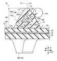
図6、図7Aに示すように、ゴム突起14は、クローラ幅方向から見て、頂部14Dから根元部14Cにかけて幅広となる山形状とされている。
また、本実施形態のゴム突起14の周方向ゴム壁面14Aは、クローラ厚み方向(ゴムクローラ10の厚み方向)に対して多段階(二段階)に傾斜している。すなわち、周方向ゴム壁面14Aは、根元部14C側の傾斜部14Eと頂部14D側の傾斜部14Fとで構成されている。この傾斜部14Eのクローラ厚み方向に対する傾斜角は、傾斜部14Fよりも小さく設定されている。なお、本発明はこの構成に限定されず、周方向ゴム壁面14Aは、多段階に傾斜せずに、クローラ厚み方向に対して一直線状に傾斜していてもよい。
図6、図7Aに示すように、ゴム突起14は、クローラ幅方向から見て、頂部14Dから根元部14Cにかけて幅広となる山形状とされている。
また、本実施形態のゴム突起14の周方向ゴム壁面14Aは、クローラ厚み方向(ゴムクローラ10の厚み方向)に対して多段階(二段階)に傾斜している。すなわち、周方向ゴム壁面14Aは、根元部14C側の傾斜部14Eと頂部14D側の傾斜部14Fとで構成されている。この傾斜部14Eのクローラ厚み方向に対する傾斜角は、傾斜部14Fよりも小さく設定されている。なお、本発明はこの構成に限定されず、周方向ゴム壁面14Aは、多段階に傾斜せずに、クローラ厚み方向に対して一直線状に傾斜していてもよい。
図5~図7Aに示すように、ゴム突起14内には、埋設部材30が埋設されている。この埋設部材30は、クローラ幅方向に延びて両端部30Bがゴム突起14の両幅方向ゴム壁面14Bからそれぞれ露出している(図2、図5参照)。この埋設部材30の上記露出部分である端部30Bは、ゴム突起14の幅方向ゴム壁面14Bと共に車輪の側面部と当接することで、ゴム突起14の幅方向ゴム壁面14Bの摩耗を抑制することができる。
なお、本実施形態では、埋設部材30の両端部30Bをゴム突起14の両幅方向ゴム壁面14Bからそれぞれ露出させているが、本発明はこの構成に限定されず、埋設部材30の両端部30Bをゴム突起14の両幅方向ゴム壁面14Bから露出させなくてもよい。
なお、本実施形態では、埋設部材30の両端部30Bをゴム突起14の両幅方向ゴム壁面14Bからそれぞれ露出させているが、本発明はこの構成に限定されず、埋設部材30の両端部30Bをゴム突起14の両幅方向ゴム壁面14Bから露出させなくてもよい。
また、埋設部材30は、ゴム突起14を構成するゴム材よりも耐摩耗性が高い樹脂材料によって形成されている。この樹脂材料としては、機械的強度が高いものが好ましく、例えば、超高分子量ポリエチレンやポリアミド系樹脂などが挙げられる。なお、本実施形態では、埋設部材30をポリアミド系樹脂で形成している。
本実施形態では、埋設部材30を樹脂材料で形成しているが、本発明はこの構成に限定されず、金属材料を用いてもよい。
図6、図7Aに示すように、埋設部材30は、クローラ周方向に沿った断面(以下、適宜「クローラ周方向断面」と記載する)で見てクローラ周方向の周方向壁面30Aが周方向ゴム壁面14Aに沿っている。
なお、ここで言う「周方向壁面30Aが周方向ゴム壁面14Aに沿っている」とは、クローラ周方向断面で見て、周方向壁面30Aと周方向ゴム壁面14Aとの間隔が概ね等しくなるように、周方向壁面30Aがクローラ厚み方向に対して傾斜していることを指している。このため、「周方向壁面30Aが周方向ゴム壁面14Aに沿っている」には、一方の壁面が平面で且つ他方の壁面が湾曲面の場合や、一方の壁面が多段階に傾斜する傾斜面で且つ他方の壁面が平面または湾曲面の場合や、両壁面が平面、湾曲面、または多段階に傾斜した傾斜面の場合も含まれる。また、「周方向壁面30Aが周方向ゴム壁面14Aに沿っている」には、周方向壁面30Aと周方向ゴム壁面14Aが平行な場合も含まれる。
なお、ここで言う「周方向壁面30Aが周方向ゴム壁面14Aに沿っている」とは、クローラ周方向断面で見て、周方向壁面30Aと周方向ゴム壁面14Aとの間隔が概ね等しくなるように、周方向壁面30Aがクローラ厚み方向に対して傾斜していることを指している。このため、「周方向壁面30Aが周方向ゴム壁面14Aに沿っている」には、一方の壁面が平面で且つ他方の壁面が湾曲面の場合や、一方の壁面が多段階に傾斜する傾斜面で且つ他方の壁面が平面または湾曲面の場合や、両壁面が平面、湾曲面、または多段階に傾斜した傾斜面の場合も含まれる。また、「周方向壁面30Aが周方向ゴム壁面14Aに沿っている」には、周方向壁面30Aと周方向ゴム壁面14Aが平行な場合も含まれる。
上記構成により、クローラ周方向断面で見て周方向壁面30Aと周方向ゴム壁面14Aとの間のゴム厚みが概ね等しくなっている。なお、本実施形態では、周方向壁面30Aと周方向ゴム壁面14Aとの間のゴム厚みが周方向壁面30A全体にわたって概ね等しくなっている。
また、本実施形態では、周方向壁面30Aは、クローラ厚み方向に対して傾斜する傾斜平面とされている。なお、本発明は上記構成に限定されず、周方向壁面30Aは、クローラ厚み方向に対して湾曲しながら傾斜する湾曲面でもよい。
またさらに、本実施形態では、周方向壁面30Aは、クローラ周方向断面で見てゴム突起14の周方向ゴム壁面14Aの始点Xと終点Yを通る直線SLに対して周方向壁面30Aが平行となっている。
また、図7Aに示すように、埋設部材30は、クローラ周方向断面で見て三角形状とされている。より具体的には、埋設部材30は、クローラ周方向断面の形状が三角形状とされており、三角形の角部30Cが円弧状に湾曲している。なお、本発明はこの構成に限定されず、埋設部材30の上記断面形状を、台形状などの多角形状としてもよい。
また、図7Aに示すように、埋設部材30は、クローラ周方向に沿った断面において、中心(重心)Pがゴム突起14をクローラ周方向に二等分する二等分線PL上に配置されている。すなわち、埋設部材30は、二等分線PLに対して左右対称となっている。
埋設部材30の中心Pの高さH1は、ゴム突起14の高さH0の15.2~60.1%の範囲内に設定されている。なお、ゴム突起14の高さH0は、ゴムベルト12の内周面12Aからゴム突起14の頂部14Dまでをクローラ厚み方向に沿って測定したものであり、埋設部材30の中心Pの高さH1は、ゴムベルト12の内周面12Aから中心Pまでをクローラ厚み方向に沿って測定したものである。
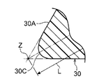
埋設部材30の中心Pから角部30Cの頂点Zまでの長さLは、ゴム突起14の高さHの30.3~39%の範囲内に設定されている。なお、図7Bに示すように、角部30Cの頂点Zは、埋設部材30の各辺の延長線の交点である。
なお、図7Aに示すように、本実施形態では、クローラ周方向断面で見てゴム突起14と埋設部材30が概ね相似形とされている。
次に、本実施形態のゴムクローラ10の作用効果について説明する。
ゴムクローラ10では、図7Aに示すように、駆動輪100の係合ピン101がゴム突起14の周方向ゴム壁面14Aに係合してゴム突起14に駆動力Fが入力される。ここで、クローラ周方向断面で見てゴム突起14に埋設された埋設部材30の周方向壁面30Aが周方向ゴム壁面14Aに沿っている、すなわち、周方向壁面30Aに対応する部分のゴム厚みが概ね等しくなっていることから、係合ピン101からの入力が埋設部材30の周方向壁面30Aによって広い範囲で受け止められる。これにより、ゴム突起14の埋設部材30周りに歪みが集中するのを抑制することができる。
ゴムクローラ10では、図7Aに示すように、駆動輪100の係合ピン101がゴム突起14の周方向ゴム壁面14Aに係合してゴム突起14に駆動力Fが入力される。ここで、クローラ周方向断面で見てゴム突起14に埋設された埋設部材30の周方向壁面30Aが周方向ゴム壁面14Aに沿っている、すなわち、周方向壁面30Aに対応する部分のゴム厚みが概ね等しくなっていることから、係合ピン101からの入力が埋設部材30の周方向壁面30Aによって広い範囲で受け止められる。これにより、ゴム突起14の埋設部材30周りに歪みが集中するのを抑制することができる。
また、埋設部材30が埋設されることでゴム突起14の曲げ剛性が向上するため、係合ピン101からの入力によってゴム突起14が倒れるように弾性変形するのが抑制される。
またさらに、ゴムクローラ10では、ゴム突起14の幅方向ゴム壁面14B、及び該幅方向ゴム壁面14Bから露出した埋設部材30の端部30Bに駆動輪100の側面部が当接することで、該駆動輪100とゴムベルト12とのクローラ幅方向の相対変位を制限することができる。
さらに、ゴム突起14よりも耐摩耗性が高い樹脂材料で埋設部材30を形成していることから、駆動輪100との摩擦によるゴム突起14の幅方向ゴム壁面14Bの摩耗を抑制することができる。
さらに、ゴム突起14よりも耐摩耗性が高い樹脂材料で埋設部材30を形成していることから、駆動輪100との摩擦によるゴム突起14の幅方向ゴム壁面14Bの摩耗を抑制することができる。
ゴムクローラ10では、埋設部材30の周方向壁面30Aを、クローラ厚み方向に対して傾斜する傾斜平面としていることから、例えば、周方向壁面を湾曲面としているものと比べて、係合ピン101からの入力を埋設部材30の周方向壁面30A全体で概ね均等に受けることができる。
また、埋設部材30のクローラ周方向断面で見た断面形状を、三角形状としていることから、例えば、台形状や、その他の多角形状としたものと比べて、埋設部材30を軽量化することができる。
またさらに、埋設部材30には角部30Cが複数個所形成されていることから、車輪との接触によって端部30Bが車輪の回転方向の力を受けても、角部30Cと周囲のゴムとの係合によって埋設部材30の動きが抑制される。これにより、ゴム突起14の埋設部材30周りに過剰な歪みが生じるのを抑制することができる。
また、埋設部材30の中心Pの高さH1をゴム突起14の高さH0の15.2~60.1%の範囲内に設定し、埋設部材30の中心Pから角部30Cの頂点Zまでの長さLをゴム突起14の高さHの30.3~39%の範囲内に設定することで、ゴム突起14の埋設部材30周りに歪みが集中するのを効果的に抑制することができる。
第1実施形態では、埋設部材30をクローラ幅方向に延びる三角柱状としているが、本発明はこの構成に限定されず、埋設部材30にクローラ幅方向に延びる中空部(例えば、貫通孔)などを形成してもよい。上記構成とすることで、埋設部材30を軽量化することができる。
第1実施形態では、本発明の無端状のゴム体(ゴム弾性を有する物体(すなわちゴム弾性体))の一例としてゴム材を無端帯状に形成したゴムベルト12を用いているが、本発明はこの構成に限定されず、ゴム弾性を有するエラストマ材を無端帯状に形成したエラストマベルトを用いてもよい。
以上、実施形態を挙げて本発明の実施の形態を説明したが、これらの実施形態は一例であり、要旨を逸脱しない範囲内で種々変更して実施できる。また、本発明の権利範囲がこれらの実施形態に限定されないことは言うまでもない。
(試験例)
本発明の効果を確かめるために、本発明に含まれる実施例のゴムクローラと、本発明に含まれない比較例のゴムクローラとを以下のように試験した。試験には、同じサイズの供試クローラを用いた。
本発明の効果を確かめるために、本発明に含まれる実施例のゴムクローラと、本発明に含まれない比較例のゴムクローラとを以下のように試験した。試験には、同じサイズの供試クローラを用いた。
<供試ゴムクローラ>
・実施例:第1実施形態のゴムクローラと同じ構造であり、ゴム突起14の高さH0を64mm、埋設部材30の中心Pの高さH1を38.5mm、埋設部材30の中心Pから頂点Zまでの長さLを19.4mmに設定したゴムクローラである。
・比較例:埋設部材30を円柱状とし、その他の構造を実施例のゴムクローラと同じ構造としたゴムクローラである。
・実施例:第1実施形態のゴムクローラと同じ構造であり、ゴム突起14の高さH0を64mm、埋設部材30の中心Pの高さH1を38.5mm、埋設部材30の中心Pから頂点Zまでの長さLを19.4mmに設定したゴムクローラである。
・比較例:埋設部材30を円柱状とし、その他の構造を実施例のゴムクローラと同じ構造としたゴムクローラである。
<試験1>
供試ゴムクローラのゴム突起14の周方向ゴム壁面14Aに駆動輪100の係合ピン101を所定の力で押し付けたときにゴム突起14に生じる歪みをFEM解析で求めた。結果を表1に示す。なお、表1の数値は、小さいほど良好な結果を示す。
供試ゴムクローラのゴム突起14の周方向ゴム壁面14Aに駆動輪100の係合ピン101を所定の力で押し付けたときにゴム突起14に生じる歪みをFEM解析で求めた。結果を表1に示す。なお、表1の数値は、小さいほど良好な結果を示す。

<試験2>
実施例のゴムクローラの埋設部材30のゴム突起14内での配置位置及び大きさ(断面積)をそれぞれ変化(高さH1及び長さLを変化)させたときのゴム突起14に生じる歪みの最大値をFEM解析で求めた。結果を表2に示す。なお、表2の数値は、小さいほど良好な結果を示す。
実施例のゴムクローラの埋設部材30のゴム突起14内での配置位置及び大きさ(断面積)をそれぞれ変化(高さH1及び長さLを変化)させたときのゴム突起14に生じる歪みの最大値をFEM解析で求めた。結果を表2に示す。なお、表2の数値は、小さいほど良好な結果を示す。

表1、表2から分かるように、本発明に含まれる実施例のゴムクローラは、比較例のゴムクローラと比べて、ゴム突起の埋設部材周りに歪みが集中するのが抑制されていることが分かる。
また、実施例のゴムクローラの高さH1、長さLを表2に示すように変化させた結果、いずれの歪み値も比較例の最大歪みよりも小さいことが分かる。従って、高さH1をゴム突起の高さH0の15.2~60.1%の範囲内に設定し、長さLをゴム突起の高さH0の30.3~39%の範囲内に設定することが好ましい。
また、実施例のゴムクローラの高さH1、長さLを表2に示すように変化させた結果、いずれの歪み値も比較例の最大歪みよりも小さいことが分かる。従って、高さH1をゴム突起の高さH0の15.2~60.1%の範囲内に設定し、長さLをゴム突起の高さH0の30.3~39%の範囲内に設定することが好ましい。
Claims (3)
- 駆動輪に巻き掛けられる無端帯状のゴム体と、
前記ゴム体に該ゴム体周方向に間隔をあけて複数設けられ、ゴム体内周側に突出し、ゴム体幅方向から見て頂部から根元部にかけて次第に幅広となる山形状とされ、ゴム体周方向のゴム壁面に前記駆動輪に設けられた係合ピンが係合して駆動力が入力されるゴム突起と、
前記ゴム突起に埋設され、ゴム体周方向に沿った断面で見てゴム体周方向の壁面が前記ゴム壁面に沿っている埋設部材と、
を有するゴムクローラ。 - 前記埋設部材のゴム体周方向の壁面は、ゴム体厚み方向に対して傾斜する傾斜平面である、請求項1に記載のゴムクローラ。
- 埋設部材は、ゴム体周方向に沿った断面で見て三角形状とされている、請求項2に記載のゴムクローラ。
Priority Applications (3)
| Application Number | Priority Date | Filing Date | Title |
|---|---|---|---|
| EP13816295.3A EP2873594B1 (en) | 2012-07-10 | 2013-06-18 | Rubber crawler |
| CN201380036077.8A CN104411572B (zh) | 2012-07-10 | 2013-06-18 | 橡胶履带 |
| US14/409,476 US9637187B2 (en) | 2012-07-10 | 2013-06-18 | Rubber crawler |
Applications Claiming Priority (2)
| Application Number | Priority Date | Filing Date | Title |
|---|---|---|---|
| JP2012-154906 | 2012-07-10 | ||
| JP2012154906A JP2014015156A (ja) | 2012-07-10 | 2012-07-10 | ゴムクローラ |
Publications (1)
| Publication Number | Publication Date |
|---|---|
| WO2014010378A1 true WO2014010378A1 (ja) | 2014-01-16 |
Family
ID=49915846
Family Applications (1)
| Application Number | Title | Priority Date | Filing Date |
|---|---|---|---|
| PCT/JP2013/066761 Ceased WO2014010378A1 (ja) | 2012-07-10 | 2013-06-18 | ゴムクローラ |
Country Status (5)
| Country | Link |
|---|---|
| US (1) | US9637187B2 (ja) |
| EP (1) | EP2873594B1 (ja) |
| JP (1) | JP2014015156A (ja) |
| CN (1) | CN104411572B (ja) |
| WO (1) | WO2014010378A1 (ja) |
Families Citing this family (16)
| Publication number | Priority date | Publication date | Assignee | Title |
|---|---|---|---|---|
| US20160016621A1 (en) | 2013-03-15 | 2016-01-21 | Camoplast Solideal Inc. | Endless track for traction of a vehicle |
| JP6053174B2 (ja) * | 2013-11-07 | 2016-12-27 | 株式会社クボタ | ゴムクローラ |
| EP3265368B2 (en) | 2015-03-04 | 2024-07-24 | Camso Inc. | Track system for traction of a vehicle |
| JP6473373B2 (ja) | 2015-04-16 | 2019-02-20 | 株式会社ブリヂストン | 弾性クローラおよび弾性クローラ駆動機構 |
| US10875591B2 (en) * | 2015-08-04 | 2020-12-29 | Camso Inc. | Track system for traction of an agricultural vehicle travelling on fields and roads |
| CA2953991A1 (en) * | 2016-01-07 | 2017-07-07 | Camso Inc. | Track system for traction of a vehicle |
| EP3449712B1 (en) | 2016-04-27 | 2024-06-05 | Positec Power Tools (Suzhou) Co., Ltd | Smart crawler belt moving device |
| CN106672099A (zh) * | 2016-12-15 | 2017-05-17 | 青岛开世橡胶履带有限公司 | 一种高速橡胶履带及其制备方法 |
| CA3051070A1 (en) * | 2017-01-20 | 2018-07-26 | Bridgestone Corporation | Rubber crawler, rubber crawler mold, and method of producing rubber crawler |
| JP6758206B2 (ja) * | 2017-01-20 | 2020-09-23 | 株式会社ブリヂストン | ゴムクローラ |
| CN107640239A (zh) * | 2017-09-22 | 2018-01-30 | 镇江市胜得机械制造有限责任公司 | 一种挖掘机橡胶履带 |
| CN107600207A (zh) * | 2017-10-25 | 2018-01-19 | 镇江市胜得机械制造有限责任公司 | 一种橡胶履带加强块 |
| JPWO2020080448A1 (ja) * | 2018-10-16 | 2021-09-02 | 株式会社ブリヂストン | 弾性クローラ |
| US11572115B2 (en) * | 2019-07-17 | 2023-02-07 | Srj, Inc. | Tread pattern |
| JP7508981B2 (ja) * | 2020-10-02 | 2024-07-02 | 住友ゴム工業株式会社 | 弾性クローラ |
| WO2025086011A1 (en) * | 2023-10-25 | 2025-05-01 | Soucy International Inc. | Endless track for a track system and track system having same |
Citations (7)
| Publication number | Priority date | Publication date | Assignee | Title |
|---|---|---|---|---|
| JP2000033889A (ja) | 1998-07-16 | 2000-02-02 | Bridgestone Corp | ゴムクロ−ラ |
| WO2000055032A1 (en) * | 1999-03-17 | 2000-09-21 | Edwards John W | Endless drive track with improved drive lug configuration and reinforcing brace and method |
| JP2002211455A (ja) * | 2001-01-19 | 2002-07-31 | Ohtsu Tire & Rubber Co Ltd :The | 弾性クローラ |
| JP2004330830A (ja) * | 2003-05-02 | 2004-11-25 | Sumitomo Rubber Ind Ltd | 弾性クローラ |
| JP2006062589A (ja) * | 2004-08-30 | 2006-03-09 | Sumitomo Rubber Ind Ltd | 弾性クローラ |
| JP2006088664A (ja) * | 2004-09-27 | 2006-04-06 | Bridgestone Corp | ゴムクロ−ラの製法 |
| JP2007022304A (ja) * | 2005-07-15 | 2007-02-01 | Bridgestone Corp | クローラの駆動突起構造 |
Family Cites Families (17)
| Publication number | Priority date | Publication date | Assignee | Title |
|---|---|---|---|---|
| US3747995A (en) * | 1971-07-12 | 1973-07-24 | Gates Rubber Co | Reinforcement for endless track |
| US3858948A (en) * | 1973-04-30 | 1975-01-07 | Goodyear Tire & Rubber | Belt track for vehicles |
| US6079802A (en) * | 1997-07-23 | 2000-06-27 | Bridgestone Corporation | Rubber crawler |
| US6196646B1 (en) * | 1999-03-17 | 2001-03-06 | John W. Edwards | Endless drive track system with reinforcing brace and method |
| JP3805974B2 (ja) * | 2000-12-01 | 2006-08-09 | 住友ゴム工業株式会社 | 弾性クローラ |
| JP2003034275A (ja) * | 2001-07-23 | 2003-02-04 | Komatsu Ltd | 弾性履帯 |
| US6793296B2 (en) * | 2002-10-09 | 2004-09-21 | Soucy International Inc. | Endless traction band with asymmetrical support |
| JP2004322866A (ja) * | 2003-04-25 | 2004-11-18 | Bridgestone Corp | ゴムクロ−ラ |
| US7784884B2 (en) * | 2004-03-03 | 2010-08-31 | Soucy International Inc. | Elastomeric track with guide lug reinforcements |
| JP4042858B2 (ja) * | 2004-03-09 | 2008-02-06 | 住友ゴム工業株式会社 | 弾性クローラ |
| JP2006321387A (ja) * | 2005-05-19 | 2006-11-30 | Bridgestone Corp | 芯金レスクロ−ラの走行装置 |
| JP4949721B2 (ja) * | 2006-04-11 | 2012-06-13 | 株式会社ブリヂストン | 芯金レスクローラ |
| US7740326B2 (en) | 2005-05-19 | 2010-06-22 | Bridgestone Corporation | Core-less crawler track and rubber projections therefore |
| EP2055616B1 (en) * | 2006-08-25 | 2013-11-20 | Bridgestone Corporation | Rubber track |
| CN201049657Y (zh) * | 2007-04-29 | 2008-04-23 | 林祥雄 | 一种橡胶履带 |
| CN102481957B (zh) * | 2009-10-13 | 2014-12-24 | 株式会社久保田 | 履带式行进装置 |
| CN103118930B (zh) * | 2010-09-21 | 2015-09-30 | 株式会社普利司通 | 弹性履带 |
-
2012
- 2012-07-10 JP JP2012154906A patent/JP2014015156A/ja active Pending
-
2013
- 2013-06-18 US US14/409,476 patent/US9637187B2/en not_active Expired - Fee Related
- 2013-06-18 WO PCT/JP2013/066761 patent/WO2014010378A1/ja not_active Ceased
- 2013-06-18 CN CN201380036077.8A patent/CN104411572B/zh not_active Expired - Fee Related
- 2013-06-18 EP EP13816295.3A patent/EP2873594B1/en not_active Not-in-force
Patent Citations (7)
| Publication number | Priority date | Publication date | Assignee | Title |
|---|---|---|---|---|
| JP2000033889A (ja) | 1998-07-16 | 2000-02-02 | Bridgestone Corp | ゴムクロ−ラ |
| WO2000055032A1 (en) * | 1999-03-17 | 2000-09-21 | Edwards John W | Endless drive track with improved drive lug configuration and reinforcing brace and method |
| JP2002211455A (ja) * | 2001-01-19 | 2002-07-31 | Ohtsu Tire & Rubber Co Ltd :The | 弾性クローラ |
| JP2004330830A (ja) * | 2003-05-02 | 2004-11-25 | Sumitomo Rubber Ind Ltd | 弾性クローラ |
| JP2006062589A (ja) * | 2004-08-30 | 2006-03-09 | Sumitomo Rubber Ind Ltd | 弾性クローラ |
| JP2006088664A (ja) * | 2004-09-27 | 2006-04-06 | Bridgestone Corp | ゴムクロ−ラの製法 |
| JP2007022304A (ja) * | 2005-07-15 | 2007-02-01 | Bridgestone Corp | クローラの駆動突起構造 |
Also Published As
| Publication number | Publication date |
|---|---|
| US9637187B2 (en) | 2017-05-02 |
| CN104411572A (zh) | 2015-03-11 |
| EP2873594B1 (en) | 2018-10-10 |
| JP2014015156A (ja) | 2014-01-30 |
| CN104411572B (zh) | 2017-10-10 |
| EP2873594A4 (en) | 2016-03-09 |
| EP2873594A1 (en) | 2015-05-20 |
| US20150321712A1 (en) | 2015-11-12 |
Similar Documents
| Publication | Publication Date | Title |
|---|---|---|
| JP2014015156A (ja) | ゴムクローラ | |
| CN103492258B (zh) | 履带行进装置和弹性履带 | |
| US10730571B2 (en) | Crawler | |
| JP5851344B2 (ja) | ゴムクローラ | |
| JP2009029206A (ja) | ゴムクローラ | |
| JP5985261B2 (ja) | 弾性クローラ | |
| US9446806B2 (en) | Rubber crawler | |
| US10053169B2 (en) | Crawler | |
| US10618578B2 (en) | Crawler | |
| JP2012096638A (ja) | 弾性クローラ | |
| JP2013107472A (ja) | 弾性クローラ | |
| JP5808633B2 (ja) | 弾性クローラ及びクローラ走行装置 | |
| JP5770560B2 (ja) | 弾性クローラ及びクローラ走行装置 | |
| JP5602268B2 (ja) | 弾性クローラ | |
| JP6574116B2 (ja) | 芯金レスクローラ及び芯金レスクローラ装置 | |
| JP5901375B2 (ja) | ゴムクローラ | |
| JP2016107990A (ja) | クローラ | |
| JP2015202786A (ja) | クローラ |
Legal Events
| Date | Code | Title | Description |
|---|---|---|---|
| 121 | Ep: the epo has been informed by wipo that ep was designated in this application |
Ref document number: 13816295 Country of ref document: EP Kind code of ref document: A1 |
|
| WWE | Wipo information: entry into national phase |
Ref document number: 14409476 Country of ref document: US |
|
| NENP | Non-entry into the national phase |
Ref country code: DE |
|
| WWE | Wipo information: entry into national phase |
Ref document number: 2013816295 Country of ref document: EP |