WO2014010423A1 - 消火装置 - Google Patents
消火装置 Download PDFInfo
- Publication number
- WO2014010423A1 WO2014010423A1 PCT/JP2013/067533 JP2013067533W WO2014010423A1 WO 2014010423 A1 WO2014010423 A1 WO 2014010423A1 JP 2013067533 W JP2013067533 W JP 2013067533W WO 2014010423 A1 WO2014010423 A1 WO 2014010423A1
- Authority
- WO
- WIPO (PCT)
- Prior art keywords
- sand
- fire extinguishing
- nitrogen gas
- fire
- container
- Prior art date
- Legal status (The legal status is an assumption and is not a legal conclusion. Google has not performed a legal analysis and makes no representation as to the accuracy of the status listed.)
- Ceased
Links
Images



Classifications
-
- A—HUMAN NECESSITIES
- A62—LIFE-SAVING; FIRE-FIGHTING
- A62C—FIRE-FIGHTING
- A62C13/00—Portable extinguishers which are permanently pressurised or pressurised immediately before use
- A62C13/66—Portable extinguishers which are permanently pressurised or pressurised immediately before use with extinguishing material and pressure gas being stored in separate containers
- A62C13/68—Portable extinguishers which are permanently pressurised or pressurised immediately before use with extinguishing material and pressure gas being stored in separate containers characterised by means for releasing the extinguishing material
-
- A—HUMAN NECESSITIES
- A62—LIFE-SAVING; FIRE-FIGHTING
- A62C—FIRE-FIGHTING
- A62C13/00—Portable extinguishers which are permanently pressurised or pressurised immediately before use
- A62C13/66—Portable extinguishers which are permanently pressurised or pressurised immediately before use with extinguishing material and pressure gas being stored in separate containers
- A62C13/70—Portable extinguishers which are permanently pressurised or pressurised immediately before use with extinguishing material and pressure gas being stored in separate containers characterised by means for releasing the pressure gas
-
- A—HUMAN NECESSITIES
- A62—LIFE-SAVING; FIRE-FIGHTING
- A62C—FIRE-FIGHTING
- A62C13/00—Portable extinguishers which are permanently pressurised or pressurised immediately before use
- A62C13/006—Portable extinguishers which are permanently pressurised or pressurised immediately before use for the propulsion of extinguishing powder
-
- A—HUMAN NECESSITIES
- A62—LIFE-SAVING; FIRE-FIGHTING
- A62C—FIRE-FIGHTING
- A62C13/00—Portable extinguishers which are permanently pressurised or pressurised immediately before use
- A62C13/66—Portable extinguishers which are permanently pressurised or pressurised immediately before use with extinguishing material and pressure gas being stored in separate containers
- A62C13/72—Portable extinguishers which are permanently pressurised or pressurised immediately before use with extinguishing material and pressure gas being stored in separate containers characterised by releasing means operating essentially simultaneously on both containers
-
- A—HUMAN NECESSITIES
- A62—LIFE-SAVING; FIRE-FIGHTING
- A62C—FIRE-FIGHTING
- A62C99/00—Subject matter not provided for in other groups of this subclass
- A62C99/0009—Methods of extinguishing or preventing the spread of fire by cooling down or suffocating the flames
- A62C99/0045—Methods of extinguishing or preventing the spread of fire by cooling down or suffocating the flames using solid substances, e.g. sand, ashes; using substances forming a crust
-
- A—HUMAN NECESSITIES
- A62—LIFE-SAVING; FIRE-FIGHTING
- A62C—FIRE-FIGHTING
- A62C3/00—Fire prevention, containment or extinguishing specially adapted for particular objects or places
- A62C3/06—Fire prevention, containment or extinguishing specially adapted for particular objects or places of highly inflammable material, e.g. light metals, petroleum products
-
- A—HUMAN NECESSITIES
- A62—LIFE-SAVING; FIRE-FIGHTING
- A62C—FIRE-FIGHTING
- A62C3/00—Fire prevention, containment or extinguishing specially adapted for particular objects or places
- A62C3/16—Fire prevention, containment or extinguishing specially adapted for particular objects or places in electrical installations, e.g. cableways
Definitions
- the present invention relates to a fire extinguishing apparatus suitable for extinguishing a fire extinguishing object such as a high-temperature operation type battery.
- a charging system using a sodium-sulfur battery is configured by combining a large number of battery modules in which several hundred cells are housed in a heat insulating container. In the unlikely event that such a battery module ignites, a hot sodium and sulfur melt may spurt out to the ceiling surface of the insulated container, causing a violent oxidation reaction when in contact with air, and the fire may spread. . Since there is sodium, fire extinguishing with water is impossible, so suffocation extinguishing with air using fire extinguishing sand is necessary. When the charging system using the sodium-sulfur battery has a structure in which a plurality of battery modules are stacked, the height may reach several meters. For this reason, the fire extinguishing apparatus is required to have the ability to lift fire sand up to a height of several meters and inject it.
- Patent Document 1 of the present applicant describes a fire extinguishing device for spraying ceramic particles toward a fire extinguishing target.
- This apparatus has a structure in which ceramic particles are stored in a storage tank, and ceramic particles are sent out from the bottom of the storage tank using a gas pressure applied to the storage tank from a gas cylinder.
- an object of the present invention is to provide a fire extinguishing apparatus that solves the above-described conventional problems, is low in production cost, is easy to handle, and can replenish fire storage sand in a storage tank during a fire fighting operation. is there.
- the fire extinguishing apparatus of the present invention made to solve the above problems includes a sand container storing fire extinguishing sand, a nitrogen gas cylinder, and an ejector to which nitrogen gas extracted from the nitrogen gas cylinder through a pressure reducing valve is supplied.
- the ejector is connected to a suction pipe for sucking fire extinguishing sand from the sand container using a negative pressure generated by a nitrogen gas flow, and a delivery pipe for sending the sucked fire extinguishing sand together with nitrogen gas.
- the sand container cover plate is formed with an openable and closable sand inlet.
- the suction pipe in the position remove
- the fire extinguishing sand is an expanded meteorite, and as in claim 5, it is preferable that the sand container, the nitrogen gas cylinder, and the ejector are mounted on the movable carriage. preferable.
- the fire extinguisher of the present invention generates a negative pressure by a nitrogen gas flow in the ejector, sucks the fire extinguishing sand from the sand container using this negative pressure, and sends it out together with the nitrogen gas. For this reason, it is not necessary to make a sand container into a pressurized container, and manufacture and handling are easy. Moreover, since fire-extinguishing sand can be replenished at any time during the fire-extinguishing work, sand shortage does not occur during the fire-extinguishing work.
- the suction pipe is arranged at a position off the center of the sand container as in claim 2, the fire sand is less likely to cause a blocking phenomenon inside the sand container, and the fire sand can be sent out continuously. it can.
- the structure is further provided with a nitrogen-filled tube for further reducing the pressure of the nitrogen gas taken out from the nitrogen gas cylinder through the pressure reducing valve and introducing the same into the sand container, it is stored inside the sand container.
- the fire extinguishing sand is no longer in contact with air and does not absorb moisture or change its quality.
- a structure in which a sand container, a nitrogen gas cylinder, and an ejector are mounted on a moving carriage can be easily moved in the event of a fire. Moreover, since no power supply is required, fire fighting can be started immediately.
- FIG. 1 is a front view of a fire extinguisher according to the embodiment
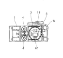
- FIG. 2 is a plan view thereof
- FIG. 3 is a piping system diagram.
- reference numeral 1 denotes a moving carriage provided with traveling wheels 2 on which a sand container 3, a nitrogen gas cylinder 4, and an ejector 5 are mounted.
- the sand container 3 is a drum, and an expanded meteorite, which is fire extinguishing sand, is accommodated therein.
- the capacity of a general drum can is 200 liters, but in order to avoid the blocking phenomenon inside, it is preferable to keep the filling amount of the expanded meteorite smaller.
- Expanded meteorite (vermiculite) has a small bulk specific gravity and has the property of expanding when heated and forming an air barrier layer. According to experiments, a sufficient fire-extinguishing effect can be obtained if the meteorite is deposited to about 3 cm.
- the particle size of the fire extinguishing sand is preferably about 3 to 5 mm.
- fire extinguishing sand is not necessarily limited to expanded meteorites.
- two nitrogen gas cylinders 4 are mounted. This is to avoid the danger that the gas pressure drops during fire extinguishing work and cannot be extinguished, and one is a spare cylinder.
- the nitrogen gas cylinder 4 a commercially available product having a capacity of 47 liters and a primary pressure of 14.7 MPa can be used. These nitrogen gas cylinders 4 are connected to the pressure reducing valve 6 shown in FIG. 3, and the nitrogen gas is decompressed to about 0.3 MPa and then supplied to the ejector 5.
- the ejector 5 generates a negative pressure by the supplied nitrogen gas flow. For this reason, if the suction pipe 7 is connected to the base of the ejector 5 and its tip is inserted deeply into the sand container 3, the fire-extinguishing sand can be sucked from the sand container 3.
- a delivery pipe 8 is connected to the tip of the ejector 5, and the sucked fire extinguishing sand is sent to the delivery pipe 8 along with the nitrogen gas flow.
- a metal pipe 9 and a nozzle 10 are connected to the tip of the delivery pipe 8, and fire extinguishing sand can be ejected from the tip of the nozzle 10 together with nitrogen gas.
- the flow rate of the nitrogen gas supplied to the ejector 5 is preferably 700 liters per minute or more.
- the suction pipe 7 is preferably arranged at a position deviated to one side from the center of the sand container 3. If the suction pipe 7 is in the center of the sand container 3, blocking is likely to occur because the fire extinguishing sand is sucked evenly from the surroundings. However, if the suction pipe 7 is in the eccentric position, the balance is lost and blocking is difficult to occur. It becomes possible to send out fire-extinguishing sand.
- a sand inlet 12 as shown in FIG. 2 is formed in the cover plate 11 of the sand container 3.
- the lid plate 11 and the sand inlet 12 are both airtight lids provided with packing, but can be opened as necessary. For this reason, the sand inlet 12 can be opened during the fire extinguishing work to replenish the fire extinguishing sand, and there is no shortage of sand during the fire extinguishing work.
- the conventional pressure vessel type fire extinguisher such replenishment is impossible during a fire extinguishing operation, but in the suction type fire extinguisher of the present invention, replenishment is possible, which is a great advantage of the fire extinguisher of the present invention. ing.
- fire extinguishing sand represented by expanded meteorite tends to harden due to humidity in the atmosphere, and if the dispersibility decreases due to moisture absorption, there is a risk that it will be difficult to be sucked smoothly into the suction pipe 7.
- This type of fire extinguishing device is usually not used for a long period of time, and if the fire extinguishing sand is hardened when a fire breaks out, it is not worthy as a fire extinguishing device. Therefore, as shown in FIG. 3, the outlet side of the pressure reducing valve 6 is branched, and the pressure regulating valve 13 reduces the pressure to a pressure slightly higher than the atmospheric pressure, and nitrogen gas is introduced into the sand container 3 through the nitrogen sealing tube 14.
- the inside of the sand container 3 is filled with nitrogen gas, and it is possible to reliably prevent trouble that the fire-extinguishing sand is hardened or deteriorated.
- a relief valve 15 is attached to the cover plate 11 of the sand container 3, and when the internal pressure rises abnormally, nitrogen gas is released to the outside to avoid the risk of destruction.
- FIG. 4 shows a state in which the fire extinguishing apparatus of the present invention is used for extinguishing a charging system using a sodium sulfur battery.
- the sodium-sulfur battery charging system is configured by combining a large number of battery modules 20 in accordance with the charging capacity.
- Each of these battery modules 20 is a rectangular parallelepiped having a width and a depth of about 1.5 m and a height of about 0.8 m, and is housed in multiple stages in a rack 21 having an overall height close to 5 m.
- a flat upper space 23 having a height of only about 5 cm is formed between the floor plate 22 of the rack 21 and the ceiling surface of the battery module 20.
- a door 24 is disposed on the front surface of the rack 21, and a horizontally long opening 25 is formed at a position corresponding to each upper space 23.
- an appropriate number of metal pipes 9 are connected to the tip of the delivery pipe 8 according to the height of the ignition source, and the nozzle 10 attached to the tip of the metal pipe 9 is inserted from the opening 25 of the door 24, Fire extinguishing sand is radiated into the upper space 23.
- the nozzle 10 is provided with a guide plate 27 having a positioning recess 26 on the lower surface thereof. If the nozzle 10 is inserted into the opening 25 and then pushed into the back as it is, a positioning plate as shown in FIG. The nozzle 10 can be positioned at a position where the recess 26 engages with the lower edge of the opening 25. Therefore, even when the ignition source is at a high place, a reliable fire extinguishing work can be performed.
- the metal pipes 9 can be used by sequentially adding an appropriate number according to the height of the ignition source. For this reason, it is preferable to mount several metal pipes 9 on the movable carriage 1 so that they can be used immediately.
- the fire extinguishing apparatus configured in this manner is moved to the vicinity of the ignition source in the event of a fire and the valve of the nitrogen gas cylinder 4 is opened, the ejector 5 generates a negative pressure due to the nitrogen gas flow, and the fire sand from the sand container 3 is generated. Aspirate.
- the sucked fire extinguishing sand is sent to the delivery pipe 8 along with the nitrogen gas flow, and can be ejected together with the nitrogen gas from the tip of the nozzle 10.
- Fire extinguishing sand covers the surface of the fire extinguishing object, blocks air and can extinguish the fire.
- the sand inlet 12 can be opened and the fire-extinguishing sand can be replenished during the fire-extinguishing work, there is no shortage of sand during the fire-extinguishing work.
- the fire extinguishing apparatus of the present invention does not require the use of a pressure vessel as the sand vessel 3, the production cost is low and the handling is easy.
- the fire extinguishing apparatus of the present invention is suitable for extinguishing a charging system using a sodium-sulfur battery, but needless to say, it can be used for other general fires.
Landscapes
- Health & Medical Sciences (AREA)
- Public Health (AREA)
- Business, Economics & Management (AREA)
- Emergency Management (AREA)
- Fire-Extinguishing By Fire Departments, And Fire-Extinguishing Equipment And Control Thereof (AREA)
- Secondary Cells (AREA)
Description
図1は実施形態の消火装置の正面図、図2はその平面図、図3は配管系統図である。図1、図2において1は走行車輪2を備えた移動台車であり、その上に砂容器3と、窒素ガスボンベ4と、エジェクタ5とが搭載されている。
2 走行車輪
3 砂容器
4 窒素ガスボンベ
5 エジェクタ
6 減圧弁
7 吸引管
8 送出管
9 パイプ
10 ノズル
11 蓋板
12 砂投入口
13 圧力調整弁
14 窒素封入管
15 リリーフ弁
20 電池モジュール
21 ラック
22 床板
23 上部空間
24 扉
25 開口
26 位置決め用凹部
27 ガイド板
Claims (5)
- 消火砂が収納された砂容器と、窒素ガスボンベと、この窒素ガスボンベから減圧弁を介して取り出された窒素ガスが供給されるエジェクタとからなり、
該エジェクタには窒素ガス流により発生する負圧を利用して砂容器内から消火砂を吸引する吸引管と、吸引された消火砂を窒素ガスとともに送出する送出管とが接続され、
砂容器の蓋板には開閉可能な砂投入口を形成したことを特徴とする消火装置。 - 吸引管を砂容器の中心から外れた位置に配置したことを特徴とする請求項1記載の消火装置。
- 窒素ガスボンベから減圧弁を介して取り出された窒素ガスをさらに減圧し、砂容器の内部に導入する窒素封入管を備えたことを特徴とする請求項1記載の消火装置。
- 消火砂が膨張蛭石であることを特徴とする請求項1記載の消火装置。
- 砂容器と、窒素ガスボンベと、エジェクタとを移動台車上に搭載したことを特徴とする請求項1記載の消火装置。
Priority Applications (4)
| Application Number | Priority Date | Filing Date | Title |
|---|---|---|---|
| CN201380028977.8A CN104334235B (zh) | 2012-07-13 | 2013-06-26 | 灭火装置 |
| EP13816905.7A EP2873441B1 (en) | 2012-07-13 | 2013-06-26 | Fire extinguisher |
| JP2014524729A JPWO2014010423A1 (ja) | 2012-07-13 | 2013-06-26 | 消火装置 |
| US14/561,343 US9522291B2 (en) | 2012-07-13 | 2014-12-05 | Fire extinguishing apparatus |
Applications Claiming Priority (2)
| Application Number | Priority Date | Filing Date | Title |
|---|---|---|---|
| JP2012-157257 | 2012-07-13 | ||
| JP2012157257 | 2012-07-13 |
Related Child Applications (1)
| Application Number | Title | Priority Date | Filing Date |
|---|---|---|---|
| US14/561,343 Continuation US9522291B2 (en) | 2012-07-13 | 2014-12-05 | Fire extinguishing apparatus |
Publications (1)
| Publication Number | Publication Date |
|---|---|
| WO2014010423A1 true WO2014010423A1 (ja) | 2014-01-16 |
Family
ID=49915887
Family Applications (1)
| Application Number | Title | Priority Date | Filing Date |
|---|---|---|---|
| PCT/JP2013/067533 Ceased WO2014010423A1 (ja) | 2012-07-13 | 2013-06-26 | 消火装置 |
Country Status (5)
| Country | Link |
|---|---|
| US (1) | US9522291B2 (ja) |
| EP (1) | EP2873441B1 (ja) |
| JP (1) | JPWO2014010423A1 (ja) |
| CN (1) | CN104334235B (ja) |
| WO (1) | WO2014010423A1 (ja) |
Cited By (5)
| Publication number | Priority date | Publication date | Assignee | Title |
|---|---|---|---|---|
| CN104027923A (zh) * | 2014-07-04 | 2014-09-10 | 安庆市鸿裕工业产品设计有限公司 | 一种黄沙粉末灭火装置 |
| WO2017216851A1 (ja) * | 2016-06-13 | 2017-12-21 | 株式会社コーアツ | 消火器 |
| CN107583220A (zh) * | 2017-10-26 | 2018-01-16 | 苏州深安注册安全工程师事务所有限公司 | 一种分体式多口自动装沙的消防设施放置箱 |
| CN111672041A (zh) * | 2020-06-19 | 2020-09-18 | 哈尔滨市三棵中药材市场太清参茸行 | 一种电线着火喷砂灭火装置 |
| KR20210061891A (ko) * | 2019-11-20 | 2021-05-28 | 이종관 | 금속화재 소화장치 |
Families Citing this family (10)
| Publication number | Priority date | Publication date | Assignee | Title |
|---|---|---|---|---|
| CN105148433A (zh) * | 2015-10-14 | 2015-12-16 | 何勇志 | 喷沙灭火装置 |
| DE102016206851B3 (de) | 2016-04-22 | 2017-10-26 | Audi Ag | Löschverfahren und Löscheinrichtung zum Einbringen wenigstens eines Löschmittels in eine Batterie |
| CN105833449A (zh) * | 2016-04-29 | 2016-08-10 | 羊丁 | 一种高速气体的自动喷砂消防机器人 |
| CN106823204B (zh) * | 2017-02-15 | 2022-04-22 | 应急管理部天津消防研究所 | 一种采用砂子正压喷射灭火系统及实现方法 |
| US20190290950A1 (en) * | 2018-03-26 | 2019-09-26 | Kidde Technologies, Inc. | Vermiculite based fire suppression agent |
| TWI666848B (zh) * | 2018-09-12 | 2019-07-21 | 財團法人工業技術研究院 | 蓄電系統消防裝置及其運作方法 |
| CN110624188A (zh) * | 2019-09-27 | 2019-12-31 | 东莞宜安科技股份有限公司 | 快速灭火装置 |
| CN111346331B (zh) * | 2020-03-17 | 2021-04-23 | 全恒国际创意(深圳)有限公司 | 一种室内火灾自动处理装置 |
| CN112023303B (zh) * | 2020-09-10 | 2021-05-11 | 宁德师范学院 | 一种适用于电气设备的自动灭火装置 |
| CN114807537A (zh) * | 2022-02-26 | 2022-07-29 | 苏州民生电热工程有限公司 | 一种淬火油槽的灭火和烟气收集机构 |
Citations (7)
| Publication number | Priority date | Publication date | Assignee | Title |
|---|---|---|---|---|
| JPH03100222U (ja) * | 1990-01-30 | 1991-10-21 | ||
| SU822686A1 (ru) * | 1980-01-10 | 1991-11-07 | Предприятие П/Я В-2679 | Способ подготовки вермикулита дл пожаротушени натри |
| JPH06269509A (ja) | 1993-03-17 | 1994-09-27 | Ngk Insulators Ltd | 消火剤の散布器 |
| JPH07165333A (ja) * | 1993-10-22 | 1995-06-27 | Showa Tansan Kk | 粉粒体の供給装置 |
| JPH09653A (ja) * | 1995-06-23 | 1997-01-07 | Hitachi Ltd | ナトリウム火炎の消火方法 |
| JPH09154971A (ja) * | 1995-12-01 | 1997-06-17 | Hatsuta Seisakusho:Kk | 消火器 |
| JP2006025806A (ja) * | 2004-07-12 | 2006-02-02 | Ashimori Ind Co Ltd | 消火装置 |
Family Cites Families (12)
| Publication number | Priority date | Publication date | Assignee | Title |
|---|---|---|---|---|
| GB254195A (en) * | 1925-12-22 | 1926-07-01 | Kornel Szilvay | Improvements relating to the method of and apparatus for extinguishing fire |
| US1839658A (en) * | 1929-10-30 | 1932-01-05 | Gas Fire Extinguisher Corp Du | Method of extinguishing fires |
| JPS52137200A (en) * | 1976-05-10 | 1977-11-16 | Japan Synthetic Rubber Co Ltd | Fire extinguishing method and device |
| FR2371207A1 (fr) * | 1976-11-22 | 1978-06-16 | Ceca Sa | Procede d'extinction des feux de metaux, et produit a cet effet |
| JPH04300564A (ja) * | 1991-03-28 | 1992-10-23 | Ngk Insulators Ltd | 消火剤及び消火装置 |
| JP2703430B2 (ja) * | 1991-09-26 | 1998-01-26 | 日本碍子株式会社 | ナトリウム−硫黄電池における消火装置 |
| JP2703431B2 (ja) * | 1991-09-26 | 1998-01-26 | 日本碍子株式会社 | ナトリウム−硫黄電池における消火装置 |
| US5810089A (en) * | 1996-04-19 | 1998-09-22 | Task Force Tips, Inc. | Portable firefighting apparatus with integral control valve-handle |
| JP3100222U (ja) | 2003-09-03 | 2004-05-13 | 株式会社安眠 | 枕 |
| DE102006019739B4 (de) * | 2006-04-28 | 2008-07-10 | Patentverwertung GbR (vertretungsberchtigte Gesellschafter: Bärbel Knopf, Fischersteeg 11 | System zum Löschen von Bränden und Verfahren zu dessen Einsatz |
| CN2936308Y (zh) * | 2006-05-31 | 2007-08-22 | 天津市三源电力设备制造有限公司 | 移动式消防砂箱 |
| CN201537338U (zh) * | 2009-12-01 | 2010-08-04 | 蒋夫志 | 消防用灭火沙车 |
-
2013
- 2013-06-26 CN CN201380028977.8A patent/CN104334235B/zh active Active
- 2013-06-26 WO PCT/JP2013/067533 patent/WO2014010423A1/ja not_active Ceased
- 2013-06-26 EP EP13816905.7A patent/EP2873441B1/en active Active
- 2013-06-26 JP JP2014524729A patent/JPWO2014010423A1/ja active Pending
-
2014
- 2014-12-05 US US14/561,343 patent/US9522291B2/en active Active
Patent Citations (7)
| Publication number | Priority date | Publication date | Assignee | Title |
|---|---|---|---|---|
| SU822686A1 (ru) * | 1980-01-10 | 1991-11-07 | Предприятие П/Я В-2679 | Способ подготовки вермикулита дл пожаротушени натри |
| JPH03100222U (ja) * | 1990-01-30 | 1991-10-21 | ||
| JPH06269509A (ja) | 1993-03-17 | 1994-09-27 | Ngk Insulators Ltd | 消火剤の散布器 |
| JPH07165333A (ja) * | 1993-10-22 | 1995-06-27 | Showa Tansan Kk | 粉粒体の供給装置 |
| JPH09653A (ja) * | 1995-06-23 | 1997-01-07 | Hitachi Ltd | ナトリウム火炎の消火方法 |
| JPH09154971A (ja) * | 1995-12-01 | 1997-06-17 | Hatsuta Seisakusho:Kk | 消火器 |
| JP2006025806A (ja) * | 2004-07-12 | 2006-02-02 | Ashimori Ind Co Ltd | 消火装置 |
Non-Patent Citations (1)
| Title |
|---|
| See also references of EP2873441A4 * |
Cited By (8)
| Publication number | Priority date | Publication date | Assignee | Title |
|---|---|---|---|---|
| CN104027923A (zh) * | 2014-07-04 | 2014-09-10 | 安庆市鸿裕工业产品设计有限公司 | 一种黄沙粉末灭火装置 |
| WO2017216851A1 (ja) * | 2016-06-13 | 2017-12-21 | 株式会社コーアツ | 消火器 |
| CN109310898A (zh) * | 2016-06-13 | 2019-02-05 | 株式会社高压 | 灭火器 |
| RU2717772C1 (ru) * | 2016-06-13 | 2020-03-25 | Коацу Ко., Лтд. | Огнетушитель |
| CN107583220A (zh) * | 2017-10-26 | 2018-01-16 | 苏州深安注册安全工程师事务所有限公司 | 一种分体式多口自动装沙的消防设施放置箱 |
| KR20210061891A (ko) * | 2019-11-20 | 2021-05-28 | 이종관 | 금속화재 소화장치 |
| KR102343812B1 (ko) * | 2019-11-20 | 2021-12-27 | 이종관 | 금속화재 소화장치 |
| CN111672041A (zh) * | 2020-06-19 | 2020-09-18 | 哈尔滨市三棵中药材市场太清参茸行 | 一种电线着火喷砂灭火装置 |
Also Published As
| Publication number | Publication date |
|---|---|
| JPWO2014010423A1 (ja) | 2016-06-23 |
| CN104334235B (zh) | 2016-12-14 |
| EP2873441A4 (en) | 2015-12-09 |
| US20150083446A1 (en) | 2015-03-26 |
| EP2873441A1 (en) | 2015-05-20 |
| US9522291B2 (en) | 2016-12-20 |
| EP2873441B1 (en) | 2018-03-14 |
| CN104334235A (zh) | 2015-02-04 |
Similar Documents
| Publication | Publication Date | Title |
|---|---|---|
| WO2014010423A1 (ja) | 消火装置 | |
| KR20170039144A (ko) | 갈바닉 셀을 운반하는 장치 및 방법 | |
| CN210904737U (zh) | 一种加油站消防灭火装置 | |
| CN107658512A (zh) | 一种灌液式消防的电池模组仓储与充放电箱体系统 | |
| US11975461B2 (en) | Inertable container for transporting an additive manufacturing powder | |
| US20170110757A1 (en) | Apparatus and method for transporting electrochemical cells | |
| CN108744349A (zh) | 灭火装置、系统和方法 | |
| KR20160086439A (ko) | 이동형 대형 분말 소화기 | |
| CN221738861U (zh) | 用于储存、运输、装载和检疫大功率电池的容器 | |
| PL2108407T3 (pl) | System proszkowy do gaszenia pożarów trudnych paliw lub palnych cieczy w przemysłowym zbiorniku magazynowym z dachem tworzącym przestrzeń nad cieczą | |
| GB2431873A (en) | Improved extinguishing flammable liquid fire in an industrial storage tank | |
| US20200095048A1 (en) | Container for metallic scrap, particularly for safely storing and transporting scrap of titanium and alloys thereof | |
| JP6120181B2 (ja) | 消火用ノズル及びこれを用いた消火方法 | |
| CA3115400A1 (en) | A method and equipment for storing and transporting hot gas emitting components | |
| JP5363287B2 (ja) | バラ積み船、バラ積み用バージ及びバラ積み乾貨物の積載方法 | |
| CN207876265U (zh) | 一种带灭火装置的危险物品转运箱 | |
| CN118219907A (zh) | 换电柜 | |
| CN105498124A (zh) | 一种两用灭火器 | |
| CN202335589U (zh) | 通用型工业安全柜 | |
| CN101605574A (zh) | 向靶物施加固体二氧化碳 | |
| CN215752649U (zh) | 车身结构以及车辆 | |
| CN115228010A (zh) | 一种航空危险品防爆储运装置 | |
| CN102569694A (zh) | 一种蓄电池搬运车防爆装置 | |
| CN208081680U (zh) | 一种加油站消防安全小型灭火装置 | |
| CN214860787U (zh) | 一种安全高效智能微模块数据中心站 |
Legal Events
| Date | Code | Title | Description |
|---|---|---|---|
| 121 | Ep: the epo has been informed by wipo that ep was designated in this application |
Ref document number: 13816905 Country of ref document: EP Kind code of ref document: A1 |
|
| ENP | Entry into the national phase |
Ref document number: 2014524729 Country of ref document: JP Kind code of ref document: A |
|
| WWE | Wipo information: entry into national phase |
Ref document number: 2013816905 Country of ref document: EP |
|
| WWE | Wipo information: entry into national phase |
Ref document number: P55/2015 Country of ref document: AE |
|
| NENP | Non-entry into the national phase |
Ref country code: DE |