WO2014010447A1 - Dispositif de communication monté sur véhicule, et procédé de communication - Google Patents
Dispositif de communication monté sur véhicule, et procédé de communication Download PDFInfo
- Publication number
- WO2014010447A1 WO2014010447A1 PCT/JP2013/067987 JP2013067987W WO2014010447A1 WO 2014010447 A1 WO2014010447 A1 WO 2014010447A1 JP 2013067987 W JP2013067987 W JP 2013067987W WO 2014010447 A1 WO2014010447 A1 WO 2014010447A1
- Authority
- WO
- WIPO (PCT)
- Prior art keywords
- power supply
- vehicle
- antenna
- communication device
- power
- Prior art date
- Legal status (The legal status is an assumption and is not a legal conclusion. Google has not performed a legal analysis and makes no representation as to the accuracy of the status listed.)
- Ceased
Links
Images


Classifications
-
- B—PERFORMING OPERATIONS; TRANSPORTING
- B60—VEHICLES IN GENERAL
- B60L—PROPULSION OF ELECTRICALLY-PROPELLED VEHICLES; SUPPLYING ELECTRIC POWER FOR AUXILIARY EQUIPMENT OF ELECTRICALLY-PROPELLED VEHICLES; ELECTRODYNAMIC BRAKE SYSTEMS FOR VEHICLES IN GENERAL; MAGNETIC SUSPENSION OR LEVITATION FOR VEHICLES; MONITORING OPERATING VARIABLES OF ELECTRICALLY-PROPELLED VEHICLES; ELECTRIC SAFETY DEVICES FOR ELECTRICALLY-PROPELLED VEHICLES
- B60L53/00—Methods of charging batteries, specially adapted for electric vehicles; Charging stations or on-board charging equipment therefor; Exchange of energy storage elements in electric vehicles
- B60L53/10—Methods of charging batteries, specially adapted for electric vehicles; Charging stations or on-board charging equipment therefor; Exchange of energy storage elements in electric vehicles characterised by the energy transfer between the charging station and the vehicle
- B60L53/12—Inductive energy transfer
-
- B—PERFORMING OPERATIONS; TRANSPORTING
- B60—VEHICLES IN GENERAL
- B60L—PROPULSION OF ELECTRICALLY-PROPELLED VEHICLES; SUPPLYING ELECTRIC POWER FOR AUXILIARY EQUIPMENT OF ELECTRICALLY-PROPELLED VEHICLES; ELECTRODYNAMIC BRAKE SYSTEMS FOR VEHICLES IN GENERAL; MAGNETIC SUSPENSION OR LEVITATION FOR VEHICLES; MONITORING OPERATING VARIABLES OF ELECTRICALLY-PROPELLED VEHICLES; ELECTRIC SAFETY DEVICES FOR ELECTRICALLY-PROPELLED VEHICLES
- B60L50/00—Electric propulsion with power supplied within the vehicle
- B60L50/50—Electric propulsion with power supplied within the vehicle using propulsion power supplied by batteries or fuel cells
- B60L50/60—Electric propulsion with power supplied within the vehicle using propulsion power supplied by batteries or fuel cells using power supplied by batteries
-
- B—PERFORMING OPERATIONS; TRANSPORTING
- B60—VEHICLES IN GENERAL
- B60L—PROPULSION OF ELECTRICALLY-PROPELLED VEHICLES; SUPPLYING ELECTRIC POWER FOR AUXILIARY EQUIPMENT OF ELECTRICALLY-PROPELLED VEHICLES; ELECTRODYNAMIC BRAKE SYSTEMS FOR VEHICLES IN GENERAL; MAGNETIC SUSPENSION OR LEVITATION FOR VEHICLES; MONITORING OPERATING VARIABLES OF ELECTRICALLY-PROPELLED VEHICLES; ELECTRIC SAFETY DEVICES FOR ELECTRICALLY-PROPELLED VEHICLES
- B60L53/00—Methods of charging batteries, specially adapted for electric vehicles; Charging stations or on-board charging equipment therefor; Exchange of energy storage elements in electric vehicles
- B60L53/30—Constructional details of charging stations
- B60L53/305—Communication interfaces
-
- B—PERFORMING OPERATIONS; TRANSPORTING
- B60—VEHICLES IN GENERAL
- B60L—PROPULSION OF ELECTRICALLY-PROPELLED VEHICLES; SUPPLYING ELECTRIC POWER FOR AUXILIARY EQUIPMENT OF ELECTRICALLY-PROPELLED VEHICLES; ELECTRODYNAMIC BRAKE SYSTEMS FOR VEHICLES IN GENERAL; MAGNETIC SUSPENSION OR LEVITATION FOR VEHICLES; MONITORING OPERATING VARIABLES OF ELECTRICALLY-PROPELLED VEHICLES; ELECTRIC SAFETY DEVICES FOR ELECTRICALLY-PROPELLED VEHICLES
- B60L53/00—Methods of charging batteries, specially adapted for electric vehicles; Charging stations or on-board charging equipment therefor; Exchange of energy storage elements in electric vehicles
- B60L53/30—Constructional details of charging stations
- B60L53/35—Means for automatic or assisted adjustment of the relative position of charging devices and vehicles
- B60L53/36—Means for automatic or assisted adjustment of the relative position of charging devices and vehicles by positioning the vehicle
-
- B—PERFORMING OPERATIONS; TRANSPORTING
- B60—VEHICLES IN GENERAL
- B60L—PROPULSION OF ELECTRICALLY-PROPELLED VEHICLES; SUPPLYING ELECTRIC POWER FOR AUXILIARY EQUIPMENT OF ELECTRICALLY-PROPELLED VEHICLES; ELECTRODYNAMIC BRAKE SYSTEMS FOR VEHICLES IN GENERAL; MAGNETIC SUSPENSION OR LEVITATION FOR VEHICLES; MONITORING OPERATING VARIABLES OF ELECTRICALLY-PROPELLED VEHICLES; ELECTRIC SAFETY DEVICES FOR ELECTRICALLY-PROPELLED VEHICLES
- B60L53/00—Methods of charging batteries, specially adapted for electric vehicles; Charging stations or on-board charging equipment therefor; Exchange of energy storage elements in electric vehicles
- B60L53/30—Constructional details of charging stations
- B60L53/35—Means for automatic or assisted adjustment of the relative position of charging devices and vehicles
- B60L53/38—Means for automatic or assisted adjustment of the relative position of charging devices and vehicles specially adapted for charging by inductive energy transfer
-
- B—PERFORMING OPERATIONS; TRANSPORTING
- B60—VEHICLES IN GENERAL
- B60L—PROPULSION OF ELECTRICALLY-PROPELLED VEHICLES; SUPPLYING ELECTRIC POWER FOR AUXILIARY EQUIPMENT OF ELECTRICALLY-PROPELLED VEHICLES; ELECTRODYNAMIC BRAKE SYSTEMS FOR VEHICLES IN GENERAL; MAGNETIC SUSPENSION OR LEVITATION FOR VEHICLES; MONITORING OPERATING VARIABLES OF ELECTRICALLY-PROPELLED VEHICLES; ELECTRIC SAFETY DEVICES FOR ELECTRICALLY-PROPELLED VEHICLES
- B60L53/00—Methods of charging batteries, specially adapted for electric vehicles; Charging stations or on-board charging equipment therefor; Exchange of energy storage elements in electric vehicles
- B60L53/60—Monitoring or controlling charging stations
- B60L53/65—Monitoring or controlling charging stations involving identification of vehicles or their battery types
-
- H—ELECTRICITY
- H01—ELECTRIC ELEMENTS
- H01Q—ANTENNAS, i.e. RADIO AERIALS
- H01Q1/00—Details of, or arrangements associated with, antennas
- H01Q1/27—Adaptation for use in or on movable bodies
- H01Q1/32—Adaptation for use in or on road or rail vehicles
-
- H—ELECTRICITY
- H02—GENERATION; CONVERSION OR DISTRIBUTION OF ELECTRIC POWER
- H02J—ELECTRIC POWER NETWORKS; CIRCUIT ARRANGEMENTS OR SYSTEMS FOR SUPPLYING OR DISTRIBUTING ELECTRIC POWER; SYSTEMS FOR STORING ELECTRIC ENERGY
- H02J50/00—Circuit arrangements or systems for wireless supply or distribution of electric power
- H02J50/80—Circuit arrangements or systems for wireless supply or distribution of electric power involving the exchange of data, concerning supply or distribution of electric power, between transmitting devices and receiving devices
-
- H—ELECTRICITY
- H02—GENERATION; CONVERSION OR DISTRIBUTION OF ELECTRIC POWER
- H02J—ELECTRIC POWER NETWORKS; CIRCUIT ARRANGEMENTS OR SYSTEMS FOR SUPPLYING OR DISTRIBUTING ELECTRIC POWER; SYSTEMS FOR STORING ELECTRIC ENERGY
- H02J50/00—Circuit arrangements or systems for wireless supply or distribution of electric power
- H02J50/90—Circuit arrangements or systems for wireless supply or distribution of electric power involving detection or optimisation of position, e.g. alignment
-
- H—ELECTRICITY
- H04—ELECTRIC COMMUNICATION TECHNIQUE
- H04L—TRANSMISSION OF DIGITAL INFORMATION, e.g. TELEGRAPHIC COMMUNICATION
- H04L67/00—Network arrangements or protocols for supporting network services or applications
- H04L67/01—Protocols
- H04L67/12—Protocols specially adapted for proprietary or special-purpose networking environments, e.g. medical networks, sensor networks, networks in vehicles or remote metering networks
-
- B—PERFORMING OPERATIONS; TRANSPORTING
- B60—VEHICLES IN GENERAL
- B60L—PROPULSION OF ELECTRICALLY-PROPELLED VEHICLES; SUPPLYING ELECTRIC POWER FOR AUXILIARY EQUIPMENT OF ELECTRICALLY-PROPELLED VEHICLES; ELECTRODYNAMIC BRAKE SYSTEMS FOR VEHICLES IN GENERAL; MAGNETIC SUSPENSION OR LEVITATION FOR VEHICLES; MONITORING OPERATING VARIABLES OF ELECTRICALLY-PROPELLED VEHICLES; ELECTRIC SAFETY DEVICES FOR ELECTRICALLY-PROPELLED VEHICLES
- B60L2240/00—Control parameters of input or output; Target parameters
- B60L2240/70—Interactions with external data bases, e.g. traffic centres
-
- B—PERFORMING OPERATIONS; TRANSPORTING
- B60—VEHICLES IN GENERAL
- B60L—PROPULSION OF ELECTRICALLY-PROPELLED VEHICLES; SUPPLYING ELECTRIC POWER FOR AUXILIARY EQUIPMENT OF ELECTRICALLY-PROPELLED VEHICLES; ELECTRODYNAMIC BRAKE SYSTEMS FOR VEHICLES IN GENERAL; MAGNETIC SUSPENSION OR LEVITATION FOR VEHICLES; MONITORING OPERATING VARIABLES OF ELECTRICALLY-PROPELLED VEHICLES; ELECTRIC SAFETY DEVICES FOR ELECTRICALLY-PROPELLED VEHICLES
- B60L2250/00—Driver interactions
- B60L2250/16—Driver interactions by display
-
- H—ELECTRICITY
- H02—GENERATION; CONVERSION OR DISTRIBUTION OF ELECTRIC POWER
- H02J—ELECTRIC POWER NETWORKS; CIRCUIT ARRANGEMENTS OR SYSTEMS FOR SUPPLYING OR DISTRIBUTING ELECTRIC POWER; SYSTEMS FOR STORING ELECTRIC ENERGY
- H02J2105/00—Networks for supplying or distributing electric power characterised by their spatial reach or by the load
- H02J2105/30—Networks for supplying or distributing electric power characterised by their spatial reach or by the load the load networks being external to vehicles, i.e. exchanging power with vehicles
- H02J2105/33—Networks for supplying or distributing electric power characterised by their spatial reach or by the load the load networks being external to vehicles, i.e. exchanging power with vehicles exchanging power with road vehicles
- H02J2105/37—Networks for supplying or distributing electric power characterised by their spatial reach or by the load the load networks being external to vehicles, i.e. exchanging power with vehicles exchanging power with road vehicles exchanging power with electric vehicles [EV] or with hybrid electric vehicles [HEV]
-
- H—ELECTRICITY
- H04—ELECTRIC COMMUNICATION TECHNIQUE
- H04B—TRANSMISSION
- H04B7/00—Radio transmission systems, i.e. using radiation field
- H04B7/02—Diversity systems; Multi-antenna system, i.e. transmission or reception using multiple antennas
- H04B7/04—Diversity systems; Multi-antenna system, i.e. transmission or reception using multiple antennas using two or more spaced independent antennas
- H04B7/06—Diversity systems; Multi-antenna system, i.e. transmission or reception using multiple antennas using two or more spaced independent antennas at the transmitting station
- H04B7/0613—Diversity systems; Multi-antenna system, i.e. transmission or reception using multiple antennas using two or more spaced independent antennas at the transmitting station using simultaneous transmission
- H04B7/0615—Diversity systems; Multi-antenna system, i.e. transmission or reception using multiple antennas using two or more spaced independent antennas at the transmitting station using simultaneous transmission of weighted versions of same signal
- H04B7/0617—Diversity systems; Multi-antenna system, i.e. transmission or reception using multiple antennas using two or more spaced independent antennas at the transmitting station using simultaneous transmission of weighted versions of same signal for beam forming
-
- Y—GENERAL TAGGING OF NEW TECHNOLOGICAL DEVELOPMENTS; GENERAL TAGGING OF CROSS-SECTIONAL TECHNOLOGIES SPANNING OVER SEVERAL SECTIONS OF THE IPC; TECHNICAL SUBJECTS COVERED BY FORMER USPC CROSS-REFERENCE ART COLLECTIONS [XRACs] AND DIGESTS
- Y02—TECHNOLOGIES OR APPLICATIONS FOR MITIGATION OR ADAPTATION AGAINST CLIMATE CHANGE
- Y02T—CLIMATE CHANGE MITIGATION TECHNOLOGIES RELATED TO TRANSPORTATION
- Y02T10/00—Road transport of goods or passengers
- Y02T10/60—Other road transportation technologies with climate change mitigation effect
- Y02T10/70—Energy storage systems for electromobility, e.g. batteries
-
- Y—GENERAL TAGGING OF NEW TECHNOLOGICAL DEVELOPMENTS; GENERAL TAGGING OF CROSS-SECTIONAL TECHNOLOGIES SPANNING OVER SEVERAL SECTIONS OF THE IPC; TECHNICAL SUBJECTS COVERED BY FORMER USPC CROSS-REFERENCE ART COLLECTIONS [XRACs] AND DIGESTS
- Y02—TECHNOLOGIES OR APPLICATIONS FOR MITIGATION OR ADAPTATION AGAINST CLIMATE CHANGE
- Y02T—CLIMATE CHANGE MITIGATION TECHNOLOGIES RELATED TO TRANSPORTATION
- Y02T10/00—Road transport of goods or passengers
- Y02T10/60—Other road transportation technologies with climate change mitigation effect
- Y02T10/7072—Electromobility specific charging systems or methods for batteries, ultracapacitors, supercapacitors or double-layer capacitors
-
- Y—GENERAL TAGGING OF NEW TECHNOLOGICAL DEVELOPMENTS; GENERAL TAGGING OF CROSS-SECTIONAL TECHNOLOGIES SPANNING OVER SEVERAL SECTIONS OF THE IPC; TECHNICAL SUBJECTS COVERED BY FORMER USPC CROSS-REFERENCE ART COLLECTIONS [XRACs] AND DIGESTS
- Y02—TECHNOLOGIES OR APPLICATIONS FOR MITIGATION OR ADAPTATION AGAINST CLIMATE CHANGE
- Y02T—CLIMATE CHANGE MITIGATION TECHNOLOGIES RELATED TO TRANSPORTATION
- Y02T10/00—Road transport of goods or passengers
- Y02T10/60—Other road transportation technologies with climate change mitigation effect
- Y02T10/72—Electric energy management in electromobility
-
- Y—GENERAL TAGGING OF NEW TECHNOLOGICAL DEVELOPMENTS; GENERAL TAGGING OF CROSS-SECTIONAL TECHNOLOGIES SPANNING OVER SEVERAL SECTIONS OF THE IPC; TECHNICAL SUBJECTS COVERED BY FORMER USPC CROSS-REFERENCE ART COLLECTIONS [XRACs] AND DIGESTS
- Y02—TECHNOLOGIES OR APPLICATIONS FOR MITIGATION OR ADAPTATION AGAINST CLIMATE CHANGE
- Y02T—CLIMATE CHANGE MITIGATION TECHNOLOGIES RELATED TO TRANSPORTATION
- Y02T90/00—Enabling technologies or technologies with a potential or indirect contribution to GHG emissions mitigation
- Y02T90/10—Technologies relating to charging of electric vehicles
- Y02T90/12—Electric charging stations
-
- Y—GENERAL TAGGING OF NEW TECHNOLOGICAL DEVELOPMENTS; GENERAL TAGGING OF CROSS-SECTIONAL TECHNOLOGIES SPANNING OVER SEVERAL SECTIONS OF THE IPC; TECHNICAL SUBJECTS COVERED BY FORMER USPC CROSS-REFERENCE ART COLLECTIONS [XRACs] AND DIGESTS
- Y02—TECHNOLOGIES OR APPLICATIONS FOR MITIGATION OR ADAPTATION AGAINST CLIMATE CHANGE
- Y02T—CLIMATE CHANGE MITIGATION TECHNOLOGIES RELATED TO TRANSPORTATION
- Y02T90/00—Enabling technologies or technologies with a potential or indirect contribution to GHG emissions mitigation
- Y02T90/10—Technologies relating to charging of electric vehicles
- Y02T90/14—Plug-in electric vehicles
-
- Y—GENERAL TAGGING OF NEW TECHNOLOGICAL DEVELOPMENTS; GENERAL TAGGING OF CROSS-SECTIONAL TECHNOLOGIES SPANNING OVER SEVERAL SECTIONS OF THE IPC; TECHNICAL SUBJECTS COVERED BY FORMER USPC CROSS-REFERENCE ART COLLECTIONS [XRACs] AND DIGESTS
- Y02—TECHNOLOGIES OR APPLICATIONS FOR MITIGATION OR ADAPTATION AGAINST CLIMATE CHANGE
- Y02T—CLIMATE CHANGE MITIGATION TECHNOLOGIES RELATED TO TRANSPORTATION
- Y02T90/00—Enabling technologies or technologies with a potential or indirect contribution to GHG emissions mitigation
- Y02T90/10—Technologies relating to charging of electric vehicles
- Y02T90/16—Information or communication technologies improving the operation of electric vehicles
- Y02T90/167—Systems integrating technologies related to power network operation and communication or information technologies for supporting the interoperability of electric or hybrid vehicles, i.e. smartgrids as interface for battery charging of electric vehicles [EV] or hybrid vehicles [HEV]
-
- Y—GENERAL TAGGING OF NEW TECHNOLOGICAL DEVELOPMENTS; GENERAL TAGGING OF CROSS-SECTIONAL TECHNOLOGIES SPANNING OVER SEVERAL SECTIONS OF THE IPC; TECHNICAL SUBJECTS COVERED BY FORMER USPC CROSS-REFERENCE ART COLLECTIONS [XRACs] AND DIGESTS
- Y04—INFORMATION OR COMMUNICATION TECHNOLOGIES HAVING AN IMPACT ON OTHER TECHNOLOGY AREAS
- Y04S—SYSTEMS INTEGRATING TECHNOLOGIES RELATED TO POWER NETWORK OPERATION, COMMUNICATION OR INFORMATION TECHNOLOGIES FOR IMPROVING THE ELECTRICAL POWER GENERATION, TRANSMISSION, DISTRIBUTION, MANAGEMENT OR USAGE, i.e. SMART GRIDS
- Y04S30/00—Systems supporting specific end-user applications in the sector of transportation
- Y04S30/10—Systems supporting the interoperability of electric or hybrid vehicles
- Y04S30/14—Details associated with the interoperability, e.g. vehicle recognition, authentication, identification or billing
Definitions
- the present invention relates to wireless communication technology.
- contactless charging has been used to charge vehicles such as electric vehicles and plug-in hybrid cars.
- power is transmitted and received between the vehicle and the power feeding device via a coil by a charging method such as a magnetic field resonance method or an electromagnetic induction method.
- a charging method such as a magnetic field resonance method or an electromagnetic induction method.
- non-contact charging not only charging / receiving power for charging but also wireless communication between the vehicle and the power supply device eliminates the need to connect cables for charging and communication, and contact charging. Compared with the convenience.
- a DSRC in-vehicle device includes a wide-angle antenna having a wide directivity toward the upper side of the vehicle and a front antenna having a narrow directivity toward the front. And the technique which a driver
- in-vehicle wireless devices are equipped with antennas that can switch directivity.
- the in-vehicle wireless device fixes the directivity of the antenna to a low elevation directivity when communicating with a general roadside device installed outside the toll gate.
- wireless machine communicates with the roadside machine installed in the toll booth, the directivity of an antenna is switched to a medium elevation angle directivity.
- One of in-vehicle communication devices disclosed in this specification includes a transmission / reception unit, a power adjustment unit, and a control unit.
- the transmission / reception unit transmits and receives signals wirelessly.
- the power adjustment unit adjusts the magnitude of the transmission output of the signal transmitted from the transmission / reception unit.
- the control unit transmits an inquiry signal for confirming reception to an unspecified number of power supply devices from the transmission / reception unit, and receives response signals for the inquiry signal from a plurality of power supply devices, and controls the power adjustment unit to transmit an inquiry signal transmission output.
- the vehicle-mounted communication device and the communication method disclosed in the present specification have an effect of being able to specify a power supply device that performs mutual communication with a vehicle.
- FIG. 6 is an explanatory diagram illustrating an example of processing for specifying a communication destination according to the first exemplary embodiment. It is explanatory drawing which shows one Example of the display content of a display apparatus. 4 is a flowchart illustrating processing contents for specifying a communication destination according to the first embodiment. It is a functional block diagram of an example of the power supply system of the second embodiment. It is a data example of the power adjustment table used for the setting of the transmission power value of an inquiry signal.
- FIG. 6 is an explanatory diagram illustrating an example of processing for specifying a communication destination according to the first exemplary embodiment. It is explanatory drawing which shows one Example of the display content of a display apparatus. 4 is a flowchart illustrating processing contents for specifying a communication destination according to the first embodiment. It is a functional block diagram of an example of the power supply system of the second embodiment. It is a data example of the power adjustment table used for the setting of the transmission power value of an inquiry signal.
- FIG. 6 is an explanatory diagram illustrating an
- 10 is an explanatory diagram illustrating an example of processing for specifying a communication destination according to the second exemplary embodiment.
- 10 is a flowchart illustrating processing contents for specifying a communication destination according to the second exemplary embodiment. It is a functional block diagram of an example of the power supply system of the third embodiment.
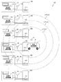
- FIG. 1 is a functional block diagram of an example of the power supply system according to the first embodiment.
- a vehicle 1 is, for example, an electric vehicle or a plug-in hybrid vehicle, a secondary battery 130 such as a lithium ion secondary battery or a nickel hydride secondary battery, and an in-vehicle communication device 2 for performing wireless communication.
- the in-vehicle communication device 2 includes a control unit 3, an antenna 4a (transmission / reception unit), a transmission processing unit 5, a power adjustment unit 6, a reception processing unit 7, and a power adjustment table 8A.
- the power supply apparatuses 91 to 9n include power supply side communication apparatuses 101 to 10n for performing wireless communication, respectively.
- the power supply side communication devices 101 to 10n include antennas 111 to 11n and communication units 121 to 12n, respectively.
- any one of the power feeding devices 91 to 9n when any one of the power feeding devices 91 to 9n is shown, it is referred to as a power feeding device 9. Further, when any one of the power supply side communication devices 101 to 10n is indicated, it is referred to as a power supply side communication device 10. In addition, when any one of the antennas 111 to 11n is shown, it is referred to as an antenna 11. Further, when any one of the communication units 121 to 12n is indicated, it is referred to as a communication unit 12.
- the function of the in-vehicle communication device 2 according to the first embodiment will be described.
- the in-vehicle communication device 2 is driven by power supplied from the secondary battery 130.
- the in-vehicle communication device 2 performs wireless communication with the power supply side communication devices 101 to 10n included in the power supply devices 91 to 9n.
- the control unit 3 controls the operations of the antenna 4a, the transmission processing unit 5, the power adjustment unit 6, and the reception processing unit 7.
- the control unit 3 searches for a power feeding device 9 that can communicate and accept power feeding from the power feeding devices 91 to 9n (whether the power feeding device 9 can receive a signal transmitted from the antenna 4a).
- An inquiry signal (for confirmation) is generated and output to the transmission processing unit 5.
- the inquiry signal is input to the antenna 4a via the transmission processing unit 5, and is transmitted from the antenna 4a to the power feeding apparatuses 91 to 9n by broadcast.
- control unit 3 controls the power adjustment unit 6 based on the value of the transmission output of the inquiry signal supplied to the antenna 4a stored in the power adjustment table 8A (hereinafter referred to as the transmission output value) to The adjustment unit 6 adjusts the transmission output of the inquiry signal.
- the control unit 3 controls the power adjusting unit 6 to repeatedly transmit the inquiry signal from the antenna 4a to the power feeding devices 91 to 9n while gradually reducing the transmission output of the inquiry signal.
- control unit 3 determines whether or not the response signal is received by the antenna 4a.
- the response signal is a signal transmitted from the power feeding device 9 to the vehicle 1 when the power feeding side communication device 10 receives the inquiry signal.
- the control unit 3 determines that the response signal is received from only one power supply device 9, the control unit 3 performs pairing (authentication processing) with the power supply device 9 that has transmitted the response signal.
- the determination of the number of power supply apparatuses 9 that have transmitted response signals includes, for example, an identifier in the response signal transmitted from the power supply apparatus 9.
- the vehicle-mounted communication apparatus 2 should just determine the number of the electric power feeders 9 which transmitted the response signal based on the kind of identifier which the received response signal contains.
- control unit 3 may perform control associated with transmission / reception of signals used for communication with the power supply device 9 and other devices.
- the antenna 4a transmits the input inquiry signal to the power supply apparatuses 91 to 9n by broadcast. Further, when receiving the response signal, the antenna 4 a outputs the received response signal to the reception processing unit 7.
- the antenna 4a may be used for transmission / reception of signals used for communication with the power supply device 9 and other devices in addition to the inquiry signal and the response signal.
- the transmission processing unit 5 converts the digital signal input from the control unit 3 into an analog signal for transmission from the antenna 4a, and outputs the analog signal to the antenna 4a.
- the transmission processing unit 5 converts an inquiry signal input as a digital signal from the control unit 3 into an analog signal and outputs the analog signal to the antenna 4a.
- the transmission processing unit 5 may encode the digital signal input from the control unit 3 and then convert it into an analog signal.
- the power adjustment unit 6 adjusts the transmission output of the signal transmitted from the antenna 4 a based on the control signal input from the control unit 3. For example, the power adjustment unit 6 adjusts the transmission output of the analog signal input from the transmission processing unit 5 according to the request for the control signal input from the control unit 3.
- the reception processing unit 7 converts the analog signal received by the antenna 4 a into a digital signal and outputs it to the control unit 3. For example, the reception processing unit 7 performs a process of converting a response signal input as an analog signal from the antenna 4 a into a digital signal and outputting the digital signal to the control unit 3.
- the reception processing unit 7 may convert the analog signal into a digital signal, decode the digital signal, and output the decoded digital signal to the control unit 3.
- the function of the power supply side communication device 10 will be described.
- the power supply side communication device 10 performs wireless communication with the in-vehicle communication device 2 included in the vehicle 1.
- the antenna 11 transmits a response signal input from the communication unit 12 to the vehicle 1. Further, when receiving the inquiry signal, the antenna 11 outputs the received inquiry signal to the communication unit 12.
- the antenna 11 may transmit and receive signals used for communication with the vehicle 1 and other devices in addition to the inquiry signal and the response signal.
- the communication unit 12 When the inquiry signal is input from the antenna 11, the communication unit 12 outputs a response signal to the antenna 11. However, the communication unit 12 does not output a response signal to the antenna 11 when the installed power feeding device 9 is in use.
- the communication unit 12 may perform control associated with transmission / reception of signals used for communication with the power supply device 9 and other devices in addition to the inquiry signal and the response signal.
- the communication unit 12 includes a control unit, a transmission processing unit, and a reception processing unit. And the control part of the communication part 12 produces
- the transmission processing unit of the communication unit 12 converts the response signal input as a digital signal into an analog signal and outputs the analog signal to the antenna 11.
- the reception processing unit of the communication unit 12 converts the inquiry signal input as an analog signal from the antenna 11 into a digital signal and outputs the digital signal to the control unit of the communication unit 12.
- FIG. 2 is a hardware configuration example of an embodiment of the communication apparatus.
- the communication device (the in-vehicle communication device 2 and the power supply side communication device 10) includes a control unit 201, a storage unit 202, a reading device 203, a recording medium 204, a display device 205, an input / output interface 206 (input / output I / O). F), a communication interface 207 (communication I / F), a power adjustment circuit 208, and an antenna 209. Each component is connected by a bus 200.
- the control unit 201, the storage unit 202, the reading device 203, the recording medium 204, the display device 205, the input / output interface 206 (input / output I / F), and the communication interface 207 (communication I / F) are collectively referred to as a computer.
- the control unit 201 controls the entire communication device.
- the control unit 201 of the in-vehicle communication device 2 functions as the control unit 3 in FIG.
- the control part 201 of the electric power feeding side communication apparatus 10 functions as a control part of the communication part 12 of FIG.
- the control unit 201 is, for example, a CPU, a multi-core CPU, an FPGA (Field Programmable Gate Array), a PLD (Programmable Logic Device), or the like.
- the storage unit 202 is, for example, a memory such as a ROM (Read Only Memory) and a RAM (Random Access Memory), or an HD (Hard Disk).
- the ROM stores a program such as a boot program.
- the RAM is used as a work area for the control unit 201.
- the HD stores an OS (Operating System), an application program, a program such as firmware, and various data.
- storage part 202 of the vehicle-mounted communication apparatus 2 has memorize
- the power adjustment table 8 ⁇ / b> A is not limited to the storage unit 202 of the in-vehicle communication device 2, and can be connected by another storage unit included in the vehicle 1 or the communication interface 207 as long as the control unit 201 of the in-vehicle communication device 2 can be accessed. May be stored in a server on the network 210.
- a communication control program may be stored in the storage unit 202 of the in-vehicle communication device 2. And when starting communication control, the control part 201 of the vehicle-mounted communication apparatus 2 reads a communication control program to RAM. Thereby, the control part 201 of the vehicle-mounted communication apparatus 2 functions as the control part 3 by using RAM as a work space.
- the communication control program is connected not only to the storage unit 202 of the in-vehicle communication device 2 but also to another storage unit included in the vehicle 1 or the communication interface 207 as long as the control unit 201 of the in-vehicle communication device 2 is accessible. May be stored in a server on the network 210.
- the communication control program may be stored in the storage unit 202 of the power supply side communication device 10. And when starting communication control, the control part 201 of the electric power feeding side communication apparatus 10 reads a communication control program to RAM. Thereby, the control part 201 of the electric power feeding side communication apparatus 10 functions as a control part of the communication part 12 by using RAM as a work space.
- the communication control program is not limited to the storage unit 202 of the power supply side communication device 10 but may be another storage unit included in the power supply device 9 or the communication interface 207 as long as the control unit 201 of the power supply side communication device 10 is accessible. It may be stored in a server on the network 210 connected by.
- HD Hard Disk Drive
- the reading device 203 is controlled by the control unit 201 and reads / writes data on the removable recording medium 204. Then, the reading device 203 of the in-vehicle communication device 2 may read the communication control program recorded in the recording medium 204 and store it in the storage unit 202 of the in-vehicle communication device 2. Further, the reading device 203 of the power supply side communication device 10 may read the communication control program recorded on the recording medium 204 and store it in the storage unit 202 of the power supply side communication device 10.
- the reading device 203 may be, for example, FDD (Floppy Disk Drive), CDD (Compact Disc Drive), DVDD (Digital Versatile Disk Drive), BDD (Blu-ray DiscUsU: registered trademark). It is.
- the recording medium 204 stores various data.
- the recording medium 204 is connected to the bus 200 via the reading device 203, and data is read / written by the control unit 201 controlling the reading device 203.
- the recording medium 204 may store a charge control program.
- the recording medium 204 is, for example, an FD (Floppy Disk), a CD (Compact Disc), a DVD (Digital Versatile Disk), a BD (Blu-ray Disk: registered trademark), and a flash memory.
- the display device 205 is connected to the bus 200 and is controlled by the control unit 201 to display various types of information.
- the display device 205 is, for example, a CRT (Cathode Ray Tube), an LCD (Liquid Crystal Display), a PDP (Plasma Display Panel), or an OELD (Organic Electroluminescence Display).
- the input / output interface 206 is connected to, for example, a keyboard, a mouse, a touch panel, a scanner, and a printer, receives information input by the connected device, and outputs the information to the control unit 201 via the bus 200. In addition, when the information output from the control unit 201 is input via the bus 200, the input / output interface 206 outputs the information to various connected devices.
- the communication interface 207 communicatively connects a communication device and another device via a network 210 such as power line communication, LAN (Local Area Network), wireless communication, or the Internet.
- the communication interface 207 of the in-vehicle communication device 2 functions as the transmission processing unit 5 and the reception processing unit 7 in FIG.
- the communication interface 207 of the power supply side communication device 10 functions as a transmission processing unit and a reception processing unit of the communication unit 12 in FIG.
- the communication interface 207 is, for example, a modem or a LAN adapter.
- the power adjustment circuit 208 adjusts the transmission output of the analog signal input from the control unit 201 via the communication interface 207, and outputs the analog signal to the antenna 209.
- the power adjustment circuit 208 functions as the power adjustment unit 6 in FIG.
- the power adjustment circuit 208 is, for example, an amplifier circuit that can switch the amplification factor.
- the antenna 209 transmits and receives radio signals.
- the antenna 209 of the vehicle-mounted communication apparatus 2 functions as the antenna 4a of FIG.
- the antenna 209 of the power supply side communication device 10 functions as the antenna 11 of FIG.
- the antenna 209 includes at least one of a non-directional antenna such as a whip antenna, a directional antenna such as a dipole antenna, and a directivity-switchable antenna such as an array antenna (registered trademark).
- FIG. 3 is a data example of a power adjustment table used for setting the transmission power value of the inquiry signal.
- the power adjustment table 8A according to the first embodiment will be described.
- the power adjustment table 8A shown in FIG. 3 for example, as shown in the power adjustment table 301, three output levels and transmission output values [W] corresponding to the respective output levels (hereinafter, [W] are omitted). .) Is stored.
- the output levels are not limited to three, and any number of two or more may be stored.
- the output level and the transmission output value corresponding to each output level are arbitrarily set by the user.
- the output level is an identifier for identifying the transmission output value stored in the power adjustment table 301.
- level 1, level 2, and level 3 are set as output levels.
- the transmission output value is a value that is output to the power adjustment unit 6 as the output of the inquiry signal when the control unit 3 selects the output level.
- the power adjustment unit 6 converts the power of the inquiry signal input from the transmission processing unit 5 into the input transmission output value and outputs it to the antenna 4a.
- the transmission output value is set such that A [W] ⁇ B [W] ⁇ C [W].
- an output set value and a power value [W] (hereinafter, [W] is omitted) are stored. good.
- the power value corresponding to each output setting value is arbitrarily set by the user.
- the output set value is an identifier for identifying the power value stored in the power adjustment table 302.
- the upper limit value is an identifier corresponding to the power value at the maximum output of the transmission output value.
- the differential power value indicates the difference between the original transmission output value when the output level of the transmission output value changes by one step and the transmission output value after the change.
- the lower limit value is an identifier corresponding to the power value at the minimum output of the transmission output value.
- the power value is a power value corresponding to each output setting value.
- D [W], E [W], and F [W] are set as the power values.
- FIG. 4 is an explanatory diagram illustrating an example of processing for specifying a communication destination according to the first embodiment.
- FIG. 5 is an explanatory diagram showing an example of display contents of the display device.
- the antenna 4a is a non-directional antenna in FIG. 4 and that the values shown in the power adjustment table 301 in FIG. 3 are stored in the power adjustment table 8A.
- the antenna 4a is illustrated separately from the in-vehicle communication device 2, but is included in the in-vehicle communication device 2.
- the antennas 111 to 11n are illustrated separately from the power supply side communication devices 101 to 10n, but are included in the power supply side communication devices 101 to 10n, respectively.
- a plurality of power supply apparatuses 9 are installed in the power supply facility 400.
- 4 are positions where the vehicle 1 is parked when the secondary battery 130 provided in the vehicle 1 is charged in a non-contact manner.
- Coils 411 to 41n in FIG. 4 are coils for transmitting and receiving power and transmitting and receiving communication signals in a non-contact manner with a coil (not shown) provided in the vehicle 1.
- the power supply area 40 is referred to.
- any one of the coils 411 to 41n it is called a coil 41.
- the inquiry signal of the transmission output C [W] corresponding to the transmission output value of level 3 is transmitted to the broadcast from the antenna 4a of the vehicle-mounted communication device 2.
- the antennas 112 to 115 within the range (hereinafter referred to as a communication area) included in the level 3 broken line shown in FIG. 4 receive the inquiry signal transmitted from the in-vehicle communication device 2.
- the power supply side communication devices 102 to 105 transmit response signals including the identifiers of the power supply devices 92 to 95 to which the power supply side communication devices 102 to 105 belong to the in-vehicle communication device 2.
- the in-vehicle communication device 2 receives response signals transmitted from the power supply devices 92 to 95. Then, the in-vehicle communication device 2 reads the identifier included in the response signal, and determines the power supply devices 92 to 95 that are the transmission source of the response signal. Then, as shown in the display screen 501 of FIG. 5, the in-vehicle communication device 2 uses power supply devices 92 to 95 that can be connected to the display device 205 of the in-vehicle communication device 2 (may be a display device mounted on the vehicle 1). indicate.
- the in-vehicle communication device 2 transmits a transmission output inquiry signal corresponding to the transmission output value of level 2 from the antenna 4a to the broadcast.
- the antennas 113 to 115 in the level 2 communication area shown in FIG. 4 receive the inquiry signal.
- the power supply side communication devices 103 to 105 transmit response signals including the identifiers of the power supply devices 93 to 95 to which the power supply side communication devices 103 to 105 belong to the in-vehicle communication device 2.
- the in-vehicle communication device 2 receives the response signals transmitted from the power feeding devices 93 to 95.
- the in-vehicle communication device 2 reads the identifier included in the response signal and determines the power supply devices 93 to 95 that are the transmission source of the response signal. Then, the in-vehicle communication device 2 displays the power feeding devices 93 to 95 that can be communicably connected to the display device 205 of the in-vehicle communication device 2.
- the in-vehicle communication device 2 transmits an inquiry signal of transmission output corresponding to the transmission output value of level 1 from the antenna 4a to the broadcast.
- the antenna 114 in the communication area of level 1 shown in FIG. 4 receives the inquiry signal.
- the power supply side communication device 104 transmits a response signal including the identifier of the power supply device 94 to which it belongs to the in-vehicle communication device 2.
- the in-vehicle communication device 2 receives only the response signal transmitted from the power supply device 94.
- the in-vehicle communication device 2 displays a power supply device 94 capable of communication connection on the display device 205 of the in-vehicle communication device 2 as shown in a display screen 502 in FIG.
- the in-vehicle communication device 2 identifies the power supply side communication device 104 as a communication destination and performs pairing.
- the power feeding device 94 that communicates with the vehicle 1 is displayed on the display screen of the display device 205 of the in-vehicle communication device 2 as a display screen 503.
- a display screen 504 indicating that communication with the vehicle 1 is performed may be displayed on the display screen of the display device 205 of the power supply side communication device 10 of the power supply device 94.
- the in-vehicle communication device 2 receives the inquiry signal to be transmitted stepwise (gradually) to each power supply side communication device 10 until the power supply side communication device 10 that transmits a response signal to the inquiry signal becomes one unit. Reduce the transmission output.
- the in-vehicle communication device 2 pairs with the power supply side communication device 10 when the power supply side communication device 10 having a response signal returned becomes one.
- the in-vehicle communication device 2 displays the identification number (read from the identifier included in the response signal) of the power supply device 9 to which the paired power supply side communication device 10 belongs to the display device 205 of the in-vehicle communication device 2.
- the in-vehicle communication device 2 guides the user to the power supply device 9 to which the paired power supply side communication device 10 belongs.
- the user moves the vehicle 1 to the position of the power supply device 9 displayed on the display device 205 of the in-vehicle communication device 2, thereby charging the secondary battery 130 included in the vehicle 1 with the power supply device 9 capable of communication connection. can do.
- the power supply side communication device 10 Even if the power supply side communication device 10 is within the range in which the inquiry signal from the in-vehicle communication device 2 can be received, and the power supply device 9 to which the power supply side communication device 10 belongs is in use, the power supply side communication device 10 It is not necessary to send back a response signal. Thereby, only the response signal from the power feeding device 9 that can be communicably connected to the vehicle 1 can be transmitted, and only the power feeding device 9 that can be communicably connected to the vehicle 1 can be notified.
- a plurality of power supply devices 9 to which the vehicle 1 can be connected for communication are displayed on the display device 205 of the in-vehicle communication device 2.
- the user may select the power supply side communication device 10 as the communication destination from the power supply devices 9 displayed on the display device 205 of the in-vehicle communication device 2.
- the vehicle-mounted communication apparatus 2 makes the vehicle-mounted communication apparatus 2 which the vehicle 1 has, and the electric power feeding side communication apparatus 10 which the selected electric power feeding apparatus 9 has paired.
- the in-vehicle communication device 2 may not display the display screen 501.
- the power feeding device 9 that does not include the vehicle 1 in the signal communication area is not recognized as the power feeding device 9 that can be communicably connected in the in-vehicle communication device 2.
- the transmission output of the inquiry signal is reduced stepwise using the following equation (1) to establish communication connection
- Possible power supply devices 9 may be specified.
- the response signal is accepted only within a predetermined time after the inquiry signal is transmitted.
- the in-vehicle communication device 2 performs pairing with the power supply device 9.
- the in-vehicle communication device 2 sends an inquiry signal whose transmission output is smaller than the inquiry signal transmitted last time to an unspecified number of power supplies. Transmit to device 9 (transmit to broadcast).
- the clock of the CPU of the control unit 201 of the in-vehicle communication device 2 may be counted, or a time counting unit such as a counter circuit may be provided separately.
- a time counting unit such as a counter circuit
- any method may be used as appropriate as long as mutual authentication is possible, such as a 3-way handshake.
- any method may be used as appropriate as long as mutual authentication is possible, such as a 3-way handshake.
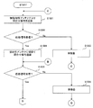
- FIG. 6 is a flowchart illustrating the processing contents for specifying the communication destination according to the first embodiment.
- the flowchart shown in FIG. 6 shows the process of specifying the communication destination described with reference to FIG. The following description will be given with reference to FIG. Further, in the following description, it is assumed that the antenna 4a is an omnidirectional antenna and that the values shown in the power adjustment table 301 in FIG. 3 are stored in the power adjustment table 8A.
- the in-vehicle communication device 2 of the vehicle 1 determines whether or not the vehicle 1 has entered the power supply facility 400 (S601). Then, the in-vehicle communication device 2 repeats the process of S601 until it is determined that the vehicle 1 has entered the power supply facility 400 (No in S601).
- the in-vehicle communication device 2 is, for example, that the vehicle 1 has entered the power supply facility 400 when an instruction to start a process for specifying a communication destination is input by the user via the input / output interface 206 of the in-vehicle communication device 2.
- a determination is made (Yes in S601), and an inquiry signal is transmitted to the broadcast (S602).
- the transmission output of the inquiry signal at this time is level 3, and the inquiry signal is transmitted over a wide range.
- an infrared transmitter is installed near the entrance of the power supply facility 400, and the vehicle 1 is provided with an infrared receiver.
- the in-vehicle communication device 2 may determine that the vehicle 1 has entered the power supply facility 400 when receiving a signal that the vehicle 1 has entered the power supply facility 400 from the infrared receiver. Note that the present invention is not limited to this, and if it can be determined that the vehicle 1 has entered the power supply facility 400, a method using various sensors may be selected as appropriate.
- the vehicle-mounted communication apparatus 2 determines whether the response signal transmitted from the electric power feeder 9 was received (S603). If the in-vehicle communication device 2 determines that the response signal transmitted from the power supply device 9 has not been received (No in S603), the user moves the vehicle 1 in the direction of each power supply device 9 (S604), and then S602. Perform the following process. Note that the movement of the vehicle 1 by the user is arbitrarily performed by the user during the process of specifying the communication destination shown in FIG.
- the vehicle-mounted communication device 2 determines whether the response signal is received from only one power supply device 9 or not. (S605). And if the vehicle-mounted communication apparatus 2 determines with having received the response signal from the several electric power feeder 9, (No in S605), it will determine whether the transmission output of an inquiry signal will be lowered
- the pairing process is executed manually (S608).
- the in-vehicle communication device 2 receives response signals from the plurality of power supply devices 9 when the transmission output is an inquiry signal whose level is 1, the display screen 501 is displayed on the display screen of the display device 205 of the in-vehicle communication device 2.
- a plurality of power supply apparatuses 9 that can be connected to each other are displayed.
- the user selects the power supply device 9 to be connected for communication from among the plurality of power supply devices 9 displayed on the display device 205 of the in-vehicle communication device 2.
- the in-vehicle communication device 2 performs a pairing process with an arbitrary power supply side communication device 10.
- the vehicle-mounted communication apparatus 2 determines whether pairing with the selected electric power feeding side communication apparatus 10 was completed (S609). If the in-vehicle communication device 2 determines that pairing with the selected power supply side communication device 10 has failed (S609), the in-vehicle communication device 2 executes the processing of S608 and selects a power supply device 9 different from the power supply device 9 selected last time by the user. Let In addition, when the in-vehicle communication device 2 cannot be paired with all the communication connectable power supply devices 9, the communication connection may be impossible and the processing may be terminated, or the processing of S604 may be executed again.
- the reason why pairing with the power feeding device 9 displayed on the display screen 501 is not possible is that the vehicle 1 requests pairing to the power feeding device 9 because the selected power feeding device 9 and another vehicle have paired first.
- the case where the signal etc. for doing so are exclusive is considered.
- the in-vehicle communication device 2 determines that the power supply side communication device 10 of the selected power supply device 9 has been paired (Yes in S609), the power supply device 9 having the power supply side communication device 10 paired with the display device 205. The identification number of the paired power supply device 9 is displayed. As a result, the user is guided to the paired power supply device 9. Thereafter, when the vehicle 1 is moved to the power supply area 40 of the power supply device 9 paired by the user, the vehicle 1 transmits a signal indicating that charging of the secondary battery 130 of the vehicle 1 is started to the paired power supply device 9. (S610). Thereby, charging of the secondary battery 130 of the vehicle 1 is started. During charging, a signal including information necessary for controlling charging is transmitted and received between the in-vehicle communication device 2 and the paired power supply side communication device 10.
- the in-vehicle communication device 2 when the inquiry signal is transmitted to the broadcast while the transmission output is gradually reduced, and the response signal is received from only one power supply device 9, the power supply device 9 Pairing is automatically performed with the power supply side communication device 10 having the power supply. Thereby, the in-vehicle communication device 2 can automatically identify the power supply device 9 closest to the vehicle 1 among the power supply devices 9 capable of communication connection as the power supply device 9 of the communication destination and perform pairing.
- the power supply device 9 closest to the vehicle 1 among the power supply devices 9 that can be connected to each other is automatically specified as the power supply device 9 that is the communication destination.
- the device 9 and the plurality of vehicles 1 can be in one-to-one correspondence.
- FIG. 7 is a functional block diagram of an example of the power supply system according to the second embodiment.
- the in-vehicle communication device 2 according to the second embodiment includes an omnidirectional antenna 4b and a directional antenna 4c instead of the antenna 4a of the in-vehicle communication device 2 according to the first embodiment. Furthermore, the in-vehicle communication device 2 according to the second embodiment includes an antenna switching unit 13 that switches an antenna used for signal transmission / reception between the antenna 4b and the antenna 4c.
- the antenna 4b is an omnidirectional antenna, and transmits an inquiry signal input from the power adjustment unit 6 to the power supply apparatuses 91 to 9n by broadcast. Further, when receiving the response signal, the antenna 4 b outputs the received response signal to the reception processing unit 7.
- the antenna 4b may be used for transmission / reception of signals used for communication with the power supply device 9 and other devices in addition to the inquiry signal and the response signal.
- the antenna 4 c is an antenna having directivity, and is installed so that the directivity faces the traveling direction of the vehicle 1.
- an antenna having a main lobe and a back lobe may be used as the antenna 4c.
- the antenna 4 c is preferably installed so that the main lobe faces the front of the vehicle 1. Thereby, when the vehicle 1 is moving forward, the directivity in the traveling direction of the antenna 4c is ensured by the main lobe. When the vehicle 1 is backing, the directivity in the traveling direction of the antenna 4c is ensured by the back lobe.
- the traveling direction when the vehicle 1 is backing may have the same directivity as the traveling direction when the vehicle 1 is moving forward. good.
- the directivity of the antenna 4c is not limited to the traveling direction of the vehicle 1, and may be set so as to face an arbitrary direction of the user.
- the traveling direction of the vehicle 1 is assumed to be a forward direction.
- the directivity of the antenna 4c shall be facing the front.
- the antenna 4c transmits the inquiry signal input from the power adjustment unit 6 to the power supply apparatuses 91 to 9n by broadcast. Further, when receiving the response signal, the antenna 4 c outputs the received response signal to the reception processing unit 7.
- the antenna 4c may be used for transmission / reception of signals used for communication with the power feeding device 9 and other devices in addition to the inquiry signal and the response signal.
- the antenna switching unit 13 switches the antenna used for signal transmission / reception between the antenna 4b and the antenna 4c.
- FIG. 2 is a hardware configuration example of an embodiment of the communication apparatus.
- the antenna 209 of the in-vehicle communication device 2 includes a directional antenna and an omnidirectional antenna, and a switching circuit that switches use of each. Thereby, the antenna 209 of the in-vehicle communication device 2 transmits and receives radio signals by switching between the non-directional antenna and the directional antenna. And the antenna 209 of the vehicle-mounted communication apparatus 2 of Embodiment 2 functions as the antenna 4b, the antenna 4c, and the antenna switching part 13 of FIG. Moreover, you may use the coil with which the vehicle 1 is provided instead of the antenna 4b of the vehicle-mounted communication apparatus 2 as the antenna 4b.
- FIG. 8 is a data example of a power adjustment table used for setting the transmission power value of the inquiry signal.
- the output level ⁇ of the omnidirectional antenna 4b and the transmission output value ⁇ [W] (hereinafter referred to as the output level ⁇ ). , [W] is omitted).
- the transmission output value ⁇ corresponding to the output level is arbitrarily set by the user.
- the output level ⁇ is an identifier for identifying the transmission output value ⁇ of the antenna 4b stored in the power adjustment table 801.
- level 3 is set as the output level ⁇ .
- the transmission output value ⁇ is a value that is output to the power adjustment unit 6 as the output of the inquiry signal when the control unit 3 sets the output level ⁇ to level 3.
- the power adjustment unit 6 sets the power of the inquiry signal input from the transmission processing unit 5 to the input transmission output value ⁇ and outputs it to the antenna 4b.
- C [W] is set as the transmission output value ⁇ .
- the power adjustment table 8B includes, for example, as shown in the power adjustment table 801, three output levels ⁇ of the directional antenna 4c and transmission output values ⁇ [W] (hereinafter referred to as the output levels ⁇ ). , [W] is omitted).
- the output level ⁇ is not limited to three but may be stored in an arbitrary number of two or more. Further, the output level ⁇ and the transmission output value ⁇ corresponding to each output level ⁇ are arbitrarily set by the user.
- the output level ⁇ is an identifier for identifying the transmission output value ⁇ stored in the power adjustment table 801.
- level 1, level 2, and level 3 are set as the output level ⁇ .
- the transmission output value ⁇ is a value that is output to the power adjustment unit 6 as the output of the inquiry signal when the control unit 3 selects the output level ⁇ .
- the power adjustment unit 6 outputs the power of the inquiry signal input from the transmission processing unit 5 to the antenna 4c as the input transmission output value ⁇ .
- the transmission output value ⁇ is set such that A [W] ⁇ B [W] ⁇ C [W].
- the output set value ⁇ and the power value ⁇ [W] may be set.
- the power value ⁇ corresponding to each output set value ⁇ is arbitrarily set by the user.
- the output set value ⁇ is an identifier for identifying the power value ⁇ stored in the power adjustment table 802.
- the upper limit value is an identifier corresponding to the power value at the maximum output of the transmission output value ⁇ .
- the differential power value indicates the power value of the difference between the original transmission output value ⁇ when the output level of the transmission output value ⁇ is changed by one step and the transmission output value ⁇ after the change.
- the lower limit value is an identifier corresponding to the power value at the minimum output of the transmission output value ⁇ .
- the power value ⁇ is a power value corresponding to each output set value ⁇ .
- D [W], E [W], and F [W] are set as the power value ⁇ .
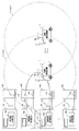
- FIG. 9 is an explanatory diagram illustrating an example of processing for specifying a communication destination according to the second embodiment.
- the antenna 4b is an omnidirectional antenna
- the antenna 4c is a directional antenna
- the power adjustment table 8B has values shown in the power adjustment table 801 of FIG. It is assumed that it is stored.
- the same components as those of the first embodiment described with reference to FIG. Further, it is assumed that the vehicle 1 is located in the communication area of the antennas 111 to 11n.
- the inquiry signal of the transmission output value C [W] corresponding to the transmission output value ⁇ of level 3 is broadcast from the antenna 4b of the in-vehicle communication device 2.
- the antennas 112 and 113 in the communication area of level 3 shown in FIG. 9 receive the inquiry signal transmitted from the in-vehicle communication device 2.
- the power supply side communication devices 102 and 103 transmit a response signal to the in-vehicle communication device 2.
- the in-vehicle communication device 2 receives the response signal transmitted from the power feeding devices 92 and 93.
- the in-vehicle communication device 2 determines that the vehicle 1 has entered the power supply facility 400.
- the in-vehicle communication device 2 reads the identifier included in the response signal and determines the power supply devices 92 and 93 that are the transmission source of the response signal. Then, the in-vehicle communication device 2 determines that the power feeding devices 92 and 93 are communicable, and the power feeding device 92 that can be communicably connected to the display device 205 of the in-vehicle communication device 2 (or a display device mounted on the vehicle 1). , 93 are displayed.
- the in-vehicle communication device 2 switches the antenna to be used to the antenna 4c. Then, an inquiry signal of the transmission output C [W] corresponding to the transmission output value ⁇ of level 3 is transmitted from the antenna 4c to the broadcast.
- the antennas 112 and 113 in the L3 communication area shown in FIG. 9 receive the inquiry signal transmitted from the in-vehicle communication device 2. Then, the power supply side communication devices 102 and 103 transmit a response signal to the in-vehicle communication device 2. Thereby, the in-vehicle communication device 2 receives the response signal transmitted from the power feeding devices 92 and 93.
- the in-vehicle communication device 2 reads the identifier included in the response signal, and determines that the power supply devices 92 and 93 that are the transmission source of the response signal are power supply devices that can be communicably connected. Further, the in-vehicle communication device 2 displays power supply devices 92 and 93 that can be connected to the display device 205 of the in-vehicle communication device 2.
- the in-vehicle communication device 2 transmits an inquiry signal of the transmission output B [W] corresponding to the transmission output value ⁇ of level 2 from the antenna 4c to the broadcast.
- the antennas 112 and 113 in the L2 communication area shown in FIG. 9 receive the inquiry signal transmitted from the in-vehicle communication device 2.
- the power supply side communication devices 102 and 103 transmit a response signal to the in-vehicle communication device 2.
- the in-vehicle communication device 2 receives the response signal transmitted from the power feeding devices 92 and 93.
- the in-vehicle communication device 2 reads the identifier included in the response signal, and determines that the power supply devices 92 and 93 that are the transmission source of the response signal are power supply devices that can be communicably connected. Further, the in-vehicle communication device 2 displays power supply devices 92 and 93 that can be connected to the display device 205 of the in-vehicle communication device 2.
- the in-vehicle communication device 2 transmits an inquiry signal of the transmission output A [W] corresponding to the transmission output value ⁇ of level 1 from the antenna 4c to the broadcast.
- the antenna 113 in the communication area of L1 shown in FIG. 9 receives the inquiry signal transmitted from the in-vehicle communication device 2.
- the power supply side communication device 103 transmits a response signal to the in-vehicle communication device 2.
- the in-vehicle communication device 2 receives the response signal transmitted from the power feeding device 93.
- the vehicle-mounted communication apparatus 2 reads the identifier contained in a response signal, and determines with the power supply apparatus 93 of the transmission source of a response signal being a power supply apparatus with which communication connection is possible.
- the in-vehicle communication device 2 displays a power supply device 93 that can be connected to the display device 205 of the in-vehicle communication device 2.
- the in-vehicle communication device 2 specifies (selects) the power supply side communication device 104 as a communication destination and performs pairing. When the pairing is completed, the in-vehicle communication device 2 displays on the display device 205 of the in-vehicle communication device 2 a display indicating that the pairing is performed with the power feeding device 93 that communicates with the vehicle 1.
- the transmission output of the inquiry signal is stepwise using the equation (1) when the antenna 4c is used. It is also possible to specify a power supply device 9 that can be reduced in size for communication connection.
- FIG. 10 is a flowchart illustrating processing contents for specifying a communication destination according to the second embodiment.
- the flowchart shown in FIG. 10 shows the process of specifying the communication destination described with reference to FIG.
- the antenna 4b is an omnidirectional antenna
- the antenna 4c is a directional antenna
- the power adjustment table 8B stores values shown in the power adjustment table 801 of FIG. It will be explained as a thing.
- the in-vehicle communication device 2 of the vehicle 1 transmits an inquiry signal to the broadcast from the non-directional antenna 4b when an instruction to start a process for specifying a communication destination is input by the user (1001).
- the transmission output of the inquiry signal at this time is level 3, and the inquiry signal is transmitted over a wide range.
- vehicle-mounted communication apparatus 2 determines whether the response signal was received from the electric power feeder 9 (S1002).
- S1001 Perform the following process. Note that the movement of the vehicle 1 by the user is arbitrarily performed by the user during the process of specifying the communication destination shown in FIG. Further, when it is determined that the response signal transmitted from the power feeding device 9 has not been received (No in S1002), the in-vehicle communication device 2 may be configured to execute the process of S1001 after a certain time.
- the vehicle-mounted communication apparatus 2 if it determines with the vehicle-mounted communication apparatus 2 having received the response signal transmitted from the 1 or more power supply apparatus 9 (it is Yes in S1002), it will determine with the vehicle 1 being located in the power supply facility 400.
- the antenna to be used is switched to the antenna 4c and an inquiry signal is transmitted.
- the inquiry signal transmission output at this time is set to level 3, and the inquiry signal is transmitted over a wide range (S1004).
- vehicle-mounted communication apparatus 2 determines whether the response signal was received from the electric power feeder 9 (S1005).
- the in-vehicle communication device 2 determines that the response signal transmitted from the power supply device 9 has not been received (No in S1005), after the user moves the vehicle 1 in the direction of each power supply device 9 (S1006), S1001 Perform the following process. Note that the movement of the vehicle 1 by the user is arbitrarily performed by the user during the process of specifying the communication destination shown in FIG. Further, when it is determined that the response signal transmitted from the power feeding device 9 has not been received (No in S1002), the in-vehicle communication device 2 may be configured to execute the process of S1001 after a certain time.
- the in-vehicle communication apparatus 2 performs the processes of S605 to S611 shown in FIG.
- the inquiry signal is first transmitted by the omnidirectional antenna 4b. Accordingly, it is determined whether or not the power feeding device 9 is in the communication area of the vehicle 1. When the power feeding device 9 is in the communication area of the vehicle 1, communication using the antenna 4 c having directivity automatically is performed. The process can be shifted to the process of specifying the previous power supply device 9.
- one or more power supply devices 9 that can be connected to communication are specified. To do.
- the specified power feeding device 9 is in a direction different from the traveling direction of the vehicle 1, the direction of the power feeding device 9 is indicated on the display device 205 of the vehicle 1, and the traveling direction of the vehicle 1 is identified. Guide the user to change direction. Thereafter, when the traveling direction of the vehicle 1 is directed to the specified power supply device 9, the process may be shifted to a process of specifying the communication destination power supply device 9 using the antenna 4 c having directivity.
- the power feeding device 9 can be efficiently captured in the main lobe of the radio wave that transmits the inquiry signal of the antenna 4c having directivity.
- map information in the power supply facility 400 is obtained when the in-vehicle communication device 2 connects to a server in the power supply facility 400 when the vehicle 1 enters the power supply facility 400.
- the vehicle-mounted communication apparatus 2 discriminate
- the position of the power supply device 9 may be determined based on the reception intensity of the response signal received from the power supply device 9 and the direction in which the response signal is transmitted.
- the in-vehicle communication device 2 of the vehicle 1 and the power supply side communication device 10 of the power supply device 9 are paired using the antenna 4c having directivity.
- the antenna that transmits the inquiry signal has directivity
- the power feeding device 9 that searches whether communication connection is possible is narrowed down in advance by the directivity of the antenna. Therefore, in the second embodiment, it is possible to narrow down to the power feeding device 9 in the traveling direction of the vehicle 1 and to search whether the communication connection with the vehicle 1 is possible or not. Therefore, the communication device for specifying the power feeding device 9 of the communication destination The processing load can be reduced.
- the omnidirectional antenna 4b may be omitted.
- the process from S1004 may be started using the antenna 4c having directivity.
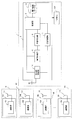
- FIG. 11 is a functional block diagram of an example of the power supply system according to the third embodiment.
- FIG. 11 the same functions as those of the in-vehicle communication device 2 according to the second embodiment described in FIG.
- the functions of the power supply side communication devices 101 to 10n according to the third embodiment are the same as the functions of the power supply side communication devices 101 to 10n according to the first embodiment described in FIG. The description is omitted.
- the in-vehicle communication device 2 according to the third embodiment instead of the antenna 4b, the antenna 4c, and the antenna switching unit 13 of the in-vehicle communication device 2 according to the second embodiment, the directivity of the antenna 4d and the directivity of the antenna 4d are switched. And a directivity switching unit for switching the characteristics.
- the antenna 4d is switchable in directivity, and transmits an inquiry signal input from the power adjustment unit 6 to the power supply apparatuses 91 to 9n in a broadcast manner.
- the directivity switching unit 14 sets the main lobe so as to face the traveling direction of the vehicle 1. Further, when receiving the response signal, the antenna 4 d outputs the received response signal to the reception processing unit 7.
- the antenna 4d may be used for transmission / reception of signals used for communication with the power supply device 9 and other devices in addition to the inquiry signal and the response signal.
- the directivity switching unit 14 performs control to switch the directivity of the antenna 4d.
- FIG. 2 is a hardware configuration example of an embodiment of the communication apparatus.
- the antenna 209 of the in-vehicle communication device 2 includes an antenna that can switch directivity and a directivity switching circuit that switches the directivity of the antenna. Thereby, the antenna 209 of the in-vehicle communication device 2 transmits and receives radio signals by switching the directivity of the antenna.
- the antenna 209 of the in-vehicle communication device 2 functions as the antenna 4d and the directivity switching unit 14 in FIG. Further, as the antenna 4d of the in-vehicle communication device 2, a power feeding coil provided in the vehicle 1 may be used.
- a reactance value adjustment circuit may be used as the directivity switching circuit.
- the configuration of the antenna 209 is not particularly limited as long as the antenna 209 is a combination of an antenna capable of switching directivity and a directivity switching circuit.
- the configuration of the third embodiment is a configuration in which the antenna 4b is replaced with the antenna 4d in a non-directional state and the antenna 4c is replaced with a state in which the antenna 4d has directivity in the second embodiment.
- the operation of the third embodiment is an operation in which the directivity of the antenna is switched instead of switching the antenna in the process of S1004 in FIG. 10 in the process of specifying the communication destination of the second embodiment.
- the same operation as that of the second embodiment is realized by changing the directivity of the antenna 4d instead of the configuration of switching the antenna 4b and the antenna 4c of the second embodiment. Thereby, the same effect as Embodiment 2 can be acquired with one antenna.
- the power supply device capable of communication connection is displayed on the display device 205 of the in-vehicle communication device 2.
- the user arbitrarily selects one of the displayed power supply apparatuses that can be connected to the communication, and enters one of the power supply areas 401 to 40n. Thereafter, the processing of S602 to S611 shown in FIG. 6 is performed. Since the power supply side communication device 10 corresponding to the power supply area 40 selected by the user is closest to the vehicle, the power supply side communication device 10 corresponding to the power supply area 40 selected by the user is communicated with by performing the processing of S602 to S611. Specified.
- the power supply device capable of communication connection is displayed on the display device 205 of the in-vehicle communication device 2.
- the user arbitrarily selects one of the displayed power supply apparatuses that can be connected to the communication, and enters one of the power supply areas 401 to 40n.
- the inquiry signal is transmitted by switching to the directional antenna (S1004). Since the power supply side communication device 10 corresponding to the power supply area 40 selected by the user is closest to the vehicle, the power supply side communication device 10 corresponding to the power supply area 40 selected by the user is set as the communication destination by performing the processing from S1004. Identified.
- the direction of the main lobe of the antenna having directivity is not limited to the traveling direction of the vehicle 1.
Landscapes
- Engineering & Computer Science (AREA)
- Power Engineering (AREA)
- Transportation (AREA)
- Mechanical Engineering (AREA)
- Computer Networks & Wireless Communication (AREA)
- Life Sciences & Earth Sciences (AREA)
- Sustainable Development (AREA)
- Sustainable Energy (AREA)
- Signal Processing (AREA)
- General Health & Medical Sciences (AREA)
- Computing Systems (AREA)
- Medical Informatics (AREA)
- Health & Medical Sciences (AREA)
- Charge And Discharge Circuits For Batteries Or The Like (AREA)
- Electric Propulsion And Braking For Vehicles (AREA)
- Variable-Direction Aerials And Aerial Arrays (AREA)
- Transceivers (AREA)
- Transmitters (AREA)
- Radio Transmission System (AREA)
- Traffic Control Systems (AREA)
- Mobile Radio Communication Systems (AREA)
Abstract
La présente invention porte sur un dispositif de communication monté sur véhicule (2) qui émet un signal de demande sur une diffusion tout en réduisant de manière incrémentale la sortie d'émission, et lorsqu'un signal de réponse est reçu en provenance seulement d'un dispositif d'alimentation électrique (9), le dispositif de communication monté sur véhicule (2) est automatiquement apparié avec un dispositif de communication côté alimentation électrique (10) du dispositif d'alimentation électrique (9).
Priority Applications (2)
| Application Number | Priority Date | Filing Date | Title |
|---|---|---|---|
| US14/412,587 US20150165923A1 (en) | 2012-07-11 | 2013-07-01 | In-vehicle communication device and communication method |
| EP13816235.9A EP2874322A1 (fr) | 2012-07-11 | 2013-07-01 | Dispositif de communication monté sur véhicule, et procédé de communication |
Applications Claiming Priority (2)
| Application Number | Priority Date | Filing Date | Title |
|---|---|---|---|
| JP2012-155189 | 2012-07-11 | ||
| JP2012155189A JP5849876B2 (ja) | 2012-07-11 | 2012-07-11 | 車載通信装置、および通信方法 |
Publications (1)
| Publication Number | Publication Date |
|---|---|
| WO2014010447A1 true WO2014010447A1 (fr) | 2014-01-16 |
Family
ID=49915911
Family Applications (1)
| Application Number | Title | Priority Date | Filing Date |
|---|---|---|---|
| PCT/JP2013/067987 Ceased WO2014010447A1 (fr) | 2012-07-11 | 2013-07-01 | Dispositif de communication monté sur véhicule, et procédé de communication |
Country Status (4)
| Country | Link |
|---|---|
| US (1) | US20150165923A1 (fr) |
| EP (1) | EP2874322A1 (fr) |
| JP (1) | JP5849876B2 (fr) |
| WO (1) | WO2014010447A1 (fr) |
Cited By (4)
| Publication number | Priority date | Publication date | Assignee | Title |
|---|---|---|---|---|
| JP2015177599A (ja) * | 2014-03-13 | 2015-10-05 | Ihi運搬機械株式会社 | 給電システム用プログラムと給電装置と駐車装置用プログラムと駐車装置 |
| WO2015185244A3 (fr) * | 2014-06-05 | 2016-08-25 | Siemens Aktiengesellschaft | Moyens et procédés pour établir une liaison associative |
| CN108988505A (zh) * | 2018-07-25 | 2018-12-11 | 天津工业大学 | 一种电动汽车大功率动态无线充电系统 |
| US20210241632A1 (en) * | 2017-02-24 | 2021-08-05 | At&T Mobility Ii Llc | Navigation systems and methods for drones |
Families Citing this family (22)
| Publication number | Priority date | Publication date | Assignee | Title |
|---|---|---|---|---|
| USD1009775S1 (en) | 2014-10-15 | 2024-01-02 | Maxeon Solar Pte. Ltd. | Solar panel |
| JP5979309B2 (ja) * | 2013-03-29 | 2016-08-24 | 日産自動車株式会社 | 非接触給電システム |
| WO2015045141A1 (fr) | 2013-09-30 | 2015-04-02 | 日産自動車株式会社 | Dispositif d'alimentation électrique sans fil et dispositif d'assistance au stationnement |
| JP2015144529A (ja) * | 2014-01-31 | 2015-08-06 | トヨタ自動車株式会社 | 非接触電力伝送システム、および充電ステーション |
| EP3364520B1 (fr) | 2014-01-31 | 2019-06-19 | Nissan Motor Co., Ltd. | Système d'alimentation de puissance sans fil et dispositif de transmission de puissance |
| JP6233780B2 (ja) * | 2014-01-31 | 2017-11-22 | アルプス電気株式会社 | 無線電力伝送システム |
| GB2522851A (en) * | 2014-02-05 | 2015-08-12 | Bombardier Transp Gmbh | A method of communication between a vehicle and a wayside control unit for controlling an inductive energy transfer to the vehicle, a vehicle and an arrangeme |
| JP2015159693A (ja) * | 2014-02-25 | 2015-09-03 | 株式会社豊田自動織機 | 非接触電力伝送システム及び受電装置 |
| WO2015128941A1 (fr) | 2014-02-25 | 2015-09-03 | 日産自動車株式会社 | Système d'alimentation électrique sans contact et dispositif d'émission d'énergie |
| WO2015128938A1 (fr) | 2014-02-25 | 2015-09-03 | 日産自動車株式会社 | Système d'alimentation électrique sans contact et dispositif de transmission d'énergie électrique |
| EP3113329B1 (fr) | 2014-02-25 | 2018-10-17 | Nissan Motor Co., Ltd | Système d'alimentation électrique sans contact et dispositif de transmission électrique |
| MX357838B (es) | 2015-01-29 | 2018-07-26 | Nissan Motor | Sistema de asistencia al estacionamiento y metodo de asistencia al estacionamiento. |
| JP6440197B2 (ja) * | 2015-03-31 | 2018-12-19 | トッパン・フォームズ株式会社 | 非接触給電システム及び送電器 |
| EP3350876B1 (fr) * | 2015-09-14 | 2019-05-08 | Volvo Truck Corporation | Véhicule avec un rétroviseur et une antenne |
| KR101730728B1 (ko) | 2015-10-01 | 2017-05-11 | 현대자동차주식회사 | 무선 충전 시스템의 그라운드 어셈블리 탐지 방법 및 장치 |
| JP7047684B2 (ja) * | 2018-09-14 | 2022-04-05 | トヨタ自動車株式会社 | 車両の通信装置 |
| JP7070270B2 (ja) * | 2018-09-18 | 2022-05-18 | トヨタ自動車株式会社 | 充電システム |
| DE102018216468B3 (de) * | 2018-09-26 | 2019-12-24 | Continental Automotive Gmbh | Verfahren zum Synchronisieren von Messpulssignalen zumindest zweier Teilnehmer eines Fahrzeugpositionierungssystems |
| JP7311016B2 (ja) | 2020-02-13 | 2023-07-19 | 株式会社Ihi | 給電装置、及び給電システム |
| JP7069239B2 (ja) | 2020-03-18 | 2022-05-17 | 本田技研工業株式会社 | 駐車支援システム |
| JP7655234B2 (ja) * | 2022-01-31 | 2025-04-02 | トヨタ自動車株式会社 | 通信制御装置 |
| JP7571740B2 (ja) | 2022-01-31 | 2024-10-23 | トヨタ自動車株式会社 | 通信制御装置 |
Citations (7)
| Publication number | Priority date | Publication date | Assignee | Title |
|---|---|---|---|---|
| JP2003506995A (ja) * | 1999-08-10 | 2003-02-18 | テレフオンアクチーボラゲット エル エム エリクソン(パブル) | 近接に基づく再充電通知のための方法、システム及び装置 |
| JP2004180037A (ja) * | 2002-11-28 | 2004-06-24 | Nec Infrontia Corp | 無線lanアクセスポイント、及びその動作方法 |
| JP2004304542A (ja) | 2003-03-31 | 2004-10-28 | Mitsubishi Electric Corp | Dsrc車載器 |
| JP2011503992A (ja) * | 2007-11-12 | 2011-01-27 | エルディーエル テクノロジー | タイヤに内蔵されているセンサーの識別方式と識別装置 |
| JP2011081784A (ja) | 2009-09-10 | 2011-04-21 | Denso Corp | 車載無線装置 |
| JP2011250654A (ja) * | 2010-05-31 | 2011-12-08 | Amano Corp | 車両給電装置および駐車管理システム |
| JP2012019636A (ja) * | 2010-07-08 | 2012-01-26 | Denso Corp | 車両用充電装置 |
Family Cites Families (3)
| Publication number | Priority date | Publication date | Assignee | Title |
|---|---|---|---|---|
| EP1843528A1 (fr) * | 2006-04-03 | 2007-10-10 | BRITISH TELECOMMUNICATIONS public limited company | Procédé et dispositif capteur sans fil pour allouer des intervalles de temps dans un réseau de capteurs radio |
| US8547057B2 (en) * | 2009-11-17 | 2013-10-01 | Qualcomm Incorporated | Systems and methods for selective wireless power transfer |
| US20130029595A1 (en) * | 2011-07-29 | 2013-01-31 | Qualcomm Incorporated | Communications related to electric vehicle wired and wireless charging |
-
2012
- 2012-07-11 JP JP2012155189A patent/JP5849876B2/ja not_active Expired - Fee Related
-
2013
- 2013-07-01 EP EP13816235.9A patent/EP2874322A1/fr not_active Withdrawn
- 2013-07-01 WO PCT/JP2013/067987 patent/WO2014010447A1/fr not_active Ceased
- 2013-07-01 US US14/412,587 patent/US20150165923A1/en not_active Abandoned
Patent Citations (7)
| Publication number | Priority date | Publication date | Assignee | Title |
|---|---|---|---|---|
| JP2003506995A (ja) * | 1999-08-10 | 2003-02-18 | テレフオンアクチーボラゲット エル エム エリクソン(パブル) | 近接に基づく再充電通知のための方法、システム及び装置 |
| JP2004180037A (ja) * | 2002-11-28 | 2004-06-24 | Nec Infrontia Corp | 無線lanアクセスポイント、及びその動作方法 |
| JP2004304542A (ja) | 2003-03-31 | 2004-10-28 | Mitsubishi Electric Corp | Dsrc車載器 |
| JP2011503992A (ja) * | 2007-11-12 | 2011-01-27 | エルディーエル テクノロジー | タイヤに内蔵されているセンサーの識別方式と識別装置 |
| JP2011081784A (ja) | 2009-09-10 | 2011-04-21 | Denso Corp | 車載無線装置 |
| JP2011250654A (ja) * | 2010-05-31 | 2011-12-08 | Amano Corp | 車両給電装置および駐車管理システム |
| JP2012019636A (ja) * | 2010-07-08 | 2012-01-26 | Denso Corp | 車両用充電装置 |
Cited By (9)
| Publication number | Priority date | Publication date | Assignee | Title |
|---|---|---|---|---|
| JP2015177599A (ja) * | 2014-03-13 | 2015-10-05 | Ihi運搬機械株式会社 | 給電システム用プログラムと給電装置と駐車装置用プログラムと駐車装置 |
| US10232725B2 (en) | 2014-03-13 | 2019-03-19 | Ihi Corporation | Electric power supply system program, electric power supply device, parking device program, and parking device for supplying electric power using pairing information |
| EP3121925B1 (fr) * | 2014-03-13 | 2020-01-29 | IHI Corporation | Système d'alimentation électrique, dispositif d'alimentation électrique et dispositif de stationnement |
| WO2015185244A3 (fr) * | 2014-06-05 | 2016-08-25 | Siemens Aktiengesellschaft | Moyens et procédés pour établir une liaison associative |
| CN106458052A (zh) * | 2014-06-05 | 2017-02-22 | 西门子公司 | 用于在电动车辆与充电站之间建立关联连接的连接单元和方法 |
| US10207593B2 (en) | 2014-06-05 | 2019-02-19 | Siemens Aktiengesellschaft | Means and methods for making an associative connection |
| US20210241632A1 (en) * | 2017-02-24 | 2021-08-05 | At&T Mobility Ii Llc | Navigation systems and methods for drones |
| US11721221B2 (en) * | 2017-02-24 | 2023-08-08 | Hyundai Motor Company | Navigation systems and methods for drones |
| CN108988505A (zh) * | 2018-07-25 | 2018-12-11 | 天津工业大学 | 一种电动汽车大功率动态无线充电系统 |
Also Published As
| Publication number | Publication date |
|---|---|
| EP2874322A1 (fr) | 2015-05-20 |
| US20150165923A1 (en) | 2015-06-18 |
| JP2014017747A (ja) | 2014-01-30 |
| JP5849876B2 (ja) | 2016-02-03 |
Similar Documents
| Publication | Publication Date | Title |
|---|---|---|
| JP5849876B2 (ja) | 車載通信装置、および通信方法 | |
| CN114867631B (zh) | 用于将设备配对的方法、车辆、无线充电站和网络管理器 | |
| KR101902795B1 (ko) | 무선 충전 장치 및 방법 | |
| EP2870022B1 (fr) | Systèmes, procédés et appareil liés au stationnement et à la charge sans fil d'un véhicule électrique | |
| JP5879347B2 (ja) | 自動車用ユニバーサルワイヤレス充電システム | |
| CN107182035B (zh) | 使用基于位置的服务的无线车辆充电通信系统和方法 | |
| US10277280B2 (en) | Configuration of data and power transfer in near field communications | |
| US20150163854A1 (en) | System and method for providing communication service, and vehicle supporting the same | |
| US10312734B2 (en) | Power supply apparatus, control method, and storage medium | |
| US20160049993A1 (en) | Method and system for use in configuring multiple near field antenna systems | |
| JP5959862B2 (ja) | 電力供給装置及びプログラム | |
| KR20130096020A (ko) | 무선 충전 장치 및 방법 | |
| US20160196740A1 (en) | Apparatus and method for auto-pairing of remote controller using nfc tag | |
| KR20190067052A (ko) | 무선 통신 시스템에서 빔포밍을 수행하는 전자 장치 및 이를 위한 방법 | |
| KR20130128047A (ko) | 안테나 자세 제어 장치 및 이를 이용한 무선 전력 전송 장치, 무선 전력 전송 시스템 | |
| EP3676936B1 (fr) | Appareil électronique et procédé destiné à la commande de celui-ci | |
| KR20160144156A (ko) | 안테나 장치 | |
| JP2014128148A (ja) | 給電装置、プログラム及び記録媒体 | |
| KR20190137195A (ko) | 블럭체인 기술을 적용한 전기자동차 충전시스템 | |
| US20200162872A1 (en) | Terminal device, method of controlling terminal device, and program | |
| CN108848066B (zh) | 一种终端的通信方法、终端及存储介质 | |
| JP2010219794A (ja) | 無線機器 | |
| KR20150054037A (ko) | 공진주파수 가변방식 무선전력전송장치 및 그 방법 | |
| JP2014027777A (ja) | 充電装置および充電方法 | |
| CN107222036A (zh) | 无线信号接收装置及其控制方法 |
Legal Events
| Date | Code | Title | Description |
|---|---|---|---|
| 121 | Ep: the epo has been informed by wipo that ep was designated in this application |
Ref document number: 13816235 Country of ref document: EP Kind code of ref document: A1 |
|
| WWE | Wipo information: entry into national phase |
Ref document number: 14412587 Country of ref document: US |
|
| WWE | Wipo information: entry into national phase |
Ref document number: 2013816235 Country of ref document: EP |
|
| NENP | Non-entry into the national phase |
Ref country code: DE |