WO2014010554A1 - エレメントユニット、分離膜モジュール、分離膜エレメントの着脱方法 - Google Patents
エレメントユニット、分離膜モジュール、分離膜エレメントの着脱方法 Download PDFInfo
- Publication number
- WO2014010554A1 WO2014010554A1 PCT/JP2013/068639 JP2013068639W WO2014010554A1 WO 2014010554 A1 WO2014010554 A1 WO 2014010554A1 JP 2013068639 W JP2013068639 W JP 2013068639W WO 2014010554 A1 WO2014010554 A1 WO 2014010554A1
- Authority
- WO
- WIPO (PCT)
- Prior art keywords
- separation membrane
- shaft
- separation
- element unit
- membrane module
- Prior art date
- Legal status (The legal status is an assumption and is not a legal conclusion. Google has not performed a legal analysis and makes no representation as to the accuracy of the status listed.)
- Ceased
Links
Images




Classifications
-
- B—PERFORMING OPERATIONS; TRANSPORTING
- B01—PHYSICAL OR CHEMICAL PROCESSES OR APPARATUS IN GENERAL
- B01D—SEPARATION
- B01D63/00—Apparatus in general for separation processes using semi-permeable membranes
- B01D63/08—Flat membrane modules
- B01D63/082—Flat membrane modules comprising a stack of flat membranes
- B01D63/0822—Plate-and-frame devices
-
- B—PERFORMING OPERATIONS; TRANSPORTING
- B01—PHYSICAL OR CHEMICAL PROCESSES OR APPARATUS IN GENERAL
- B01D—SEPARATION
- B01D61/00—Processes of separation using semi-permeable membranes, e.g. dialysis, osmosis or ultrafiltration; Apparatus, accessories or auxiliary operations specially adapted therefor
- B01D61/14—Ultrafiltration; Microfiltration
- B01D61/18—Apparatus therefor
-
- B—PERFORMING OPERATIONS; TRANSPORTING
- B01—PHYSICAL OR CHEMICAL PROCESSES OR APPARATUS IN GENERAL
- B01D—SEPARATION
- B01D63/00—Apparatus in general for separation processes using semi-permeable membranes
-
- B—PERFORMING OPERATIONS; TRANSPORTING
- B01—PHYSICAL OR CHEMICAL PROCESSES OR APPARATUS IN GENERAL
- B01D—SEPARATION
- B01D63/00—Apparatus in general for separation processes using semi-permeable membranes
- B01D63/08—Flat membrane modules
-
- B—PERFORMING OPERATIONS; TRANSPORTING
- B01—PHYSICAL OR CHEMICAL PROCESSES OR APPARATUS IN GENERAL
- B01D—SEPARATION
- B01D63/00—Apparatus in general for separation processes using semi-permeable membranes
- B01D63/08—Flat membrane modules
- B01D63/082—Flat membrane modules comprising a stack of flat membranes
- B01D63/0821—Membrane plate arrangements for submerged operation
-
- B—PERFORMING OPERATIONS; TRANSPORTING
- B01—PHYSICAL OR CHEMICAL PROCESSES OR APPARATUS IN GENERAL
- B01D—SEPARATION
- B01D65/00—Accessories or auxiliary operations, in general, for separation processes or apparatus using semi-permeable membranes
- B01D65/003—Membrane bonding or sealing
-
- B—PERFORMING OPERATIONS; TRANSPORTING
- B01—PHYSICAL OR CHEMICAL PROCESSES OR APPARATUS IN GENERAL
- B01D—SEPARATION
- B01D69/00—Semi-permeable membranes for separation processes or apparatus characterised by their form, structure or properties; Manufacturing processes specially adapted therefor
- B01D69/06—Flat membranes
- B01D69/061—Membrane bags or membrane cushions
-
- C—CHEMISTRY; METALLURGY
- C02—TREATMENT OF WATER, WASTE WATER, SEWAGE, OR SLUDGE
- C02F—TREATMENT OF WATER, WASTE WATER, SEWAGE, OR SLUDGE
- C02F1/00—Treatment of water, waste water, or sewage
- C02F1/44—Treatment of water, waste water, or sewage by dialysis, osmosis or reverse osmosis
-
- C—CHEMISTRY; METALLURGY
- C02—TREATMENT OF WATER, WASTE WATER, SEWAGE, OR SLUDGE
- C02F—TREATMENT OF WATER, WASTE WATER, SEWAGE, OR SLUDGE
- C02F3/00—Biological treatment of water, waste water, or sewage
- C02F3/02—Aerobic processes
- C02F3/12—Activated sludge processes
- C02F3/1236—Particular type of activated sludge installations
- C02F3/1268—Membrane bioreactor systems
- C02F3/1273—Submerged membrane bioreactors
-
- B—PERFORMING OPERATIONS; TRANSPORTING
- B01—PHYSICAL OR CHEMICAL PROCESSES OR APPARATUS IN GENERAL
- B01D—SEPARATION
- B01D2313/00—Details relating to membrane modules or apparatus
- B01D2313/02—Specific tightening or locking mechanisms
- B01D2313/025—Specific membrane holders
-
- B—PERFORMING OPERATIONS; TRANSPORTING
- B01—PHYSICAL OR CHEMICAL PROCESSES OR APPARATUS IN GENERAL
- B01D—SEPARATION
- B01D2313/00—Details relating to membrane modules or apparatus
- B01D2313/04—Specific sealing means
- B01D2313/042—Adhesives or glues
-
- B—PERFORMING OPERATIONS; TRANSPORTING
- B01—PHYSICAL OR CHEMICAL PROCESSES OR APPARATUS IN GENERAL
- B01D—SEPARATION
- B01D2313/00—Details relating to membrane modules or apparatus
- B01D2313/12—Specific discharge elements
-
- B—PERFORMING OPERATIONS; TRANSPORTING
- B01—PHYSICAL OR CHEMICAL PROCESSES OR APPARATUS IN GENERAL
- B01D—SEPARATION
- B01D2313/00—Details relating to membrane modules or apparatus
- B01D2313/14—Specific spacers
- B01D2313/146—Specific spacers on the permeate side
-
- B—PERFORMING OPERATIONS; TRANSPORTING
- B01—PHYSICAL OR CHEMICAL PROCESSES OR APPARATUS IN GENERAL
- B01D—SEPARATION
- B01D2313/00—Details relating to membrane modules or apparatus
- B01D2313/54—Modularity of membrane module elements
-
- B—PERFORMING OPERATIONS; TRANSPORTING
- B01—PHYSICAL OR CHEMICAL PROCESSES OR APPARATUS IN GENERAL
- B01D—SEPARATION
- B01D2313/00—Details relating to membrane modules or apparatus
- B01D2313/56—Specific mechanisms for loading the membrane in a module
-
- B—PERFORMING OPERATIONS; TRANSPORTING
- B01—PHYSICAL OR CHEMICAL PROCESSES OR APPARATUS IN GENERAL
- B01D—SEPARATION
- B01D2313/00—Details relating to membrane modules or apparatus
- B01D2313/57—Tools used for removal of membranes
-
- B—PERFORMING OPERATIONS; TRANSPORTING
- B01—PHYSICAL OR CHEMICAL PROCESSES OR APPARATUS IN GENERAL
- B01D—SEPARATION
- B01D2315/00—Details relating to the membrane module operation
- B01D2315/06—Submerged-type; Immersion type
-
- B—PERFORMING OPERATIONS; TRANSPORTING
- B01—PHYSICAL OR CHEMICAL PROCESSES OR APPARATUS IN GENERAL
- B01D—SEPARATION
- B01D2319/00—Membrane assemblies within one housing
- B01D2319/02—Elements in series
-
- B—PERFORMING OPERATIONS; TRANSPORTING
- B01—PHYSICAL OR CHEMICAL PROCESSES OR APPARATUS IN GENERAL
- B01D—SEPARATION
- B01D2321/00—Details relating to membrane cleaning, regeneration, sterilization or to the prevention of fouling
- B01D2321/18—Use of gases
- B01D2321/185—Aeration
-
- C—CHEMISTRY; METALLURGY
- C02—TREATMENT OF WATER, WASTE WATER, SEWAGE, OR SLUDGE
- C02F—TREATMENT OF WATER, WASTE WATER, SEWAGE, OR SLUDGE
- C02F2103/00—Nature of the water, waste water, sewage or sludge to be treated
- C02F2103/32—Nature of the water, waste water, sewage or sludge to be treated from the food or foodstuff industry, e.g. brewery waste waters
-
- Y—GENERAL TAGGING OF NEW TECHNOLOGICAL DEVELOPMENTS; GENERAL TAGGING OF CROSS-SECTIONAL TECHNOLOGIES SPANNING OVER SEVERAL SECTIONS OF THE IPC; TECHNICAL SUBJECTS COVERED BY FORMER USPC CROSS-REFERENCE ART COLLECTIONS [XRACs] AND DIGESTS
- Y02—TECHNOLOGIES OR APPLICATIONS FOR MITIGATION OR ADAPTATION AGAINST CLIMATE CHANGE
- Y02W—CLIMATE CHANGE MITIGATION TECHNOLOGIES RELATED TO WASTEWATER TREATMENT OR WASTE MANAGEMENT
- Y02W10/00—Technologies for wastewater treatment
- Y02W10/10—Biological treatment of water, waste water, or sewage
-
- Y—GENERAL TAGGING OF NEW TECHNOLOGICAL DEVELOPMENTS; GENERAL TAGGING OF CROSS-SECTIONAL TECHNOLOGIES SPANNING OVER SEVERAL SECTIONS OF THE IPC; TECHNICAL SUBJECTS COVERED BY FORMER USPC CROSS-REFERENCE ART COLLECTIONS [XRACs] AND DIGESTS
- Y10—TECHNICAL SUBJECTS COVERED BY FORMER USPC
- Y10T—TECHNICAL SUBJECTS COVERED BY FORMER US CLASSIFICATION
- Y10T29/00—Metal working
- Y10T29/49—Method of mechanical manufacture
- Y10T29/49815—Disassembling
- Y10T29/49817—Disassembling with other than ancillary treating or assembling
-
- Y—GENERAL TAGGING OF NEW TECHNOLOGICAL DEVELOPMENTS; GENERAL TAGGING OF CROSS-SECTIONAL TECHNOLOGIES SPANNING OVER SEVERAL SECTIONS OF THE IPC; TECHNICAL SUBJECTS COVERED BY FORMER USPC CROSS-REFERENCE ART COLLECTIONS [XRACs] AND DIGESTS
- Y10—TECHNICAL SUBJECTS COVERED BY FORMER USPC
- Y10T—TECHNICAL SUBJECTS COVERED BY FORMER US CLASSIFICATION
- Y10T29/00—Metal working
- Y10T29/49—Method of mechanical manufacture
- Y10T29/49826—Assembling or joining
- Y10T29/49828—Progressively advancing of work assembly station or assembled portion of work
Definitions
- the present invention relates to a separation membrane module and a separation membrane module unit suitable for water treatment fields such as drinking water production, water purification treatment, waste water treatment, and the food industry.
- separation membranes in the form of flat membranes or hollow fiber membranes have come to be used in the water treatment field and the food industry field.
- a membrane element provided with a separation membrane and a membrane module provided with a plurality of membrane elements are used in a water purification treatment apparatus.
- the separation membrane include a microfiltration membrane, an ultrafiltration membrane, a nanofiltration membrane, a reverse osmosis membrane, and a forward osmosis membrane from the viewpoint of the pore size and separation function.
- These membranes are used for, for example, purification of drinking water from seawater, brine, or water containing harmful substances, production of industrial ultrapure water, wastewater treatment, and recovery of valuable materials.
- the membrane is properly used depending on the target separation component and separation performance.
- the membrane separation activated sludge method is a treatment method in which a separation membrane is immersed in an activated sludge tank and the activated sludge and treated water are separated by a membrane. Since MBR is space-saving and provides good water quality, the introduction of MBR has been promoted mainly in small facilities in Japan, and in large facilities exceeding 100,000 m 3 / day in many new facilities overseas.
- Patent Documents 1 to 3 propose separation membrane elements having various configurations.
- the membrane module provided with the some membrane element which is the bag formed with the flat membrane is described.
- the plurality of membrane elements are arranged in parallel to each other in a rectangular parallelepiped frame by a ring attached to the membrane element.
- the frame is fixed to the wall of the sedimentation tank.
- Each membrane element is provided with a hole penetrating the separation membrane and the flow path material as a permeate outflow hole.
- Adjacent membrane elements are connected by a cylindrical coupling member connected to each outflow hole.
- the problem to be solved by the present invention is to provide an element unit that facilitates maintenance, that is, replacement or removal of a failed membrane element when a failure occurs in a part of the membrane element constituting the separation membrane module, and a separation comprising the element unit. It is to provide a membrane module.
- the present invention has the following configuration in order to solve such a problem.
- a separation membrane pair having a shaft, two separation membranes arranged so that the surfaces on the permeate side face each other, and a water collecting channel provided between the separation membranes, and a peripheral portion of the separation membrane
- a plurality of separation membrane elements including a sealing portion for sealing between separation membranes;
- a water collection nozzle communicating the water collection flow path and the outside of the separation membrane element;
- the separation membrane element includes a resin portion that adheres to both surfaces of the separation membrane pair facing each other on the permeate side, The element unit according to (1), wherein the resin portion has a dot shape, a linear shape, or a lattice shape.
- the separation membrane is substantially square, The element unit according to (6), wherein the through holes are provided at four corners of the separation membrane pair.
- the element unit according to any one of (1) to (7) above, A housing for accommodating the element unit in a removable manner; An aeration block disposed below the housing for supplying air to the element unit;
- a separation membrane module comprising: (9) The separation membrane module according to (8), wherein the housing has an opening through which the element unit can be taken in and out, on at least one of an upper surface and a side surface.
- the separation membrane element is a method for attaching and detaching the separation membrane element, A method for attaching and detaching a separation membrane element, wherein the separation membrane element is attached to and detached from the separation membrane module by sliding the shaft and inserting and removing it from the suspension portion.
- the separation membrane element is suspended from the shaft, and the water collection nozzle provided in each separation membrane element communicates the water collection flow path of the separation membrane element with the outside of the separation membrane element. That is, the separation membrane elements are independent of each other. Therefore, only a part of the separation membrane elements can be easily taken out.
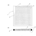
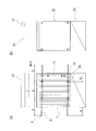
- FIG. 1 (a) and 1 (b) are cross-sectional views schematically showing an example of an embodiment of a separation membrane element constituting the element unit of the present invention, and FIG. 1 (a) is parallel to the membrane surface at the center of thickness.
- FIG. 1B is a cross-sectional view cut in the thickness direction.
- FIG. 2 is a cross-sectional view corresponding to FIG. 1 (a) showing an example of another embodiment of the separation membrane element constituting the element unit of the present invention.
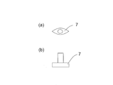
- 3 (a) and 3 (b) are schematic views showing an example of an embodiment of a water collection nozzle used in the present invention, FIG. 3 (a) is a plan view, and FIG. 3 (b) is a front view.
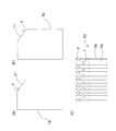
- FIGS. 4 (a) and 4 (b) are schematic diagrams showing an example of still another embodiment of the separation membrane element constituting the element unit of the present invention, and FIG. 4 (c) is shown in FIGS. 4 (a) and 4 (b). It is the schematic which looked at the embodiment of the element unit which arranged the described separation membrane element alternately from the top.
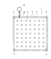
- FIG. 5 (a) is a schematic view showing an example of still another embodiment of the separation membrane element constituting the element unit of the present invention
- FIG. 5 (b) shows the separation membrane element described in FIG. 5 (a).
- FIG. 6 is a sectional view showing another example of the embodiment of the separation membrane element constituting the element unit of the present invention.
- FIGS. 7 (a) and 7 (b) are cross-sectional views showing another example of the embodiment of the end portion of the separation membrane element constituting the element unit of the present invention.
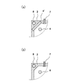
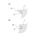
- FIGS. 8A and 8B are schematic cross-sectional views showing, in a partially enlarged manner, another example of the embodiment of the fixing portion using the shaft constituting the element unit of the present invention.
- FIG. 9 is a perspective view showing an example of the embodiment of the separation membrane module of the present invention.
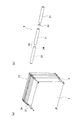
- FIG. 10A is a perspective view schematically showing an example of an embodiment of the element unit of the present invention
- FIG. 10B is a perspective view of an example of a shaft constituting the element unit seen from another direction. is there.
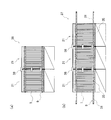
- FIG. 11A is a front view of the separation membrane module shown in FIG. 9, and FIG.
- FIG. 11B is a side view.
- 12 (a) and 12 (b) are front views showing an example of an embodiment of the separation membrane module unit of the present invention
- FIG. 12 (a) is a unit in which two separation membrane modules are connected
- FIG. 12 (b). Is a unit in which three separation membrane modules are connected.
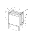
- FIG. 13 is a perspective view showing another example of the embodiment of the separation membrane module of the present invention.
- FIG. 14 is a perspective view showing an example of an embodiment of the element unit of the present invention.
- FIG. 15 is a partially enlarged perspective view showing an example of a housing groove guide portion constituting the separation membrane module of the present invention.
- FIG. 16 is a perspective view showing still another example of the embodiment of the separation membrane module of the present invention.
- the element unit has a plurality of separation membrane elements.
- the separation membrane element is an element having a flat membrane structure.
- a water collection portion is provided at a part of the peripheral edge of the membrane, and the water collection
- the peripheral part other than the part is sealed.
- a resin part is disposed on the permeation side surface region of the separation membrane inside the sealed peripheral edge, and a part of the separation membrane on both sides is adhered to the resin part.
- FIG. 1 (a) and 1 (b) are cross-sectional views illustrating an embodiment of a separation membrane element
- FIG. 1 (a) is a cross-sectional view in plan view cut in parallel with the membrane surface at the thickness center of the separation membrane composite
- FIG. 1B schematically illustrates a cross section in the thickness direction.
- the separation membrane element 1 has a sealing portion 2, a water collection portion 3, a dot-like resin portion 4, a water collection flow path 5, and a separation membrane 6.
- the separation membrane element 1 is composed of a separation membrane pair composed of two separation membranes 6 and 6.
- the separation membranes 6 and 6 are arranged such that the surfaces on the permeate side face each other and leave a predetermined gap.
- the periphery (peripheral part) of the gap is sealed to form the sealing part 2, and a part between the separation films 6 and 6 inside the peripheral part is connected by the resin part 4.
- the predetermined interval formed between the separation membranes 6 and 6 becomes a flow path through which the water that has passed through the membrane passes, that is, the water collection flow path 5, and the water that passes there is collected in the water collection section 3, from here It is taken out of the separation membrane element 1.
- the periphery (peripheral part) of the separation membrane element 1 is sealed by a method such as adhesive resin, heat welding, ultrasonic welding, etc., and constitutes the sealing part 2.
- a water collecting portion 3 is provided at a part of the membrane peripheral portion, and this water collecting portion 3 is not sealed.
- the sealing at the peripheral edge means that the supply water (treated water) outside the separation membrane element flows directly into the inside of the separation membrane element from the peripheral edge by adhesion, pressure bonding, welding, fusion, folding, or the like. (That is, to prevent the supply water from flowing in a route other than passing through the separation membrane). At the same time, the permeated water that has passed through the separation membrane is prevented from leaking outside the separation membrane element except for the water collection section 3.
- the separation membrane 6 forming a pair may be one in which the opposite edges of two independent separation membranes are sealed, or the opposite edge in one folded separation membrane is sealed. But you can.
- the configuration in which the resin part 4 bonds a part of both separation membranes means that, in the separation membrane pair, the resin part 4 has both the permeation side surface of one separation membrane 6 and the permeation side surface of the other separation membrane 6 opposite thereto. Refers to the structure that adheres to That is, in the separation membrane pair, one separation membrane is fixed to the other separation membrane via the resin portion.
- “inside” refers to the surface of the permeation side surface of the separation membrane 6 excluding the peripheral edge.
- the portion surrounded by the sealing portion corresponds to “inside”.
- the separation membrane 6 is not limited as long as it separates components in the fluid supplied to the surface of the separation membrane and obtains a permeated fluid that has permeated the separation membrane.
- a separation membrane a separation functional layer, a porous support layer, and a base material can be provided, for example.
- the resin component of the resin part 4 may be impregnated in the base material.
- resin is disposed on the base material on the permeation side of the separation membrane and heated from the surface of the separation functional layer of the separation membrane, the impregnation of the resin proceeds from the permeation side of the separation membrane toward the functional layer surface.
- the adhesion between the resin and the substrate becomes stronger. For this reason, when the manufactured separation membrane element 1 is washed, even if it is washed from the permeation side with a chemical solution, the separation membrane pair is hardly separated.
- the separation membrane element 1 by ensuring a predetermined gap on the permeation side of the separation membrane 6, the flow resistance of the permeated water that has permeated the separation membrane 6 can be reduced. Normally, if a member such as a spacer is not provided on the permeation side of the separation membrane 6 in the separation membrane element, the permeation sides of the separation membrane are in close contact with each other. To do.
- the separation membrane element 1 secures a gap between the separation membranes and reduces the flow resistance of the permeated water without arranging such a member such as a spacer.
- the gap on the permeate side between the separation membranes 6 and 6 is preferably in the range of 50 ⁇ m to 5000 ⁇ m.
- the gap between the separation membranes is 5000 ⁇ m or less, the impact of bubbles colliding with the membrane surface during the aeration operation during the water treatment operation is alleviated, so that the membrane is prevented from being damaged.
- the separation membrane has a gap of 50 ⁇ m or more, a wide space is secured between the membrane surfaces on the permeate side facing each other, so that the flow resistance of the permeate is reduced, and as a result, the amount of permeate is increased.
- the gap between the separation membranes is more preferably in the range of 500 ⁇ m or more and 3000 ⁇ m or less.
- the separation membrane and the flow path material are not fixed, so cleaning from the permeation side with a chemical solution permeates the separation membrane. Due to the pressure applied from the side, the bag formed of the separation membrane may swell and the separation membrane 6 may be damaged. By attaching the resin part 4 between the separation membranes 6 and 6 and bonding them, it is possible to prevent such breakage and to clean the permeate side with a chemical solution.
- the separation membrane may be peeled off by washing from the permeation side with a chemical solution. . Therefore, the area ratio of the inner resin part is preferably in the range of 1% to 70%. More preferably, it is the range of 10% or more and 50% or less.
- the shape of the resin portion 4 is not particularly limited, and the shape projected on the separation membrane is a dot shape such as a circle, a polygon, or an indeterminate shape, or a line shape such as a straight line, a curve, a wavy line, a zigzag, or a lattice shape. Can be formed. Further, the arrangement of the dot-shaped resin is not particularly limited, such as a lattice dot shape or a staggered array shape. By adjusting the shape and arrangement of the inner resin portion, the separation membrane element can be designed so as to satisfy the required separation characteristics and permeation performance conditions.
- the projected image of the resin part onto the separation membrane 6 is preferably discontinuous.
- two or more resin parts are arranged on one separation membrane at intervals in the planar direction of the separation membrane. More specifically, it is preferable that 1 or more, 5 or more, or 10 or more resin parts are provided per 5 cm square in the inner part of the permeation side surface of the separation membrane 6. Moreover, it is preferable that 100 or less, 50 or less, or 30 or less resin parts are provided per 5 cm square.
- polyolefin, copolymer polyolefin, etc. such as ethylene vinyl acetate copolymer resin, polyethylene, a polypropylene
- Polymers such as urethane resins and epoxy resins can also be selected.
- a thermoplastic polymer is easy to mold, the shape of the resin can be made uniform. If the thermoplastic polymer has a high melting point, the separation functional layer may be dissolved when the resin is adhered to the separation membrane. If the melting temperature is too low, the inside of the separation membrane may be peeled off during operation. Therefore, the resin is preferably a thermoplastic polymer having a melting point in the range of 80 ° C to 200 ° C.
- the method for adhering the sealing portion 2 and the resin portion 4 to the separation membrane 6 is not particularly limited, but the required separation characteristics and permeation performance conditions can be satisfied by changing the processing temperature and the type of resin to be selected. Thus, the shape of the resin can be adjusted freely.
- the same resin may be applied to the sealing part 2 and the resin part 4, or different resins may be applied, and the sealing part 2 does not use a resin and welds the separation membranes directly. May be.
- the separation membrane 6 is bonded by the above-described method, so that the adhesive bears the effect of the bonding interlining and gives the separation membrane 6 appropriate flexibility and rigidity. For this reason, it is also necessary to select the interval, shape, and material of the resin parts from the viewpoint of the flexibility and rigidity of the separation membrane 6 together with the bonding condition.
- the separation membrane is a flat membrane-like separation membrane, and preferably has a separation functional layer formed on a non-woven base material.
- the thickness of the separation functional layer of the separation membrane is too thin, defects such as cracks may occur and the filtration performance may deteriorate. If it is too thick, the water permeability may decrease. 1 ⁇ m to 500 ⁇ m), preferably 0.05 to 0.2 mm (50 ⁇ m to 200 ⁇ m).
- a crosslinked polymer is preferably used in terms of pore size control and durability, and polyfunctional amine and polyfunctional acid halide are polycondensed on the porous support layer in terms of component separation performance.
- a membrane in which a separation functional layer, an organic / inorganic hybrid functional layer, and the like are laminated can be suitably used.
- a porous support layer such as a cellulose membrane, a polyvinylidene fluoride membrane, a polyethersulfone membrane, or a polysulfone membrane, which has both a separation function and a support function, can also be used. That is, the separation functional layer and the porous support layer may be realized as a single layer.
- the separation membrane is preferably composed of a base material and a separation functional layer, and in particular, a separation membrane formed with a separation functional layer made of a polyvinylidene fluoride resin may be used.
- a layer in which the resin constituting the separation functional layer and the base material are mixed is interposed between the base material and the separation functional layer.
- the separation functional layer may be present on one side with respect to the base material, or may be present on both sides.
- the separation functional layer may have a symmetric structure or an asymmetric structure with respect to the base material. Further, when the separation functional layer is present on both sides with respect to the substrate, the separation functional layers on both sides may be continuous through the substrate or may be discontinuous. .
- the base material has a function of supporting the separation functional layer and giving strength to the separation membrane.
- the material constituting the base material is not particularly limited, such as an organic base material or an inorganic base material, but an organic base material is preferable from the viewpoint of easy weight reduction.
- the organic substrate include woven and knitted fabrics and nonwoven fabrics made of organic fibers such as cellulose fibers, cellulose triacetate fibers, polyester fibers, polypropylene fibers, and polyethylene fibers. Among these, a nonwoven fabric whose density is relatively easy to control is particularly preferable.
- the separation membrane 6 can be applied to any of reverse osmosis membranes, nanofiltration membranes, ultrafiltration membranes, and microfiltration membranes. Further, one or more appropriate membranes may be selected and combined depending on the size of the substance to be separated, but ultrafiltration membranes and microfiltration membranes are particularly preferable for treating sewage wastewater.
- the water that has passed through the separation membrane 6 is collected in the water collection section 3 through the water collection flow path 5 and taken out of the system of the separation membrane element via the water collection nozzle 7 attached to the water collection section 3. It is. In order to take out permeated water easily and reliably from the water collecting part, it is preferable to arrange a hollow water collecting nozzle in the water collecting part.
- FIG. 2 shows the separation membrane element 1 and the water collection nozzle 7 side by side. Moreover, in FIG. 3, the top view (a) and front view (b) of the water collection nozzle 7 are shown.
- a water collecting part 3 is provided in a part of the sealing part 2 at the periphery of the membrane, and a water collecting nozzle 7 is disposed in the water collecting part 3.
- the water collecting portion 3 is not sealed, and is sealed after the water collecting nozzle 7 is attached.
- the water collection nozzle 7 communicates the water collection flow path 5 and the outside of the separation membrane element 1.
- the width necessary for installing the water collecting nozzle 7 may be determined comprehensively based on the size of the water collecting nozzle 7 to be attached, the size of the separation membrane element 1 and the like.
- the cylindrical shape of the water collecting nozzle 7 is used.
- the diameter of the part is about 0.3 cm to 3 cm.
- the structure of the water collection nozzle 7 is not particularly limited as long as the purpose of extracting the permeated water from the separation membrane element 1 is achieved.
- a resin tube can be used.
- the water collection nozzle 7 is composed of upper and lower hollow members.
- the lower part of the water collection nozzle 7 is arranged so that the two curved surfaces are hollow, the lower part is opened and the upper part is closed with a substantially flat surface, and an opening is provided at the approximate center of the upper surface.
- a cylindrical portion (upper hollow member) whose cross-sectional shape is circular or elliptical is connected.
- a sealing method a method by heat welding, a method using an adhesive, and the like can be considered, but the sealing method is not particularly limited. In order to make sealing more reliable, a method in which heat welding and an adhesive are used in combination is also conceivable.
- the shape of the attachment portion is not particularly limited, but an appropriate one may be selected from the size of the separation membrane element 1 and the size and shape of the water collection nozzle 7.
- the separation membrane element is an element without the support plate, the thickness of the entire element can be reduced. For this reason, it is possible to increase the membrane area (filling rate of the separation membrane) per installation area as an element unit.
- a water collection nozzle 7 is attached to the separation membrane element 1. For this reason, the problem is how to arrange the water collection nozzles rather than the membrane portion and increase the filling rate of the separation membrane element 1. Then, the element unit of this invention is arrange
- FIG. 4 (c) shows an embodiment of the element unit as seen from above, in which a plurality of separation membrane elements 1a and 1b are alternately arranged.
- 4A to 4C show an example, and the structure is not limited to this structure as long as the water collection nozzle 7 can be disposed so as not to interfere.
- the separation membrane elements 1a and 1b described in FIGS. 4 (a) and 4 (b) take one corner of a rectangular flat membrane-like separation membrane, have a shape having an inclined side 11, and a water collecting portion on the inclined side.
- a water collecting nozzle 7 is arranged.
- by providing the inclined side 11 and arranging the water collecting nozzle 7 on the inclined side 11 in this way it is easy to position the mounting position of the water collecting nozzle.
- a water collection pipe is installed on the side of the membrane element and this water collection pipe and each water collection nozzle are connected by a tube, etc., make sure that the water collection nozzle is not subjected to excessive force.
- the adhesion is prevented from being peeled off or broken.
- Fig. 5 (a) shows an example of a separation membrane element according to this embodiment
- Fig. 5 (b) shows an example of an embodiment of an element unit.
- through holes 8 are arranged at four locations near the end (corner) of the separation membrane element 1.
- An appropriate number of through holes may be formed depending on the size of the element.
- the separation membrane is substantially rectangular, it is preferable to provide through holes at the outer four corners in the surface direction of the separation membrane.
- the through hole is formed by hitting a grommet, the periphery of the through hole is reinforced, which is preferable in terms of durability.
- the separation membrane elements having through holes are arranged and arranged so that the water collecting nozzles 7 do not overlap each other. Can be made into an element unit. By adopting such a structure, it is possible to greatly reduce the members constituting the element unit.
- the separation membrane element, element unit, and separation membrane module have moderate rigidity and flexibility that allows aeration energy to escape, and have excellent durability against aeration from the bottom when used in MBR.
- FIG. 6 is a cross-sectional view showing an example of another embodiment of the separation membrane element constituting the element unit of the present invention cut by a plane at the center in the thickness direction of the separation membrane element.
- a water collecting pipe 27 and a tube 26 are described.
- a water collection pipe 27 is connected to the water collection nozzle 7 via a tube 26.
- a suction pump (not shown) is connected to the downstream side of the water collection pipe 27, and a negative pressure is applied to the inside of the separation membrane element 1 to take out permeated water.
- the separation membrane element 1 is mainly composed of two flat membrane-like separation membranes 6 arranged with a separation membrane pair arranged so that the surfaces on the permeate side face each other. It has a sealed bag-like structure.
- the separation membrane element 1 has a suspension part represented by the through hole 8 at the outer end in the surface direction of the separation membrane. The edge of the through-hole 8 is sealed, and is configured to block the outside and the inside of the separation membrane element.
- the through hole 8 may be surrounded by the sealing portion 2 and / or the resin portion 4 '.
- the cross-sectional area in the edge part of the sealing part 2 may be taken large, and the through-hole 8 may be formed in the inside.
- the number of through holes 8 is four through holes in FIG. 6, but is not limited to this example, and can be set as appropriate depending on the size and shape of the elements.
- the position of the through hole 8 is not particularly limited. In terms of durability, the through hole 8 is preferably reinforced around the hole by hitting a stopper such as eyelet. Any material such as stainless steel, aluminum, polycarbonate resin, or ABS resin can be used as the material of the fastener.
- an upper support structure (FIG. 8 (a)) or notch structure (FIG. 8 (b)) may be used.
- the upper support structure of the suspension portion shown in FIG. 8A is configured so that protrusions 51 are formed at the upper portions of the left and right ends of the separation membrane element 1 so that the protrusions 51 are supported on the upper side of the shaft 9.
- the notch structure of the suspension part is formed with a notch part 52 that accommodates the shaft 9 at both left and right ends of the separation membrane element 1, and the shaft 9 passes through the notch part 52. It is a structure to be fixed.
- the shape, position, and number of the protrusions 51 and the notches 52 can be determined as appropriate.
- FIG. 9 is a perspective view showing an example of the embodiment of the separation membrane module of the present invention.
- the separation membrane module 21 includes an element block 22, an aeration block 23, and a water collection pipe 27.
- the element block 22 accommodates the element unit 10 described above inside the housing 32.
- the element unit 10 is configured by arranging a plurality of separation membrane elements 1 in parallel so that the shafts 9 are respectively passed through the through holes 8 of the separation membrane element 1.
- An aeration block 23 is disposed below the element block 22.
- the aeration block 23 includes an air diffuser (not shown) connected to a blower (not shown). Air is ejected from the lower aeration block 23 toward the element block 22 of the separation membrane module 21 submerged in the water to be treated in the activated sludge tank.
- a clearance holding member 28 is provided between the adjacent separation membrane elements 1, in order to secure a flow path of water to be treated and air.
- the clearance holding member 28 is not particularly limited, but a polyurethane washer or collar or a rubber washer or collar typified by nitrile rubber or silicon rubber is preferable from the viewpoint of durability and shock absorption. Used for.
- the separation membrane element and the separation membrane module have an appropriate rigidity and a flexibility to release the energy of aeration, and have excellent durability against aeration from the lower aeration block 23. Will show gender.
- the shaft 9 that has passed through the through holes 8 at the end portions (four corners in the example of FIG. 9) of the separation membrane element 1 is connected and fixed to the housing 32 by the shaft holding portion 33.
- the shaft 9 is slidable in a direction substantially parallel to the entire length of the separation membrane module (direction perpendicular to the flat membrane of the membrane element).
- the shaft 9 and the housing 32 are connected by installing the shaft holding portion 33 in the housing 32 and passing the shaft 9 through the shaft holding portion 33. Further, the shaft 9 can be slid by operating the set screw mechanism of the shaft holding portion 33.
- the connection between the shaft 9 and the housing 32 is not particularly limited, and a hole for passing the shaft is provided in the frame of the housing 32 and a C-shaped or E-shaped retaining ring is used.
- the format and method may be arbitrary.
- the material of the housing frame and shaft holding part can be arbitrarily selected from various metals such as stainless steel and aluminum, various thermoplastic resins such as PVC resin and ABS resin, and various thermosetting resins such as polyurethane resin and epoxy resin. However, a stainless material having high corrosion resistance and rigidity is preferably used.
- the shaft 9 is preferably constructed by connecting a plurality of unit shafts 31 together.
- a shaft joint 34 that connects adjacent unit shafts 31 can be used.
- FIG. 10B a method of connecting and fixing unit shafts 31 having stepped ends at both ends by a shaft joint 34 typified by a set collar can be used conveniently and suitably.
- the outer diameter of the unit shaft 31 and the outer diameter of the set collar are substantially the same.
- the connected shaft 9 is passed through the through-hole of the separation membrane element 1 to smoothly Can be slid.
- other methods such as a key set type and a pinning type can be arbitrarily selected.
- the material of the shaft 9 and the unit shaft 31 can be arbitrarily selected from various metals such as stainless steel and aluminum, various thermoplastic resins such as PVC resin and ABS resin, and various thermosetting resins such as polyurethane resin and epoxy resin.
- a stainless material having high corrosion resistance and rigidity is preferably used.
- either a solid shaft or a hollow shaft may be used, and the shaft shape is not limited to a round shape, and may be an arbitrary shape such as an ellipse or a substantially square shape.
- the unit shaft is not limited to a rigid rod such as a shaft or pipe, but may be a flexible rod such as a wire or string as long as the membrane element can be suspended. In this case, it is desirable to provide a joint portion at each end so that the flexible rod can be connected.
- the shaft holding portion By releasing the fixed portion 33, sliding the connecting portion 35 of the shaft 9 around the damaged element, and separating the connecting portion 35 and the unit shaft 31, the failed membrane element can be easily extracted.
- the space after extraction can be reloaded with a new or repaired membrane element, or can be loaded with a spacer represented by shims, washers, and the like. That is, it is not necessary to disassemble the entire element block, and any membrane element can be easily maintained.
- the length and number of unit shafts 31 will be described with reference to FIG.
- the length of the unit shaft 31 is S
- the number of unit shafts related to one separation membrane module is N
- the total length of the separation membrane module is L
- S ⁇ It is preferably defined by L / (N-1).
- the lengths S of the plurality of unit shafts 31 may be the same as or different from each other as long as the above formula is satisfied. For example, in FIG. 11, when the module total length L is 100 cm and the number N of unit shafts is 3, the unit shaft length S needs to be at least 50 cm.
- the sliding margin A of the shaft 9 relative to the total length L of the separation membrane module is from the distance B to the failed separation membrane element 1x that is to be extracted from the shaft coupling portion 35. It means big. If the slide allowance A is smaller than the distance B, the shaft 9 slides down in the module and cannot function.
- the unit shaft length S is a length in a direction substantially parallel to the separation membrane module full length L
- the separation membrane module full length L is a length in a direction substantially parallel to the longitudinal direction of the water collecting pipe. is there.
- both end portions of the shaft 9 can be configured such that adjacent separation membrane modules 21 can be connected to each other.
- the configuration in which the adjacent shafts 9 can be connected can be the same as the method of connecting the unit shafts 31 described above.
- FIG. 12A shows a separation membrane module unit 36 when two separation membrane modules 21 constituted by the shaft 9 are connected
- FIG. 12B shows three separation membrane modules 21 connected.
- the separation membrane module unit 37 in the case is shown.
- S the number of unit shafts N
- the separation membrane module unit can be configured without lowering the filling rate of the membrane element.
- the connecting portion 35 of the shaft 9 is slid around the damaged element.
- the separation membrane element can be easily extracted.
- the space after extraction can be reloaded with a new or repaired membrane element, or can be loaded with a spacer represented by shims, washers, and the like. That is, it is not necessary to disassemble the entire separation membrane module unit, and maintenance of any membrane element can be easily performed.
- the method of attaching and detaching the separation membrane element from the separation membrane module of the present invention slides (moves) the connecting portion of the shaft to the vicinity of the separation membrane element to be attached and detached, separates the connecting portion, and from the separated end portion,
- the separation membrane element can be individually attached and detached by inserting and removing the suspension portion of the separation membrane element. This facilitates maintenance of the separation membrane module, that is, replacement or removal of the failed membrane element.
- the separation membrane module units 36 and 37 shown in FIGS. 12 (a) and 12 (b) are immersed in the immersion tank, heavy machinery work is required.
- the connection member 38 since the joint strength is low only by the shaft connection, the casings 32 may be joined to each other using the connection member 38.
- the joining method of the connecting member 38 and the casing may be arbitrary, but a bolt and nut method using a stainless plate, an angle, or the like is preferable.
- FIG. 13 is a perspective view showing another example of the embodiment of the separation membrane module of the present invention.
- the separation membrane module 121 has substantially the same configuration as the separation membrane module 21 of FIG.
- the separation membrane module 121 includes a housing 132 that can accommodate a plurality of element units 10.
- the separation membrane module 121 includes an element block 122, an aeration block 23, and a water collection pipe (not shown).
- the element block 122 is configured by an element unit 10 and a housing 132 that accommodates the element unit 10 in a removable manner.
- An aeration block 23 is disposed below the element block 122.
- the aeration block 23 includes an air diffuser (not shown) connected to a blower (not shown). Air is ejected from the lower aeration block 23 toward the element block 122 of the separation membrane module 121 submerged in the water to be treated in the activated sludge tank.
- FIG. 14 is a perspective view showing an example of an embodiment of the element unit 10 applied to the separation membrane module 121 of FIG.
- the element unit 10 is configured by arranging a plurality of separation membrane elements 1 in parallel so that shafts pass through the through holes of the separation membrane element 1 described above.
- a clearance holding member 28 (FIG. 9) is provided between adjacent separation membrane elements 1 in order to secure a flow path of water to be treated and air.
- the water collection nozzle 7 is arranged on the side surface of the separation membrane element 1 so as not to interfere with the position of the through hole 8. “Do not interfere” means that the water collection nozzle 7 is provided so as to be separated from the through hole 8, that is, provided at a different position. While the water collection nozzle 7 communicates with the water collection flow path 5, the through hole 8 is isolated from the water collection flow path 5 by the sealing portion 2 or the resin portion 4 ′ to prevent leakage of permeated water. It is preferable (FIGS. 7A and 7B). Therefore, the water collection nozzle 7 and the through hole 8 are preferably provided so as to be separated from each other.
- Side plates 41 are provided at both ends of the element unit 10 in consideration of handling properties when accommodated in the housing 132. Further, a fixing member 42 for fixing each of these parts is provided on the shaft 9 or the side plate 41 part.
- the number of the separation membrane elements 1 constituting the element unit 10 can be arbitrarily set to 10 to 150, but 20 to 50 is preferable in consideration of handling property when being taken in and out of the housing 132.
- the membrane element shape is not particularly limited, but a substantially rectangular shape is preferably used.
- the suspension part of the separation membrane element 1 and the clearance holding member 28 are as described above.
- the thickness of the side plate 41 is not particularly limited, but may be 2 to 10 mm, and a range of 2 to 5 mm is preferably used in consideration of increasing the filling rate of the separation membrane element 1.
- the shape of the side plate 41 may be arbitrary, but a flat bar (flat steel) that does not have a projection or the like that may damage the membrane surface when adjacent membrane elements are swung and contacted by aeration air is preferable.
- the side plate 41 is provided with a handle (not shown).
- the shape of the handle may be arbitrary, and an arbitrary shape such as an ellipse or a substantially square shape may be cut out from the side plate, or a handle made of a member such as metal may be separately installed on the side plate 41.
- the material of the side plate 41 and the handle can be arbitrarily selected from various metals such as stainless steel and aluminum, various thermoplastic resins such as PP resin, PVC resin and ABS resin, and various thermosetting resins such as polyurethane resin and epoxy resin.
- PP resin is preferably used from the viewpoint of corrosion resistance, weight, and wear resistance.
- the end of the shaft 9 has a screw structure, and both ends are fastened and fixed by a fixing member 42 such as a fastening nut via a plurality of separation membrane elements 1 and side plates 41.
- a fixing member 42 such as a fastening nut via a plurality of separation membrane elements 1 and side plates 41.
- the end portion of the shaft 9 must have a screw structure, but it may have a full screw structure represented by a dimension bolt or the like, or a structure in which only the shaft end portion is threaded.
- the fixing member 42 such as a nut may be directly joined to the shaft 9 or the side plate 41 or may be separated.
- the housing 132 has an opening 43 through which the element unit 10 can be taken in and out, on at least one of the upper surface and the side surface.
- each element unit 10 can be detached from the housing 132, so that maintenance and replacement or removal of the membrane element can be facilitated.
- the separation membrane element 1 mainly constituting the element unit 10 has a structure without a support plate, its weight is as light as about 100 to 500 g, and the unit is also about 5 to 25 kg (dry weight / number of membrane elements). 50). Therefore, the element unit can be easily taken in and out without using a heavy machine or the like, which is a great merit at the time of maintenance and replacement or removal of the membrane element.
- the distance of the gap between the element unit 10 and the opening 43 is not particularly limited as long as the distance between the element unit 10 and the opening 43 can be taken in and out, but can be 2 to 10 mm, for example. In consideration of increasing the packing rate of the separation membrane element 1, 2 to 5 mm is more preferable.
- the housing 132 is provided with a groove guide 44 (notch guide) for allowing the end portion of the shaft 9 or the fixing member 42 to pass when the element unit 10 is inserted and removed. By doing so, positioning is performed when the element unit 10 is suspended, and handling is improved. Furthermore, since the distance between the element unit 10 and the opening 43 can be reduced, the filling rate of the separation membrane element 1 can be further increased.
- the housing 132 has a unit suspension that can suspend the element unit 10 using the shaft 9. Specifically, as shown in FIG. 13, a recess 45 is provided on the surface of the frame of the housing 132 orthogonal to the shaft 9, and the shaft 9 fitted in the recess 45 is pressed and held from above by a shaft pressing tool (not shown). Good.
- the configuration of the unit suspension is not limited to this, and a gripping method according to another suspension configuration as shown in FIG. 8 can be arbitrarily selected.
- the materials of the main structural members constituting the casing 132 are various metals such as stainless steel and aluminum, various thermoplastic resins such as PP resin, PVC resin and ABS resin, polyurethane resin and epoxy resin, etc. These various thermosetting resins can be arbitrarily selected.
- FIG. 16 is a perspective view showing another example of the embodiment of the separation membrane module of the present invention.
- the housing 232 has a structure in which a plurality of element units 10 can be stacked vertically or horizontally. Each element unit is arranged at a position where it can be extracted in a substantially horizontal direction or a substantially vertical direction through a plurality of openings 43.
- FIG. 16 shows an example in which three parallel element units are arranged in two stages in the vertical direction.
- the present invention is not particularly limited to this, and is arbitrarily set depending on the size of the bath to be immersed, the required processing capacity, and the like. It is possible. In particular, when loading element units in multiple stages in the vertical direction, it is possible to save space and save energy by significantly increasing the membrane area per unit area occupied by aeration air diffused from below the element unit. Can also be achieved.
- the element block 22 is arranged such that a single element or a plurality of element units 10 are individually detachable through openings 43 provided in a parallel and vertical multi-stage provided in the housing 32. Constitute. For this reason, the element unit 10 can be easily and individually inserted and removed without complicated separation work in the element block 22, so that workability at the time of maintenance and membrane replacement can be improved. Time can be greatly reduced. Further, since the separation membrane element 1 has a structure without a support plate, even when unitized, it can be significantly reduced in weight compared to a conventional separation membrane element with a support plate, and the housing 32 Can be simplified, and the manufacturing cost as a module can be greatly reduced.
- the separation membrane element having the configuration of the present invention has the form schematically shown in FIG. 1, and the resin part is formed in a cylindrical shape having a diameter of about 3.0 mm and a height of about 2.5 mm.
- the periphery of the separation membrane was sealed with a sealing portion having a width of about 20 mm, and a water collecting portion having a width of about 35 mm was formed on a part of the periphery so as to be a combination of positions that did not overlap between adjacent separation membrane elements. .
- a water collection nozzle made of polyethylene resin having the shape of FIG. 3 was inserted into this water collection portion, and then sealed.
- a through hole (diameter of about 20 mm) is formed at the end of the separation membrane element, and a through rod is passed through the through hole while arranging adjacent water collecting nozzles so as not to overlap.
- the separation membrane element of the present invention was half the thickness of the element and the weight of the element was 1 ⁇ 4 that of the conventional separation membrane element.
- the weight of the separation membrane module as a whole was 1 ⁇ 4 or less.
- the weight can be reduced to about 1/5.
- the membrane filling rate of the separation membrane module of the present invention was 1.3 times that of the conventional separation membrane module. This is because the separation membrane element is thinned and the water collecting nozzle is disposed so as not to interfere.
- the support plate-less element successfully improved the energy of aeration from the results of operation of the MBR prototype module in which the separation membrane element (support plate-less element) of the present invention was actually arranged for several months.
- the separation membrane element was not damaged.
Landscapes
- Chemical & Material Sciences (AREA)
- Chemical Kinetics & Catalysis (AREA)
- Engineering & Computer Science (AREA)
- Water Supply & Treatment (AREA)
- Life Sciences & Earth Sciences (AREA)
- Hydrology & Water Resources (AREA)
- Environmental & Geological Engineering (AREA)
- Organic Chemistry (AREA)
- Biodiversity & Conservation Biology (AREA)
- Microbiology (AREA)
- Separation Using Semi-Permeable Membranes (AREA)
Abstract
Description
特許文献4では、平膜で形成された袋である複数の膜エレメントを備える膜モジュールが記載されている。複数の膜エレメントは、膜エレメントに取り付けられた輪によって、直方体形状の枠に、互いに並行になるように並べられている。枠は、沈降槽の壁等に固定される。各膜エレメントには、透過液の流出孔として分離膜および流路材を貫通する孔が設けられている。隣り合う膜エレメント同士は、それぞれの流出孔に接続する筒状の結合部材によって連結されている。
前記シャフトに前記分離膜エレメントを懸架する懸架部と、
前記集水流路と前記分離膜エレメントの外部とを連通する集水ノズルと、
を備えるエレメントユニット。
(2) 前記分離膜エレメントは、前記分離膜対の互いに対向する透過側の面の両方に接着する樹脂部を備え、
該樹脂部は、ドット状、線状、または格子状である
上記(1)に記載のエレメントユニット。
(3) 前記シャフトは、複数の単位シャフトを備える
上記(1)または(2)に記載のエレメントユニット。
(4) 前記シャフトは、隣接する前記単位シャフト同士を接続するシャフトジョイントをさらに備える
上記(3)に記載のエレメントユニット。
(5) 前記シャフトは前記懸架部を貫通するように設けられており、
前記分離膜エレメントは、前記シャフトの前記懸架部に対する抜き差しにより、前記シャフトに対して着脱可能である
上記(1)~(4)のいずれかに記載のエレメントユニット。
(6) 前記分離膜は平膜であり、
前記分離膜対において、前記集水流路よりも前記分離膜の面方向において外側に、前記シャフトが貫通可能な孔が設けられており、
前記上記孔が前記懸架部として機能する
上記(1)~(5)のいずれかに記載のエレメントユニット。
(7) 前記分離膜が略四角形であり、
前記貫通孔が前記分離膜対の四隅に設けられている
上記(6)に記載のエレメントユニット。
(8) 上記(1)~(7)のいずれかに記載のエレメントユニットと、
前記エレメントユニットを出し入れ可能に収容する筐体と、
前記筐体の下方に配置され、前記エレメントユニットにエアを供給するエアレーションブロックと、
を備える分離膜モジュール。
(9) 前記筐体は、上面または側面の少なくとも一方に、前記エレメントユニットを出し入れ可能な開口部を有する
上記(8)に記載の分離膜モジュール。
(10) 前記懸架部を貫通するように設けられた前記シャフトを備える上記(8)または(9)に記載の分離膜モジュールにおいて、前記分離膜エレメントを着脱する方法であって、
前記シャフトをスライドさせて前記懸架部から抜き差しすることにより、前記分離膜エレメントを前記分離膜モジュールから着脱することを特徴とする分離膜エレメントの着脱方法。
本発明において、エレメントユニットは、複数の分離膜エレメントを有する。その分離膜エレメントは、平膜構造をしたエレメントであって、透過側の面同士が対向するように分離膜を貼りあわせるに際し、膜の周縁部の一部に集水部を設け、かつ集水部以外の周縁部を封止している。封止した周縁部よりも内側の分離膜の透過側表面領域に、樹脂部を配置し、この樹脂部で両側の分離膜の一部を接着させた構造を有する。
図9において、分離膜モジュール21は、エレメントブロック22、エアレーションブロック23および集水管27により構成される。エレメントブロック22は、筐体32の内側に、上述したエレメントユニット10を収容する。エレメントユニット10は、分離膜エレメント1の貫通孔8にそれぞれシャフト9を通すようにして、分離膜エレメント1を複数平行に並べることで構成されている。このエレメントブロック22の下方にはエアレーションブロック23が配設されている。エアレーションブロック23は、ブロワ(図示せず)に連結されている散気装置(図示せず)からなる。活性汚泥槽内の被処理水中に沈められた分離膜モジュール21のエレメントブロック22に向けて下方のエアレーションブロック23から空気が噴出される。
図13において、分離膜モジュール121は、図9の分離膜モジュール21とほぼ同様の構成を有する。ただし、分離膜モジュール121は、複数のエレメントユニット10を収容できる筐体132を備える。分離膜モジュール121は、エレメントブロック122、エアレーションブロック23および集水管(図示せず)により構成される。エレメントブロック122は、エレメントユニット10およびエレメントユニット10を出し入れ可能に収容する筐体132により構成される。このエレメントブロック122の下方にはエアレーションブロック23が配設されている。エアレーションブロック23はブロワ(図示せず)に連結された散気装置(図示せず)から構成される。活性汚泥槽内の被処理水中に沈められた分離膜モジュール121のエレメントブロック122に向けて下方のエアレーションブロック23から空気が噴出される。
筐体232は、エレメントユニット10を鉛直または水平方向に複数積載できる構造である。各エレメントユニットは複数の開口部43を介して略水平方向または略鉛直方向に抜き出し可能な位置に配置されている。図16では、3基の並列したエレメントユニットを鉛直方向に2段配置した例を示したが、特にこれに限定されず、浸漬する槽のサイズ、要求される処理能力、等々により任意に設定することが可能である。特に、鉛直方向に多段にエレメントユニットを積載する際には、省スペース化が図れるとともに、エレメントユニット下方から散気される曝気エアの占める単位面積当たりの膜面積を大幅に上げることができるため省エネルギー化も図れる。

1x 故障した分離膜エレメント
2 封止部
3 集水部
4 樹脂部
5 集水流路
6 分離膜
7 集水ノズル
8 貫通孔
9 シャフト
10 エレメントユニット
11 傾斜辺
21 分離膜モジュール
22 エレメントブロック
23 エアレーションブロック
26 チューブ
27 集水管
28 クリアランス保持部材
31 単位シャフト
32 筐体
33 シャフト保持部
34 シャフトジョイント
35 シャフト連結部
36 膜モジュールユニット
37 膜モジュールユニット
38 連結部材
L 膜のジュール全長
S 単位シャフト長さ
A スライド代
B シャフト連結部から抜き取りたい膜エレメントまでの距離
41 側板
42 固定部材
43 開口部
44 溝ガイド
45 凹部
51 突出部
52 切り欠き部
121 分離膜モジュール
122 エレメントブロック
132 筐体
222 エレメントブロック
232 筐体
Claims (10)
- シャフトと、
透過側の面が互いに対向するように配置された2枚の分離膜と前記分離膜間に設けられた集水流路とを有する分離膜対、および前記分離膜の周縁部において分離膜間を封止する封止部を含む複数の分離膜エレメントと、
前記シャフトに前記分離膜エレメントを懸架する懸架部と、
前記集水流路と前記分離膜エレメントの外部とを連通する集水ノズルと、
を備えるエレメントユニット。 - 前記分離膜エレメントは、前記分離膜対の互いに対向する透過側の面の両方に接着する樹脂部を備え、
該樹脂部は、ドット状、線状、または格子状である
請求項1に記載のエレメントユニット。 - 前記シャフトは、複数の単位シャフトを備える
請求項1または2に記載のエレメントユニット。 - 前記シャフトは、隣接する前記単位シャフト同士を接続するシャフトジョイントをさらに備える
請求項3に記載のエレメントユニット。 - 前記シャフトは前記懸架部を貫通するように設けられており、
前記分離膜エレメントは、前記シャフトの前記懸架部に対する抜き差しにより、前記シャフトに対して着脱可能である
請求項1~4のいずれかに記載のエレメントユニット。 - 前記分離膜は平膜であり、
前記分離膜対において、前記集水流路よりも前記分離膜の面方向において外側に、前記シャフトが貫通可能な孔が設けられており、
前記孔が前記懸架部として機能する
請求項1~5のいずれかに記載のエレメントユニット。 - 前記分離膜が略四角形であり、
前記貫通孔が前記分離膜対の四隅に設けられている
請求項6に記載のエレメントユニット。 - 請求項1~7のいずれかに記載のエレメントユニットと、
前記エレメントユニットを出し入れ可能に収容する筐体と、
前記筐体の下方に配置され、前記エレメントユニットにエアを供給するエアレーションブロックと、
を備える分離膜モジュール。 - 前記筐体は、上面または側面の少なくとも一方に、前記エレメントユニットを出し入れ可能な開口部を有する
請求項8に記載の分離膜モジュール。 - 前記懸架部を貫通するように設けられた前記シャフトを備える請求項8または9に記載の分離膜モジュールにおいて、前記分離膜エレメントを着脱する方法であって、
前記シャフトをスライドさせて前記懸架部から抜き差しすることにより、前記分離膜エレメントを前記分離膜モジュールから着脱することを特徴とする分離膜エレメントの着脱方法。
Priority Applications (6)
| Application Number | Priority Date | Filing Date | Title |
|---|---|---|---|
| CN201380036756.5A CN104411643B (zh) | 2012-07-10 | 2013-07-08 | 元件单元、分离膜模块、分离膜元件的装卸方法 |
| KR1020157002175A KR102054032B1 (ko) | 2012-07-10 | 2013-07-08 | 엘리먼트 유닛, 분리막 모듈, 분리막 엘리먼트의 착탈 방법 |
| JP2014524796A JP6164216B2 (ja) | 2012-07-10 | 2013-07-08 | エレメントユニット、分離膜モジュール、分離膜エレメントの着脱方法 |
| US14/411,434 US20150329381A1 (en) | 2012-07-10 | 2013-07-08 | Element unit, separation membrane module, attaching and detaching method for separation membrane element (as amended) |
| DK13816408.2T DK2873650T3 (da) | 2012-07-10 | 2013-07-08 | Element-enhed, skillemembranmodul og fremgangsmåde til forbindelse/afbrydelse af skillemembranen |
| EP13816408.2A EP2873650B1 (en) | 2012-07-10 | 2013-07-08 | Element unit, separation membrane module, and method for connecting/disconnecting separation membrane element |
Applications Claiming Priority (4)
| Application Number | Priority Date | Filing Date | Title |
|---|---|---|---|
| JP2012154336 | 2012-07-10 | ||
| JP2012-154336 | 2012-07-10 | ||
| JP2012167617 | 2012-07-27 | ||
| JP2012-167617 | 2012-07-27 |
Publications (1)
| Publication Number | Publication Date |
|---|---|
| WO2014010554A1 true WO2014010554A1 (ja) | 2014-01-16 |
Family
ID=49916008
Family Applications (1)
| Application Number | Title | Priority Date | Filing Date |
|---|---|---|---|
| PCT/JP2013/068639 Ceased WO2014010554A1 (ja) | 2012-07-10 | 2013-07-08 | エレメントユニット、分離膜モジュール、分離膜エレメントの着脱方法 |
Country Status (7)
| Country | Link |
|---|---|
| US (1) | US20150329381A1 (ja) |
| EP (1) | EP2873650B1 (ja) |
| JP (1) | JP6164216B2 (ja) |
| KR (1) | KR102054032B1 (ja) |
| CN (1) | CN104411643B (ja) |
| DK (1) | DK2873650T3 (ja) |
| WO (1) | WO2014010554A1 (ja) |
Cited By (7)
| Publication number | Priority date | Publication date | Assignee | Title |
|---|---|---|---|---|
| WO2017150531A1 (ja) * | 2016-02-29 | 2017-09-08 | 東レ株式会社 | 平膜型分離膜エレメント、エレメントユニット、平膜型分離膜モジュールおよび平膜型分離膜モジュールの運転方法 |
| JP2020062598A (ja) * | 2018-10-17 | 2020-04-23 | 株式会社クボタ | 膜エレメント、膜分離機器および膜エレメントの製造方法 |
| JP2020099859A (ja) * | 2018-12-21 | 2020-07-02 | 株式会社クボタ | 膜エレメント、膜分離機器および膜エレメントの製造方法 |
| US11247153B2 (en) * | 2016-10-27 | 2022-02-15 | Amogreentech Co., Ltd. | Filter module for gravity-type water purifier and gravity-type water purifier including same |
| JP2022074132A (ja) * | 2020-11-02 | 2022-05-17 | オビボ インコーポレイテッド | 一体の端部キャップを備える膜モジュール・マニホルド |
| JP2022144470A (ja) * | 2021-03-19 | 2022-10-03 | 東レ株式会社 | 分離膜モジュール |
| JP2022144472A (ja) * | 2021-03-19 | 2022-10-03 | 東レ株式会社 | 分離膜モジュール |
Families Citing this family (13)
| Publication number | Priority date | Publication date | Assignee | Title |
|---|---|---|---|---|
| JP6413764B2 (ja) * | 2012-11-27 | 2018-10-31 | 東レ株式会社 | 分離膜モジュール |
| CN104722210B (zh) * | 2015-03-23 | 2017-04-26 | 深圳中清环境科技有限公司 | 一种平板无机膜的封装组件 |
| SG11201810460UA (en) * | 2016-05-31 | 2018-12-28 | Meidensha Electric Mfg Co Ltd | Film separation device, structure for arranging film element, and film cassette and film unit |
| KR20180018361A (ko) * | 2016-08-11 | 2018-02-21 | 주식회사 아모그린텍 | 수처리용 평판형 필터 및 이를 포함하는 평판형 필터모듈 |
| CN108771972A (zh) * | 2018-05-30 | 2018-11-09 | 江苏八达科技股份有限公司 | 一种膜过滤组件 |
| US12009130B2 (en) * | 2018-11-29 | 2024-06-11 | Autonetworks Technologies, Ltd. | Reactor |
| CN110790367A (zh) * | 2019-10-31 | 2020-02-14 | 成都美富特膜环保科技有限公司 | 一种导流板及平板膜元件 |
| KR20210132921A (ko) * | 2020-04-28 | 2021-11-05 | 주식회사 아모그린텍 | 중력식 정수장치용 필터모듈 및 이를 포함하는 중력식 정수장치 |
| JP7569658B2 (ja) * | 2020-10-14 | 2024-10-18 | 株式会社クボタ | 膜処理装置 |
| KR102354511B1 (ko) | 2021-06-14 | 2022-01-21 | 오류영 | 하부개방형 산기관이 구비된 수처리장치 |
| KR20230161714A (ko) * | 2022-05-19 | 2023-11-28 | 주식회사 아모그린텍 | 무동력 급수 시스템 |
| EP4397397A1 (en) * | 2023-01-04 | 2024-07-10 | Novamem AG | Method of manufacturing a microporous polymer structure |
| KR102869995B1 (ko) * | 2025-02-20 | 2025-10-13 | 주식회사 가스웰 | 바이오가스 분리 시스템 |
Citations (7)
| Publication number | Priority date | Publication date | Assignee | Title |
|---|---|---|---|---|
| JPH0426089U (ja) * | 1990-06-21 | 1992-03-02 | ||
| JPH0731857A (ja) * | 1993-07-23 | 1995-02-03 | Nitto Denko Corp | 平膜構造体 |
| JP2000117067A (ja) | 1998-10-19 | 2000-04-25 | Daicen Membrane Systems Ltd | 平膜エレメント及びその製造方法 |
| WO2007122839A1 (ja) * | 2006-03-27 | 2007-11-01 | Toray Industries, Inc. | 膜エレメント、膜ユニット及び多段積み膜ユニット |
| WO2008117783A1 (ja) | 2007-03-26 | 2008-10-02 | Toray Industries, Inc. | 膜エレメントおよび膜分離装置 |
| US7892430B2 (en) | 2004-10-22 | 2011-02-22 | Microdyn-Nadir Gmbh | Apparatus for filtering substances out of liquids |
| JP2011519716A (ja) | 2008-04-15 | 2011-07-14 | マイクロダイン‐ナディア、ゲゼルシャフト、ミット、ベシュレンクテル、ハフツング | フィルター複合材料、その製造方法およびフィルター複合材料から製造されたフラットフィルター部材 |
Family Cites Families (14)
| Publication number | Priority date | Publication date | Assignee | Title |
|---|---|---|---|---|
| US3668837A (en) * | 1970-02-13 | 1972-06-13 | Pall Corp | Separator of the semipermeable membrane type |
| JPH0426089A (ja) * | 1990-05-17 | 1992-01-29 | Augat Inc | マイクロi/oピンのヘッド部上面への半田ロウ付着形成方法 |
| JPH0938471A (ja) * | 1995-07-28 | 1997-02-10 | Nitto Denko Corp | 平膜エレメント及び平膜モジュ−ル |
| JP3574539B2 (ja) * | 1996-10-25 | 2004-10-06 | 日東電工株式会社 | 平膜エレメント |
| AU2001219539A1 (en) * | 2000-09-05 | 2002-03-22 | Wesley L. Bradford | Reverse osmosis membrane and process for making same |
| US7371322B2 (en) * | 2003-07-30 | 2008-05-13 | Phase Inc. | Filtration system and dynamic fluid separation method |
| CN101405073A (zh) * | 2006-03-27 | 2009-04-08 | 东丽株式会社 | 膜元件、膜单元及多级叠加膜单元 |
| JP2008130121A (ja) * | 2006-11-17 | 2008-06-05 | Hitachi-Lg Data Storage Inc | 光ディスク装置及びフォーカス制御方法 |
| JP4475322B2 (ja) * | 2007-11-27 | 2010-06-09 | パナソニック株式会社 | 誘導加熱調理器 |
| JP5376424B2 (ja) * | 2007-11-28 | 2013-12-25 | 株式会社クボタ | 浸漬型膜分離装置 |
| DE102008012305A1 (de) * | 2008-03-03 | 2009-09-17 | Microdyn - Nadir Gmbh | Filtrationsvorrichtung für Mikro-, Ultra- und Nanofiltration |
| US20100009631A1 (en) * | 2008-06-12 | 2010-01-14 | Griffin Jr Paul P | Transmitting accessory utilizing power system transmission |
| CA2767567A1 (en) * | 2009-07-10 | 2011-01-13 | Sumitomo Electric Fine Polymer, Inc. | Filtration purpose flat-membrane element, flat-membrane-type separation membrane module, and filtration apparatus |
| CN104245101B (zh) * | 2012-02-24 | 2016-06-29 | 东丽株式会社 | 分离膜元件和分离膜组件 |
-
2013
- 2013-07-08 JP JP2014524796A patent/JP6164216B2/ja active Active
- 2013-07-08 CN CN201380036756.5A patent/CN104411643B/zh active Active
- 2013-07-08 US US14/411,434 patent/US20150329381A1/en not_active Abandoned
- 2013-07-08 KR KR1020157002175A patent/KR102054032B1/ko not_active Expired - Fee Related
- 2013-07-08 DK DK13816408.2T patent/DK2873650T3/da active
- 2013-07-08 EP EP13816408.2A patent/EP2873650B1/en active Active
- 2013-07-08 WO PCT/JP2013/068639 patent/WO2014010554A1/ja not_active Ceased
Patent Citations (7)
| Publication number | Priority date | Publication date | Assignee | Title |
|---|---|---|---|---|
| JPH0426089U (ja) * | 1990-06-21 | 1992-03-02 | ||
| JPH0731857A (ja) * | 1993-07-23 | 1995-02-03 | Nitto Denko Corp | 平膜構造体 |
| JP2000117067A (ja) | 1998-10-19 | 2000-04-25 | Daicen Membrane Systems Ltd | 平膜エレメント及びその製造方法 |
| US7892430B2 (en) | 2004-10-22 | 2011-02-22 | Microdyn-Nadir Gmbh | Apparatus for filtering substances out of liquids |
| WO2007122839A1 (ja) * | 2006-03-27 | 2007-11-01 | Toray Industries, Inc. | 膜エレメント、膜ユニット及び多段積み膜ユニット |
| WO2008117783A1 (ja) | 2007-03-26 | 2008-10-02 | Toray Industries, Inc. | 膜エレメントおよび膜分離装置 |
| JP2011519716A (ja) | 2008-04-15 | 2011-07-14 | マイクロダイン‐ナディア、ゲゼルシャフト、ミット、ベシュレンクテル、ハフツング | フィルター複合材料、その製造方法およびフィルター複合材料から製造されたフラットフィルター部材 |
Non-Patent Citations (1)
| Title |
|---|
| See also references of EP2873650A4 |
Cited By (12)
| Publication number | Priority date | Publication date | Assignee | Title |
|---|---|---|---|---|
| WO2017150531A1 (ja) * | 2016-02-29 | 2017-09-08 | 東レ株式会社 | 平膜型分離膜エレメント、エレメントユニット、平膜型分離膜モジュールおよび平膜型分離膜モジュールの運転方法 |
| JPWO2017150531A1 (ja) * | 2016-02-29 | 2018-12-20 | 東レ株式会社 | 平膜型分離膜エレメント、エレメントユニット、平膜型分離膜モジュールおよび平膜型分離膜モジュールの運転方法 |
| US11247153B2 (en) * | 2016-10-27 | 2022-02-15 | Amogreentech Co., Ltd. | Filter module for gravity-type water purifier and gravity-type water purifier including same |
| JP2020062598A (ja) * | 2018-10-17 | 2020-04-23 | 株式会社クボタ | 膜エレメント、膜分離機器および膜エレメントの製造方法 |
| JP7228361B2 (ja) | 2018-10-17 | 2023-02-24 | 株式会社クボタ | 膜エレメントの製造方法 |
| JP2020099859A (ja) * | 2018-12-21 | 2020-07-02 | 株式会社クボタ | 膜エレメント、膜分離機器および膜エレメントの製造方法 |
| JP7158270B2 (ja) | 2018-12-21 | 2022-10-21 | 株式会社クボタ | 膜分離機器 |
| JP2022074132A (ja) * | 2020-11-02 | 2022-05-17 | オビボ インコーポレイテッド | 一体の端部キャップを備える膜モジュール・マニホルド |
| JP7776965B2 (ja) | 2020-11-02 | 2025-11-27 | オビボ インコーポレイテッド | 一体の端部キャップを備える膜モジュール・マニホルド |
| JP2022144470A (ja) * | 2021-03-19 | 2022-10-03 | 東レ株式会社 | 分離膜モジュール |
| JP2022144472A (ja) * | 2021-03-19 | 2022-10-03 | 東レ株式会社 | 分離膜モジュール |
| JP7647209B2 (ja) | 2021-03-19 | 2025-03-18 | 東レ株式会社 | 分離膜モジュール |
Also Published As
| Publication number | Publication date |
|---|---|
| CN104411643A (zh) | 2015-03-11 |
| EP2873650A4 (en) | 2016-06-29 |
| KR20150036221A (ko) | 2015-04-07 |
| DK2873650T3 (da) | 2020-07-27 |
| US20150329381A1 (en) | 2015-11-19 |
| CN104411643B (zh) | 2017-10-24 |
| KR102054032B1 (ko) | 2019-12-09 |
| JP6164216B2 (ja) | 2017-07-19 |
| EP2873650B1 (en) | 2020-04-29 |
| EP2873650A1 (en) | 2015-05-20 |
| JPWO2014010554A1 (ja) | 2016-06-23 |
Similar Documents
| Publication | Publication Date | Title |
|---|---|---|
| JP6164216B2 (ja) | エレメントユニット、分離膜モジュール、分離膜エレメントの着脱方法 | |
| JP4445862B2 (ja) | 中空糸膜モジュール、中空糸膜モジュールユニット及びこれを用いた膜濾過装置と、その運転方法 | |
| US6979404B2 (en) | Self-manifolding sheet membrane module | |
| JP6413764B2 (ja) | 分離膜モジュール | |
| EP2666536B1 (en) | Membrane separation device | |
| JP6258454B2 (ja) | 加圧式中空糸膜モジュールを含むろ過システム | |
| JP6060273B2 (ja) | ろ過装置 | |
| KR200483778Y1 (ko) | 중공사막 모듈 및 중공사막 모듈 유닛 | |
| US10286361B2 (en) | Filtration assembly including spiral wound bioreactors and hyperfiltration membrane modules | |
| US20110011787A1 (en) | Membrane element and membrane module | |
| US20180001263A1 (en) | Submerged hyperfiltration system | |
| JP2024092137A (ja) | 分離膜カセット | |
| JPWO2017150531A1 (ja) | 平膜型分離膜エレメント、エレメントユニット、平膜型分離膜モジュールおよび平膜型分離膜モジュールの運転方法 | |
| WO2017150346A1 (ja) | 分離膜モジュール | |
| JP2022101940A (ja) | 分離膜エレメント、集水チューブ挿入用治具、分離膜モジュールの組立方法 | |
| JP2017080688A (ja) | 分離膜エレメントおよび分離膜モジュール | |
| KR100822444B1 (ko) | 분리막과 분리막 모듈 프레임의 접착 구조가 개선된 분리막모듈 | |
| WO2017070775A1 (en) | Potted flat sheet membrane filtration module | |
| JP2020131159A (ja) | 分離膜エレメント及び分離膜モジュール | |
| JP2015186770A (ja) | 膜分離装置および膜分離方法 |
Legal Events
| Date | Code | Title | Description |
|---|---|---|---|
| 121 | Ep: the epo has been informed by wipo that ep was designated in this application |
Ref document number: 13816408 Country of ref document: EP Kind code of ref document: A1 |
|
| ENP | Entry into the national phase |
Ref document number: 2014524796 Country of ref document: JP Kind code of ref document: A |
|
| WWE | Wipo information: entry into national phase |
Ref document number: 2013816408 Country of ref document: EP |
|
| WWE | Wipo information: entry into national phase |
Ref document number: 14411434 Country of ref document: US |
|
| NENP | Non-entry into the national phase |
Ref country code: DE |
|
| ENP | Entry into the national phase |
Ref document number: 20157002175 Country of ref document: KR Kind code of ref document: A |