WO2014010580A1 - Dispositif de nettoyage de caméra embarquée - Google Patents
Dispositif de nettoyage de caméra embarquée Download PDFInfo
- Publication number
- WO2014010580A1 WO2014010580A1 PCT/JP2013/068717 JP2013068717W WO2014010580A1 WO 2014010580 A1 WO2014010580 A1 WO 2014010580A1 JP 2013068717 W JP2013068717 W JP 2013068717W WO 2014010580 A1 WO2014010580 A1 WO 2014010580A1
- Authority
- WO
- WIPO (PCT)
- Prior art keywords
- cleaning liquid
- cleaning
- secondary tank
- air
- vehicle
- Prior art date
- Legal status (The legal status is an assumption and is not a legal conclusion. Google has not performed a legal analysis and makes no representation as to the accuracy of the status listed.)
- Ceased
Links
Images

Classifications
-
- B—PERFORMING OPERATIONS; TRANSPORTING
- B60—VEHICLES IN GENERAL
- B60S—SERVICING, CLEANING, REPAIRING, SUPPORTING, LIFTING, OR MANOEUVRING OF VEHICLES, NOT OTHERWISE PROVIDED FOR
- B60S1/00—Cleaning of vehicles
- B60S1/02—Cleaning windscreens, windows or optical devices
- B60S1/04—Wipers or the like, e.g. scrapers
- B60S1/06—Wipers or the like, e.g. scrapers characterised by the drive
- B60S1/08—Wipers or the like, e.g. scrapers characterised by the drive electrically driven
- B60S1/0818—Wipers or the like, e.g. scrapers characterised by the drive electrically driven including control systems responsive to external conditions, e.g. by detection of moisture, dirt or the like
- B60S1/0822—Wipers or the like, e.g. scrapers characterised by the drive electrically driven including control systems responsive to external conditions, e.g. by detection of moisture, dirt or the like characterized by the arrangement or type of detection means
- B60S1/0833—Optical rain sensor
- B60S1/0844—Optical rain sensor including a camera
- B60S1/0848—Cleaning devices for cameras on vehicle
-
- H—ELECTRICITY
- H04—ELECTRIC COMMUNICATION TECHNIQUE
- H04N—PICTORIAL COMMUNICATION, e.g. TELEVISION
- H04N23/00—Cameras or camera modules comprising electronic image sensors; Control thereof
- H04N23/50—Constructional details
-
- B—PERFORMING OPERATIONS; TRANSPORTING
- B05—SPRAYING OR ATOMISING IN GENERAL; APPLYING FLUENT MATERIALS TO SURFACES, IN GENERAL
- B05B—SPRAYING APPARATUS; ATOMISING APPARATUS; NOZZLES
- B05B1/00—Nozzles, spray heads or other outlets, with or without auxiliary devices such as valves, heating means
- B05B1/26—Nozzles, spray heads or other outlets, with or without auxiliary devices such as valves, heating means with means for mechanically breaking-up or deflecting the jet after discharge, e.g. with fixed deflectors; Breaking-up the discharged liquid or other fluent material by impinging jets
- B05B1/262—Nozzles, spray heads or other outlets, with or without auxiliary devices such as valves, heating means with means for mechanically breaking-up or deflecting the jet after discharge, e.g. with fixed deflectors; Breaking-up the discharged liquid or other fluent material by impinging jets with fixed deflectors
- B05B1/267—Nozzles, spray heads or other outlets, with or without auxiliary devices such as valves, heating means with means for mechanically breaking-up or deflecting the jet after discharge, e.g. with fixed deflectors; Breaking-up the discharged liquid or other fluent material by impinging jets with fixed deflectors the liquid or other fluent material being deflected in determined directions
-
- B—PERFORMING OPERATIONS; TRANSPORTING
- B05—SPRAYING OR ATOMISING IN GENERAL; APPLYING FLUENT MATERIALS TO SURFACES, IN GENERAL
- B05B—SPRAYING APPARATUS; ATOMISING APPARATUS; NOZZLES
- B05B7/00—Spraying apparatus for discharge of liquids or other fluent materials from two or more sources, e.g. of liquid and air, of powder and gas
- B05B7/02—Spray pistols; Apparatus for discharge
- B05B7/04—Spray pistols; Apparatus for discharge with arrangements for mixing liquids or other fluent materials before discharge
- B05B7/0416—Spray pistols; Apparatus for discharge with arrangements for mixing liquids or other fluent materials before discharge with arrangements for mixing one gas and one liquid
-
- B—PERFORMING OPERATIONS; TRANSPORTING
- B05—SPRAYING OR ATOMISING IN GENERAL; APPLYING FLUENT MATERIALS TO SURFACES, IN GENERAL
- B05B—SPRAYING APPARATUS; ATOMISING APPARATUS; NOZZLES
- B05B7/00—Spraying apparatus for discharge of liquids or other fluent materials from two or more sources, e.g. of liquid and air, of powder and gas
- B05B7/02—Spray pistols; Apparatus for discharge
- B05B7/08—Spray pistols; Apparatus for discharge with separate outlet orifices, e.g. to form parallel jets, i.e. the axis of the jets being parallel, to form intersecting jets, i.e. the axis of the jets converging but not necessarily intersecting at a point
- B05B7/0876—Spray pistols; Apparatus for discharge with separate outlet orifices, e.g. to form parallel jets, i.e. the axis of the jets being parallel, to form intersecting jets, i.e. the axis of the jets converging but not necessarily intersecting at a point to form parallel jets constituted by a liquid or a mixture containing a liquid
-
- B—PERFORMING OPERATIONS; TRANSPORTING
- B60—VEHICLES IN GENERAL
- B60S—SERVICING, CLEANING, REPAIRING, SUPPORTING, LIFTING, OR MANOEUVRING OF VEHICLES, NOT OTHERWISE PROVIDED FOR
- B60S1/00—Cleaning of vehicles
- B60S1/02—Cleaning windscreens, windows or optical devices
- B60S1/56—Cleaning windscreens, windows or optical devices specially adapted for cleaning other parts or devices than front windows or windscreens
-
- G—PHYSICS
- G03—PHOTOGRAPHY; CINEMATOGRAPHY; ANALOGOUS TECHNIQUES USING WAVES OTHER THAN OPTICAL WAVES; ELECTROGRAPHY; HOLOGRAPHY
- G03B—APPARATUS OR ARRANGEMENTS FOR TAKING PHOTOGRAPHS OR FOR PROJECTING OR VIEWING THEM; APPARATUS OR ARRANGEMENTS EMPLOYING ANALOGOUS TECHNIQUES USING WAVES OTHER THAN OPTICAL WAVES; ACCESSORIES THEREFOR
- G03B17/00—Details of cameras or camera bodies; Accessories therefor
- G03B17/02—Bodies
-
- G—PHYSICS
- G03—PHOTOGRAPHY; CINEMATOGRAPHY; ANALOGOUS TECHNIQUES USING WAVES OTHER THAN OPTICAL WAVES; ELECTROGRAPHY; HOLOGRAPHY
- G03B—APPARATUS OR ARRANGEMENTS FOR TAKING PHOTOGRAPHS OR FOR PROJECTING OR VIEWING THEM; APPARATUS OR ARRANGEMENTS EMPLOYING ANALOGOUS TECHNIQUES USING WAVES OTHER THAN OPTICAL WAVES; ACCESSORIES THEREFOR
- G03B17/00—Details of cameras or camera bodies; Accessories therefor
- G03B17/02—Bodies
- G03B17/08—Waterproof bodies or housings
-
- H—ELECTRICITY
- H04—ELECTRIC COMMUNICATION TECHNIQUE
- H04N—PICTORIAL COMMUNICATION, e.g. TELEVISION
- H04N23/00—Cameras or camera modules comprising electronic image sensors; Control thereof
- H04N23/50—Constructional details
- H04N23/51—Housings
-
- H—ELECTRICITY
- H04—ELECTRIC COMMUNICATION TECHNIQUE
- H04N—PICTORIAL COMMUNICATION, e.g. TELEVISION
- H04N23/00—Cameras or camera modules comprising electronic image sensors; Control thereof
- H04N23/80—Camera processing pipelines; Components thereof
- H04N23/81—Camera processing pipelines; Components thereof for suppressing or minimising disturbance in the image signal generation
- H04N23/811—Camera processing pipelines; Components thereof for suppressing or minimising disturbance in the image signal generation by dust removal, e.g. from surfaces of the image sensor or processing of the image signal output by the electronic image sensor
Definitions
- the present invention relates to a cleaning apparatus that cleans an in-vehicle camera that is installed, for example, at the rear of a vehicle and photographs the back of the vehicle.
- an in-vehicle camera that is mounted behind the host vehicle to capture surrounding images and monitors vehicles traveling behind the host vehicle or obstacles in the vicinity of the vehicle, such as water drops on the lens that becomes the shooting surface in rainy weather, etc. Foreign matter such as mud may adhere, and in such a case, surrounding images cannot be taken clearly. Therefore, for example, a device described in Patent Document 1 is known as a device for cleaning a lens of a vehicle-mounted camera. In the cleaning apparatus disclosed in Patent Document 1, cleaning liquid is sprayed on the lens surface of the camera, and then high-pressure air is sprayed to remove foreign matters attached to the lens.
- Patent Document 1 has a problem that a large amount of cleaning liquid is consumed because a large amount of cleaning liquid needs to be sprayed onto the lens surface.
- the present invention has been made to solve such a conventional problem, and an object of the present invention is to provide an in-vehicle camera cleaning device capable of reliably cleaning a lens surface with a small amount of cleaning liquid. There is.
- the in-vehicle camera cleaning device of the present application is arranged such that the discharge port for discharging the cleaning liquid and compressed air faces the lens surface of the camera, and the cleaning liquid passage for guiding the cleaning liquid to the discharge port, and the compressed air Nozzle having an air passage leading to the discharge port, a primary tank for storing the cleaning liquid, a nozzle having a smaller volume for storing the cleaning liquid than the primary tank, and a nozzle for temporarily storing the cleaning liquid supplied from the primary tank
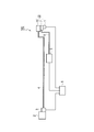
- FIG. 1 is a block diagram showing a configuration of a vehicle camera cleaning device according to an embodiment of the present invention.
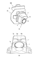
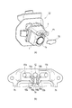
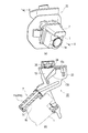
- FIG. 2 is a perspective view showing the configuration of the in-vehicle camera cleaning device according to one embodiment of the present invention.
- FIG. 2 (a) shows the cleaning device according to the present embodiment in the camera mounted on the rear part of the vehicle.
- FIG. 2B is a view of the cleaning device shown in FIG. 2A as viewed from the “A” direction.
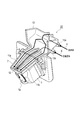
- FIG. 3 is a partially broken perspective view of the camera unit provided in the in-vehicle camera cleaning device according to the embodiment of the present invention.
- FIG. 4 is a cross-sectional view of the nozzle tip provided in the in-vehicle camera cleaning device according to one embodiment of the present invention, FIG.
- FIG. 4A is an exploded view of the nozzle tip, and FIG. These are sectional drawings of the part of the code
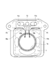
- FIG. 5 is an explanatory diagram showing the positional relationship between the nozzle tip provided in the in-vehicle camera cleaning device according to the embodiment of the present invention and the camera.
- FIG. 6 is a diagram illustrating a configuration of a vehicle-mounted camera cleaning device according to an embodiment of the present invention.
- FIG. 6A illustrates a camera mounted on a rear portion of a vehicle with the cleaning device according to the present embodiment.
- FIG. 6B is a cross-sectional view taken along line DD of the nozzle unit shown in FIG. 6A.
- FIG. 7 is a timing chart showing processing in a pressure cleaning mode executed by the on-vehicle camera cleaning device according to one embodiment of the present invention
- FIG. 7A is a timing chart showing driving of the cleaning liquid pump
- FIG. 7B is a timing chart showing driving of the air pump.
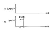
- FIG. 8 is a timing chart showing air blow mode processing executed by the on-vehicle camera cleaning device according to the embodiment of the present invention.
- FIG. 8A is a timing chart showing driving of the cleaning liquid pump.
- (B) is a timing chart which shows the drive of an air pump.
- FIG. 9 is a timing chart showing processing in a continuous water injection mode executed by the on-vehicle camera cleaning device according to one embodiment of the present invention
- FIG. 9A is a timing chart showing driving of the cleaning liquid pump
- FIG. 9 (b) is a timing chart showing driving of the air pump.
- FIG. 1 is a block diagram showing a configuration of a vehicle camera cleaning device according to an embodiment of the present invention.
- a cleaning apparatus 100 includes a cleaning liquid storage tank (primary tank) 2 that stores cleaning liquid, and a cleaning liquid pump 3 (cleaning liquid sending means) that sends out the cleaning liquid stored in the cleaning liquid storage tank 2. ), An air pump 5 (compressed air delivery means) for sending out compressed air, and a nozzle 7 for discharging cleaning liquid, compressed air, or a mixture of cleaning liquid and compressed air toward the lens surface of the camera 1. .
- the cleaning liquid pipe 4 that guides the cleaning liquid sent out by the cleaning liquid pump 3 to the secondary tank 13 that accumulates the cleaning liquid, and the air that leads the compressed air sent out by the air pump 5 to the nozzle 7 of the nozzle unit 22.
- a pipe 6 and a control unit (control means) 8 for controlling driving of the cleaning liquid pump 3 and the air pump 5 are provided.
- FIG. 2A is a perspective view showing a state in which the cleaning device 100 according to the present embodiment is installed in the camera 1 mounted on the rear part of the vehicle
- FIG. 2B is a cleaning shown in FIG. It is the figure which looked at the apparatus 100 from "A" direction.
- a nozzle unit 22 that is fixed to the rear part of the vehicle and cleans the lens surface 1a is provided in the vicinity of the side part of the camera 1 fixed to the rear part of the vehicle.
- the nozzle unit 22 is provided with a nozzle 7 for ejecting cleaning liquid and compressed air toward the lens surface 1a, and a cap 7d.
- the nozzle 7 is provided with two discharge ports 10a and 10b for ejecting cleaning liquid and compressed air at the tip thereof. That is, the foreign substance adhering to the lens surface 1a is removed by ejecting cleaning liquid and compressed air from the discharge ports 10a and 10b of the nozzle 7 toward the lens surface 1a.
- FIG. 3 is a partially broken perspective view of the nozzle unit 22 shown in FIG.
- the nozzle 7 provided on the tip side of the nozzle unit 22 is provided with an air passage 12 for introducing compressed air at the center thereof, and a cleaning liquid is introduced on both the left and right sides of the air passage 12.
- Cleaning liquid passages 11a and 11b are provided.
- the tips of the air passage 12 and the cleaning liquid passages 11a and 11b are bent substantially at right angles so as to face the lens surface 1a of the camera 1.
- a secondary tank 13 for temporarily accumulating the cleaning liquid is provided upstream of the cleaning liquid passages 11a and 11b.
- a plug 13 a for connecting the cleaning liquid pipe 4 and a plug 13 b for connecting the air pipe 6 are provided on the side of the secondary tank 13, and the plug 13 b is connected to the secondary tank 13. It is connected to the air passage 12 through a flow path provided below. That is, the compressed air introduced into the nozzle unit 22 via the plug 13b is directly introduced into the air passage 12.
- the plug 13a is connected to the secondary tank 13, and the cleaning liquid supplied via the plug 13a flows into the interior from above the secondary tank 13.
- the pipe connected from the plug 13a to the secondary tank 13 faces the vertical direction as indicated by reference numeral 23 in FIG. Details of the pipe 23 will be described later.
- the bottom of the secondary tank 13 is connected to the two cleaning liquid passages 11a and 11b, and is further provided at a position higher than the discharge ports 10a and 10b. Therefore, the compressed air sent out from the air pump 5 shown in FIG. 1 is introduced into the air passage 12 of the nozzle 7 via the air pipe 6, while the cleaning liquid sent out from the cleaning liquid pump 3 is sent to the secondary tank. After being accumulated in 13, the cleaning liquid passages 11a and 11b of the two systems are introduced. Further, the volume of the secondary tank 13 is smaller than that of the cleaning liquid storage tank 2 shown in FIG.
- FIG. 4B is an explanatory diagram showing the detailed configuration of the nozzle tip, and shows a cross-sectional view of the portion indicated by reference numeral P1 shown in FIG.
- the tip of the nozzle 7 is provided with an air passage 12 at the center, and two cleaning liquid passages 11 a and 11 b are provided so as to sandwich the air passage 12. That is, the cleaning liquid passage in the present embodiment is composed of two systems of cleaning liquid passages 11 a and 11 b provided so as to sandwich the air passage 12.
- the cleaning liquid passages 11a and 11b are connected to the front end portions 15a and 15b, respectively. At this time, the flow passage areas of the front end portions 15a and 15b are made smaller than the flow passage areas of the cleaning liquid passages 11a and 11b. Therefore, the flow rate of the cleaning liquid flowing through the cleaning liquid passages 11a and 11b increases in the tip portions 15a and 15b.
- the tip of the air passage 12 is branched into two tip portions 14a (first tip portion) and 14b (second tip portion). At this time, the flow passage areas of the tip portions 14 a and 14 b are made smaller than the flow passage area of the air passage 12. Therefore, the flow rate of the compressed air flowing through the air passage 12 increases when passing through the tip portions 14a and 14b.
- tip part 14a of the air path 12 merge, and form the combined flow path 16a (1st combined flow path), and this front-end
- the tip portion 15b of the other cleaning liquid passage 11b and the other tip portion 14b of the air passage 12 merge to form a joining passage 16b (second joining passage), and this tip is the discharge port 10b (FIG. 2B). See).
- the combined flow path 16a and the combined flow path 16b are directed in the direction of spreading toward the distal end side.
- the compressed air is injected at a higher flow rate, and further, When the compressed air is injected, the secondary tank 13 and the cleaning liquid passages 11a and 11b become negative pressure, and the cleaning liquid accumulated in the secondary tank 13 is sucked. For this reason, the compressed air and the cleaning liquid are ejected from the discharge ports 10a and 10b via the two combined flow paths 16a and 16b, and are sprayed onto the lens surface 1a. At this time, the liquid in which the cleaning liquid and the compressed air are mixed is ejected in the spreading direction as shown in FIG. 5, and the entire lens surface 1a can be cleaned.
- the ejection surface 7a at the tip of the nozzle 7 is configured to protrude forward from the surrounding side surface (nozzle tip surface) 7b. Therefore, it is possible to prevent the cleaning liquid sprayed from the discharge ports 10 a and 10 b from adhering to the side surface 7 b of the nozzle 7. Specifically, it is possible to prevent the cleaning liquid from adhering to the regions indicated by reference numerals P2 and P3 in FIG.
- FIG. 6B is a cross-sectional view taken along line DD of the nozzle unit 22 shown in FIG.
- a slight gap is provided between the bottom surface 7 c of the nozzle 7 and the top surface 1 b of the housing of the camera 1.
- the width of the gap is configured to become narrower toward the back side.
- a supply port 13c for supplying a cleaning liquid into the secondary tank 13 is provided at the upper part of the secondary tank 13 provided on the upstream side of the nozzle 7.
- the supply port 13c is provided with a pipe 23 that faces in the vertical direction.
- the pipe 23 is connected to the plug 13a shown in FIG.
- a check valve 24 is provided on the upper surface of the secondary tank 13.
- the check valve 24 is, for example, an umbrella valve, and when the pressure in the secondary tank 13 becomes negative, the valve is released and outside air is introduced from the vent hole 25 so that the pressure in the secondary tank 13 is reduced. When positive pressure is reached, the valve is closed to prevent release to the outside air. Therefore, when the secondary tank 13 becomes negative pressure, external air flows into the secondary tank 13, and the cleaning liquid can be prevented from flowing through the cleaning liquid pipe 4. That is, the secondary tank 13 includes a check valve that prevents the air from flowing out from the secondary tank 13 to the outside and opens the air inflow into the secondary tank 13 from the outside.
- the bottom surface 13d of the secondary tank 13 is inclined so as to descend toward the front side (the left side in the figure), and the outlet pipe and nozzle of the secondary tank 13 Similarly, the cleaning liquid passages 11 a and 11 b and the air passage 12 (see FIG. 3) provided in 7 are inclined so as to descend toward the front side.
- a pressure cleaning mode in which cleaning liquid and compressed air are jetted to clean the lens surface 1a
- an air blow mode in which only compressed air is sent out to remove water droplets attached to the lens surface 1a
- the cleaning liquid are intermittent.
- Three modes are set, a continuous water injection mode that drops on the lens surface 1a and makes it difficult for dirt to adhere to the lens surface 1a.
- the pressure washing mode will be described.
- the cleaning liquid pump 3 is driven for a short time to accumulate the cleaning liquid in the secondary tank 13, and at the same time, the air pump 5 is driven. Specifically, as shown in FIGS. 7A and 7B, both the cleaning liquid pump 3 and the air pump 5 are driven at time t0.
- the cleaning liquid stored in the cleaning liquid storage tank (primary tank) 2 is supplied to the secondary tank 13 via the cleaning liquid pipe 4 at time t0 to t1 (for example, 200 msec).
- Cleaning fluid accumulates in Times t0 to t1 are set as times when the cleaning liquid is filled in the secondary tank 13 by the cleaning liquid pump 3.
- the compressed air delivered from the air pump 5 is introduced into the air passage 12 in the nozzle 7 shown in FIG. 3 via the air pipe 6, and then this compressed air is shown in FIG. 4 (b). It is sent from the front end portions 14a and 14b toward the combined flow paths 16a and 16b.
- the air flow rate is increased at the front end portions 14a and 14b. Therefore, the tip portions 15a and 15b of the cleaning liquid passages 11a and 11b on the downstream side of the combined flow paths 16a and 16b become negative pressure, the cleaning liquid accumulated in the secondary tank 13 is sucked, and the sucked cleaning liquid is washed with the cleaning liquid passage 11a.
- the cleaning liquid becomes mist from the combined flow paths 16a and 16b and is jetted together with the compressed air. Therefore, the mist-like cleaning liquid can be ejected and sprayed onto the lens surface 1a from the discharge ports 10a and 10b which are the tips of the joint channels 16a and 16b. For this reason, the foreign matter adhering to the lens surface 1a can be removed by the synergistic action of the mist-like cleaning liquid and the air pressure.
- the air pump 5 (compressed air delivery means) is driven to inject compressed air from the discharge ports 10a and 10b, and the cleaning liquid passages 11a and 11a are negatively generated by the compressed air injection.
- the cleaning liquid supplied to 11b is sucked and the cleaning liquid is ejected from the discharge ports 10a and 10b, and the lens surface 1a is cleaned with the jetted compressed air and the cleaning liquid.
- the cleaning liquid pump 3 cleaning liquid sending means
- continuously sending compressed air from the air pump 5 compressed air sending means
- This pressure cleaning mode is suitable for use in removing foreign matters such as mud adhering to the lens surface 1a.
- the driving time of the cleaning liquid pump 3 shown in FIG. 7A is set long (for example, 400 msec between t0 and t1), the cleaning liquid accumulated in the secondary tank 13 is pushed out by the pressure of the cleaning liquid pump 3. Since the cleaning liquid can be pressurized and supplied to the cleaning liquid passages 11a and 11b, the lens surface 1a can be cleaned at a high pressure.
- the air blow mode In the air blow mode, only the air pump 5 is driven in a state where no cleaning liquid is accumulated in the secondary tank 13. Specifically, as shown in FIG. 8A, the cleaning liquid pump 3 is stopped, and as shown in FIG. 8B, the air pump 5 is driven at time t10 to t11 (for example, 2 seconds). Then, the compressed air is jetted from the discharge ports 10a and 10b via the front end portions 14a and 14b of the air passage 12 and the combined channels 16a and 16b, and is blown onto the lens surface 1a. As a result, water droplets attached to the lens surface 1a of the camera 1 can be removed by air pressure.
- the pipe 23 connected to the secondary tank 13 is substantially vertically oriented as shown in FIG. 6B, and the bottom surface 13d of the secondary tank 13 is located more than the discharge ports 10a and 10b. Since the bottom surface 13d of the secondary tank 13 and the pipe for the cleaning liquid are inclined downward, the cleaning liquid does not remain in the secondary tank 13 and the pipe. For this reason, even when the compressed air is injected and the inside of the secondary tank 13 becomes a negative pressure, it is possible to prevent the cleaning liquid from being introduced into the combined flow paths 16a and 16b, and to prevent the cleaning liquid from being mixed into the compressed air. it can.
- the compressed air is ejected to remove water droplets adhering to the lens surface 1a, it is possible to avoid the problem that the cleaning liquid mixed in the compressed air adheres to the lens surface 1a again. That is, in the air blow mode, the supply of the cleaning liquid by the cleaning liquid pump 3 (cleaning liquid sending means) is stopped, and the compressed air is sent to the air pipe 6 by the air pump 5 (compressed air sending means) in a state where the supply of the cleaning liquid is cut off. In this mode, the lens surface 1a is cleaned by ejecting compressed air from the discharge ports 10a and 10b.
- the air blow mode is suitable for removing water droplets attached to the lens surface 1a.
- the continuous water injection mode the cleaning liquid is supplied from the cleaning liquid pump 3 into the secondary tank 13, and the air pump 5 is intermittently driven to drop the cleaning liquid onto the lens surface 1a.
- the cleaning liquid pump 3 is driven at time t20 to t21 to accumulate the cleaning liquid in the secondary tank 13, and then the air pump 5 at time t22.
- the cleaning liquid is dropped on the lens surface 1a little by little.
- the cleaning liquid is dropped in small amounts (for example, 0.25 cc) on the lens surface 1a at a time t22 to t23 of 30 msec.
- the lens surface 1a can be kept wet all the time, and it is possible to prevent the contamination component contained in the water droplets rolled up by the vehicle when it rains. That is, in the continuous water injection mode, the compressed air is intermittently ejected from the discharge ports 10a and 10b a plurality of times, the cleaning liquid is sucked by the negative pressure generated by the injection of the compressed air, and the cleaning liquid is discharged from the discharge ports 10a and 10b to the lens surface 1a. Is a mode for injecting.
- the continuous water injection mode is suitable for preventing the contamination component from being deposited on the lens surface 1a by keeping the lens surface 1a wet when it rains.
- Each of the above-described cleaning modes may be set manually by the driver of the vehicle, or the camera 1 detects a dirty state or a weather state, and automatically selects a cleaning mode according to the detection results. You may make it wash
- the compressed air is jetted to discharge all the cleaning liquid remaining in the secondary tank 13 to make it empty.
- the cleaning liquid sprayed together with the compressed air adheres to the surface of the lens surface 1a, the image picked up by the camera 1 may be affected.
- the cleaning liquid in the secondary tank 13 is affected. Is discharged, compressed air is sprayed for a predetermined time (for example, 30 seconds) to dry the lens surface 1a.
- the cleaning water remaining in the secondary tank 13 is reduced, if the cleaning water is ejected by ejecting the compressed air, the cleaning water is intermittently ejected.
- the compressed air may be jetted when the vehicle speed drops below the driving vehicle speed (for example, 30 Km / h) of an application that uses an image captured by the camera 1.
- the air passage 12 is provided at the tip of the nozzle 7, the cleaning liquid passages 11 a and 11 b are provided in the vicinity of the air passage 12, and the air The front end portions 14a and 14b of the passage 12 and the front end portions 15a and 15b of the cleaning liquid passages 11a and 11b are merged.
- a secondary tank 13 is provided upstream of the cleaning liquid passages 11 a and 11 b, and a certain amount of cleaning liquid is accumulated in the secondary tank 13. Accordingly, the compressed air and the cleaning liquid accumulated in the secondary tank 13 can be mixed and sprayed onto the lens surface 1a of the camera 1, and the lens surface 1a can be cleaned with a small amount of cleaning liquid.
- the secondary tank 13 is set to a negative pressure, the cleaning liquid is sucked from the cleaning liquid passages 11a and 11b, and the cleaning liquid is supplied to the combined passages 16a and 16b. And the compressed air are mixed and ejected from the discharge ports 10a and 10b, so that the cleaning liquid can be made mist and the amount of the cleaning liquid required for cleaning can be further reduced.
- the pipe 23 (see FIG. 6) for supplying the cleaning liquid to the secondary tank 13 is oriented in the vertical direction. That is, the connection part of the cleaning liquid pipe to the secondary tank 13 is provided in the vertical direction. Therefore, when the supply of the cleaning liquid from the cleaning liquid pump 3 (see FIG. 1) is stopped, it is possible to prevent the cleaning liquid accumulated in the pipeline from inadvertently flowing into the secondary tank 13. For this reason, for example, when jetting compressed air in the air blow mode, it is possible to prevent the cleaning liquid from being mixed.
- the bottom surface 13d of the secondary tank 13 is provided at a position higher than the discharge ports 10a and 10b, and the cleaning liquid passages 11a and 11b connected to the nozzle 7 are connected to the discharge ports 10a and 10b from the secondary tank 13. Since it is arranged to be inclined downward toward 10b, the cleaning liquid accumulated in the secondary tank 13 and the cleaning liquid passages 11a, 11b is sent to the discharge ports 10a, 10b without remaining. Therefore, the remaining cleaning liquid can be prevented from being ejected irregularly.
- the compressed air and the cleaning liquid are combined at the tip of the nozzle 7.
- the present invention is not limited to this, and the air passage and the cleaning liquid passage are arranged close to each other.
- the cleaning liquid supplied from the cleaning liquid passage may be jetted in a mist form using the negative pressure at this time.
- the tip portions 14a and 15a and 14b and 15b shown in FIG. 4 (b) do not merge and are jetted in a state where they are close to each other.
- the present invention can be used for effectively cleaning the lens surface of a camera mounted on a vehicle with a small amount of cleaning liquid.
- the cleaning liquid necessary for cleaning is stored in the secondary tank in advance, so it is possible to hold an appropriate amount of cleaning liquid in advance, and it is effective with less cleaning liquid without discharging excess cleaning liquid.
- the lens surface can be cleaned.
Landscapes
- Engineering & Computer Science (AREA)
- Multimedia (AREA)
- Signal Processing (AREA)
- Physics & Mathematics (AREA)
- General Physics & Mathematics (AREA)
- Mechanical Engineering (AREA)
- Automation & Control Theory (AREA)
- Studio Devices (AREA)
Abstract
Priority Applications (7)
| Application Number | Priority Date | Filing Date | Title |
|---|---|---|---|
| RU2015104343/11A RU2566169C1 (ru) | 2012-07-11 | 2013-07-09 | Устройство для очистки для установленной на транспортном средстве камеры |
| BR112015000656-6A BR112015000656B1 (pt) | 2012-07-11 | 2013-07-09 | Dispositivo de limpeza para câmeras montadas em veículos |
| US14/413,904 US10011251B2 (en) | 2012-07-11 | 2013-07-09 | Cleaning device for vehicle-mounted camera |
| JP2014524813A JP5892249B2 (ja) | 2012-07-11 | 2013-07-09 | カメラの洗浄装置 |
| MX2015000269A MX337174B (es) | 2012-07-11 | 2013-07-09 | Dispositivo de limpieza para camara montada en vehiculo. |
| CN201380036948.6A CN104470770B (zh) | 2012-07-11 | 2013-07-09 | 车载摄像机的清洗装置 |
| EP13816304.3A EP2873571B1 (fr) | 2012-07-11 | 2013-07-09 | Dispositif de nettoyage de caméra embarquée |
Applications Claiming Priority (3)
| Application Number | Priority Date | Filing Date | Title |
|---|---|---|---|
| JP2012155360 | 2012-07-11 | ||
| JP2012155357 | 2012-07-11 | ||
| JP2012-155360 | 2012-07-11 |
Publications (1)
| Publication Number | Publication Date |
|---|---|
| WO2014010580A1 true WO2014010580A1 (fr) | 2014-01-16 |
Family
ID=51392984
Family Applications (2)
| Application Number | Title | Priority Date | Filing Date |
|---|---|---|---|
| PCT/JP2013/068716 Ceased WO2014010579A1 (fr) | 2012-07-11 | 2013-07-09 | Dispositif de nettoyage de caméra embarquée |
| PCT/JP2013/068717 Ceased WO2014010580A1 (fr) | 2012-07-11 | 2013-07-09 | Dispositif de nettoyage de caméra embarquée |
Family Applications Before (1)
| Application Number | Title | Priority Date | Filing Date |
|---|---|---|---|
| PCT/JP2013/068716 Ceased WO2014010579A1 (fr) | 2012-07-11 | 2013-07-09 | Dispositif de nettoyage de caméra embarquée |
Country Status (1)
| Country | Link |
|---|---|
| WO (2) | WO2014010579A1 (fr) |
Cited By (20)
| Publication number | Priority date | Publication date | Assignee | Title |
|---|---|---|---|---|
| DE102014117165A1 (de) | 2014-11-24 | 2016-05-25 | Kautex Textron Gmbh & Co. Kg | Fahrzeugintegriertes Sicht- und Reinigungssystem |
| JP2016179767A (ja) * | 2015-03-24 | 2016-10-13 | トヨタ自動車株式会社 | 車両用制御装置、車両用制御プログラム、及び車両 |
| KR20170012125A (ko) * | 2015-07-22 | 2017-02-02 | 발레오 시스뗌므 데쉬야지 | 자동차용 센서 세척 장치 |
| JP2017154527A (ja) * | 2016-02-29 | 2017-09-07 | アスモ株式会社 | 車載センサ洗浄装置 |
| US10035498B2 (en) | 2015-04-22 | 2018-07-31 | Ford Global Technologies, Llc | Vehicle camera cleaning system |
| DE102018117709A1 (de) | 2017-07-25 | 2019-01-31 | Aisin Seiki Kabushiki Kaisha | Reinigungssystem |
| WO2019124014A1 (fr) * | 2017-12-18 | 2019-06-27 | 株式会社オートネットワーク技術研究所 | Dispositif d'imagerie embarqué, procédé de nettoyage et programme informatique |
| JP2019523175A (ja) * | 2016-07-28 | 2019-08-22 | ヴァレオ システム デシュヤージュValeo Systemes D’Essuyage | 光学センサを保護するための装置、及び光学センサを備える運転支援システム |
| US10409055B2 (en) | 2017-11-30 | 2019-09-10 | Veoneer Us, Inc. | Self-cleaning vehicle camera assemblies |
| JP2019525865A (ja) * | 2016-07-18 | 2019-09-12 | ウーバー テクノロジーズ,インコーポレイテッド | 車輌用センサクリーニングシステム |
| CN110740907A (zh) * | 2017-04-11 | 2020-01-31 | 大陆汽车有限责任公司 | 用于清洁光学或光电设备的透明盖的清洁设备 |
| KR20200058685A (ko) * | 2018-11-20 | 2020-05-28 | 현대자동차주식회사 | 카메라 모니터링 시스템 |
| EP3715193A1 (fr) | 2019-03-26 | 2020-09-30 | Clarion Co., Ltd. | Unité de buse de nettoyage et unité de caméra embarquée |
| JP2021508595A (ja) * | 2017-12-30 | 2021-03-11 | ディエルエイチ・ボウルズ・インコーポレイテッドdlhBOWLES Inc. | 自動車の画像センサー表面の洗浄乾燥システム |
| WO2021096042A1 (fr) * | 2019-11-14 | 2021-05-20 | 주식회사 니프코코리아 | Buse composite pour automobile |
| JP2022080146A (ja) * | 2020-11-17 | 2022-05-27 | 株式会社デンソーテン | ノズル装置 |
| RU2775791C1 (ru) * | 2021-03-26 | 2022-07-11 | Общество с ограниченной ответственностью «Яндекс Беспилотные Технологии» | Система и способ очистки поверхности сенсора на беспилотном автомобиле |
| CN115743040A (zh) * | 2022-10-13 | 2023-03-07 | 文远苏行(江苏)科技有限公司 | 传感器清洗控制方法、装置、设备及存储介质 |
| US12330598B2 (en) | 2021-03-26 | 2025-06-17 | Y.E. Hub Armenia LLC | System for and method of cleaning a surface of a sensor on a self-driving car |
| WO2025192651A1 (fr) * | 2024-03-13 | 2025-09-18 | 株式会社小糸製作所 | Dispositif de nettoyage et ensemble capteur |
Families Citing this family (14)
| Publication number | Priority date | Publication date | Assignee | Title |
|---|---|---|---|---|
| EP2949520B1 (fr) * | 2014-05-27 | 2018-03-21 | Fico Transpar, S.A. | Système de nettoyage d'une lentille optique montée sur un véhicule |
| CN115257544B (zh) * | 2015-03-23 | 2025-05-16 | 株式会社小糸制作所 | 车辆用拍摄装置、车辆用灯具以及电子控制单元 |
| JP6439589B2 (ja) * | 2015-05-28 | 2018-12-19 | 株式会社デンソー | 車載光学センサ洗浄システム及び車載光学センサ洗浄方法 |
| DE102016107380B4 (de) * | 2015-05-20 | 2025-12-11 | Denso Corporation | Anlage zur Reinigung eines fahrzeugeigenen optischen Sensors und Verfahren dafür |
| JP6536167B2 (ja) * | 2015-05-20 | 2019-07-03 | 株式会社デンソー | 車載光学センサ取付ブラケット、及び車載光学センサユニット |
| EP3318454B1 (fr) * | 2015-06-30 | 2021-06-02 | Koito Manufacturing Co., Ltd. | Dispositif d'élimination de substance étrangère, et véhicule équipé de celui-ci |
| FR3040952B1 (fr) * | 2015-09-14 | 2017-09-08 | Valeo Systemes Dessuyage | Systeme de detection optique pour vehicule automobile et procede de nettoyage de l’optique du systeme de detection optique |
| FR3048664B1 (fr) * | 2016-03-14 | 2018-04-13 | Valeo Systemes D'essuyage | Dispositif de nettoyage d'un systeme de detection optique pour vehicule automobile |
| JP6841159B2 (ja) * | 2017-05-24 | 2021-03-10 | トヨタ自動車株式会社 | 運転支援装置 |
| US11738720B2 (en) * | 2017-08-30 | 2023-08-29 | Koito Manufacturing Co., Ltd. | Vehicle cleaner unit and vehicle provided with vehicle cleaner unit |
| SI3594167T1 (sl) * | 2018-07-13 | 2021-11-30 | Epsilon Kran Gmbh. | Žerjav s sistemom za zajemanje slike |
| JP7131326B2 (ja) | 2018-11-20 | 2022-09-06 | トヨタ自動車株式会社 | センサ搭載構造 |
| FR3121104A1 (fr) | 2021-03-23 | 2022-09-30 | Valeo Systemes D'essuyage | Dispositif de nettoyage d’une surface de détection d’un dispositif de détection. |
| EP4194283B1 (fr) * | 2021-12-08 | 2024-06-12 | A. Raymond et Cie | Système de distribution de fluide pour nettoyer des surfaces de véhicule |
Citations (4)
| Publication number | Priority date | Publication date | Assignee | Title |
|---|---|---|---|---|
| JP2001171491A (ja) | 1999-12-16 | 2001-06-26 | Matsushita Electric Ind Co Ltd | 車載カメラ装置及び車載カメラの洗浄方法 |
| JP2003203884A (ja) * | 2002-01-07 | 2003-07-18 | Tokyo Seimitsu Co Ltd | ダイシングマシンの洗浄装置及び洗浄方法 |
| JP2007318355A (ja) * | 2006-05-24 | 2007-12-06 | Matsushita Electric Ind Co Ltd | 撮像装置およびレンズ汚れ検出方法 |
| JP2011240920A (ja) * | 2010-04-20 | 2011-12-01 | Denso Corp | 車載光学センサカバー及び車載光学センサ装置 |
-
2013
- 2013-07-09 WO PCT/JP2013/068716 patent/WO2014010579A1/fr not_active Ceased
- 2013-07-09 WO PCT/JP2013/068717 patent/WO2014010580A1/fr not_active Ceased
Patent Citations (4)
| Publication number | Priority date | Publication date | Assignee | Title |
|---|---|---|---|---|
| JP2001171491A (ja) | 1999-12-16 | 2001-06-26 | Matsushita Electric Ind Co Ltd | 車載カメラ装置及び車載カメラの洗浄方法 |
| JP2003203884A (ja) * | 2002-01-07 | 2003-07-18 | Tokyo Seimitsu Co Ltd | ダイシングマシンの洗浄装置及び洗浄方法 |
| JP2007318355A (ja) * | 2006-05-24 | 2007-12-06 | Matsushita Electric Ind Co Ltd | 撮像装置およびレンズ汚れ検出方法 |
| JP2011240920A (ja) * | 2010-04-20 | 2011-12-01 | Denso Corp | 車載光学センサカバー及び車載光学センサ装置 |
Non-Patent Citations (1)
| Title |
|---|
| See also references of EP2873571A4 |
Cited By (40)
| Publication number | Priority date | Publication date | Assignee | Title |
|---|---|---|---|---|
| CN107000705B (zh) * | 2014-11-24 | 2020-01-10 | 考特克斯·特克斯罗恩有限公司及两合公司 | 集成的机载车辆视野和清洁系统 |
| WO2016083317A1 (fr) * | 2014-11-24 | 2016-06-02 | Kautex Textron Gmbh & Co. Kg | Système intégré embarqué de vision et nettoyage de véhicule |
| DE102014117165A1 (de) | 2014-11-24 | 2016-05-25 | Kautex Textron Gmbh & Co. Kg | Fahrzeugintegriertes Sicht- und Reinigungssystem |
| US10293794B2 (en) | 2014-11-24 | 2019-05-21 | Kautext Textron Gmbh & Co. Kg | Integrated on-board vehicle vision and cleaning system |
| KR20170087485A (ko) * | 2014-11-24 | 2017-07-28 | 카우텍스 텍스트론 게엠베하 운트 콤파니 카게 | 일체형 온보드 차량 시야 및 클리닝 시스템 |
| CN107000705A (zh) * | 2014-11-24 | 2017-08-01 | 考特克斯·特克斯罗恩有限公司及两合公司 | 集成的机载车辆视野和清洁系统 |
| KR101971386B1 (ko) | 2014-11-24 | 2019-04-22 | 카우텍스 텍스트론 게엠베하 운트 콤파니 카게 | 일체형 온보드 차량 시야 및 클리닝 시스템 |
| RU2659280C1 (ru) * | 2014-11-24 | 2018-06-29 | Каутекс Текстрон Гмбх Унд Ко. Кг | Интегрированная бортовая система обзора и очистки транспортного средства |
| JP2016179767A (ja) * | 2015-03-24 | 2016-10-13 | トヨタ自動車株式会社 | 車両用制御装置、車両用制御プログラム、及び車両 |
| US9821771B2 (en) | 2015-03-24 | 2017-11-21 | Toyota Jidosha Kabushiki Kaisha | Control device for a vehicle, storage medium of control program for vehicle, and vehicle |
| RU2682692C2 (ru) * | 2015-04-22 | 2019-03-20 | ФОРД ГЛОУБАЛ ТЕКНОЛОДЖИЗ, ЭлЭлСи | Система очистки камеры транспортного средства |
| US10035498B2 (en) | 2015-04-22 | 2018-07-31 | Ford Global Technologies, Llc | Vehicle camera cleaning system |
| KR102535999B1 (ko) * | 2015-07-22 | 2023-05-23 | 발레오 시스뗌므 데쉬야지 | 자동차용 센서 세척 장치 |
| JP2017024713A (ja) * | 2015-07-22 | 2017-02-02 | ヴァレオ システム デシュヤージュValeo Systemes D’Essuyage | 自動車用センサを洗浄するための装置 |
| KR20170012125A (ko) * | 2015-07-22 | 2017-02-02 | 발레오 시스뗌므 데쉬야지 | 자동차용 센서 세척 장치 |
| JP2017154527A (ja) * | 2016-02-29 | 2017-09-07 | アスモ株式会社 | 車載センサ洗浄装置 |
| JP2019525865A (ja) * | 2016-07-18 | 2019-09-12 | ウーバー テクノロジーズ,インコーポレイテッド | 車輌用センサクリーニングシステム |
| US11079592B2 (en) | 2016-07-28 | 2021-08-03 | Valeo Systèmes d'Essuyage | Device for protecting an optical sensor and driving aid system comprising an optical sensor |
| JP2019523175A (ja) * | 2016-07-28 | 2019-08-22 | ヴァレオ システム デシュヤージュValeo Systemes D’Essuyage | 光学センサを保護するための装置、及び光学センサを備える運転支援システム |
| CN110740907A (zh) * | 2017-04-11 | 2020-01-31 | 大陆汽车有限责任公司 | 用于清洁光学或光电设备的透明盖的清洁设备 |
| DE102018117709A1 (de) | 2017-07-25 | 2019-01-31 | Aisin Seiki Kabushiki Kaisha | Reinigungssystem |
| US10409055B2 (en) | 2017-11-30 | 2019-09-10 | Veoneer Us, Inc. | Self-cleaning vehicle camera assemblies |
| WO2019124014A1 (fr) * | 2017-12-18 | 2019-06-27 | 株式会社オートネットワーク技術研究所 | Dispositif d'imagerie embarqué, procédé de nettoyage et programme informatique |
| JP2021508595A (ja) * | 2017-12-30 | 2021-03-11 | ディエルエイチ・ボウルズ・インコーポレイテッドdlhBOWLES Inc. | 自動車の画像センサー表面の洗浄乾燥システム |
| JP7307730B2 (ja) | 2017-12-30 | 2023-07-12 | ディエルエイチ・ボウルズ・インコーポレイテッド | 自動車の画像センサー表面の洗浄乾燥システム |
| KR20200058685A (ko) * | 2018-11-20 | 2020-05-28 | 현대자동차주식회사 | 카메라 모니터링 시스템 |
| KR102552165B1 (ko) | 2018-11-20 | 2023-07-05 | 현대자동차주식회사 | 카메라 모니터링 시스템 |
| US11458934B2 (en) | 2019-03-26 | 2022-10-04 | Clarion Co., Ltd. | Cleaning nozzle unit and on-vehicle camera unit |
| EP3715193A1 (fr) | 2019-03-26 | 2020-09-30 | Clarion Co., Ltd. | Unité de buse de nettoyage et unité de caméra embarquée |
| KR20210058555A (ko) * | 2019-11-14 | 2021-05-24 | 주식회사 니프코코리아 | 자동차용 복합노즐 |
| CN114667244A (zh) * | 2019-11-14 | 2022-06-24 | 利富高(韩国)股份有限公司 | 汽车用复合喷嘴 |
| KR102260813B1 (ko) * | 2019-11-14 | 2021-06-07 | 주식회사 니프코코리아 | 자동차용 복합노즐 |
| WO2021096042A1 (fr) * | 2019-11-14 | 2021-05-20 | 주식회사 니프코코리아 | Buse composite pour automobile |
| US12337802B2 (en) | 2019-11-14 | 2025-06-24 | Nifco Korea Inc. | Composite nozzle for automobile |
| JP2022080146A (ja) * | 2020-11-17 | 2022-05-27 | 株式会社デンソーテン | ノズル装置 |
| JP7617727B2 (ja) | 2020-11-17 | 2025-01-20 | 株式会社デンソーテン | ノズル装置 |
| RU2775791C1 (ru) * | 2021-03-26 | 2022-07-11 | Общество с ограниченной ответственностью «Яндекс Беспилотные Технологии» | Система и способ очистки поверхности сенсора на беспилотном автомобиле |
| US12330598B2 (en) | 2021-03-26 | 2025-06-17 | Y.E. Hub Armenia LLC | System for and method of cleaning a surface of a sensor on a self-driving car |
| CN115743040A (zh) * | 2022-10-13 | 2023-03-07 | 文远苏行(江苏)科技有限公司 | 传感器清洗控制方法、装置、设备及存储介质 |
| WO2025192651A1 (fr) * | 2024-03-13 | 2025-09-18 | 株式会社小糸製作所 | Dispositif de nettoyage et ensemble capteur |
Also Published As
| Publication number | Publication date |
|---|---|
| WO2014010579A1 (fr) | 2014-01-16 |
Similar Documents
| Publication | Publication Date | Title |
|---|---|---|
| JP5892249B2 (ja) | カメラの洗浄装置 | |
| JP6090319B2 (ja) | 車載カメラの洗浄装置 | |
| WO2014010580A1 (fr) | Dispositif de nettoyage de caméra embarquée | |
| JP6090318B2 (ja) | 車載カメラの洗浄装置及び車載カメラの洗浄方法 | |
| US20110292212A1 (en) | Washer nozzle for vehicle mounted camera, vehicle mounted camera, and washer device for vehicle | |
| JP6998328B2 (ja) | 車両用クリーナシステムおよび車両用クリーナシステムを備える車両 | |
| JP2012201122A (ja) | 車載カメラ用ノズル装置、清掃装置付き車載カメラ、及び車載カメラ用清掃システム | |
| JP4513889B2 (ja) | ウォッシャノズル付カメラおよびウォッシャノズル | |
| JP5529782B2 (ja) | ウォッシャノズル付き車載カメラ及び車載カメラ用洗浄システム | |
| JP5643157B2 (ja) | 車載カメラ用ウォッシャノズル及び車載カメラ洗浄システム | |
| JP2011245989A (ja) | 車載カメラ用ウォッシャノズル、車載カメラ、及び車両用ウォッシャ装置 | |
| JP2012035654A (ja) | 車載カメラ用ノズル装置、清掃装置付き車載カメラ、及び車載カメラ用清掃システム | |
| JP2014201150A (ja) | 車載用撮像装置、光学部材の汚れ防止方法、及び、カメラモジュール | |
| JP2004182080A (ja) | 赤外線カメラ搭載車両および赤外線カメラシステム | |
| JP2013154771A (ja) | 車載カメラ装置 | |
| US20180257719A1 (en) | Vehicle front structure | |
| CN120322358A (zh) | 用于清洁光学元件的表面的装置、检测系统和交通工具 |
Legal Events
| Date | Code | Title | Description |
|---|---|---|---|
| 121 | Ep: the epo has been informed by wipo that ep was designated in this application |
Ref document number: 13816304 Country of ref document: EP Kind code of ref document: A1 |
|
| ENP | Entry into the national phase |
Ref document number: 2014524813 Country of ref document: JP Kind code of ref document: A |
|
| WWE | Wipo information: entry into national phase |
Ref document number: MX/A/2015/000269 Country of ref document: MX |
|
| WWE | Wipo information: entry into national phase |
Ref document number: 14413904 Country of ref document: US |
|
| NENP | Non-entry into the national phase |
Ref country code: DE |
|
| WWE | Wipo information: entry into national phase |
Ref document number: IDP00201500176 Country of ref document: ID |
|
| REEP | Request for entry into the european phase |
Ref document number: 2013816304 Country of ref document: EP |
|
| WWE | Wipo information: entry into national phase |
Ref document number: 2013816304 Country of ref document: EP |
|
| ENP | Entry into the national phase |
Ref document number: 2015104343 Country of ref document: RU Kind code of ref document: A |
|
| REG | Reference to national code |
Ref country code: BR Ref legal event code: B01A Ref document number: 112015000656 Country of ref document: BR |
|
| ENP | Entry into the national phase |
Ref document number: 112015000656 Country of ref document: BR Kind code of ref document: A2 Effective date: 20150112 |
|
| ENPC | Correction to former announcement of entry into national phase, pct application did not enter into the national phase |
Ref country code: BR Free format text: ANULADA A PUBLICACAO CODIGO 1.3 NA RPI NO 2425 DE 27/06/2017 POR TER SIDO INDEVIDA. |
|
| REG | Reference to national code |
Ref country code: BR Ref legal event code: B01E Ref document number: 112015000656 Country of ref document: BR Kind code of ref document: A2 Free format text: APRESENTE A TRADUCAO SIMPLES DA FOLHA DE ROSTO DA CERTIDAO DE DEPOSITO DA PRIORIDADE JP 2012-155360; OU DECLARACAO DE QUE OS DADOS DO PEDIDO INTERNACIONAL ESTAO FIELMENTE CONTIDOS NA PRIORIDADE REIVINDICADA, CONTENDO TODOS OS DADOS IDENTIFICADORES DESTA (TITULARES, NUMERO DE REGISTRO, DATA E TITULO), CONFORME O PARAGRAFO UNICO DO ART. 25 DA RESOLUCAO 77/2013. |
|
| ENP | Entry into the national phase |
Ref document number: 112015000656 Country of ref document: BR Kind code of ref document: A2 Effective date: 20150112 |