WO2014013532A1 - Dispositif de mesure d'équilibre pour roue de vélo - Google Patents
Dispositif de mesure d'équilibre pour roue de vélo Download PDFInfo
- Publication number
- WO2014013532A1 WO2014013532A1 PCT/JP2012/008192 JP2012008192W WO2014013532A1 WO 2014013532 A1 WO2014013532 A1 WO 2014013532A1 JP 2012008192 W JP2012008192 W JP 2012008192W WO 2014013532 A1 WO2014013532 A1 WO 2014013532A1
- Authority
- WO
- WIPO (PCT)
- Prior art keywords
- bicycle wheel
- axle
- support member
- wheel
- balance
- Prior art date
- Legal status (The legal status is an assumption and is not a legal conclusion. Google has not performed a legal analysis and makes no representation as to the accuracy of the status listed.)
- Ceased
Links
Images


Classifications
-
- G—PHYSICS
- G01—MEASURING; TESTING
- G01M—TESTING STATIC OR DYNAMIC BALANCE OF MACHINES OR STRUCTURES; TESTING OF STRUCTURES OR APPARATUS, NOT OTHERWISE PROVIDED FOR
- G01M1/00—Testing static or dynamic balance of machines or structures
- G01M1/30—Compensating imbalance
- G01M1/32—Compensating imbalance by adding material to the body to be tested, e.g. by correcting-weights
- G01M1/326—Compensating imbalance by adding material to the body to be tested, e.g. by correcting-weights the body being a vehicle wheel
-
- F—MECHANICAL ENGINEERING; LIGHTING; HEATING; WEAPONS; BLASTING
- F16—ENGINEERING ELEMENTS AND UNITS; GENERAL MEASURES FOR PRODUCING AND MAINTAINING EFFECTIVE FUNCTIONING OF MACHINES OR INSTALLATIONS; THERMAL INSULATION IN GENERAL
- F16F—SPRINGS; SHOCK-ABSORBERS; MEANS FOR DAMPING VIBRATION
- F16F15/00—Suppression of vibrations in systems; Means or arrangements for avoiding or reducing out-of-balance forces, e.g. due to motion
- F16F15/32—Correcting- or balancing-weights or equivalent means for balancing rotating bodies, e.g. vehicle wheels
- F16F15/324—Correcting- or balancing-weights or equivalent means for balancing rotating bodies, e.g. vehicle wheels the rotating body being a vehicle wheel
-
- G—PHYSICS
- G01—MEASURING; TESTING
- G01M—TESTING STATIC OR DYNAMIC BALANCE OF MACHINES OR STRUCTURES; TESTING OF STRUCTURES OR APPARATUS, NOT OTHERWISE PROVIDED FOR
- G01M1/00—Testing static or dynamic balance of machines or structures
- G01M1/12—Static balancing; Determining position of centre of gravity
- G01M1/122—Determining position of centre of gravity
Definitions
- the present invention relates to a bicycle wheel balance measuring device, and more particularly to a bicycle wheel balance measuring device capable of easily measuring the static balance of a wheel.
- a hub of a bicycle wheel (hereinafter simply referred to as a wheel) is arranged in a horizontal direction so that the wheel can rotate freely. In this state, it rotates and stops so that the heavy part of the wheel is on the lower side. At this time, a correction weight having an appropriate weight is attached to the position of the rim located above the wheel. And this operation is performed several times and it adjusts so that a specific location may not be arrange
- Non-Patent Document 1 discloses a device that rotates a bicycle wheel at high speed and measures a static balance state based on its vibration state.
- Patent Document 1 discloses a device for detecting a rim mismatch as a device for detecting a mismatch of a wheel having a spoke such as a bicycle wheel.
- Patent Literature 2 discloses a device that automatically calculates and specifies a balance weight imbalance of an automobile wheel and calculates a mounting position of a correction weight.
- Nippon Robotics Co., Ltd. “Wheel Balancer” catalog See JP-A-53-089102 See Table 02/066949
- the measurement of the balance state depends solely on human senses, and the weight of the correction weight is also determined by trial and error, so the processing time is long. Take it.
- Non-Patent Document 1 those described in Utility Model Registration Document 1, and those described in Patent Document 2 require a large-scale device, and can easily measure the balance of a bicycle wheel. Can not.
- the present invention has been made in view of the above-described problems, and an object of the present invention is to provide a bicycle wheel balance measuring device capable of easily and accurately measuring a bicycle wheel balance with a simple device.
- the invention according to claim 1, which solves the above-described problem, is a state in which the bicycle wheel is rotatable and detachably attached to the flat board and the axle one end side of the bicycle wheel.
- An axle support member having a fulcrum portion projecting in the axle direction and capable of supporting the bicycle wheel in a rotatable state; and the axle support member disposed on the substrate and having the bicycle wheel attached thereto.
- the fulcrum part is arranged on the substrate, and the load applied to the one part of the outer peripheral part is measured by applying a load to only one part of the outer peripheral part of the fulcrum part and the bicycle wheel. And a load measuring device that can be used.
- the invention according to claim 2 is the bicycle wheel balance measuring apparatus according to claim 1, wherein the axle support member is a flat fixed plate that can support the axle in a state orthogonal to the axial direction. And an extended plate portion that extends in the anti-axle direction from the fixed plate portion and includes the fulcrum portion at the tip.
- the invention according to claim 3 is the bicycle wheel balance measuring apparatus according to any one of claims 1 to 3, wherein one end of the axle of the bicycle wheel is fixed to the axle support member.
- An axle fixing member is provided.
- the invention according to claim 4 is the bicycle wheel balance measuring apparatus according to any one of claims 1 to 3, wherein the substrate is configured such that the fulcrum portion of the axle support member is connected to the axle.
- a fulcrum support member is provided that supports the swinging on a plane including the shaft in a possible state.
- the invention according to claim 5 is the bicycle wheel balance measuring apparatus according to claim 2 or 4, wherein the axle support member is formed in a channel shape having a predetermined length and the fulcrum.
- the supporting member supports the fulcrum part at two locations.
- the invention according to claim 6 is the bicycle wheel balance measuring device according to claim 4 or claim 5, wherein the fulcrum support member is provided at a plurality of different locations at different distances from the load measuring device. It is provided with the support location of a fulcrum part.
- the invention according to claim 7 is the bicycle wheel balance measuring device according to any one of claims 1 to 6, wherein the load measuring device is a digital scale that digitally displays the measurement result. It is characterized by.
- a bicycle wheel balance measuring device can be realized with a simple configuration such as a substrate, an axle support member, and a load measuring member, and easily and accurately for a bicycle without using large-scale equipment and devices. Wheel balance can be measured.
- FIG. 1 shows a balance measuring apparatus for a bicycle wheel according to an embodiment, wherein (a) is a schematic diagram showing a disassembled state, and (b) is a schematic diagram showing a measuring state.
- substrate of the balance measuring apparatus of the wheel for bicycles is shown, (a) is a front view, (b) is a top view, (c) is a right view. It is a perspective view which shows the board
- the axle support member of the bicycle wheel balance measuring device is shown, (a) is a side view, (b) is a plan view, (c) is a bottom view, (d) is a front view, and (e) is a front view. It is a rear view. It is a perspective view which shows the axle shaft support member of the balance measuring apparatus of the wheel for bicycles. It is a schematic diagram which shows an example of the measurement location of the bicycle wheel in the balance measurement method of the bicycle wheel.
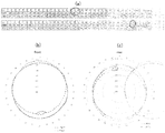
- the balance measurement result in the balance measurement method of the bicycle wheel is shown, (a) is a table showing measured values, (b) is a radar chart showing the balance state.
- FIG. 1A and 1B show a balance measuring device for a bicycle wheel according to an embodiment.
- FIG. 1A is a schematic diagram showing a disassembled state
- FIG. 1B is a schematic diagram showing a measured state.
- a bicycle wheel balance measurement apparatus 100 includes a substrate 110 and a load measurement device disposed on the substrate 110, as shown in FIG.
- a digital scale 130 and an axle support member 240 for arranging a bicycle wheel 200 having a diameter D (hereinafter referred to as a wheel 200) on the substrate 110 are provided.
- the load W of the wheel 200 on the board 110 is set to the axle support member 240 in a state where the wheel 200 is attached to the axle support member 240. Supported by a digital scale 130. Then, the load W2 applied to the digital balance 130 is measured. Measurement is performed at a plurality of locations on the outer periphery of the wheel 200, and a load distribution state at each measurement location is acquired. Based on this value, the balance state of the wheel 200 is obtained, and the weight of the correction weight to be attached to the wheel 200 and the attachment position to the wheel 200 are obtained from this balance state. Further, after the correction weight is attached, balance measurement is performed by the measuring apparatus 100, and this is repeated as necessary.
- the substrate 110 includes a flat plate member 111 and a support member 120 that is disposed on the plate member 111 and on which the axle support member 240 is disposed. Reinforcing members 112 and 113 are joined to the lower surface of the plate member 111.
- the support member 120 has recesses 122, 123, and 124 cut out at three locations. Thereby, since the arrangement position of the axle support member 240 can be changed,
- the axle support member 240 includes a flat plate-like fixed plate portion 241 attached to one end (in this example, the lower end) of the hub 210, and an extended plate portion 242 extending in an orthogonal direction from the end edge portion of the fixed plate portion 241.
- This is a channel-like member having a substantially L-shaped cross section and having a predetermined length as shown in FIG.
- the dimension “a” of the fixed plate portion 241 is made larger than the dimension “b” of the extended plate portion 242.
- the length of the axle support member 240 in the length direction (the depth direction in FIG. 1) is formed to be substantially the same as the width dimension H of the plate member 111.
- the one end side of the hub 210 can be detachably attached to the fixed plate portion 241 of the axle support member 240 in a state where the wheel 200 is rotatable. Further, a linear fulcrum portion 243 that protrudes in the direction opposite to the axle when the hub 210 is attached and that can rotatably support the bicycle axle is formed at the distal end of the extended plate portion 242. Yes. At the time of measurement, the fulcrum part 243 is disposed in any one of the recesses 122, 123, and 124 of the support member 120.
- the wheel 200 that performs balance measurement is of a quick release type and includes a hub 210, a spoke 220, a rim 231, and a tire 232.
- An axle 212 to which a quick release lever 213 is connected is rotatably disposed on a hollow hub shaft 211 of the hub 210, and an adjustment nut 214 is disposed on the opposite side of the quick release lever 213.
- the mechanism using the quick release lever 213 is used as an axle fixing member that fixes one end of the axle to the axle support member 240.
- the quick release type wheel is configured so that the wheel can be quickly attached to and detached from the fork or chain stay without using a tool.
- Some bicycle wheels are provided with lock nuts at both ends of the hub. These types of wheels can be measured in the same way.
- FIG. 2A and 2B show a substrate 110 of the bicycle wheel balance measuring device, wherein FIG. 2A is a front view, FIG. 2B is a plan view, FIG. 3C is a right side view, and FIG. 3 is a balance of the bicycle wheel. It is a perspective view which shows the board
- a digital scale 130 is arranged on the substrate 110.
- the substrate 110 is made of wood.
- the substrate 110 includes a flat plate member 111, two support members 120 that are swingably held on the upper surface about the fulcrum portion 243 of the axle support member 240, and reinforcing members 112 and 113.
- the support member 120 is disposed at both ends in the width direction on one end side in the length direction of the plate member 111.
- the two support members 120 are each formed by forming three recesses 122, 123, and 124 each having a triangular shape in a side section with a hypotenuse on the upper surface of a wooden quadrangular prism member 121.
- the recesses 122, 123, and 124 are formed in a shape that does not cause resistance to swinging of the fulcrum part 243 of the axle support member 240 to be installed.
- the recessed parts 122, 123, and 124 select the installation position so that the arrangement position of the axle support member 240 to which the wheel 200 is attached can be selected according to the size of the wheel 200 to be measured.
- the number of recesses is not limited to three, and the number can be set as necessary.
- the fulcrum portions 243 are disposed in any one of the pair of corresponding recesses 122, 123, and 124 of the two support members 120.
- the wheel 200 can freely swing along a plane including the axis of the hub 210.
- it can replace with providing the supporting member 120 and can provide the convex part or recessed part which supports the fulcrum part 243 of the axle shaft support member 240.
- the two reinforcement members 112 and 113 are provided in order to reinforce the plate member 111 and to prevent rattling when the plate member 111 is disposed on the installation surface GL.
- the reinforcing members 112 and 113 are made of wooden square pillar members.
- the plate member 111, the support member 120, and the reinforcing members 112 and 113 constituting the substrate 110 are made of wood, but can be formed of metal, synthetic resin, or the like.
- substrate 110 should just be provided with the plate member 111 and the supporting member 120 at least. Furthermore, these parts can be integrally formed.
- the digital scale 130 electrically measures the mass of the object to be measured based on the displacement voltage of the piezoelectric element or the like.
- a commercially available electronic type having a weighing weight of 1 kg and a minimum scale of 1 g was used.
- a scale stand 132, a liquid crystal display unit 133, and a switch 134 are arranged on the upper surface of the main body 131 of the digital scale 130. Note that the weight and the minimum scale value of the digital scale 130 can be selected according to the weight of the wheel 200 to be measured.
- the load W applied to the center of gravity G of the wheel 200 is applied as a load W1 at the fulcrum 243 and as a load W2 at the digital balance 130.
- the load W1 and the load W2 are determined by the size of the wheel 200 (diameter D) and the size of the axle support member 240 if the center of gravity G of the wheel 200 is on the axis of the hub 210.
- the values of L1 and L2 are determined by the diameter D of the wheel 200, the dimension a and dimension b of the axle support member 240, and the dimension h of the hub 210.
- the value of the load W2 is the same regardless of the position on the outer periphery of the wheel 200.
- the center of gravity G is shifted from the axis of the hub 210.
- the value of W1 / W2 varies depending on the length dimension h of the hub 210, but is smaller than 4/1. can do.
- the load W by a general wheel is about 1000 to 2000 g
- the load W2 is about 100 to 200 g.
- the weighing of the digital balance 130 is sufficient if it is 1000 g.
- the mass of the modified weight required for balancing the bicycle wheel is generally considered to be about 15 g in units of 0.5 g. Therefore, if a 4 g correction weight is attached, the mass of the correction weight is 4% when the measured value of the digital balance 130 is 100 g, and the accuracy is sufficiently high even when the sensitivity of the digital balance 130 is taken into consideration. For this reason, a minimum scale of 1 g is sufficient.
- the corrected weight is 0.5% of the measured value 800 g of the digital scale 130.
- the accuracy of the digital scale is questionable considering the sensitivity of the digital scale.
- it is comprised so that the value of the load W2 may be made as small as possible.
- the digital scale 130 is not limited to the above example. In order to perform more precise balance measurement and correction, a digital scale with a finer minimum scale is used.
- FIG. 4A and 4B show an axle support member of the bicycle wheel balance measuring device, wherein FIG. 4A is a side view, FIG. 4B is a plan view, FIG. 4C is a bottom view, and FIG. FIG. 5 is a rear view, and FIG. 5 is a perspective view showing an axle support member of the bicycle wheel balance measuring apparatus.
- the axle support member 240 is formed in a channel shape having a predetermined length as a whole, and is configured by overlapping and joining two aluminum L-shaped extrusion members having different lengths. . That is, the first member 250 (dimension m1: see FIG. 6A) and the second member 260 (dimension m2: see FIG. 6A) are overlapped to form.
- the length dimension m1 of the first member 250 is formed larger than the length dimension m2 of the second member 260.
- FIG. 1 of the first member 250 is formed substantially the same as the width dimension H of the plate member 111 (see FIG. 2B).
- the thickness dimension of the axle support member 240 that is, the thickness d (see FIG. 4A) in which the first member 250 and the second member 260 are overlapped, is attached to the fork or chain stay attachment part to which the wheel 200 is attached. It is desirable to be equal to the thickness dimension. In this way, the wheel 200 can be easily installed on the axle support member 240.
- the first member 250 includes two orthogonal first plate portions 251 and a second plate portion 252 having a width dimension smaller than that of the first plate portion. At the center in the width direction of both plate portions 251 and 252, notches 253 and 254 for fitting the axles 212 of the wheels 200 are formed.
- the notches 253 and 254 have a U shape with an opening toward the outside.
- the second member 260 has a shape in which the first plate portion 261 and the second plate portion 262 having a smaller width dimension than the first plate portion 261 are orthogonal to each other.
- the notches 263 and 264 are formed at the center in the width direction of both the plate portions 261 and 262.
- the notches 263 and 264 have a U shape with an opening toward the outside. Further, the notches 263 and 264 are formed larger than the notches 253 and 254.
- the notch portion 253 and the notch portion 263 provide a notch hole portion 245 for attaching the hub 210 to the fixed plate portion 241 side, and the notch portion 254 and the notch portion 264 provide a notch for attaching the hub 210 to the extending plate portion 242 side.
- a hole 246 is formed.
- the axle support member 240 includes fulcrum portions 243 at two locations. That is, one of the end edge portion of the first plate portion 251 and the end edge portion of the second plate portion 252 constituting the first member 250 functions as the fulcrum portion 243. With such a configuration, the axle support member 240 can support the wheel 200 under different conditions corresponding to the case where the diameter and mass of the wheel 200 are different.
- the wheel 200 will be described as a type having a quick release lever 213.
- the quick release lever 213 of the wheel 200 removed from the bicycle is loosened, and the notches 253 and 263 of the axle support member 240 are inserted between the adjustment nut 214 on the opposite side of the quick release lever 213 and the hub shaft 211, and further the quick A spacer 280 is disposed between the release lever 213 and the hub shaft 211.
- the hub axle 211 of the wheel 200 can be freely rotated with respect to the axle support member 240.
- the load at 1 to 32 measurement points (spoke installation positions) set on the wheel 200 is measured by the digital balance 130, and the measurement result is recorded.
- the balance state of the wheel 200 is grasped from this measurement result.
- the spacer 280 is a member having the same thickness as that of the fork and chain stay of the fixed plate portion 241 of the axle support member 240, and the quick release lever 213 moves the wheel 200 to the axle support member 240.
- a U-shaped one having a notch for inserting the axle 212 can be used.
- a spacer 290 having a shape extending in the diametrical direction of the wheel (shown by an imaginary line in FIG. 1B) can be used.
- the reason for using such a long spacer 280 is as follows. That is, when measuring the wheel 200 having a large mass, a large load is applied to the digital balance 130. However, as described above, a smaller load on the digital scale 130 is advantageous in measuring the balance. Therefore, measurement is performed in a state where the long spacer 280 is disposed on the opposite side in the radial direction of the digital balance 130 and the wheel. Then, due to the load Ws of the spacer 290, the entire center of gravity moves to the anti-digital scale 130 side, and the load on the digital scale 130 decreases. For this reason, when measuring a large-mass wheel, balance measurement can be performed stably.
- the quick release lever 213 as an example was demonstrated as the wheel 200 here, the thing of a type which is not equipped with a quick release lever as a wheel can be made into a measuring object.
- the fixing portion 241 of the axle support member 240 is attached to the screw portion of the wheel hub, and a fixing nut as an axle fixing member is screwed into the screw portion and fixed.
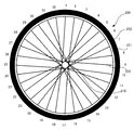
- FIG. 6 is a schematic diagram showing an example of a measurement position of a bicycle wheel in the bicycle wheel balance measurement method
- FIG. 7 shows a balance measurement result in the bicycle wheel balance measurement method. Is a table showing measured values
- (b) is a radar chart showing a balanced state.
- a joint location to the rim 231 of 32 spokes 220 arranged on the wheel 200 is set as a measurement location. Note that an air valve is attached to the position of the number “1”. The measurement is performed on the front wheel (rear) and the rear wheel (rear), and the mass is 1100 g for the front wheel, 1600 g for the rear wheel, and the diameter is 700 mm.
- FIGS. 7 (a) and 7 (b) The measurement results of the front wheels are shown in FIGS. 7 (a) and 7 (b). Based on the radar chart of FIG. 7 (b), which is 230g to 239g, the difference is 9g, and the average is 235g at the measurement points "1" to "32", the "16" and “17” of the rim 231 A 4.5-g adjusting weight was attached to the space in between. The mass of the counterweight is determined by 1/2 of the difference
- the measurement results of the rear wheels are shown in FIGS. 7 (a) and 7 (c).
- the measurement points 1 to 32 were 304 g to 327 g, the difference was 23 g, and the average was 316 g.
- the rear wheel is heavier than the front wheel because the sprocket is attached.
- the mass of the counterweight is determined by 1/2 of the difference.
- the bicycle wheel balance measuring apparatus As described above, according to the bicycle wheel balance measuring apparatus according to the present invention, it is possible to easily and accurately measure the balance of the bicycle wheel without using a large-scale device.
- Balance measuring device (Bicycle wheel balance measuring device) 110: Substrate 111: Plate member 112, 113: Reinforcement member 120: Support member 121: Square column member 122, 123, 124: Recess 130: Digital scale (load measuring device) 131: Main body 132: Scale stand 133: Liquid crystal display unit 134: Switch 200: Wheel (wheel for bicycle) 210: Hub 211: Hub shaft 212: Axle 213: Quick release lever 214: Adjustment nut 220: Spoke 231: Rim 232: Tire 240: Axle support member 241: Fixed plate portion 242: Extension plate portion 243: Support portion 245 246: Notch hole portion 250: First member 251: First plate portion 252: Second plate portion 253, 254: Notch portion 260: Second member 261: First plate portion 262: Second plate portion 263, 264: Notch 253, 263: Notch 263, 264: Notch 280: Spacer 290: Spacer
Landscapes
- Engineering & Computer Science (AREA)
- Physics & Mathematics (AREA)
- Aviation & Aerospace Engineering (AREA)
- General Physics & Mathematics (AREA)
- General Engineering & Computer Science (AREA)
- Acoustics & Sound (AREA)
- Mechanical Engineering (AREA)
- Testing Of Balance (AREA)
Applications Claiming Priority (2)
| Application Number | Priority Date | Filing Date | Title |
|---|---|---|---|
| JP2012004342U JP3179104U (ja) | 2012-07-17 | 2012-07-17 | 自転車用車輪のつり合い測定装置 |
| JP2012-004342U | 2012-07-17 |
Publications (1)
| Publication Number | Publication Date |
|---|---|
| WO2014013532A1 true WO2014013532A1 (fr) | 2014-01-23 |
Family
ID=48005796
Family Applications (1)
| Application Number | Title | Priority Date | Filing Date |
|---|---|---|---|
| PCT/JP2012/008192 Ceased WO2014013532A1 (fr) | 2012-07-17 | 2012-12-21 | Dispositif de mesure d'équilibre pour roue de vélo |
Country Status (2)
| Country | Link |
|---|---|
| JP (1) | JP3179104U (fr) |
| WO (1) | WO2014013532A1 (fr) |
Citations (6)
| Publication number | Priority date | Publication date | Assignee | Title |
|---|---|---|---|---|
| JPS5389102A (en) * | 1976-09-17 | 1978-08-05 | Holland Mechanics Bv | Apparatus for detecting nonnalignment of rim of spark wheel |
| JPS586436A (ja) * | 1981-07-03 | 1983-01-14 | Jitensha Sangyo Shinko Kyokai | 自転車の車輪疲れ試験機 |
| JPS616003A (ja) * | 1984-06-19 | 1986-01-11 | Bridgestone Cycle Co | スポ−ク車輪の不整合検出修正装置 |
| JPS6112402A (ja) * | 1984-06-28 | 1986-01-20 | Bridgestone Cycle Co | スポ−ク車輪の不整合検出修正装置のスポ−ク車輪駆動装置 |
| JPH11160183A (ja) * | 1997-11-28 | 1999-06-18 | Shinko Electric Co Ltd | 静的バランス測定装置 |
| WO2002066949A1 (fr) * | 2001-02-20 | 2002-08-29 | Bridgestone Corporation | Procede et dispositif d'ajustement d'une equilibreuse de roues |
-
2012
- 2012-07-17 JP JP2012004342U patent/JP3179104U/ja not_active Expired - Fee Related
- 2012-12-21 WO PCT/JP2012/008192 patent/WO2014013532A1/fr not_active Ceased
Patent Citations (6)
| Publication number | Priority date | Publication date | Assignee | Title |
|---|---|---|---|---|
| JPS5389102A (en) * | 1976-09-17 | 1978-08-05 | Holland Mechanics Bv | Apparatus for detecting nonnalignment of rim of spark wheel |
| JPS586436A (ja) * | 1981-07-03 | 1983-01-14 | Jitensha Sangyo Shinko Kyokai | 自転車の車輪疲れ試験機 |
| JPS616003A (ja) * | 1984-06-19 | 1986-01-11 | Bridgestone Cycle Co | スポ−ク車輪の不整合検出修正装置 |
| JPS6112402A (ja) * | 1984-06-28 | 1986-01-20 | Bridgestone Cycle Co | スポ−ク車輪の不整合検出修正装置のスポ−ク車輪駆動装置 |
| JPH11160183A (ja) * | 1997-11-28 | 1999-06-18 | Shinko Electric Co Ltd | 静的バランス測定装置 |
| WO2002066949A1 (fr) * | 2001-02-20 | 2002-08-29 | Bridgestone Corporation | Procede et dispositif d'ajustement d'une equilibreuse de roues |
Also Published As
| Publication number | Publication date |
|---|---|
| JP3179104U (ja) | 2012-10-18 |
Similar Documents
| Publication | Publication Date | Title |
|---|---|---|
| US11982586B2 (en) | Method for measuring imbalance forces of a tire/hub assembly of vehicle during motion of the vehicle | |
| EP2822820B1 (fr) | Coupleur pour roue électrique intelligente pour vélos électriques | |
| JP2014521105A (ja) | トルクセンサ | |
| ES2561221T3 (es) | Dispositivo para medir las fuerzas generadas por un desequilibrio | |
| US9417157B2 (en) | Wheel balancing machine with a tire removing device | |
| JP2014219268A (ja) | ブッシュ分力検出装置 | |
| JP2019535570A (ja) | フォニックホイール速度センサ支持構造体を備えたオートバイ | |
| JP3179104U (ja) | 自転車用車輪のつり合い測定装置 | |
| US8899111B2 (en) | Device for measuring forces generated by an unbalance | |
| CN1936530A (zh) | 用于平衡车轮的机器 | |
| JP2013040801A (ja) | 自転車の車輪組の動態平衡校正及び重量調整装置 | |
| JP3187832U (ja) | 自転車用車輪のつり合い測定装置 | |
| JPS633250B2 (fr) | ||
| JP4844020B2 (ja) | ホイールの分力計測装置 | |
| JP2007147345A (ja) | シャーシダイナモメータの検量装置 | |
| US4290205A (en) | Rim surface measuring guage for wheel balances | |
| JP2019198574A (ja) | 車椅子用車輪、車椅子および車椅子の走行状況計測システム | |
| JP4022455B2 (ja) | 釣合試験機 | |
| JP5056422B2 (ja) | シャシーダイナモメータにおける荷重測定部の検量装置 | |
| JP5603910B2 (ja) | タイヤ組付体のバランス修正方法 | |
| KR101653219B1 (ko) | 차량 휘일 캠버 조정 지그 | |
| EP4182653B1 (fr) | Équilibreur de roue statique | |
| JP3189692U (ja) | 自転車の車輪組の動態平衡校正及び重量調整装置 | |
| EP1639336A1 (fr) | Appareil et procede pour l'equilibrage statique des roues d'un vehicule | |
| JP3156813U (ja) | 自転車の車軸用ペグユニット |
Legal Events
| Date | Code | Title | Description |
|---|---|---|---|
| 121 | Ep: the epo has been informed by wipo that ep was designated in this application |
Ref document number: 12881449 Country of ref document: EP Kind code of ref document: A1 |
|
| NENP | Non-entry into the national phase |
Ref country code: DE |
|
| 122 | Ep: pct application non-entry in european phase |
Ref document number: 12881449 Country of ref document: EP Kind code of ref document: A1 |