WO2014013594A1 - Instrument d'administration de liquide - Google Patents
Instrument d'administration de liquide Download PDFInfo
- Publication number
- WO2014013594A1 WO2014013594A1 PCT/JP2012/068367 JP2012068367W WO2014013594A1 WO 2014013594 A1 WO2014013594 A1 WO 2014013594A1 JP 2012068367 W JP2012068367 W JP 2012068367W WO 2014013594 A1 WO2014013594 A1 WO 2014013594A1
- Authority
- WO
- WIPO (PCT)
- Prior art keywords
- rail
- cover member
- liquid
- groove
- administration device
- Prior art date
- Legal status (The legal status is an assumption and is not a legal conclusion. Google has not performed a legal analysis and makes no representation as to the accuracy of the status listed.)
- Ceased
Links
Images


Classifications
-
- A—HUMAN NECESSITIES
- A61—MEDICAL OR VETERINARY SCIENCE; HYGIENE
- A61M—DEVICES FOR INTRODUCING MEDIA INTO, OR ONTO, THE BODY; DEVICES FOR TRANSDUCING BODY MEDIA OR FOR TAKING MEDIA FROM THE BODY; DEVICES FOR PRODUCING OR ENDING SLEEP OR STUPOR
- A61M5/00—Devices for bringing media into the body in a subcutaneous, intra-vascular or intramuscular way; Accessories therefor, e.g. filling or cleaning devices, arm-rests
- A61M5/178—Syringes
- A61M5/31—Details
- A61M5/32—Needles; Details of needles pertaining to their connection with syringe or hub; Accessories for bringing the needle into, or holding the needle on, the body; Devices for protection of needles
- A61M5/3205—Apparatus for removing or disposing of used needles or syringes, e.g. containers; Means for protection against accidental injuries from used needles
- A61M5/321—Means for protection against accidental injuries by used needles
- A61M5/3216—Caps placed transversally onto the needle, e.g. pivotally attached to the needle base
-
- A—HUMAN NECESSITIES
- A61—MEDICAL OR VETERINARY SCIENCE; HYGIENE
- A61M—DEVICES FOR INTRODUCING MEDIA INTO, OR ONTO, THE BODY; DEVICES FOR TRANSDUCING BODY MEDIA OR FOR TAKING MEDIA FROM THE BODY; DEVICES FOR PRODUCING OR ENDING SLEEP OR STUPOR
- A61M5/00—Devices for bringing media into the body in a subcutaneous, intra-vascular or intramuscular way; Accessories therefor, e.g. filling or cleaning devices, arm-rests
- A61M5/178—Syringes
- A61M5/31—Details
- A61M5/315—Pistons; Piston-rods; Guiding, blocking or restricting the movement of the rod or piston; Appliances on the rod for facilitating dosing ; Dosing mechanisms
-
- A—HUMAN NECESSITIES
- A61—MEDICAL OR VETERINARY SCIENCE; HYGIENE
- A61M—DEVICES FOR INTRODUCING MEDIA INTO, OR ONTO, THE BODY; DEVICES FOR TRANSDUCING BODY MEDIA OR FOR TAKING MEDIA FROM THE BODY; DEVICES FOR PRODUCING OR ENDING SLEEP OR STUPOR
- A61M5/00—Devices for bringing media into the body in a subcutaneous, intra-vascular or intramuscular way; Accessories therefor, e.g. filling or cleaning devices, arm-rests
- A61M5/178—Syringes
- A61M5/28—Syringe ampoules or carpules, i.e. ampoules or carpules provided with a needle
- A61M5/285—Syringe ampoules or carpules, i.e. ampoules or carpules provided with a needle with sealing means to be broken or opened
- A61M5/288—Syringe ampoules or carpules, i.e. ampoules or carpules provided with a needle with sealing means to be broken or opened by piercing without internal pressure increase
-
- A—HUMAN NECESSITIES
- A61—MEDICAL OR VETERINARY SCIENCE; HYGIENE
- A61M—DEVICES FOR INTRODUCING MEDIA INTO, OR ONTO, THE BODY; DEVICES FOR TRANSDUCING BODY MEDIA OR FOR TAKING MEDIA FROM THE BODY; DEVICES FOR PRODUCING OR ENDING SLEEP OR STUPOR
- A61M5/00—Devices for bringing media into the body in a subcutaneous, intra-vascular or intramuscular way; Accessories therefor, e.g. filling or cleaning devices, arm-rests
- A61M5/178—Syringes
- A61M5/31—Details
- A61M5/32—Needles; Details of needles pertaining to their connection with syringe or hub; Accessories for bringing the needle into, or holding the needle on, the body; Devices for protection of needles
- A61M5/3205—Apparatus for removing or disposing of used needles or syringes, e.g. containers; Means for protection against accidental injuries from used needles
- A61M5/321—Means for protection against accidental injuries by used needles
- A61M5/3243—Means for protection against accidental injuries by used needles being axially-extensible, e.g. protective sleeves coaxially slidable on the syringe barrel
- A61M5/326—Fully automatic sleeve extension, i.e. in which triggering of the sleeve does not require a deliberate action by the user
-
- A—HUMAN NECESSITIES
- A61—MEDICAL OR VETERINARY SCIENCE; HYGIENE
- A61M—DEVICES FOR INTRODUCING MEDIA INTO, OR ONTO, THE BODY; DEVICES FOR TRANSDUCING BODY MEDIA OR FOR TAKING MEDIA FROM THE BODY; DEVICES FOR PRODUCING OR ENDING SLEEP OR STUPOR
- A61M5/00—Devices for bringing media into the body in a subcutaneous, intra-vascular or intramuscular way; Accessories therefor, e.g. filling or cleaning devices, arm-rests
- A61M5/178—Syringes
- A61M5/31—Details
- A61M5/32—Needles; Details of needles pertaining to their connection with syringe or hub; Accessories for bringing the needle into, or holding the needle on, the body; Devices for protection of needles
- A61M5/3205—Apparatus for removing or disposing of used needles or syringes, e.g. containers; Means for protection against accidental injuries from used needles
- A61M5/321—Means for protection against accidental injuries by used needles
- A61M5/3243—Means for protection against accidental injuries by used needles being axially-extensible, e.g. protective sleeves coaxially slidable on the syringe barrel
- A61M5/3271—Means for protection against accidental injuries by used needles being axially-extensible, e.g. protective sleeves coaxially slidable on the syringe barrel with guiding tracks for controlled sliding of needle protective sleeve from needle exposing to needle covering position
- A61M5/3272—Means for protection against accidental injuries by used needles being axially-extensible, e.g. protective sleeves coaxially slidable on the syringe barrel with guiding tracks for controlled sliding of needle protective sleeve from needle exposing to needle covering position having projections following labyrinth paths
-
- A—HUMAN NECESSITIES
- A61—MEDICAL OR VETERINARY SCIENCE; HYGIENE
- A61M—DEVICES FOR INTRODUCING MEDIA INTO, OR ONTO, THE BODY; DEVICES FOR TRANSDUCING BODY MEDIA OR FOR TAKING MEDIA FROM THE BODY; DEVICES FOR PRODUCING OR ENDING SLEEP OR STUPOR
- A61M5/00—Devices for bringing media into the body in a subcutaneous, intra-vascular or intramuscular way; Accessories therefor, e.g. filling or cleaning devices, arm-rests
- A61M5/178—Syringes
- A61M5/31—Details
- A61M5/315—Pistons; Piston-rods; Guiding, blocking or restricting the movement of the rod or piston; Appliances on the rod for facilitating dosing ; Dosing mechanisms
- A61M5/31501—Means for blocking or restricting the movement of the rod or piston
- A61M2005/31508—Means for blocking or restricting the movement of the rod or piston provided on the piston-rod
-
- A—HUMAN NECESSITIES
- A61—MEDICAL OR VETERINARY SCIENCE; HYGIENE
- A61M—DEVICES FOR INTRODUCING MEDIA INTO, OR ONTO, THE BODY; DEVICES FOR TRANSDUCING BODY MEDIA OR FOR TAKING MEDIA FROM THE BODY; DEVICES FOR PRODUCING OR ENDING SLEEP OR STUPOR
- A61M5/00—Devices for bringing media into the body in a subcutaneous, intra-vascular or intramuscular way; Accessories therefor, e.g. filling or cleaning devices, arm-rests
- A61M5/178—Syringes
- A61M5/31—Details
- A61M5/32—Needles; Details of needles pertaining to their connection with syringe or hub; Accessories for bringing the needle into, or holding the needle on, the body; Devices for protection of needles
- A61M5/3205—Apparatus for removing or disposing of used needles or syringes, e.g. containers; Means for protection against accidental injuries from used needles
- A61M5/321—Means for protection against accidental injuries by used needles
- A61M5/3243—Means for protection against accidental injuries by used needles being axially-extensible, e.g. protective sleeves coaxially slidable on the syringe barrel
- A61M5/326—Fully automatic sleeve extension, i.e. in which triggering of the sleeve does not require a deliberate action by the user
- A61M2005/3267—Biased sleeves where the needle is uncovered by insertion of the needle into a patient's body
-
- A—HUMAN NECESSITIES
- A61—MEDICAL OR VETERINARY SCIENCE; HYGIENE
- A61M—DEVICES FOR INTRODUCING MEDIA INTO, OR ONTO, THE BODY; DEVICES FOR TRANSDUCING BODY MEDIA OR FOR TAKING MEDIA FROM THE BODY; DEVICES FOR PRODUCING OR ENDING SLEEP OR STUPOR
- A61M5/00—Devices for bringing media into the body in a subcutaneous, intra-vascular or intramuscular way; Accessories therefor, e.g. filling or cleaning devices, arm-rests
- A61M5/178—Syringes
- A61M5/31—Details
- A61M5/32—Needles; Details of needles pertaining to their connection with syringe or hub; Accessories for bringing the needle into, or holding the needle on, the body; Devices for protection of needles
- A61M5/3287—Accessories for bringing the needle into the body; Automatic needle insertion
Definitions
- the present invention relates to a liquid administration device.
- a prefilled syringe in which a liquid preparation is filled aseptically and the liquid preparation can be administered (see, for example, Patent Document 1).
- the prefilled syringe described in Patent Document 1 is filled in a space surrounded by a syringe outer cylinder having a mouth portion for discharging a liquid preparation, a gasket that can slide in the syringe outer cylinder, and the syringe outer cylinder and the gasket.
- a plunger that is connected to the proximal end of the gasket and that discharges the liquid preparation from the mouth by pressing the gasket toward the distal end.
- this prefilled syringe is an unused state, and the mouth part of the syringe outer cylinder is liquid-tightly sealed with a cap.
- a cap is removed from the mouth part of a syringe outer cylinder, and an injection needle is attached to the mouth part from which the cap is removed.
- the living body is punctured with the injection needle, and the plunger is pressed in this punctured state.
- a liquid formulation will be discharged from a mouth part with a gasket, Therefore The said liquid formulation can be administered to a biological body via an injection needle.
- the prefilled syringe can normally press the plunger at any timing of the user if the cap is removed, the plunger is erroneously pressed before the living body is punctured with the injection needle. There was a risk of problems. In this case, the liquid preparation leaked unintentionally from the injection needle, or the amount of the liquid preparation was insufficient, and it was difficult to administer a sufficient amount of the liquid preparation to the living body.
- An object of the present invention is to provide a liquid administration device that can reliably prevent an operation member from operating erroneously.
- a cylindrical body having a cylindrical shape and filled with liquid A needle tube having a sharp needle tip at the tip, provided on the tip side of the tube, in communication with the cylinder, or provided to be able to communicate with the tube, A gasket that can slide in the cylinder; An operation member that performs a pressing operation of pressing the gasket toward the distal direction to discharge the liquid from the needle tube; A regulating member that is arranged on the outer peripheral side of the cylindrical body and that can regulate the pressing operation; A first member that covers at least the needle tip of the needle tube, and a cover member that is movable in a proximal direction from the first position to the second position where the needle tip is exposed.
- One member of the operation member and the regulating member is provided with a slider portion, and the other member is provided with a rail portion on which the slider portion slides.
- a vertical rail formed in the same direction as the operation direction at the time of operation, and a horizontal rail continuous to the vertical rail and formed in a direction perpendicular to the operation direction,
- the restricting member has a cylindrical shape
- the operating member has a plunger having a columnar shape arranged concentrically with the regulating member inside the regulating member,
- the slider portion is disposed along the circumferential direction of the inner peripheral portion of the restricting member, and the rail portion is disposed on the outer peripheral portion of the plunger so as to correspond to each slider portion.
- the restriction member has a cylindrical shape
- the cover member has a cylindrical shape arranged concentrically with the regulating member on the outside of the regulating member,
- One of the outer peripheral portion of the restricting member and the inner peripheral portion of the cover member is provided with an outer slider portion positioned outside the slider portion, and the other is an outer rail on which the outer slider portion slides.
- a portion is provided, and the outer rail portion has an outer inclined rail formed in a direction inclined with respect to the operation direction, In the process in which the cover member moves from the first position to the second position, the outer slider portion slides on the outer inclined rail, whereby the regulating member rotates about its axis,
- the liquid administration device according to (1) or (2), wherein the slider portion slides on the vertical rail from the horizontal rail, thereby enabling the pressing operation.
- the cover member is further movable to a third position that covers the needle tip and is prevented from moving to the second position; Any of the above (1) to (3), wherein the restriction member is configured to allow the cover member to move from the second position to the third position in conjunction with completion of the pressing operation.
- the outer rail portion is continuous with a base end portion of the outer inclined rail, and is formed with a first outer longitudinal rail formed in the same direction as the operation direction during the pressing operation, and a distal end of the outer inclined rail.
- An outer lateral rail formed in a direction perpendicular to the operation direction and a second outer surface formed in a direction opposite to the operation direction during the pressing operation.
- a longitudinal rail In the process in which the cover member moves from the first position to the second position, the outer slider portion slides on the first outer vertical rail and the outer inclined rail in order, and the cover member When in the second position, the outer slider portion slides on the outer lateral rail, and when the cover member moves from the second position to the third position, the outer slider portion is second.
- the liquid administration device according to (4) wherein the liquid administration device moves on the outer longitudinal rail.
- the outer rail portion engages with the outer slider portion from the tip side when the cover member moves to the third position, so that the cover member is moved to the second position again.
- the liquid administration device according to the above (5) which has an engagement part that regulates movement.
- FIG. 1 is a side view (a partially cutaway view) sequentially illustrating an operating state when the liquid administration device of the present invention is used.
- FIG. 2 is a side view (a partially cutaway view) sequentially illustrating the operating state when the liquid administration device of the present invention is used.
- FIG. 3 is a side view (a partially cutaway view) sequentially illustrating the operating state when the liquid administration device of the present invention is used.
- FIG. 4 is a side view (a partially cutaway view) sequentially illustrating the operating state when the liquid administration device of the present invention is used.
- FIG. 5 is a side view (a partially cutaway view) sequentially illustrating an operating state when the liquid administration device of the present invention is used.
- FIG. 6 is a side view (a partially cutaway view) sequentially illustrating the operating state when the liquid administration device of the present invention is used.
- FIG. 7 is a side view (a partially cutaway view) sequentially illustrating the operating state when the liquid administration device of the present invention is used.
- FIG. 8 is a longitudinal sectional view of the liquid administration device in the state shown in FIG.
- FIG. 11 is a longitudinal sectional view of the liquid administration device in the state shown in FIG. 12 is a longitudinal sectional view of the liquid administration device in the state shown in FIG.
- FIG. 13 is a longitudinal sectional view of the liquid administration device in the state shown in FIG. 14 is a longitudinal sectional view of the liquid administration device in the state shown in FIG.
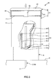
- FIG. 15 is an exploded perspective view showing the positional relationship between the operation member and the regulating member provided in the liquid administration device of the present invention.
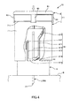
- FIG. 16 is an exploded perspective view showing the positional relationship between the regulating member and the cover member provided in the liquid administration device of the present invention.
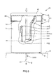
- FIG. 17 is a view of the regulating member provided in the liquid administration device of the present invention as viewed from the distal end side.
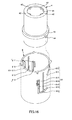
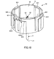
- FIG. 18 is a perspective view showing a puncture needle provided in the liquid administration device of the present invention.
- FIGS. 1 to 7 are side views sequentially showing operating states of the liquid administration device of the present invention in use (parts are cut away), and FIGS. 8 to 14 are FIGS. 1 to 7, respectively.
- FIG. 15 is an exploded perspective view showing the positional relationship between the operation member and the regulating member provided in the liquid administration device of the present invention
- FIG. 16 is provided in the liquid administration device of the present invention.
- 17 is an exploded perspective view showing the positional relationship between the regulating member and the cover member
- FIG. 17 is a view of the regulating member provided in the liquid administration device of the present invention as viewed from the distal end side
- liquid Q is administered (injected) to a living body B.
- the liquid Q is appropriately selected according to the purpose of use.
- hematopoietic agents for example, hematopoietic agents, vaccines, hormone preparations, antirheumatic agents, anticancer agents, anesthetics, blood coagulation inhibitors, etc. Chemicals to be used.
- the liquid administration device 10 includes an inner cylinder (cylinder) 1, a puncture needle 50 composed of a double-ended needle 2 and a support member 9, a gasket 3 that can slide in the inner cylinder 1, and a proximal end of the gasket 3.
- an urging means for urging the cover member 6 an operation member 11 connected to the side, a restriction member 4 for restricting the operation of the operation member 11, a cover member 6 disposed on the outer peripheral side of the inner cylinder 1 And a coil spring 60.
- the inner cylinder 1 is composed of a member having a bottom portion 12 and a side wall 13 erected from an edge portion of the bottom portion 12, that is, a member having a bottomed cylindrical shape.
- the inner cylinder main body 14 is provided.
- the inner cylinder 1 can be filled with the liquid Q.
- the bottom portion 12 has a mortar shape, and a mouth portion 121 through which a liquid passes is formed through the center portion.
- the side wall 13 has a cylindrical shape.
- the inner cylinder 1 has a sealing member (sealing part) 15 for liquid-tightly sealing the mouth part 121 of the inner cylinder main body 14 and a fixing member 16 for fixing the sealing member 15 from the distal end side. is doing.
- the sealing member 15 is formed of a disk-shaped elastic piece, and a ring-shaped recess 151 is formed on the base end surface thereof.
- a ring-shaped convex portion 122 protruding from the mouth portion 121 of the inner cylinder main body 14 can be fitted into the concave portion 151 in a liquid-tight manner.
- the sealing member 15 can be mounted on the mouth portion 121 of the inner cylinder main body 14 and the mouth portion 121 can be sealed in a liquid-tight manner.
- the fixing member 16 is a ring-shaped member.
- the fixing member 16 is fitted to the sealing member 15 from the outer peripheral side, and the sealing member 15 is sandwiched between the fixing member 16 and the convex portion 122, whereby the sealing member 15 is attached to the inner cylinder main body 14. It can be securely fixed. Thereby, the detachment
- a fixing method of the fixing member 16 a method by adhesion or a method by welding may be used as a fixing method of the fixing member 16.
- polyvinyl chloride polyethylene, a polypropylene, cyclic polyolefin, Polystyrene such as polystyrene, poly- (4-methylpentene-1), polycarbonate, acrylic resin, acrylonitrile-butadiene-styrene copolymer, polyethylene terephthalate, polyethylene naphthalate, butadiene-styrene copolymer, polyamide (for example, nylon) 6, various types of resins such as nylon 6,6, nylon 6,10, nylon 12).
- polypropylene, cyclic polyolefin, polyester, poly- (4-methyl) are easy to mold.
- Penten-1) Fat is preferable.
- the elastic material constituting the sealing member 15 and the gasket 3 is not particularly limited.
- various rubber materials such as natural rubber, butyl rubber, isoprene rubber, butadiene rubber, styrene-butadiene rubber, silicone rubber
- elastic materials such as various thermoplastic elastomers such as polyurethane, polyester, polyamide, olefin, and styrene, and mixtures thereof.
- a puncture needle 50 is disposed on the distal end side of the inner cylinder 1.
- the puncture needle 50 is composed of a double-ended needle 2 and a support member 9.
- the double-ended needle 2 is a hollow needle tube, which has a sharp distal needle tip (needle tip) 21 at the distal end and a sharp proximal needle tip 23 at the proximal end.
- the double-ended needle 2 can puncture the living body B with the distal needle tip 21 and can pierce the sealing member 15 of the inner cylinder 1 with the proximal needle tip 23.
- the lumen portion (hollow portion) of the double-ended needle 2 communicates with the inner cylinder 1 in a state where the proximal needle tip 23 penetrates the sealing member 15 of the inner cylinder 1, and the liquid from the inner cylinder 1 It functions as a flow path 22 through which Q passes. Further, the liquid Q is injected into the living body B through the flow path 22 in a state where the living body B is punctured from the skin to a predetermined depth with the tip side needle tip 21.
- constituent material of the double-ended needle 2 is not particularly limited, and examples thereof include a metal material such as stainless steel, aluminum or aluminum alloy, titanium or titanium alloy.
- the double-ended needle 2 having such a configuration is attached to the inner cylinder 1 via the support member 9.
- the support member 9 supports the double-ended needle 2 so as to be movable along the central axis direction with respect to the inner cylinder 1.
- the support member 9 includes a fixed portion (support portion) 91 having a disk shape and a wall portion 92 erected from the edge of the fixed portion 91 toward the proximal direction.
- the fixing portion 91 can support and fix the double-ended needle 2 at the center thereof.
- the portion supported by the fixing portion 91 of the double-ended needle 2 is in the middle of the double-ended needle 2 in the longitudinal direction.
- the wall portion 92 is a ring-shaped portion along the edge of the fixing portion 91.
- a plurality of (four in the configuration shown in FIG. 8) engaging portions 921 projecting inward are formed on the inner peripheral portion of the base end of the wall portion 92.
- the engaging portions 921 are arranged at equal intervals along the circumferential direction of the wall portion 92.
- Each engaging portion 921 is a first engaging portion 123 or a second engaging portion that is formed by being recessed in the edge portion of the bottom portion 12 of the inner cylinder 1 according to the position of the puncture needle 50 with respect to the inner cylinder 1.
- the puncture needle 50 is inserted into the inner cylinder 1 in any state where each engaging portion 921 engages with the first engaging portion 123 and each engaging portion 921 engages with each engaging portion 921. It is prevented from detaching from the tip portion of the.
- the puncture needle 50 is supported by the inner cylinder 1 via the support member 9 so as to be movable along the central axis direction.
- the puncture needle 50 has the proximal end needle tip 23 separated from the sealing member 15 of the inner cylinder 1 (or is not pierced and partitioned) as shown in FIGS. 11 to 14 can be taken, with the sealing member 15 being pierced. Therefore, unintentional leakage of the liquid Q from the double-ended needle 2 is prevented until the piercing state is reached.
- each engaging portion 921 In the separated state, each engaging portion 921 is engaged with the first engaging portion 123, and in the piercing state, each engaging portion 921 is engaged with each engaging portion 921.
- the gasket 3 is accommodated so as to be slidable along the axial direction of the inner cylinder 1.
- the space surrounded by the gasket 3 and the inner cylinder 1 is filled with the liquid Q in advance. Then, by moving the gasket 3 toward the distal end direction, the liquid Q in the inner cylinder 1 can be pushed out from the double-ended needle 2 in a state communicating with the inner cylinder 1.
- This gasket 3 has a disk-like outer shape, and two protrusions 31 and 32 are formed on the outer periphery thereof.
- the protrusion 31 and the protrusion 32 are separated along the axial direction of the gasket 3.
- each of the protrusions 31 and 32 has a ring shape along the circumferential direction of the gasket 3, and its outer diameter is slightly larger than the inner diameter of the inner cylinder 1 in a natural state where no external force is applied. Thereby, each of the protrusions 31 and 32 can slide while being in close contact with the inner peripheral portion 133 of the side wall 13 of the inner cylinder 1. Can be improved.
- a concave portion 33 is opened on the base end surface of the gasket 3 to which the distal end portion of the plunger 82 of the operation member 11 is inserted (fitted) and connected.
- the operation member 11 is a member that performs a pressing operation (discharging operation) in which the gasket 3 is pressed toward the distal end to discharge the liquid Q from the double-ended needle 2.
- the operation member 11 includes an operation member main body 8 connected to the gasket 3 and a grip member (gripping part) 7 gripped when a pressing operation is performed.
- the operation member main body 8 includes a disk-shaped top plate 81 and a plunger 82 that is formed in a cylindrical shape on the lower surface of the top plate 81.
- each claw 83 is engaged with a rib 711 that is formed in a ring shape along the circumferential direction of the outer peripheral portion 71 of the cylindrical gripping member 7, whereby the operation member main body 8, the gripping member 7, Are fixed to each other (see FIGS. 1 to 14).
- the index finger to the little finger of one hand is hung on the outer peripheral portion 71 of the gripping member 7, and the thumb is hung on the top plate 81 of the operation member main body 8. Can be done.
- a cylindrical regulating member 4 is disposed on the outer peripheral side of the inner cylinder 1, and a cylindrical cover member 6 is formed on the outer peripheral side of the regulating member 4. Is arranged. These members are arranged concentrically. Further, the regulating member 4 is supported so as to be rotatable around its central axis with respect to the inner cylinder 1, and the cover member 6 is supported so as to be movable along the central axis direction with respect to the inner cylinder 1. .
- the cover member 6 includes a first position (see FIGS. 1, 2, 8, and 9), a second position (see FIGS. 3 to 6 and FIGS. 10 to 13), and a third position (see FIGS. 7 and 14).
- the cover member 6 can cover at least the tip side needle tip 21 of the double-ended needle 2.
- the second position moved (retracted) from the first position in the proximal direction
- the distal needle tip 21 is exposed.
- the living body B can be punctured with the tip side needle tip 21.
- at the third position moved in the distal direction from the second position at least the distal needle tip 21 of the double-ended needle 2 can be covered again, and movement to the second position is prevented.
- the cover member 6 is urged toward the direction of moving from the second position to the first position (third position) by the urging force of the coil spring 60.
- the coil spring 60 is housed in the cover member 6 in a compressed state.
- the coil spring 60 has a distal end 601 in contact with the ring-shaped distal end wall 63 of the cover member 6, and a proximal end 602 in contact with the rib 43 of the inner cylinder 1. And between these, the coil spring 60 is compressed.
- the cover member 6 can be reliably urged in the direction from the second position toward the first position.
- the tip side needle tip 21 of the puncture needle 50 can be covered with the cover member 6 before and after the liquid administration device 10 is used. Can be reliably prevented.
- the constituent material of the coil spring 60 is not particularly limited, and for example, a metal material such as stainless steel can be used.
- the restricting member 4 can take a pressing operation restricting state (see FIGS. 8 and 9) and a pressing operable state (see FIGS. 11 to 13) with respect to the operating member 11.
- the pressing operation restriction state is a state in which the pressing operation by the operation member 11 can be restricted when the cover member 6 is in the first position.
- the pressing operation enabled state is a state in which the pressing operation by the operation member 11 is enabled (allowed) when the cover member 6 moves from the first position to the second position.
- the regulating member 4 is in a first movable state (see FIGS. 1 to 3), a second movable state (see FIG. 6), and a movement restricted state (see FIG. 7) with respect to the cover member 6. And can take.
- the movable state is a state in which the cover member 6 is allowed (allowed) to move from the first position to the second position.
- the second movable state is a state that allows (allows) the cover member 6 to move from the second position to the third position in conjunction with the completion of the pressing operation.
- the movement restricting state is a state in which the cover member 6 is temporarily retracted to the second position, moved to the third position, and then moved to the second position again.
- a rib 41 formed in a ring shape protrudes from the proximal end portion of the inner peripheral portion of the regulating member 4 (one member) along the circumferential direction.
- the rib 41 is formed with a plurality (four in the present embodiment) of inner protrusions (inner follower portions) 42 that protrude toward the inside and serve as slider portions. These inner protrusions 42 are arranged at equal intervals along the circumferential direction of the rib 41 (inner peripheral part of the regulating member 4).
- a rib 43 formed in a ring shape projects along the circumferential direction of the outer peripheral portion in the axial direction.
- the rib 43 is formed with a plurality (two in the present embodiment) of outer protrusions (outer follower portions) 44 protruding outward, which serve as outer slider portions positioned outside the inner protrusion 42.
- outer protrusions 44 are arranged at equal intervals along the circumferential direction of the rib 43 (the outer peripheral portion of the regulating member 4).
- the plunger 82 (the other member) arranged concentrically with the regulating member 4 inside the regulating member 4 has an inner rail portion (inside rail) on which the inner protrusion 42 slides on the outer peripheral portion.
- the same number of inner grooves (inner cam grooves) 84 as the inner protrusions 42 are formed as rail portions.
- a plurality of these inner grooves 84 are arranged so as to correspond to the respective inner protrusions 42, and one corresponding inner protrusion 42 is inserted.
- the number of the inner protrusions 42 and the inner groove portions 84 may be one, but it is preferable that there are a plurality as in the present embodiment. Thereby, the regulating member 4 can be stably rotated.
- each inner groove 84 has the same configuration, only one inner groove 84 will be described as a representative.
- the inner groove portion 84 includes an inner vertical groove (longitudinal rail) 841, an inner horizontal groove (lateral rail) 842, and an inner inclined groove 843.
- the inner longitudinal groove 841 is formed in the same direction as the operation direction during the pressing operation by the operation member 11, that is, along the axial direction (longitudinal direction) of the plunger 82.
- the inner lateral groove 842 is formed in a direction perpendicular to the operation direction during the pressing operation, that is, along the circumferential direction of the plunger 82.
- the inner lateral groove 842 intersects the middle of the inner longitudinal groove 841 in the longitudinal direction, that is, communicates (continuously).
- the inner inclined groove 843 is formed along a direction inclined with respect to the axial direction of the plunger 82.
- the inner inclined groove 843 has a tip portion intersecting with a base end portion of the inner longitudinal groove 841.
- the inner lateral grooves 842 of the adjacent inner groove portions 84 communicate with each other, and the inner lateral grooves 842 of the four inner groove portions 84 constitute a ring-like groove as a whole.
- the inner protrusion 42 moves from the inner longitudinal groove 841 to the inner inclined groove 843 until the cover member 6 returns from the second position to the first position by the biasing force of the coil spring 60.
- the inner inclined groove 843 is advanced. Also at this time, the regulating member 4 rotates in the same direction as described above.
- the cover member 6 is formed with the same number of outer grooves (outer cam grooves) 61 as the outer protrusions 44 as outer rail parts on which the outer protrusions 44 slide.
- outer grooves outer cam grooves
- a plurality of these outer groove portions 61 are arranged so as to correspond to the respective outer protrusions 44, and one corresponding outer protrusion 44 is inserted.
- the number of the outer protrusions 44 and the outer groove portions 61 may be one, but it is preferable that there are a plurality as in the present embodiment. Thereby, coupled with the plurality of inner protrusions 42 and inner groove portions 84, the restricting member 4 can be rotated more stably.
- each outer groove portion 61 Since the configuration of each outer groove portion 61 is the same, only one outer groove portion 61 will be representatively described.
- the outer groove 61 includes a first outer vertical groove (first outer vertical rail) 611, a second outer vertical groove (second outer vertical rail) 612, a third outer vertical groove 613,
- the first outer inclined groove (outer inclined rail) 614, the second outer inclined groove 615, the outer lateral groove (outer lateral rail) 616, and the outer engaging portion 617 are configured.
- the first outer longitudinal groove 611 to the outer lateral groove 616 are through holes penetrating from the inner peripheral portion to the outer peripheral portion of the cover member 6, that is, through the wall portion of the cover member 6 having a cylindrical shape.
- the first outer longitudinal groove 611 is formed in the same direction as the operation direction during the pressing operation by the operation member 11, that is, along the axial direction of the plunger 82.
- the second outer longitudinal groove 612 is located away from the first outer longitudinal groove 611 along the circumferential direction of the plunger 82 in the direction opposite to the operation direction during the pressing operation, that is, the first It is formed in parallel with the outer longitudinal groove 611.
- the third outer longitudinal groove 613 is formed between the first outer longitudinal groove 611 and the second outer longitudinal groove 612 in a direction opposite to the operation direction during the pressing operation.
- the first outer inclined groove 614 is formed between the first outer vertical groove 611 and the third outer vertical groove 613 along a direction inclined with respect to the operation direction during the pressing operation.
- the distal end of the first outer inclined groove 614 intersects with the distal end of the third outer longitudinal groove 613, and the proximal end intersects with the distal end of the first outer longitudinal groove 611.
- the second outer inclined groove 615 is formed along the direction inclined with respect to the operation direction at the time of the pressing operation, and the distal end of the second outer inclined groove 615 intersects the base end portion of the first outer vertical groove 611.
- the outer lateral groove 616 is formed between the second outer longitudinal groove 612 and the third outer longitudinal groove 613 along a direction perpendicular to the operation direction during the pressing operation. One end of the outer lateral groove 616 intersects the base end of the second outer longitudinal groove 612, and the other end is the distal end of the third outer longitudinal groove 613 and the distal end of the first outer inclined groove 614. Intersects.
- the outer engagement portion 617 is an elastic piece formed by a part of the wall portion of the cover member 6 that defines the second outer longitudinal groove 612.
- the outer engagement portion 617 is disposed at the proximal end portion of the second outer longitudinal groove 612, and can be engaged with the outer protrusion 44 from the distal end side when the cover member 6 returns to the first position. Yes (see FIG. 7). Further, the outer engagement portion 617 formed of an elastic piece can be elastically deformed, and therefore, when the cover member 6 is moved from the second position to the third position, the outer protrusion 44 is moved. The outer engagement portion 617 can be exceeded, and thus its movement can be allowed.
- the outer protrusion 44 can move in order through the second outer inclined groove 615, the first outer longitudinal groove 611, and the first outer inclined groove 614.
- the cover member 6 is in a first movable state in which the cover member 6 can move from the first position to the second position.
- the regulating member 4 can rotate. As described above, the inner protrusion 42 can be moved from the inner lateral groove 842 to the inner longitudinal groove 841 by this rotation, so that the pressing operation is possible by the operation member 11.
- the outer protrusion 44 can move in the outer lateral groove 616. This movement is performed by the rotation of the regulating member 4, and the rotational force is generated when the inner protrusion 42 moves in the inner inclined groove 843.
- the cover member 6 enters a second movable state in which the cover member 6 can move from the second position to the third position.
- the outer groove 61 is a through hole as described above, and the outer protrusion 44 can be exposed.
- the outer protruding portion 44 and the outer engaging portion 617 engaged with the outer protruding portion 44 are covered with the gripping member 7 of the operation member 11. Accordingly, it is possible to reliably prevent the engagement between the outer protrusion 44 and the outer engagement portion 617 from being unintentionally released, and thus it is possible for the cover member 6 to reliably remain in the first position. it can.
- the cover member 6 covers the tip side needle tip 21 and prevents erroneous puncture and the like.
- the puncture needle 50 can move along the axial direction with respect to the inner cylinder 1.
- the regulating member 4 can also take the puncture needle movement regulation state which regulates the movement of the puncture needle 50 (support member 9), when the cover member 6 exists in a 1st position.
- a plurality (four in the present embodiment) of inner protrusions (second inner protrusions) 45 projecting inward are formed at the tip of the inner peripheral portion of the regulating member 4. ing. These inner protrusions 45 are arranged at equal intervals along the circumferential direction of the regulating member 4.
- step portions 922 As shown in FIG. 18, the same number of step portions 922 as the inner protrusions 45 are formed on the outer peripheral portion of the wall portion 92 of the support member 9 of the puncture needle 50. Each step portion 922 is formed so as to cause a step toward the outside in the outer peripheral portion of the wall portion 92.
- the inner protrusion 45 engages with each step 922 from the base end side (see “inner protrusion 45” indicated by a solid line in FIG. 18).
- the movement of the puncture needle 50 is restricted, and the movement of the puncture needle 50 is restricted. Therefore, the double-ended needle 2 unintentionally pierces the sealing member 15 of the inner cylinder 1 before using the liquid administration device 10. This prevents the leakage of the liquid Q from the double-ended needle 2.
- a liquid administration device 10 in an unused state (initial state) shown in FIGS. 1 and 8 is prepared.
- the cover member 6 is in the first position and covers the tip side needle tip 21 of the double-ended needle 2.
- the state where the tip side needle tip 21 is covered with the cover member 6 by the urging force of the coil spring 60 is maintained. Thereby, the erroneous puncture by the tip side needle tip 21 can be prevented reliably.
- the puncture needle 50 has the proximal end needle tip 23 of the double-ended needle 2 separated from the sealing member 15 of the inner cylinder 1 and has not yet pierced the sealing member 15.
- the state in which the proximal end needle tip 23 is separated from the sealing member 15 of the inner cylinder 1 is reliably maintained by the restricting member 4 in the puncture needle movement restricting state. Thereby, the aseptic state of the liquid Q can be maintained until the administration of the liquid Q is started.
- each inner protrusion 42 is positioned in the inner lateral groove 842 of the plunger 82 of the operation member 11, and the operation member 11 is in a pressing operation restriction state. Thereby, the pressing operation by the operating member 11 is restricted (impossible).
- each outer protrusion 44 is positioned in the second outer inclined groove 615, and is movable with respect to the cover member 6.
- each outer protrusion 44 advances through the first outer longitudinal groove 611 (see FIG. 3), and the cover member 6 Move from the puncture prevention position to the puncture possible position.
- the distal needle tip 21 of the double-ended needle 2 protrudes from the opening 631 of the distal wall 63 of the cover member 6, and the distal end needle tip 21 punctures the living body B (FIGS. 3 and 10). reference).
- the distal wall 63 of the cover member 6 starts to press the support member 9 of the puncture needle 50 toward the proximal end (see FIG. 10).
- each outer protrusion 44 advances through the first outer inclined groove 614 (see FIG. 4).
- the regulating member 4 rotates and the inner protrusion 42 moves to the inner longitudinal groove 841, and a pressing operation is possible (see FIG. 11).
- the distal end wall portion 63 of the cover member 6 further presses the support member 9 of the puncture needle 50 toward the proximal direction.
- the sealing member 15 of the inner cylinder 1 can be pierced by the proximal end needle tip 23 of the double-ended needle 2, and the double-ended needle 2 punctured with the living body B and the inner cylinder 1 communicate with each other. (See FIG. 11).
- the restricting member 4 rotates as the inner protrusion 42 advances through the inner inclined groove 843. Thereby, the outer side protrusion 44 advances the outer side horizontal groove 616, and reaches the 2nd outer side vertical groove 612 (refer FIG. 5, FIG. 6).
- the restricting member 4 can be engaged with the outer engaging portion 617 by the outer protrusion 44, and is thus in a movement restricted state with respect to the cover member 6.
- the movement of the cover member 6 to the second position again is reliably restricted, and erroneous puncture by the distal end side needle tip 21 is prevented.
- the liquid Q is administered after puncturing the living body B. That is, the liquid administration device 10 can be used reliably in the order of “puncture” and “administration”. Therefore, it is possible to reliably prevent the pressing operation for discharging the liquid Q by the operation member 11 before the living body B is punctured.
- the administration can be stopped during the administration of the liquid Q.
- the cover member 6 is urged toward the distal end by the urging force of the coil spring 60, and the outer protrusion 44 has the third outer longitudinal groove. Proceeding 613 can return to the first position.
- liquid administration device of the present invention has been described above with respect to the illustrated embodiment. However, the present invention is not limited to this, and each component constituting the liquid administration device can have any function that can exhibit the same function. Can be substituted. Moreover, arbitrary components may be added.
- the puncture needle has a needle tube that is a double-ended needle in the above-described embodiment, but is not limited thereto, and may have a needle tube in which the proximal end needle tip is omitted.
- the needle tube communicates with the inner cylinder in advance (already in an unused state).
- the inner protrusion is formed on the restriction member of the operation member and the restriction member, and the inner groove portion into which the inner protrusion is inserted is formed on the plunger of the operation member.
- An inner side protrusion part may be formed in the plunger of an operation member, and the inner side groove part may be formed in the control member.
- the outer protrusion is formed on the restriction member of the restriction member and the cover member, and the outer groove portion into which the outer protrusion is inserted is formed on the cover member.
- An outer side protrusion part may be formed in a cover member, and the outer side groove part may be formed in the control member.
- the third outer longitudinal groove can be omitted in the outer groove portion.
- the restriction member has been described as having a cylindrical shape, but the height direction of the cylinder may be short, and may be a disk shape (doughnut shape) having a hole substantially in the center. It is assumed that the “cylindrical” concept in the description of the restricting member of the book includes a disk shape.
- outer rail portion and the inner rail portion are each configured with a groove in the above embodiment, but the outer slider portion and the inner slider portion are not limited to this as long as the outer slider portion and the inner slider portion can slide along the rail.
- the outer rail portion and the inner rail portion may each be constituted by a ridge (rib) or a step.
- the liquid administration device of the present invention has a cylindrical shape, a cylindrical body filled with liquid, and a sharp distal needle tip at least at the distal end and the proximal end, and the distal end of the tubular body
- a needle tube that can communicate with the cylindrical body, a gasket that can slide within the cylindrical body, and a proximal end side of the gasket, and press the gasket toward the distal direction to discharge the liquid.
- An operation member that performs a pressing operation to be discharged from the needle tube, a regulating member that is disposed on an outer peripheral side of the cylindrical body and that can regulate the pressing operation, and a first position that covers at least the tip side needle tip of the needle tube;
- a cover member that is retracted from the first position in the proximal direction and is movable to a second position where the distal needle tip is exposed, and one of the operating member and the regulating member
- the member has an inner protrusion protruding therefrom, and the other member Is formed with an inner groove into which the inner protrusion is inserted, and the inner groove communicates with the inner vertical groove formed in the same direction as the operation direction during the pressing operation, An inner lateral groove formed in a direction perpendicular to the operation direction, and when the cover member is in the first position, the inner protrusion is positioned in the inner lateral groove, and the pressing operation is performed.
- the liquid administration device of the present invention has industrial applicability.
- Liquid administration device 1 Inner cylinder (tubular body) 12 bottom part 121 mouth part 122 convex part 123 1st engaging part 124 2nd engaging part 13 side wall 133 inner peripheral part 14 inner cylinder main body 15 sealing member (sealing part) 151 Concave portion 16 Fixing member 2 Double-ended needle 21 Tip side needle tip (needle tip) 22 Flow path 23 Proximal needle tip 3 Gasket 31, 32 Protrusion 33 Concavity 4 Restriction member 41 Rib 42 Inner protrusion (inner follower) 43 Rib 44 Outer protrusion (outer follower) 45 Inner protrusion (second inner protrusion) 6 Cover member 61 Outer groove (outer cam groove) 611 First outer longitudinal groove (first outer longitudinal rail) 612 Second outer longitudinal groove (second outer longitudinal rail) 613 Third outer longitudinal groove 614 First outer inclined groove (outer inclined rail) 615 Second outer inclined groove 616 Outer lateral groove (outer lateral rail) 617 Outer engagement portion 63 Tip wall portion 631 Opening portion 7
Landscapes
- Health & Medical Sciences (AREA)
- Engineering & Computer Science (AREA)
- Hematology (AREA)
- Anesthesiology (AREA)
- Biomedical Technology (AREA)
- Heart & Thoracic Surgery (AREA)
- Vascular Medicine (AREA)
- Life Sciences & Earth Sciences (AREA)
- Animal Behavior & Ethology (AREA)
- General Health & Medical Sciences (AREA)
- Public Health (AREA)
- Veterinary Medicine (AREA)
- Environmental & Geological Engineering (AREA)
- Infusion, Injection, And Reservoir Apparatuses (AREA)
Priority Applications (5)
| Application Number | Priority Date | Filing Date | Title |
|---|---|---|---|
| JP2014525626A JP5865498B2 (ja) | 2012-07-19 | 2012-07-19 | 液体投与具 |
| PCT/JP2012/068367 WO2014013594A1 (fr) | 2012-07-19 | 2012-07-19 | Instrument d'administration de liquide |
| CN201280074765.9A CN104470562B (zh) | 2012-07-19 | 2012-07-19 | 液体投放器具 |
| EP12881488.6A EP2875838B1 (fr) | 2012-07-19 | 2012-07-19 | Instrument d'administration de liquide |
| US14/593,090 US20150119815A1 (en) | 2012-07-19 | 2015-01-09 | Liquid administering device |
Applications Claiming Priority (1)
| Application Number | Priority Date | Filing Date | Title |
|---|---|---|---|
| PCT/JP2012/068367 WO2014013594A1 (fr) | 2012-07-19 | 2012-07-19 | Instrument d'administration de liquide |
Related Child Applications (1)
| Application Number | Title | Priority Date | Filing Date |
|---|---|---|---|
| US14/593,090 Continuation US20150119815A1 (en) | 2012-07-19 | 2015-01-09 | Liquid administering device |
Publications (1)
| Publication Number | Publication Date |
|---|---|
| WO2014013594A1 true WO2014013594A1 (fr) | 2014-01-23 |
Family
ID=49948448
Family Applications (1)
| Application Number | Title | Priority Date | Filing Date |
|---|---|---|---|
| PCT/JP2012/068367 Ceased WO2014013594A1 (fr) | 2012-07-19 | 2012-07-19 | Instrument d'administration de liquide |
Country Status (5)
| Country | Link |
|---|---|
| US (1) | US20150119815A1 (fr) |
| EP (1) | EP2875838B1 (fr) |
| JP (1) | JP5865498B2 (fr) |
| CN (1) | CN104470562B (fr) |
| WO (1) | WO2014013594A1 (fr) |
Cited By (13)
| Publication number | Priority date | Publication date | Assignee | Title |
|---|---|---|---|---|
| JP2015023978A (ja) * | 2013-07-25 | 2015-02-05 | テルモ株式会社 | 液体投与具 |
| US9950124B2 (en) | 2014-03-11 | 2018-04-24 | Terumo Kabushiki Kaisha | Liquid administration tool |
| JP2019500091A (ja) * | 2015-11-27 | 2019-01-10 | サノフィ−アベンティス・ドイチュラント・ゲゼルシャフト・ミット・ベシュレンクテル・ハフツング | 薬剤注射デバイス |
| JP2019500090A (ja) * | 2015-11-27 | 2019-01-10 | サノフィ−アベンティス・ドイチュラント・ゲゼルシャフト・ミット・ベシュレンクテル・ハフツング | 薬剤送達デバイス |
| JP2020501861A (ja) * | 2016-12-15 | 2020-01-23 | ピーケイエイ ソフトタッチ コーポレイション | 係止された分配後構成を有する皮内薬物送達デバイス |
| WO2022030457A1 (fr) * | 2020-08-05 | 2022-02-10 | 株式会社ライトニックス | Dispositif de dosage médical |
| US11484662B2 (en) | 2015-11-27 | 2022-11-01 | Sanofi-Aventis Deutschland Gmbh | Medicament injection device |
| JP2022549350A (ja) * | 2019-09-30 | 2022-11-24 | アムジエン・インコーポレーテツド | 薬物送達デバイス |
| WO2023147362A1 (fr) * | 2022-01-25 | 2023-08-03 | Regeneron Pharmaceuticals, Inc. | Système de sécurité pour dispositif d'administration de médicament |
| US11865307B2 (en) | 2015-11-27 | 2024-01-09 | Sanofi-Aventis Deutschland Gmbh | Medicament injection device |
| JP2024501680A (ja) * | 2020-12-24 | 2024-01-15 | エスエイチエル・メディカル・アーゲー | 薬剤送達デバイス |
| USD1108627S1 (en) | 2023-10-02 | 2026-01-06 | Regeneron Pharmaceuticals, Inc. | Drug-delivery device |
| USD1109322S1 (en) | 2023-10-02 | 2026-01-13 | Regeneron Pharmaceuticals, Inc. | Drug-delivery device |
Families Citing this family (5)
| Publication number | Priority date | Publication date | Assignee | Title |
|---|---|---|---|---|
| JP6262030B2 (ja) * | 2014-03-11 | 2018-01-17 | テルモ株式会社 | 液体投与具 |
| JP6262031B2 (ja) * | 2014-03-11 | 2018-01-17 | テルモ株式会社 | 液体投与具 |
| EP3429664B1 (fr) * | 2016-03-16 | 2019-12-04 | Eli Lilly and Company | Ensemble déclencheur pour dispositif d'injection automatique de médicament |
| US11033686B2 (en) * | 2016-05-18 | 2021-06-15 | Shl Medical Ag | Administration mechanism for a medicament delivery device |
| CN117281978A (zh) * | 2023-07-28 | 2023-12-26 | 梵颖(上海)生物科技有限公司 | 一种注射器保护装置及安全注射器 |
Citations (4)
| Publication number | Priority date | Publication date | Assignee | Title |
|---|---|---|---|---|
| JP2004049726A (ja) * | 2002-07-23 | 2004-02-19 | Shimizu Pharmaceutical Co Ltd | 注射器 |
| JP2005319118A (ja) | 2004-05-10 | 2005-11-17 | Terumo Corp | キャップおよびプレフィルドシリンジの製造方法 |
| WO2009013844A1 (fr) * | 2007-07-23 | 2009-01-29 | Terumo Kabushiki Kaisha | Injecteur de solution de médicament |
| JP2009095392A (ja) * | 2007-10-13 | 2009-05-07 | Iwaki:Kk | 注射針及びそれを利用した注射器 |
Family Cites Families (9)
| Publication number | Priority date | Publication date | Assignee | Title |
|---|---|---|---|---|
| WO2004047892A1 (fr) * | 2002-11-25 | 2004-06-10 | Tecpharma Licensing Ag | Dispositif d'injection pourvu d'une protection d'aiguille |
| US20050101919A1 (en) * | 2003-11-07 | 2005-05-12 | Lennart Brunnberg | Device for an injector |
| WO2009040602A1 (fr) * | 2007-09-25 | 2009-04-02 | Becton Dickinson France | Dispositif d'injection automatique équipé de moyen de désactivation rendu mobile par une protection de sécurité |
| JP5432151B2 (ja) * | 2007-09-25 | 2014-03-05 | ベクトン・ディキンソン・フランス・エス.エー.エス. | 外部ソケットに収容された自動注射器 |
| CN102612381B (zh) * | 2009-03-20 | 2015-09-09 | 安塔瑞斯制药公司 | 危险试剂注入系统 |
| WO2010126432A1 (fr) * | 2009-04-27 | 2010-11-04 | Shl Group Ab | Dispositif d'aiguille de stylo de sécurité |
| CA2788982A1 (fr) * | 2010-02-05 | 2011-08-11 | Sanofi-Aventis Deutschland Gmbh | Module medicamenteux comportant une double gaine de protection d'aiguille |
| JP6047485B2 (ja) * | 2010-07-02 | 2016-12-21 | サノフィ−アベンティス・ドイチュラント・ゲゼルシャフト・ミット・ベシュレンクテル・ハフツング | 薬剤充填済みシリンジのための安全デバイスおよび注射デバイス |
| US8496619B2 (en) * | 2011-07-15 | 2013-07-30 | Antares Pharma, Inc. | Injection device with cammed ram assembly |
-
2012
- 2012-07-19 CN CN201280074765.9A patent/CN104470562B/zh active Active
- 2012-07-19 EP EP12881488.6A patent/EP2875838B1/fr active Active
- 2012-07-19 JP JP2014525626A patent/JP5865498B2/ja active Active
- 2012-07-19 WO PCT/JP2012/068367 patent/WO2014013594A1/fr not_active Ceased
-
2015
- 2015-01-09 US US14/593,090 patent/US20150119815A1/en not_active Abandoned
Patent Citations (4)
| Publication number | Priority date | Publication date | Assignee | Title |
|---|---|---|---|---|
| JP2004049726A (ja) * | 2002-07-23 | 2004-02-19 | Shimizu Pharmaceutical Co Ltd | 注射器 |
| JP2005319118A (ja) | 2004-05-10 | 2005-11-17 | Terumo Corp | キャップおよびプレフィルドシリンジの製造方法 |
| WO2009013844A1 (fr) * | 2007-07-23 | 2009-01-29 | Terumo Kabushiki Kaisha | Injecteur de solution de médicament |
| JP2009095392A (ja) * | 2007-10-13 | 2009-05-07 | Iwaki:Kk | 注射針及びそれを利用した注射器 |
Non-Patent Citations (1)
| Title |
|---|
| See also references of EP2875838A4 |
Cited By (21)
| Publication number | Priority date | Publication date | Assignee | Title |
|---|---|---|---|---|
| JP2015023978A (ja) * | 2013-07-25 | 2015-02-05 | テルモ株式会社 | 液体投与具 |
| US9950124B2 (en) | 2014-03-11 | 2018-04-24 | Terumo Kabushiki Kaisha | Liquid administration tool |
| US12496402B2 (en) | 2015-11-27 | 2025-12-16 | Sanofi | Medicament injection device |
| JP2019500090A (ja) * | 2015-11-27 | 2019-01-10 | サノフィ−アベンティス・ドイチュラント・ゲゼルシャフト・ミット・ベシュレンクテル・ハフツング | 薬剤送達デバイス |
| JP2019500091A (ja) * | 2015-11-27 | 2019-01-10 | サノフィ−アベンティス・ドイチュラント・ゲゼルシャフト・ミット・ベシュレンクテル・ハフツング | 薬剤注射デバイス |
| US12420028B2 (en) | 2015-11-27 | 2025-09-23 | Sanofi-Aventis Deutschland Gmbh | Medicament injection device |
| US11419992B2 (en) | 2015-11-27 | 2022-08-23 | Sanofi-Aventis Deutschland Gmbh | Medicament injection device |
| US11484662B2 (en) | 2015-11-27 | 2022-11-01 | Sanofi-Aventis Deutschland Gmbh | Medicament injection device |
| US11865307B2 (en) | 2015-11-27 | 2024-01-09 | Sanofi-Aventis Deutschland Gmbh | Medicament injection device |
| US11865308B2 (en) | 2015-11-27 | 2024-01-09 | Sanofi-Aventis Deutschland Gmbh | Medicament injection device |
| JP2020501861A (ja) * | 2016-12-15 | 2020-01-23 | ピーケイエイ ソフトタッチ コーポレイション | 係止された分配後構成を有する皮内薬物送達デバイス |
| JP7246318B2 (ja) | 2016-12-15 | 2023-03-27 | ピーケイエイ ソフトタッチ コーポレイション | 係止された分配後構成を有する皮内薬物送達デバイス |
| US11865321B2 (en) | 2016-12-15 | 2024-01-09 | Pka Softtouch Corp. | Fluid delivery device |
| JP2022549350A (ja) * | 2019-09-30 | 2022-11-24 | アムジエン・インコーポレーテツド | 薬物送達デバイス |
| JP7763752B2 (ja) | 2019-09-30 | 2025-11-04 | アムジエン・インコーポレーテツド | 薬物送達デバイス |
| WO2022030457A1 (fr) * | 2020-08-05 | 2022-02-10 | 株式会社ライトニックス | Dispositif de dosage médical |
| JP7082851B1 (ja) * | 2020-08-05 | 2022-06-09 | 株式会社ライトニックス | 投与デバイス |
| JP2024501680A (ja) * | 2020-12-24 | 2024-01-15 | エスエイチエル・メディカル・アーゲー | 薬剤送達デバイス |
| WO2023147362A1 (fr) * | 2022-01-25 | 2023-08-03 | Regeneron Pharmaceuticals, Inc. | Système de sécurité pour dispositif d'administration de médicament |
| USD1108627S1 (en) | 2023-10-02 | 2026-01-06 | Regeneron Pharmaceuticals, Inc. | Drug-delivery device |
| USD1109322S1 (en) | 2023-10-02 | 2026-01-13 | Regeneron Pharmaceuticals, Inc. | Drug-delivery device |
Also Published As
| Publication number | Publication date |
|---|---|
| US20150119815A1 (en) | 2015-04-30 |
| CN104470562B (zh) | 2017-04-12 |
| JP5865498B2 (ja) | 2016-02-17 |
| EP2875838A1 (fr) | 2015-05-27 |
| EP2875838A4 (fr) | 2016-03-30 |
| CN104470562A (zh) | 2015-03-25 |
| JPWO2014013594A1 (ja) | 2016-06-30 |
| EP2875838B1 (fr) | 2017-04-19 |
Similar Documents
| Publication | Publication Date | Title |
|---|---|---|
| JP5865498B2 (ja) | 液体投与具 | |
| JP6731909B2 (ja) | 包装体および包装組立体 | |
| CN104640586B (zh) | 液体给与器 | |
| JP2012205769A (ja) | 薬剤調製用具 | |
| WO2014162551A1 (fr) | Seringue | |
| WO2014115241A1 (fr) | Instrument d'administration de liquide | |
| JP6046721B2 (ja) | 液体投与具 | |
| JP6068467B2 (ja) | 医薬品容器 | |
| JP6360470B2 (ja) | 液体投与具 | |
| JP6125187B2 (ja) | 液体投与具 | |
| JP6104747B2 (ja) | 液体投与具 | |
| JP6215550B2 (ja) | 液体投与具 | |
| JP5897125B2 (ja) | 液体投与具 | |
| JP6178306B2 (ja) | 液体投与具 | |
| JPWO2015037545A1 (ja) | 液体投与具 | |
| WO2014013547A1 (fr) | Instrument pour administration de liquide | |
| WO2013146049A1 (fr) | Dispositif d'administration de liquide | |
| JP2005211336A (ja) | 導液具収納体 | |
| JP6165131B2 (ja) | 液体投与具 |
Legal Events
| Date | Code | Title | Description |
|---|---|---|---|
| 121 | Ep: the epo has been informed by wipo that ep was designated in this application |
Ref document number: 12881488 Country of ref document: EP Kind code of ref document: A1 |
|
| ENP | Entry into the national phase |
Ref document number: 2014525626 Country of ref document: JP Kind code of ref document: A |
|
| REEP | Request for entry into the european phase |
Ref document number: 2012881488 Country of ref document: EP |
|
| WWE | Wipo information: entry into national phase |
Ref document number: 2012881488 Country of ref document: EP |
|
| NENP | Non-entry into the national phase |
Ref country code: DE |