WO2014013659A1 - 除毛器具、及び除毛器具の駆動方法 - Google Patents
除毛器具、及び除毛器具の駆動方法 Download PDFInfo
- Publication number
- WO2014013659A1 WO2014013659A1 PCT/JP2013/003205 JP2013003205W WO2014013659A1 WO 2014013659 A1 WO2014013659 A1 WO 2014013659A1 JP 2013003205 W JP2013003205 W JP 2013003205W WO 2014013659 A1 WO2014013659 A1 WO 2014013659A1
- Authority
- WO
- WIPO (PCT)
- Prior art keywords
- mover
- control
- hair removal
- power
- control method
- Prior art date
- Legal status (The legal status is an assumption and is not a legal conclusion. Google has not performed a legal analysis and makes no representation as to the accuracy of the status listed.)
- Ceased
Links
Images




Classifications
-
- H—ELECTRICITY
- H02—GENERATION; CONVERSION OR DISTRIBUTION OF ELECTRIC POWER
- H02P—CONTROL OR REGULATION OF ELECTRIC MOTORS, ELECTRIC GENERATORS OR DYNAMO-ELECTRIC CONVERTERS; CONTROLLING TRANSFORMERS, REACTORS OR CHOKE COILS
- H02P25/00—Arrangements or methods for the control of AC motors characterised by the kind of AC motor or by structural details
- H02P25/02—Arrangements or methods for the control of AC motors characterised by the kind of AC motor or by structural details characterised by the kind of motor
- H02P25/032—Reciprocating, oscillating or vibrating motors
-
- B—PERFORMING OPERATIONS; TRANSPORTING
- B26—HAND CUTTING TOOLS; CUTTING; SEVERING
- B26B—HAND-HELD CUTTING TOOLS NOT OTHERWISE PROVIDED FOR
- B26B19/00—Clippers or shavers operating with a plurality of cutting edges, e.g. hair clippers, dry shavers
- B26B19/28—Drive layout for hair clippers or dry shavers, e.g. providing for electromotive drive
- B26B19/282—Motors without a rotating central drive shaft, e.g. linear motors
-
- H—ELECTRICITY
- H02—GENERATION; CONVERSION OR DISTRIBUTION OF ELECTRIC POWER
- H02K—DYNAMO-ELECTRIC MACHINES
- H02K35/00—Generators with reciprocating, oscillating or vibrating coil system, magnet, armature or other part of the magnetic circuit
- H02K35/02—Generators with reciprocating, oscillating or vibrating coil system, magnet, armature or other part of the magnetic circuit with moving magnets and stationary coil systems
-
- H—ELECTRICITY
- H02—GENERATION; CONVERSION OR DISTRIBUTION OF ELECTRIC POWER
- H02P—CONTROL OR REGULATION OF ELECTRIC MOTORS, ELECTRIC GENERATORS OR DYNAMO-ELECTRIC CONVERTERS; CONTROLLING TRANSFORMERS, REACTORS OR CHOKE COILS
- H02P1/00—Arrangements for starting electric motors or dynamo-electric converters
- H02P1/16—Arrangements for starting electric motors or dynamo-electric converters for starting dynamo-electric motors or dynamo-electric converters
-
- H—ELECTRICITY
- H02—GENERATION; CONVERSION OR DISTRIBUTION OF ELECTRIC POWER
- H02P—CONTROL OR REGULATION OF ELECTRIC MOTORS, ELECTRIC GENERATORS OR DYNAMO-ELECTRIC CONVERTERS; CONTROLLING TRANSFORMERS, REACTORS OR CHOKE COILS
- H02P6/00—Arrangements for controlling synchronous motors or other dynamo-electric motors using electronic commutation dependent on the rotor position; Electronic commutators therefor
- H02P6/14—Electronic commutators
- H02P6/16—Circuit arrangements for detecting position
- H02P6/18—Circuit arrangements for detecting position without separate position detecting elements
- H02P6/182—Circuit arrangements for detecting position without separate position detecting elements using back-emf in windings
Definitions
- the present invention relates to a hair removal device for removing hair by causing a mover to reciprocate and a method for driving the hair removal device.
- a stator including an electromagnet, a mover including a permanent magnet, and a control unit that controls a drive current supplied to the winding of the electromagnet are removed by a linear actuator that reciprocally vibrates the mover relative to the stator.
- Hair removal devices such as an electric razor
- a method of detecting the movement (displacement, speed, or acceleration) of a mover by detecting an induced voltage generated in a winding of an electromagnet has been proposed.
- the amplitude of the mover and the inner blade is controlled by the control unit so as to have a predetermined value.
- the above-described hair removal tool is controlled so that the amplitudes of the mover and the inner blade are set to predetermined values based on the detected induced voltage, and thus optimal control according to the situation cannot be performed.
- An object of the present invention is to provide a hair removal device capable of performing optimal control according to the situation, and a driving method thereof.
- a hair removal device is a hair removal device including a linear actuator including a stator including one of an electromagnet and a permanent magnet, and a mover including the other of the permanent magnet and the electromagnet.
- a detection unit that detects at least one of displacement, velocity, and acceleration is compared with a detection value of the detection unit and a detection value detected in the past.
- a control unit for changing the control method.
- the control unit determines that the comparison result satisfies a preset power-up determination condition
- the control method for increasing the speed of the mover from the normal control is changed from the normal control method. It is preferable to change to power-up control.
- the power-up determination condition satisfies a power-up element condition in which the comparison result is set in advance within a preset time range or a preset number of cycles of the mover. It is preferable to include a determination condition that is satisfied when the number of times reaches a preset number of times or more.
- the power-up determination condition or the power-up element condition is that the detected value is larger than a first set value set in advance than the immediately preceding detected value, and the immediately preceding detected value is detected two times before. It is preferable to include a first condition that is satisfied when the value is smaller than the value.
- the power-up determination condition or the power-up element condition satisfies a second condition that is satisfied when a difference between the detected value and the immediately preceding detected value is equal to or greater than a preset second set value. It is preferable to include.
- control unit changes a condition for changing a control method of the mover according to an elapsed time after the mover is driven.
- the control unit counts a time from when the control method of the mover is changed to when a preset return setting time elapses, and changes according to the comparison result at the return setting time.
- the control method is determined to be maintained, and when it is determined that the control method is to be maintained within the return set time, the count value related to the return set time is reset, and the control method is set within the return set time. It is preferable to return the control method to the original control method when it is determined that the control is not maintained.
- control unit returns the control method to the original control method when a preset return setting time has elapsed after changing the control method of the mover.
- the method for driving a hair removal device is a method for driving a hair removal device comprising a linear actuator including a stator including one of an electromagnet and a permanent magnet, and a mover including the other of the permanent magnet and the electromagnet. Detecting at least one of the displacement, velocity and acceleration of the mover, comparing the detected value with a detected value detected in the past, and according to the difference indicating the comparison result, Change the control method.
- the present invention it is possible to provide a hair removal instrument capable of performing optimal control according to the situation and a driving method thereof.
- a linear actuator 10 that constitutes a part of an electric razor 1 that functions as a hair removal instrument has a stator 11 and a mover 12.
- the stator 11 is composed of an electromagnet.
- the electromagnet is formed by winding the winding 11a around a magnetic material sintered body or a laminate of magnetic material iron plates.
- the stator 11 is fixed to the frame 13.
- the mover 12 is supported by the frame 13 via a spring 14 so as to be able to reciprocate.
- the mover 12 includes a permanent magnet 12a.
- the permanent magnet 12 a is spaced apart from the stator 11 by a predetermined distance and is disposed to face the stator 11. Further, the permanent magnet 12a is magnetized so as to generate a magnetic field along the reciprocating motion direction (left and right direction in the figure) of the mover 12.
- the frame 13 holds an outer blade (not shown).
- An inner blade (not shown) is connected to the mover 12. When the inner blade reciprocates (vibrates) together with the mover 12, the wrinkle introduced into the outer blade is sandwiched between the outer blade and the vibrating inner blade and cut away.
- the drive circuit 30 connected to the winding 11a operates based on the power supply voltage Vcc from the power supply 20, and supplies the drive current Id to the winding 11a.
- the amplitude control unit 40 connected to the winding 11a detects the amplitude of the mover 12 from the induced voltage generated in the winding 11a.
- the amplitude control unit 40 determines that a load abnormality has occurred when a temporal change in the load is detected according to the detected temporal change in amplitude.
- the amplitude control unit 40 determines that an instantaneous load change has occurred according to the temporal change in amplitude.
- the amplitude control unit 40 feeds back the detected amplitude information to the control output unit 50.
- the control output unit 50 performs PWM (Pulse Width Modulation) control on the drive current Id to the winding 11 a based on the amplitude information from the amplitude control unit 40, that is, supplies a PWM signal to the drive circuit 30.
- the control output unit 50 of the present embodiment generates a PWM signal so that the drive current Id is supplied to the winding 11a at a frequency synchronized with the mechanical resonance frequency of the linear actuator 10.
- the mechanical resonance frequency of the linear actuator 10 is determined by the weight of the mover 12 or the spring constant of the spring 14.
- the constant voltage power supply 21 generates a constant voltage based on the power supply voltage Vcc from the power supply 20, and supplies the generated constant voltage to the control output unit 50 as an operating voltage.
- the permanent magnet 12a provided in the mover 12 reciprocates while bending the spring 14 in accordance with the direction in which the driving current Id flows (see FIG. In the horizontal direction).
- the direction in which the drive current Id flows is switched at an appropriate timing under the control of the control output unit 50, the mover 12 is reciprocated along the left-right direction in the drawing.
- the drive circuit 30 is a full bridge circuit composed of switching elements Q1 to Q4 such as MOSFETs.
- a winding 11a is connected between a connection point between the two switching elements Q1, Q3 and a connection point between the two switching elements Q2, Q4.
- the pair of switching elements Q1, Q4 and the pair of switching elements Q2, Q3 are alternately turned on based on the PWM signal from the control output unit 50. By this alternate ON operation, the direction of the drive current Id flowing through the winding 11a is switched, and the mover 12 reciprocates between the first position and the second position.
- the amplification circuit 41 amplifies the voltage across the winding 11a, that is, the induced voltage E generated in the winding 11a, and supplies the amplified voltage Vn after the amplification to the two comparison circuits 42 and 43.
- the comparison circuit 42 compares the reference voltage V0, which is a zero voltage, with the amplified voltage Vn, and outputs an output signal S1 having a signal level corresponding to the comparison result to an amplitude (speed) conversion circuit 45 in the microcontroller (microcomputer) 44. Supply.
- the comparison circuit 43 compares the reference voltage V1 lower than the reference voltage V0 by a predetermined voltage with the amplified voltage Vn, and supplies an output signal S2 having a signal level corresponding to the comparison result to the amplitude conversion circuit 45.
- the reference voltage V1 may be set to a voltage higher than the reference voltage V0 by a predetermined voltage.
- the microcomputer 44 compares the amplitude conversion circuit 45, the memory 46 that stores the speed (amplitude) of the mover 12 detected by the amplitude conversion circuit 45, and the comparison result of two speeds stored in the memory 46 that are different in time. And a control circuit 47 for changing the control method of the mover 12 according to the above.
- mover 12 includes the power-up control for hair removal of a thick wrinkle, and the normal control for hair removal of a thin wrinkle and irregular wrinkles.
- the mover 12 when the mover 12 reaches the first position or the second position (right end or left end) which is the turning point in the reciprocating motion, that is, when the speed of the mover 12 becomes zero, the mover 12 Since the movement of the permanent magnet 12a once stops and the change of the magnetic flux disappears, the induced voltage E becomes zero. Therefore, when the induced voltage E (amplified voltage Vn) of the winding 11a becomes zero voltage, it can be determined that the vibration direction of the mover 12 has been switched, that is, it is determined that the mover 12 has reached the turning point of the reciprocating motion. it can.
- the amplitude conversion circuit 45 detects a time T1 when the amplified voltage Vn reaches the same voltage as the reference voltage V1, based on the signal level of the output signal S2. Further, the amplitude conversion circuit 45 detects a time difference Ts from time T1 to time T0, and obtains the speed (amplitude) of the mover 12 based on the time difference Ts. Specifically, the amplitude conversion circuit 45 measures the time (time difference Ts) from when the induced voltage E becomes a predetermined voltage (reference voltage V1) to when the amplitude turns back (time T0), and the time difference Ts. Is converted to speed (amplitude).
- the linear actuator 10 vibrates at a constant frequency, and the position and speed of the movable element 12 change according to a sine curve. Therefore, by measuring the time difference Ts described above, the driving state (sinusoidal curve) of the linear actuator 10 can be specified, and the speed (amplitude) of the mover 12 can be specified.
- the induced voltage E of the winding 11a is determined by the electromagnetic force, the amplitude, and the frequency.
- the induced voltage E increases as the amplitude of the movable element 12 increases.
- the time difference Ts decreases (see the broken line).
- the time difference Ts increases (see the solid line). Thereby, this time difference Ts can be converted as an amplitude (speed).
- the amplified voltage Vn becomes the same voltage as the reference voltage V1 from the time T0 when the amplified voltage Vn reaches the same voltage as the reference voltage V0.
- the amplitude (speed) may be obtained by detecting the time difference Ts up to the time T1.
- such amplitude detection is performed in a non-energization period Tnc in which the drive current Id does not flow through the winding 11a.
- the non-energization period Tnc may be set by, for example, performing drive current output to the winding 11a by PWM control and limiting the maximum output width of PWM output.
- the mover 12 may be driven in one direction by PWM control, the other direction may be driven by a fixed output, and the remaining time after the fixed output may be set as the non-energization period Tnc.
- the above-described amplitude detection is performed only at one-way folding point (right-side folding point), but it is performed at both direction folding points (right-side and left-side folding points). May be.
- the control circuit 47 compares two speeds (for example, the speed that is the latest detected value and the speed that is the immediately preceding detected value) stored in the memory 46 in accordance with the difference indicating the comparison result. Then, the situation at that time is determined and the control method of the mover 12 is changed.
- control circuit 47 determines that the difference indicating the comparison result satisfies a preset power-up determination condition, the control method is changed from normal control to power-up control so that the speed of the mover 12 is increased. To do.
- the power-up determination condition of the present embodiment is that the number of times that the comparison result satisfies the power-up element condition set in advance within the range of 16 cycles that is the number of cycles of the mover 12 set in advance is the number of times set in advance.
- the determination condition that is satisfied when the number of times reaches two or more is included.
- the power-up element condition of the present embodiment is that the speed of the detected value is greater than the speed of the immediately preceding detected value by a preset first set value th1 (see FIG. 6) and the immediately preceding detected value is The first condition is set to be satisfied when the speed is smaller than the detection value of the previous time. For example, when the speed (detection value) fluctuates as shown in FIG.
- the control method is changed to power-up control when the first condition is satisfied twice or more within the range of 16 periods indicated by the broken line. If one condition is satisfied less than twice, the control method is not changed from normal control to power-up control.
- FIG. 6 illustrates an example in which the first condition (power-up element condition) is satisfied in the period s1 and the period s2. In this case, the control method is changed from normal control to power-up control. Further, one cycle of the mover 12 of this embodiment is about 4 milliseconds.
- control circuit 47 of the present embodiment performs the comparison result even after a preset return setting time Tx (for example, several seconds, see FIG. 7) has elapsed after the change to the power-up control. In response to this, it is determined whether or not to maintain power-up control.
- the control circuit 47 resets the count value of the recovery setting time Tx when it is determined that the power-up control is maintained during the recovery setting time Tx, and is controlled when it is determined that the power-up control is not maintained during the recovery setting time Tx. Return the method to the original control method (normal control). Note that one time scale in FIG. 7 corresponds to 16 cycles of the mover 12.
- the control output unit 50 generates a PWM signal so as to control the output timing of the drive current Id in accordance with the return timing of the mover 12 detected by the amplitude conversion circuit 45. Specifically, as shown in FIG. 3, the control output unit 50 moves the movable elements 12 by turning on the two switching elements Q1 and Q4 for a predetermined time Tb after a predetermined time Ta after the movable element 12 reaches the turning point. A drive current Id for moving the child 12 in the first direction is supplied to the winding 11a.
- control output unit 50 turns on the two switching elements Q2 and Q3 for a predetermined time Td after a predetermined time Tc (> Ta + Tb) after the movable element 12 reaches the turning point, thereby moving the movable element 12 in the first direction.
- a drive current Id for moving in the opposite direction is supplied to the winding 11a.
- control output unit 50 generates a PWM signal based on the control information from the amplitude conversion circuit 45 so that the amplitude (speed) of the mover 12 matches the target value.
- the control output unit 50 controls the current amount of the drive current Id so that the amplitude (speed) of the mover 12 matches the target value.
- the control output unit 50 controls the length of the two predetermined times Tb and Td (energization time) described above, that is, the duty ratio so that the amplitude (speed) of the mover 12 matches the target value.
- the amount of drive current Id is controlled.
- the target value of the amplitude (speed) of the mover 12 is set to be larger than that during normal control.
- the mover 12 of the linear actuator 10 is reciprocated by the drive current Id supplied from the drive circuit 30, and the inner blade (not shown) is reciprocated together with the mover 12.
- the speed (amplitude) of the mover 12 is detected every time the mover 12 reaches the turning point.
- the speed (amplitude) of the mover 12 is stored in the memory 46.
- the control circuit 47 compares two speeds stored in the memory 46 that are different in time. The control circuit 47 determines the situation at that time according to the difference indicating the comparison result, and changes the control method of the mover 12.
- the speed of the mover 12 is larger than the immediately preceding speed by a preset first set value th1 and immediately before.
- the first condition that the speed is smaller than the previous speed is satisfied.
- the immediately preceding speed is the speed before one scale of the periods s1 and s2
- the speed immediately before is the speed before the second scale of the periods s1 and s2.
- the control method when the control method is changed from the normal control to the power-up control at the timing t1, in the present embodiment, the above-described operation is performed until the preset return setting time Tx elapses. It is determined whether or not the power-up control is maintained by the same comparison (power-up determination condition). Then, when it is determined that the power-up control is not maintained in the return setting time Tx (the power-up determination condition is not satisfied), the control method is returned to the original control method (normal control) (timing t2).
- the recovery setting is performed.
- the count value associated with time Tx is reset.
- the control method is returned to the original control method (normal control) (timing t5).
- the power-up determination condition is that the number of times that the comparison result satisfies the preset power-up element condition (first condition) within the range of the preset number of cycles (16 cycles) of the mover 12 is The determination condition that is satisfied when the set number of times (two times) or more is satisfied is included. Therefore, more optimal control can be performed. That is, when the power-up determination condition does not include such a determination condition, the power-up control is facilitated even by single hair removal of wrinkles, but this is suppressed, and high-precision areas with high wrinkles are suppressed. Therefore, it is possible to perform more optimal control.
- the power-up element condition is that the speed of the detected value is greater than the speed of the immediately preceding detected value by a preset first set value th1 or less, and the speed of the immediately preceding detected value is smaller than the immediately preceding detected value. Including a first condition that is sometimes satisfied. That is, the power-up element condition includes a first condition that is satisfied when the speed first decreases and then the speed increases by the first set value th1 or more. In this way, when the immediately preceding detection value is detected (timing immediately before the cycles s1 and s2 (before one scale)), it is expected that the hair has been removed with a high probability, so more optimal control is performed. Can do.
- the power-up determination condition of the above embodiment is that the detection value (at least one of the displacement (amplitude), speed, and acceleration of the movable element 12) is compared with the detection value detected in the past, that is, different in time 2
- the two detection values may be compared and changed to another condition that is determined according to the difference indicating the comparison result.
- the power-up element condition may be changed to another condition in the same manner.
- the power-up determination condition may be set to be satisfied when there is a difference between the detected value and the immediately preceding detected value (difference condition).
- the power-up determination condition (difference condition) is satisfied in each cycle (timing) s11 to s16, and normal control is performed. In this case, the control method is changed to power-up control.
- the power-up determination condition may include a second condition that is satisfied when the difference between the detected value (speed) and the immediately preceding detected value (speed) is equal to or greater than a preset second set value th2. Good.
- the power-up determination condition (second condition) is satisfied in each cycle (timing) s11 to s14, and normal control is performed. In the case, it is changed to power-up control.
- the power-up determination condition (second condition) is not satisfied in each cycle (timing) s15 and s16. Therefore, even if the control method is normal control at that time, the control method is not changed to the power-up control but is maintained in the normal control.
- the second condition may be a power-up element condition.
- the power-up determination condition may include the first condition of the above embodiment.
- the power-up determination condition first condition
- the control method is changed to power-up control. That is, in this example, there is no determination condition in the above embodiment, and the power-up control is changed at the time of the period (timing) s21.
- the power-up determination condition is assumed to be constant, but is not limited to this.
- the control circuit 47 may change a condition (power-up determination condition) for changing the control method of the mover 12 according to the time elapsed after the mover 12 is driven.
- the first set value th1 in the above embodiment may be changed to a first set value th1z having a larger value (see FIG. 10).
- the numerical values of the multiple determination conditions in the above embodiment may be changed.
- the power-up determination condition is satisfied when the number of times that the power-up element condition is satisfied is 3 or more within the range of 16 cycles. Determination conditions may be included.
- the power-up element condition (first condition) is obtained at each cycle (timing) s35 and s36. ) Is satisfied.
- timing t12 the plurality of determination conditions and thus the power-up determination condition are not satisfied, and the control method is maintained in the normal control without being changed from the normal control to the power-up control.
- the change in speed (detection value) for each time zone is the same.
- the control method is changed from the normal control to the power-up control in the early time zone, and the control method is changed from the normal control to the power-up control in the later time zone (by setting the first set value th1z having a large value).
- the normal control is maintained without being changed. That is, there is a high possibility that many wrinkles still remain in the time zone after being driven, and the control method is changed from normal control to power-up control under simple conditions. Thereby, hair removal work can be performed satisfactorily.
- the control method is not changed from normal control to power-up control under simple conditions. Thereby, irritation
- control circuit 47 changes the control method from normal control to power-up control when the power-up determination condition is satisfied. Conversely, when the power-down determination condition is satisfied, the speed of the mover 12 decreases. Thus, the control method may be changed to power-down control. Further, the control circuit may change the control method to three or more steps according to the difference between the detection values as the comparison result (that is, the situation determined from the difference).
- the speed that is the detected value is compared with the reference voltage, but at least one of the displacement (amplitude), speed, and acceleration of the mover 12 is compared with the reference voltage, and the comparison result is shown.
- the control method of the mover may be changed according to the difference (by determining the situation).
- control method of the mover 12 is changed by changing the target value of the amplitude of the mover 12.
- the present invention is not limited to this.
- the frequency of the drive current Id supplied to the winding 11a The control method of the mover 12 may be changed by changing the target value.
- the control method of the mover 12 may be changed by changing both the target value of the amplitude and the target value of the frequency of the drive current Id.
- the speed (amplitude) of the mover 12 is detected by detecting the induced voltage E generated in the winding 11a.
- the displacement and acceleration of the mover 12 correlated with the speed are detected. You may make it detect.
- an acceleration sensor or the like may be separately provided as a detection means, and at least one of the displacement, speed, and acceleration of the mover 12 may be detected from the sensor output.
- the mover 12 in the above embodiment may include an electromagnet instead of the permanent magnet 12a.
- a stator made of a permanent magnet may be used instead of the stator 11 made of an electromagnet.
- the electric shaver 1 is embodied as a hair removal device, but may be embodied in other hair removal devices such as hair clippers and hair removal devices other than hair scissors.
Landscapes
- Engineering & Computer Science (AREA)
- Power Engineering (AREA)
- Life Sciences & Earth Sciences (AREA)
- Forests & Forestry (AREA)
- Mechanical Engineering (AREA)
- Reciprocating, Oscillating Or Vibrating Motors (AREA)
- Dry Shavers And Clippers (AREA)
- Control Of Linear Motors (AREA)
Description
本発明は、可動子に往復運動を行わせて除毛する除毛器具、及び除毛器具の駆動方法に関するものである。
従来、電磁石からなる固定子と、永久磁石を備える可動子と、電磁石の巻線に供給する駆動電流を制御する制御部とを備え、固定子に対し可動子を往復振動させるリニアアクチュエータにて除毛する除毛器具(電気かみそり等)が知られている。例えば、特許文献1に開示された除毛器具では、電磁石の巻線に発生する誘起電圧を検出することにより可動子の動き(変位、速度または加速度)を検出する方法が提案されている。この除毛器具では、制御部によって可動子及び内刃の振幅が予め設定された一定の値となるように制御される。
しかしながら、上記した除毛器具では、検出された誘起電圧から可動子及び内刃の振幅が予め設定された一定の値となるように制御するため、状況に応じた最適な制御ができなかった。
本発明の目的は、より状況に応じた最適な制御を行うことが可能な除毛器具、及びその駆動方法を提供することにある。
本発明の一側面は、除毛器具および除毛器具の駆動方法である。除毛器具は、電磁石および永久磁石のうちの一方を備える固定子と、永久磁石および電磁石のうちの他方を備える可動子とを含むリニアアクチュエータを備えた除毛器具であって、前記可動子の変位、速度及び加速度のうちの少なくとも一つを検出する検出ユニットと、前記検出ユニットの検出値と過去に検出された検出値とを比較して、比較結果を示す差に応じて前記可動子の制御方法を変更する制御部とを備える。
この除毛器具において、前記制御部は、前記比較結果が予め設定されたパワーアップ判定条件を満たすと判定した場合、前記可動子の制御方法を通常制御から前記可動子の速度を増大させるためのパワーアップ制御に変更することが好ましい。
この除毛器具において、前記パワーアップ判定条件は、予め設定された時間の範囲、又は予め設定された可動子の周期数の範囲内で、前記比較結果が予め設定されたパワーアップ要素条件を満たす回数が、予め設定された回数以上に達したときに満たされる判定条件を含むことが好ましい。
この除毛器具において、前記パワーアップ判定条件又はパワーアップ要素条件は、前記検出値がその直前の検出値よりも予め設定された第1設定値以上大きく、且つ前記直前の検出値が前々回の検出値よりも小さいときに満たされる第1条件を含むことが好ましい。
この除毛器具において、前記パワーアップ判定条件又はパワーアップ要素条件は、前記検出値とその直前の検出値との差が予め設定された第2設定値以上であるときに満たされる第2条件を含むことが好ましい。
この除毛器具において、前記制御部は、前記可動子が駆動されてからの経過時間に応じて前記可動子の制御方法を変更する条件を変更することが好ましい。
この除毛器具において、前記制御部は、前記可動子の制御方法を変更してから予め設定された復帰設定時間が経過するまでの時間をカウントし、前記復帰設定時間において比較結果に応じて変更した制御方法を維持するかどうかを判定し、前記復帰設定時間内に前記制御方法を維持すると判定した場合に前記復帰設定時間に関連するカウント値をリセットし、前記復帰設定時間内に前記制御方法を維持しないと判定した場合に制御方法を元の制御方法に戻すことが好ましい。
この除毛器具において、前記制御部は、前記可動子の制御方法を変更してから予め設定された復帰設定時間が経過すると、制御方法を元の制御方法に戻すことが好ましい。
除毛器具の駆動方法は、電磁石および永久磁石のうちの一方を含む固定子と、永久磁石および電磁石のうちの他方を含む可動子とを含むリニアアクチュエータを備えた除毛器具の駆動方法であって、前記可動子の変位、速度及び加速度のうちの少なくとも一つを検出すること、該検出値と過去に検出した検出値とを比較して、比較結果を示す差に応じて前記可動子の制御方法を変更する。
本発明によれば、より状況に応じた最適な制御を行うことが可能な除毛器具、及びその駆動方法を提供することができる。
以下、本発明を具体化した一実施形態の除毛器具を図1~図7に従って説明する。
図1に示すように、除毛器具として機能する電気かみそり1の一部を構成するリニアアクチュエータ10は、固定子11と可動子12とを有している。固定子11は、電磁石により構成されている。例えば、電磁石は、磁性材料の焼結体や磁性材料の鉄板の積層体に巻線11aが巻回されることにより形成される。この固定子11は、フレーム13に固定されている。
可動子12は、往復運動可能にばね14を介してフレーム13に支持されている。この可動子12は、永久磁石12aを含む。永久磁石12aは、固定子11に対して所定の距離だけ離間し、且つ固定子11と対向して配置される。また、永久磁石12aは、可動子12の往復運動方向(図中、左右方向)に沿った磁界を発生するように着磁されている。フレーム13は、図示しない外刃を保持する。可動子12には、図示しない内刃が連結されている。可動子12と共に内刃が往復運動(振動)すると、外刃内に導入された髭がその外刃と振動する内刃とで挟まれて切除される。
次に、リニアアクチュエータ10を駆動させるための構成例を説明する。
巻線11aに接続された駆動回路30は、電源20からの電源電圧Vccに基づいて動作し、巻線11aに駆動電流Idを供給する。一方、巻線11aに接続された振幅制御部40は、巻線11aに生じる誘起電圧から可動子12の振幅を検出する。振幅制御部40は、検出した振幅の時間的変化に応じて負荷の経時的な変動を検出した場合に負荷の異常が発生したと判定する。振幅制御部40は、振幅の時間的変化に応じて負荷の瞬時的な変動が発生したと判定する。この振幅制御部40は、検出した振幅情報を制御出力部50にフィードバックする。
制御出力部50は、振幅制御部40からの振幅情報に基づいて巻線11aへの駆動電流IdをPWM(Pulse Width Modulation)制御する、つまり駆動回路30にPWM信号を供給する。本実施形態の制御出力部50は、リニアアクチュエータ10の機械的な共振周波数に同期した周波数で駆動電流Idが巻線11aに供給されるようにPWM信号を生成する。リニアアクチュエータ10の機械的な共振周波数は、可動子12の重量またはばね14のばね定数等によって決定される。なお、定電圧電源21は、電源20からの電源電圧Vccに基づいて定電圧を生成し、生成された定電圧を動作電圧として制御出力部50に供給する。
上述のように制御された駆動電流Idが巻線11aに流れると、可動子12に設けられた永久磁石12aが、駆動電流Idの流れる方向に応じてばね14を撓ませつつ往復運動方向(図中の左右方向)に沿って移動する。制御出力部50の制御によって駆動電流Idの流れる方向が適宜なタイミングで切り換えられると、可動子12が図中の左右方向に沿って往復運動される。
次に、上述した駆動回路30及び振幅制御部40の内部構成例を説明する。
まず、駆動回路30の内部構成例を説明する。
図2に示すように、駆動回路30は、MOSFET等のスイッチング素子Q1~Q4からなるフルブリッジ回路である。2つのスイッチング素子Q1,Q3間の接続点と2つのスイッチング素子Q2,Q4間の接続点との間には、巻線11aが接続されている。スイッチング素子Q1,Q4のペアとスイッチング素子Q2,Q3のペアとが、制御出力部50からのPWM信号に基づいて交互にオンされる。この交互のオン動作により、巻線11aに流す駆動電流Idの方向が切り替えられて、可動子12が第1の位置と第2の位置との間で往復運動する。
次に、振幅制御部40の内部構成例を説明する。
増幅回路41は、巻線11aの両端電圧、つまり巻線11aに生じる誘起電圧Eを増幅し、その増幅後の増幅電圧Vnを2つの比較回路42,43に供給する。比較回路42は、零電圧である基準電圧V0と増幅電圧Vnとを比較し、その比較結果に応じた信号レベルの出力信号S1をマイクロコントローラ(マイコン)44内の振幅(速度)換算回路45に供給する。また、比較回路43は、基準電圧V0よりも所定電圧だけ低い基準電圧V1と増幅電圧Vnとを比較し、その比較結果に応じた信号レベルの出力信号S2を振幅換算回路45に供給する。なお、基準電圧V1は、基準電圧V0よりも所定電圧だけ高い電圧に設定してもよい。
マイコン44は、振幅換算回路45と、振幅換算回路45にて検出された可動子12の速度(振幅)を記憶するメモリ46と、メモリ46に記憶された時間的に異なる2つの速度の比較結果に応じて可動子12の制御方法を変更する制御回路47とを有している。本実施形態では、可動子12の制御方法は、濃い髭を除毛するためのパワーアップ制御と、薄い髭およびイレギュラーな髭を除毛するための通常制御を含む。
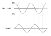
図3に示すように、振幅換算回路45は、出力信号S1の信号レベルに基づいて、増幅電圧Vnが基準電圧V0(=0V)と同電圧に達した時間T0を検出し、その時間T0において可動子12が往復運動の折り返し点に達したと判断する。詳述すると、図4に示すように、巻線11aには、可動子12の往復運動に応じて正弦波状の誘起電圧Eが生じる。この誘起電圧Eの波形は、リニアアクチュエータ10の機械的な共振周波数と同一周波数である。また、この誘起電圧Eは、可動子12の振幅、変位、振動の速度、振動の加速度や振動の方向等に応じて変化する。可動子12の速度が大きくなるにしたがって当該誘起電圧Eも大きくなる。例えば、可動子12が往復運動において折り返し点である第1の位置または第2の位置(右端または左端)に達した時、すなわち可動子12の速度が零になった時、その可動子12が有する永久磁石12aの動きが一旦止まって磁束の変化がなくなるために誘起電圧Eが零となる。したがって、巻線11aの誘起電圧E(増幅電圧Vn)が零電圧となった場合に、可動子12の振動方向が切り替わったと判断でき、つまり可動子12が往復運動の折り返し点に達したと判断できる。
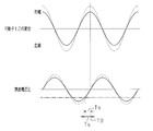
図3に示すように、振幅換算回路45は、出力信号S2の信号レベルに基づいて、増幅電圧Vnが基準電圧V1と同じ電圧に達した時間T1を検出する。さらに、振幅換算回路45は、時間T1から時間T0までの時間差Tsを検出し、その時間差Tsに基づき可動子12の速度(振幅)を求める。具体的には、振幅換算回路45は、誘起電圧Eが所定の電圧(基準電圧V1)になった時から振幅の折り返しタイミング(時間T0)までの時間(時間差Ts)を測定し、その時間差Tsを速度(振幅)に換算している。詳述すると、リニアアクチュエータ10は一定周波数で振動し、その可動子12の位置及び速度は正弦曲線に則って変化する。したがって、上述した時間差Tsを測定することにより、リニアアクチュエータ10の駆動状態(正弦曲線)を特定することができ、可動子12の速度(振幅)を特定することができる。
別の見方をすれば、巻線11aの誘起電圧Eは、電磁力と振幅と周波数とにより決定される。この場合、誘起電圧Eの変動は可動子12の振幅のみに依存するため、可動子12の振幅が大きくなるほど当該誘起電圧Eも大きくなる。このため、図5に示すように、可動子12の振幅が大きくなると時間差Tsは短くなり(破線参照)、逆に可動子12の振幅が小さくなると時間差Tsは長くなる(実線参照)。これにより、この時間差Tsを振幅(速度)として換算することができる。
なお、基準電圧V1を基準電圧V0よりも所定電圧だけ高い電圧に設定した場合には、増幅電圧Vnが基準電圧V0と同じ電圧に達した時間T0から増幅電圧Vnが基準電圧V1と同電圧になった時間T1までの時間差Tsを検出して振幅(速度)を求めればよい。
図3に示すように、このような振幅検出は、巻線11aに駆動電流Idが流れていない非通電期間Tncにおいて実行される。なお、この非通電期間Tncは、例えば巻線11aへの駆動電流出力をPWM制御で行うとともに、PWM出力の最大出力幅を制限することで設定されてもよい。また、可動子12の片方向への駆動がPWM制御で行われ、他方向への駆動が固定出力で行われ、その固定出力の後の残り時間が非通電期間Tncとして設定されてもよい。
図3の例では、上述の振幅検出を、片方向の折り返し点(右側の折り返し点)のみで実行するようにしているが、両方向の折り返し点(右側及び左側の折り返し点)で実行するようにしてもよい。
図2に示す振幅換算回路45は、検出した可動子12の速度(振幅)を示す信号を、メモリ46と制御出力部50とに供給する。
制御回路47は、メモリ46に格納された時間的に異なる2つの速度(例えば最新の検出値である速度とその直前の検出値である速度)を比較して、その比較結果を示す差に応じて、そのときの状況を判定して可動子12の制御方法を変更する。
詳しくは、制御回路47は、比較結果を示す差が予め設定されたパワーアップ判定条件を満たすと判定した場合、可動子12の速度が大きくなるように制御方法を通常制御からパワーアップ制御に変更する。
本実施形態のパワーアップ判定条件は、予め設定された可動子12の周期数である16周期の範囲内で、比較結果が予め設定されたパワーアップ要素条件を満たす回数が、予め設定された回数である2回以上に達したときに満たされる判定条件を含む。また、本実施形態のパワーアップ要素条件は、検出値の速度がその直前の検出値の速度よりも予め設定された第1設定値th1(図6参照)以上大きく、且つ前記直前の検出値の速度が前々回の検出値よりも小さいときに満たされる第1条件に設定されている。例えば、図6に示すように速度(検出値)が変動した場合、破線で示す16周期の範囲内で、第1条件が2回以上満たされると、制御方法をパワーアップ制御に変更し、第1条件が2回未満しか満たされないと、制御方法を通常制御からパワーアップ制御に変更しない。尚、図6は、周期s1と周期s2とで第1条件(パワーアップ要素条件)が満たされている例を図示し、この場合、制御方法を通常制御からパワーアップ制御に変更する。また、本実施形態の可動子12の1周期は、約4m秒である。
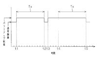
また、本実施形態の制御回路47は、パワーアップ制御に変更してから予め設定された復帰設定時間Tx(例えば、数秒間であって、図7参照)が経過するまでの間も前記比較結果に応じてパワーアップ制御を維持するか否かを判定する。制御回路47は、復帰設定時間Tx中にパワーアップ制御を維持すると判定した場合に復帰設定時間Txのカウント値をリセットし、復帰設定時間Tx中にパワーアップ制御を維持しないと判定した場合に制御方法を元の制御方法(通常制御)に戻す。尚、図7の時間の目盛り1つは、可動子12の16周期に対応している。
制御出力部50は、振幅換算回路45にて検出された可動子12の折り返しタイミングに合わせて駆動電流Idの出力タイミングを制御するようにPWM信号を生成する。具体的には、図3に示すように、制御出力部50は、可動子12が折り返し点に達してから所定時間Ta後に2つのスイッチング素子Q1,Q4を所定時間Tbの間オンさせて、可動子12を第1方向に向かって移動させるための駆動電流Idを巻線11aに供給させる。また、制御出力部50は、可動子12が折り返し点に達してから所定時間Tc(>Ta+Tb)後に2つのスイッチング素子Q2,Q3を所定時間Tdの間オンさせて、可動子12を第1方向とは反対方向に向かって移動させるための駆動電流Idを巻線11aに供給させる。
さらに、制御出力部50は、振幅換算回路45からの制御情報に基づいて、可動子12の振幅(速度)が目標値と一致するようにPWM信号を生成する。例えば、制御出力部50は、可動子12の振幅(速度)が目標値に一致するように駆動電流Idの電流量を制御する。具体的には、制御出力部50は、可動子12の振幅(速度)が目標値に一致するように、上述した2つの所定時間Tb,Td(通電時間)の長さ、つまりデューティ比を制御して駆動電流Idの電流量を制御する。本実施形態では、制御方法を通常制御からパワーアップ制御に変更する際に、可動子12の振幅(速度)の目標値が、通常制御時よりも大きくなるように設定される。
次に、このように構成された電気かみそり1(特に、制御回路47)の動作及び作用を図6及び図7に従って説明する。
例えば、今、駆動回路30から供給される駆動電流Idによってリニアアクチュエータ10の可動子12が往復運動され、可動子12と共に図示しない内刃が往復運動されている。この場合、可動子12が折り返し点に達するごとに可動子12の速度(振幅)が検出される。可動子12の速度(振幅)は、メモリ46に格納される。制御回路47は、メモリ46に格納された時間的に異なる2つの速度を比較する。制御回路47は、その比較結果を示す差に応じて、そのときの状況を判定して、可動子12の制御方法を変更する。
例えば、図6に破線で示す16周期の範囲内では、2つの周期s1,s2で、可動子12の速度がその直前の速度よりも予め設定された第1設定値th1以上大きく、且つ直前の速度が前々回の速度よりも小さいという第1条件が満たされている。尚、直前の速度とは、周期s1,s2の1目盛り前の速度であって、前々回の速度とは、周期s1,s2の2目盛り前の速度である。この場合(図6参照)では、周期s1,s2の直前(1目盛り前)のタイミングで負荷の急激な増大が生じていることから髭(比較的剛毛)を除毛した可能性が高いと判定される。16周期の範囲内で複数回、髭(比較的剛毛)を除毛した可能性が高いと判定されることから、髭の濃い部分を除毛していると判定され、制御方法が通常制御からパワーアップ制御に変更される。尚、16周期の範囲内で複数回、髭を除毛した可能性が高くないと判定された場合では、髭の薄い部分や剃り残したイレギュラーな髭を除毛していると判定され、制御方法は通常制御からパワーアップ制御に変更されず、通常制御を維持する。
そして、例えば、図7に示すように、タイミングt1で制御方法が通常制御からパワーアップ制御に変更されると、予め設定された復帰設定時間Txが経過するまでの間も本実施形態では上記と同様の比較(パワーアップ判定条件)にてパワーアップ制御を維持するか否かが判定される。そして、復帰設定時間Txにおいてパワーアップ制御を維持しないと判定する(パワーアップ判定条件が満たされない)と、制御方法が元の制御方法(通常制御)に戻される(タイミングt2)。また、タイミングt3で制御方法が通常制御からパワーアップ制御に変更され、それから復帰設定時間Tx内のタイミングt4でパワーアップ制御を維持すると判定される(パワーアップ判定条件が満たされる)と、復帰設定時間Txに関連するカウント値がリセットされる。そして、そこから復帰設定時間Txにおいてパワーアップ制御を維持しないと判定されると、制御方法が元の制御方法(通常制御)に戻される(タイミングt5)。
次に、上記実施の形態の特徴的な効果を以下に記載する。
(1)検出値である速度と過去に検出した検出値である速度とが比較され、その比較結果を示す差に応じてより状況が高確率で判定されて可動子12の制御方法が変更されるので、より状況に応じた最適な制御を行うことができる。具体的には、髭を除毛したことを高確率で判定することができ、それによって最適な制御を行うことができる。
(2)パワーアップ判定条件を満たすと、可動子12の速度が大きくなるように制御方法が通常制御からパワーアップ制御に変更されるため、例えば髭の濃い部分も良好に除毛作業を行うことができる。また、パワーアップ判定条件を満たさない場合は、通常(非パワーアップ)制御によって、肌への刺激を抑えることができるとともに無駄な電力消費を抑えることができる。
(3)パワーアップ判定条件は、予め設定された可動子12の周期数(16周期)の範囲内で、比較結果が予め設定されたパワーアップ要素条件(第1条件)を満たす回数が、予め設定された設定回数(2回)以上となったときに満たされる判定条件を含む。よって、より最適な制御を行うことが可能となる。即ち、パワーアップ判定条件がこのような判定条件を含まない場合では、単発的な髭の除毛によってもパワーアップ制御され易くなるといった制御になるが、これを抑え、髭の濃い部分を高精度に判定してより最適な制御を行うことが可能となる。
(4)パワーアップ要素条件は、検出値の速度がその直前の検出値の速度よりも予め設定された第1設定値th1以上大きく、且つ直前の検出値の速度が前々回の検出値よりも小さいときに満たされる第1条件を含む。即ち、パワーアップ要素条件は、まず速度が小さくなり、次にその速度が第1設定値th1以上大きくなったときに満たされる第1条件を含む。このようにすると、直前の検出値を検出した際(周期s1,s2の直前(1目盛り前)のタイミング)に、高確率で除毛したことが予想されるため、より最適な制御を行うことができる。
(5)制御方法を通常制御からパワーアップ制御に変更してから予め設定された復帰設定時間Txが経過するまでの間も比較結果に応じてパワーアップ制御を維持するか否かを判定した。復帰設定時間Txにおいてパワーアップ制御を維持すると判定した場合に復帰設定時間Txのカウント値をリセットし、復帰設定時間Txにおいてパワーアップ制御を維持しないと判定した場合に、制御方法が元の制御方法(通常制御)に戻される。よって、より状況に応じた最適な制御を行うことができる。具体的には、髭の濃い部分を除毛している状態が続いているにも関わらず通常制御に戻ることがないようにすることができ、復帰設定時間Txの経過後は、通常制御によって、肌への刺激を抑えることができるとともに無駄な電力消費を抑えることができる。
上記実施形態は、以下のように変更してもよい。
・上記実施形態のパワーアップ判定条件は、検出値(可動子12の変位(振幅)、速度及び加速度のうちの少なくとも一つ)と過去に検出した検出値とを比較、即ち時間的に異なる2つの検出値を比較しその比較結果を示す差に応じて判定する他の条件に変更してもよい。
また、前記パワーアップ要素条件を同様に他の条件に変更してもよい。
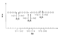
例えば、パワーアップ判定条件が、検出値とその直前の検出値との差があるときに満たされるように設定されてもよい(有差条件)。このようにすると、例えば、図8に示すように速度(検出値)が変動した場合、各周期(タイミング)s11~s16でパワーアップ判定条件(有差条件)が満たされて、通常制御にある場合、制御方法はパワーアップ制御に変更される。
また、例えば、パワーアップ判定条件は、検出値(速度)とその直前の検出値(速度)との差が予め設定された第2設定値th2以上であるときに満たされる第2条件を含んでもよい。このようにすると、例えば、図8に示すように速度(検出値)が変動した場合、各周期(タイミング)s11~s14でパワーアップ判定条件(第2条件)が満たされて、通常制御にある場合、パワーアップ制御に変更される。尚、図8に示すように速度(検出値)が変動した場合、各周期(タイミング)s15,s16ではパワーアップ判定条件(第2条件)が満たされない。従って、制御方法が、そのとき通常制御であってもパワーアップ制御に変更されず通常制御に維持される。また、この第2条件は、パワーアップ要素条件としてもよい。
また、例えば、パワーアップ判定条件は、上記実施形態の第1条件を含んでもよい。このようにすると、例えば、図9に示すように速度(検出値)が変動した場合、各周期(タイミング)s21,s22でパワーアップ判定条件(第1条件)が満たされて通常制御に設定されている場合、制御方法がパワーアップ制御に変更される。即ち、この例では、上記実施形態の判定条件がなく、周期(タイミング)s21の時点でパワーアップ制御に変更される。
・上記実施形態では、パワーアップ判定条件は、一定であるものとしたが、これに限定されない。制御回路47は、可動子12が駆動されてから経過した時間に応じて可動子12の制御方法を変更する条件(パワーアップ判定条件)を変更してもよい。
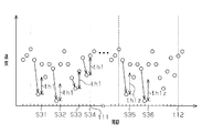
例えば、可動子12が駆動されてから予め設定された時間が経過すると、上記実施形態における第1設定値th1をより大きな値の第1設定値th1z(図10参照)に変更してもよい。また、上記実施形態の複数判定条件の数値は変更してもよく、例えば、パワーアップ判定条件は、16周期の範囲内で、パワーアップ要素条件を満たす回数が3回以上となったときに満たされる判定条件を含んでもよい。
このようにした場合であって図10に示すように速度(検出値)が変動した場合の作用を説明する。まず可動子12が駆動されてからの経過時間が予め設定された時間よりも短い時間帯(図10において、左側)では、各周期(タイミング)s31~s34でパワーアップ要素条件(第1条件)が満たされる。これにより、タイミングt11で複数判定条件、ひいてはパワーアップ判定条件が満たされて、制御方法が通常制御からパワーアップ制御に変更される。また、可動子12が駆動されてからの経過時間が予め設定された時間よりも長い時間帯(図10において、右側)では、各周期(タイミング)s35,s36でパワーアップ要素条件(第1条件)が満たされる。しかし、タイミングt12では複数判定条件、ひいてはパワーアップ判定条件が満たされず、制御方法が通常制御からパワーアップ制御に変更されずに通常制御に維持される。尚、図10では、説明の便宜上、時間帯毎の速度(検出値)の変動を同じとしている。しかし、早い時間帯では、制御方法は、通常制御からパワーアップ制御に変更され、遅い時間帯では(大きな値の第1設定値th1zとされることで)制御方法は、通常制御からパワーアップ制御に変更されずに通常制御に維持される。即ち、駆動されてから早い時間帯では、まだ多くの髭が残っている可能性が高く、簡単な条件で制御方法が通常制御からパワーアップ制御に変更される。これにより、良好に除毛作業を行うことができる。また、駆動されてから遅い時間帯では、多くの髭が残っている可能性が低く、簡単な条件で制御方法が通常制御からパワーアップ制御に変更されない。これにより、肌への刺激を抑えることができるとともに無駄な電力消費を抑えることができる。つまり、より状況に応じた最適な制御を行うことができる。
・上記実施形態では、制御方法を通常制御からパワーアップ制御に変更してから復帰設定時間Txが経過するまでの間もパワーアップ制御を維持するか否かを判定したが、その判定を行わずに復帰設定時間Txが経過すると、元の制御方法(通常制御)に戻してもよい。
このようにすると、例えば、図11に示すように、タイミングt21で制御方法が通常制御からパワーアップ制御に変更されると、その後の検出値(速度)の変化に係わらず、予め設定された復帰設定時間Txが経過すると、元の制御方法(通常制御)に戻される(タイミングt22)。また、タイミングt23で制御方法が通常制御からパワーアップ制御に変更されると、その後の検出値(速度)の変化に係わらず、予め設定された復帰設定時間Txが経過すると、元の制御方法(通常制御)に戻される(タイミングt24)。このようにしても、例えば、無駄な電力消費を抑えることができる。また、上記実施形態のパワーアップ制御を維持するか否かの判定は、パワーアップ制御に変更する際のパワーアップ判定条件とは異なる条件で行うように変更してもよい。
・上記実施形態では、制御回路47は、パワーアップ判定条件が満たされると制御方法を通常制御からパワーアップ制御に変更したが、逆にパワーダウン判定条件が満たされると可動子12の速度が小さくなるように制御方法をパワーダウン制御に変更してもよい。また、制御回路は、比較結果である検出値の差(即ち、それから判定される状況)に応じて制御方法を3段階以上に変更するようにしてもよい。
・上記実施形態では、検出値である速度を基準電圧と比較したが、可動子12の変位(振幅)、速度及び加速度のうちの少なくとも一つを基準電圧と比較して、その比較結果を示す差に応じて(状況を判定して)可動子の制御方法を変更するようにしてもよい。
・上記実施形態では、可動子12の振幅の目標値を変更することで可動子12の制御方法を変更するようにしたが、これに限らず、例えば巻線11aに供給する駆動電流Idの周波数の目標値を変更することで可動子12の制御方法を変更するようにしてもよい。また、振幅の目標値と駆動電流Idの周波数の目標値との双方を変更することで可動子12の制御方法を変更するようにしてもよい。
・上記実施形態では、巻線11aに発生する誘起電圧Eを検出することにより可動子12の速度(振幅)を検出するようにしたが、その速度と相関のある可動子12の変位や加速度を検出するようにしてもよい。また、検出手段として加速度センサ等を別途設け、そのセンサ出力などから可動子12の変位、速度及び加速度の少なくとも一つを検出するようにしてもよい。
・上記実施形態における可動子12は、永久磁石12aの代わりに電磁石を備えるようにしてもよい。この場合には、電磁石からなる固定子11の代わりに永久磁石からなる固定子を用いるようにしてもよい。
・上記実施形態では、除毛器具としての電気かみそり1に具体化したが、髭以外の除毛を行うバリカンや脱毛器等の他の除毛器具に具体化して実施してもよい。
Claims (9)
- 電磁石および永久磁石のうちの一方を含む固定子と、永久磁石および電磁石のうちの他方を含む可動子とを含むリニアアクチュエータを備えた除毛器具であって、
前記可動子の変位、速度及び加速度のうちの少なくとも一つを検出する検出ユニットと、
前記検出ユニットの検出値と過去に検出された検出値とを比較して、比較結果を示す差に応じて前記可動子の制御方法を変更する制御部とを備えた、除毛器具。 - 請求項1に記載の除毛器具において、
前記制御部は、前記比較結果が予め設定されたパワーアップ判定条件を満たすと判定した場合、前記可動子の制御方法を通常制御から前記可動子の速度を増大させるためのパワーアップ制御に変更する、除毛器具。 - 請求項2に記載の除毛器具において、
前記パワーアップ判定条件は、予め設定された時間の範囲、又は予め設定された可動子の周期数の範囲内で、前記比較結果が予め設定されたパワーアップ要素条件を満たす回数が、予め設定された回数以上に達したときに満たされる判定条件を含む、除毛器具。 - 請求項2又は3に記載の除毛器具において、
前記パワーアップ判定条件又はパワーアップ要素条件は、前記検出値がその直前の検出値よりも予め設定された第1設定値以上大きく、且つ前記直前の検出値が前々回の検出値よりも小さいときに満たされる第1条件を含む、除毛器具。 - 請求項2又は3に記載の除毛器具において、
前記パワーアップ判定条件又はパワーアップ要素条件は、前記検出値とその直前の検出値との差が予め設定された第2設定値以上であるときに満たされる第2条件を含む、除毛器具。 - 請求項1乃至5のいずれか1項に記載の除毛器具において、
前記制御部は、前記可動子が駆動されてからの経過時間に応じて前記可動子の制御方法を変更する条件を変更する、除毛器具。 - 請求項1乃至6のいずれか1項に記載の除毛器具において、
前記制御部は、
前記可動子の制御方法を変更してから予め設定された復帰設定時間が経過するまでの時間をカウントし、前記復帰設定時間において比較結果に応じて変更した制御方法を維持するかどうかを判定し、
前記復帰設定時間内に前記制御方法を維持すると判定した場合に前記復帰設定時間に関連するカウント値をリセットし、
前記復帰設定時間内に前記制御方法を維持しないと判定した場合に制御方法を元の制御方法に戻す、除毛器具。 - 請求項1乃至6のいずれか1項に記載の除毛器具において、
前記制御部は、前記可動子の制御方法を変更してから予め設定された復帰設定時間が経過すると、制御方法を元の制御方法に戻す、除毛器具。 - 電磁石および永久磁石のうちの一方を含む固定子と、永久磁石および電磁石のうちの他方を含む可動子とを含むリニアアクチュエータを備えた除毛器具の駆動方法であって、
前記可動子の変位、速度及び加速度のうちの少なくとも一つを検出すること、
該検出値と過去に検出した検出値とを比較して、比較結果を示す差に応じて前記可動子の制御方法を変更する、除毛器具の駆動方法。
Priority Applications (3)
| Application Number | Priority Date | Filing Date | Title |
|---|---|---|---|
| US14/409,423 US9537441B2 (en) | 2012-07-18 | 2013-05-20 | Epilator and method for driving epilator |
| EP13819204.2A EP2875918B1 (en) | 2012-07-18 | 2013-05-20 | Epilator and method for driving epilator |
| CN201380032922.4A CN104379309B (zh) | 2012-07-18 | 2013-05-20 | 脱毛器和用于驱动脱毛器的方法 |
Applications Claiming Priority (2)
| Application Number | Priority Date | Filing Date | Title |
|---|---|---|---|
| JP2012-159620 | 2012-07-18 | ||
| JP2012159620A JP5984053B2 (ja) | 2012-07-18 | 2012-07-18 | 除毛器具、及び除毛器具の駆動方法 |
Publications (1)
| Publication Number | Publication Date |
|---|---|
| WO2014013659A1 true WO2014013659A1 (ja) | 2014-01-23 |
Family
ID=49948503
Family Applications (1)
| Application Number | Title | Priority Date | Filing Date |
|---|---|---|---|
| PCT/JP2013/003205 Ceased WO2014013659A1 (ja) | 2012-07-18 | 2013-05-20 | 除毛器具、及び除毛器具の駆動方法 |
Country Status (5)
| Country | Link |
|---|---|
| US (1) | US9537441B2 (ja) |
| EP (1) | EP2875918B1 (ja) |
| JP (1) | JP5984053B2 (ja) |
| CN (1) | CN104379309B (ja) |
| WO (1) | WO2014013659A1 (ja) |
Cited By (1)
| Publication number | Priority date | Publication date | Assignee | Title |
|---|---|---|---|---|
| CN108599665A (zh) * | 2018-05-15 | 2018-09-28 | 华中科技大学 | 一种含法向力的直线感应电机最小损耗控制方法及系统 |
Families Citing this family (7)
| Publication number | Priority date | Publication date | Assignee | Title |
|---|---|---|---|---|
| EP3327910A1 (en) * | 2016-11-23 | 2018-05-30 | Braun GmbH | Vibration motor for an electric hand-held appliance |
| WO2018096421A1 (en) * | 2016-11-23 | 2018-05-31 | Braun Gmbh | Shaver motor speed control |
| EP3427910B1 (en) * | 2017-07-14 | 2020-08-19 | Braun GmbH | Method for determining the time behavior of a cyclic motor process during use of an electrical hair removal device and hair removal device |
| WO2021003213A1 (en) | 2019-07-01 | 2021-01-07 | Spectrum Brands, Inc. | Electric grooming appliance including magnetic coupling system |
| WO2021252731A1 (en) | 2020-06-11 | 2021-12-16 | Andis Company | Hair clipper with linear actuator |
| EP4124424B1 (en) | 2021-07-29 | 2024-01-31 | Braun GmbH | Hair removal device |
| CN120979279A (zh) * | 2025-05-28 | 2025-11-18 | 深圳术叶创新科技有限公司 | 直线电机的驱动控制方法及相关装置 |
Citations (9)
| Publication number | Priority date | Publication date | Assignee | Title |
|---|---|---|---|---|
| JPH0686873A (ja) * | 1992-09-09 | 1994-03-29 | Sanyo Electric Co Ltd | 電気かみそり |
| JPH07265559A (ja) * | 1994-03-28 | 1995-10-17 | Matsushita Electric Works Ltd | 往復式電気かみそり |
| JPH0965634A (ja) * | 1995-08-28 | 1997-03-07 | Matsushita Electric Works Ltd | リニア振動モータの制御装置 |
| JPH10243622A (ja) * | 1997-02-25 | 1998-09-11 | Matsushita Electric Works Ltd | リニア振動モータの駆動制御方法 |
| JP2001016892A (ja) * | 1999-06-25 | 2001-01-19 | Matsushita Electric Works Ltd | リニア振動モータの駆動制御方法 |
| JP2004336988A (ja) * | 2003-04-14 | 2004-11-25 | Matsushita Electric Ind Co Ltd | モータ駆動装置 |
| JP2005532018A (ja) * | 2002-06-29 | 2005-10-20 | ブラウン ゲーエムベーハー | 小型電気機器の振動型電気モータ制御方法 |
| JP2006034082A (ja) * | 2004-06-14 | 2006-02-02 | Matsushita Electric Works Ltd | 駆動装置、および駆動方法 |
| JP2009240047A (ja) * | 2008-03-26 | 2009-10-15 | Panasonic Electric Works Co Ltd | 電磁アクチュエータの駆動方法 |
Family Cites Families (14)
| Publication number | Priority date | Publication date | Assignee | Title |
|---|---|---|---|---|
| US5274735A (en) * | 1991-12-16 | 1993-12-28 | Sanyo Electric Co., Ltd. | Electric shaver |
| US5367599A (en) | 1992-05-27 | 1994-11-22 | Sanyo Electrical Co., Ltd. | Electric shaver in which motor rotational speed is controlled according to beard thickness |
| DE4320958A1 (de) * | 1993-06-24 | 1995-01-12 | Braun Ag | Gerät zum Entfernen von Körperhaaren |
| WO1995026261A1 (en) * | 1994-03-28 | 1995-10-05 | Matsushita Electric Works, Ltd. | Reciprocatory dry shaver |
| US5692529A (en) | 1995-04-18 | 1997-12-02 | Fekete; Janet | Shaving razor with integral mirror |
| EP0748038B1 (en) * | 1995-06-05 | 2002-08-21 | Kollmorgen Corporation | System and method for controlling brushless permanent magnet motors |
| FR2747606B1 (fr) | 1996-04-17 | 1998-08-28 | Feldman Marcel Marc | Rasoir de surete |
| CN2403552Y (zh) | 2000-01-19 | 2000-11-01 | 天津大学 | 便携式筒形刀柄非电动剃须刀 |
| JP4786056B2 (ja) * | 2001-04-18 | 2011-10-05 | 九州日立マクセル株式会社 | 電気かみそり |
| US7151348B1 (en) | 2003-04-14 | 2006-12-19 | Matsushita Electric Industrila Co., Ltd. | Motor driving apparatus |
| JP4301913B2 (ja) * | 2003-09-29 | 2009-07-22 | オークマ株式会社 | モータ制御装置 |
| EP1610447B1 (en) | 2004-06-14 | 2009-09-09 | Matsushita Electric Works, Ltd. | Driving unit |
| TWI404324B (zh) * | 2008-05-15 | 2013-08-01 | Delta Electronics Inc | 馬達控制裝置及其控制方法 |
| JP5895154B2 (ja) | 2011-01-21 | 2016-03-30 | パナソニックIpマネジメント株式会社 | リニアアクチュエータの駆動方法 |
-
2012
- 2012-07-18 JP JP2012159620A patent/JP5984053B2/ja active Active
-
2013
- 2013-05-20 CN CN201380032922.4A patent/CN104379309B/zh active Active
- 2013-05-20 US US14/409,423 patent/US9537441B2/en active Active
- 2013-05-20 EP EP13819204.2A patent/EP2875918B1/en active Active
- 2013-05-20 WO PCT/JP2013/003205 patent/WO2014013659A1/ja not_active Ceased
Patent Citations (9)
| Publication number | Priority date | Publication date | Assignee | Title |
|---|---|---|---|---|
| JPH0686873A (ja) * | 1992-09-09 | 1994-03-29 | Sanyo Electric Co Ltd | 電気かみそり |
| JPH07265559A (ja) * | 1994-03-28 | 1995-10-17 | Matsushita Electric Works Ltd | 往復式電気かみそり |
| JPH0965634A (ja) * | 1995-08-28 | 1997-03-07 | Matsushita Electric Works Ltd | リニア振動モータの制御装置 |
| JPH10243622A (ja) * | 1997-02-25 | 1998-09-11 | Matsushita Electric Works Ltd | リニア振動モータの駆動制御方法 |
| JP2001016892A (ja) * | 1999-06-25 | 2001-01-19 | Matsushita Electric Works Ltd | リニア振動モータの駆動制御方法 |
| JP2005532018A (ja) * | 2002-06-29 | 2005-10-20 | ブラウン ゲーエムベーハー | 小型電気機器の振動型電気モータ制御方法 |
| JP2004336988A (ja) * | 2003-04-14 | 2004-11-25 | Matsushita Electric Ind Co Ltd | モータ駆動装置 |
| JP2006034082A (ja) * | 2004-06-14 | 2006-02-02 | Matsushita Electric Works Ltd | 駆動装置、および駆動方法 |
| JP2009240047A (ja) * | 2008-03-26 | 2009-10-15 | Panasonic Electric Works Co Ltd | 電磁アクチュエータの駆動方法 |
Cited By (1)
| Publication number | Priority date | Publication date | Assignee | Title |
|---|---|---|---|---|
| CN108599665A (zh) * | 2018-05-15 | 2018-09-28 | 华中科技大学 | 一种含法向力的直线感应电机最小损耗控制方法及系统 |
Also Published As
| Publication number | Publication date |
|---|---|
| CN104379309B (zh) | 2016-04-20 |
| EP2875918A4 (en) | 2015-12-09 |
| CN104379309A (zh) | 2015-02-25 |
| US20150288312A1 (en) | 2015-10-08 |
| JP2014023274A (ja) | 2014-02-03 |
| EP2875918B1 (en) | 2020-11-04 |
| US9537441B2 (en) | 2017-01-03 |
| JP5984053B2 (ja) | 2016-09-06 |
| EP2875918A1 (en) | 2015-05-27 |
Similar Documents
| Publication | Publication Date | Title |
|---|---|---|
| JP5984053B2 (ja) | 除毛器具、及び除毛器具の駆動方法 | |
| JP5895154B2 (ja) | リニアアクチュエータの駆動方法 | |
| EP2106019B1 (en) | Method for controlling operation of a linear vibration motor | |
| US8143817B2 (en) | Electromagnetic actuator driving method | |
| JP3932741B2 (ja) | 振動型リニアアクチュエータ | |
| JP5290320B2 (ja) | 振動モータを有する構成体及び振動モータを制御する方法 | |
| JPH10243622A (ja) | リニア振動モータの駆動制御方法 | |
| JP5688559B2 (ja) | 電気かみそりおよびその制御装置 | |
| US10016041B2 (en) | Hair removal tool | |
| JP4600117B2 (ja) | 駆動装置、および駆動方法 | |
| ATE438947T1 (de) | Vorrichtung zur regelung des ankerhubs in einem reversierenden linearantrieb | |
| JPH10243688A (ja) | リニア振動モータの起動制御方法 | |
| JP3945254B2 (ja) | 電動歯ブラシ | |
| JP6040043B2 (ja) | リニアアクチュエーター | |
| HK1132385A (en) | Electromagnetic actuator driving method | |
| JP2015211508A (ja) | 振動型アクチュエーター、その制御装置、振動型アクチュエーターを備える電動装置、および、振動型アクチュエーターのプログラム | |
| HK1136392A (en) | Method for controlling operation of a linear vibration motor |
Legal Events
| Date | Code | Title | Description |
|---|---|---|---|
| WWE | Wipo information: entry into national phase |
Ref document number: 201380032922.4 Country of ref document: CN |
|
| 121 | Ep: the epo has been informed by wipo that ep was designated in this application |
Ref document number: 13819204 Country of ref document: EP Kind code of ref document: A1 |
|
| WWE | Wipo information: entry into national phase |
Ref document number: 2013819204 Country of ref document: EP |
|
| WWE | Wipo information: entry into national phase |
Ref document number: 14409423 Country of ref document: US |
|
| NENP | Non-entry into the national phase |
Ref country code: DE |