WO2014013687A1 - Dispositif de traitement de vêtement - Google Patents
Dispositif de traitement de vêtement Download PDFInfo
- Publication number
- WO2014013687A1 WO2014013687A1 PCT/JP2013/004129 JP2013004129W WO2014013687A1 WO 2014013687 A1 WO2014013687 A1 WO 2014013687A1 JP 2013004129 W JP2013004129 W JP 2013004129W WO 2014013687 A1 WO2014013687 A1 WO 2014013687A1
- Authority
- WO
- WIPO (PCT)
- Prior art keywords
- door
- latch
- force
- clothing processing
- processing apparatus
- Prior art date
- Legal status (The legal status is an assumption and is not a legal conclusion. Google has not performed a legal analysis and makes no representation as to the accuracy of the status listed.)
- Ceased
Links
Images





Classifications
-
- D—TEXTILES; PAPER
- D06—TREATMENT OF TEXTILES OR THE LIKE; LAUNDERING; FLEXIBLE MATERIALS NOT OTHERWISE PROVIDED FOR
- D06F—LAUNDERING, DRYING, IRONING, PRESSING OR FOLDING TEXTILE ARTICLES
- D06F37/00—Details specific to washing machines covered by groups D06F21/00 - D06F25/00
- D06F37/42—Safety arrangements, e.g. for stopping rotation of the receptacle upon opening of the casing door
Definitions
- the present invention relates to a clothing processing apparatus having a storage tank for storing clothing by performing at least one of washing, dehydration and drying on the clothing.
- a door opening and closing structure for opening and closing a door for putting in and out laundry is disclosed (for example, see Patent Document 1).
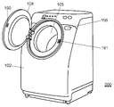
- FIG. 11 is a perspective view showing an external appearance of a conventional drum type washing machine 200
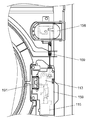
- FIG. 12 is a plan view showing a door opening / closing structure of the drum type washing machine 200.
- a door 108 is provided on the front side of the housing 102.
- a door opening button 156 is provided at a position adjacent to the door 108.
- the locking plate 113 of the opening / closing lock portion 159 is rotated via the engagement spring 169, and the locking of the latch 190 of the door 108 fitted in the latch receiver 191 is released. Is opened. If it is detected that the door 108 is open by detecting this unlocking, the rotation of the washing and dewatering tub 105 is stopped.
- the door can be opened with a predetermined force or less, and by the reaction force of the clothing in the storage tub during processing such as normal washing Provides a clothing processing apparatus that does not easily open the door.
- a clothing processing apparatus comprising: a housing; a housing tank disposed in the housing for housing the clothing; an opening formed on the front side of the housing for putting clothes in and out of the housing tank;
- a door that can be freely opened and closed and a door lock device that locks the door are provided.
- the door has a latch having a claw portion
- the door lock device has a locking portion
- the claw portion of the latch is configured to be locked by the locking portion, and the claw portion is locked.
- the slidable contact portion that comes into sliding contact with the locking portion is the direction of the external force that acts on the locking portion first when trying to open the door while the claw portion is locked to the locking portion. Is formed of a plurality of continuous surfaces having obtuse angles and different obtuse angles.
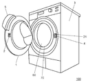
- FIG. 1 is a perspective view showing a state in which a door of a clothing processing apparatus according to a first embodiment of the present invention is opened.
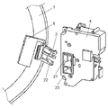
- FIG. 2 is a perspective view showing a door latch and a door lock device of the clothing processing apparatus according to the first embodiment of the present invention.
- FIG. 3A is a cross-sectional view of the main part showing the progress of the latch of the clothing processing apparatus according to the first embodiment of the present invention being inserted into the door lock device.
- FIG. 3B is a cross-sectional view of the main part showing the progress of the push plate portion of the clothing processing apparatus according to the first embodiment of the present invention being inserted into the door lock device.
- FIG. 1 is a perspective view showing a state in which a door of a clothing processing apparatus according to a first embodiment of the present invention is opened.
- FIG. 2 is a perspective view showing a door latch and a door lock device of the clothing processing apparatus according to the first embodiment of the present invention.
- FIG. 3A is a cross-section
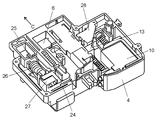
- FIG. 4 is a perspective view showing an internal configuration of the door lock device of the clothing processing apparatus according to the first embodiment of the present invention.
- FIG. 5 is a plan view showing an internal configuration in a state where a sliding member of the door lock device of the clothing processing apparatus according to the first embodiment of the present invention is removed.
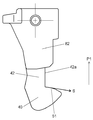
- FIG. 6 is a plan view showing the shape of the latch of the clothing processing apparatus according to the first embodiment of the present invention.
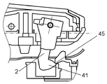
- FIG. 7A is a diagram showing a relationship between the latch and the door lock device when the door is pushed from the inside of the storage tank of the clothing processing apparatus according to the first embodiment of the present invention.
- FIG. 7B is a diagram illustrating a relationship between the latch and the door lock device when the door is pressed from the inside of the storage tub of the clothing processing apparatus according to the first embodiment of the present invention.
- FIG. 7C is a diagram showing a relationship between the latch and the door lock device when the door is pushed from the inside of the storage tub of the clothing processing apparatus according to the first embodiment of the present invention.
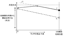
- FIG. 8 is a diagram showing a relationship between an external force that pushes the door from the inside of the storage tub of the clothing processing apparatus according to the first embodiment of the present invention and a latching allowance (locking dimension) of the latch.
- FIG. 9 is a front view showing the shape of the latch of the clothing processing apparatus according to the second embodiment of the present invention.
- FIG. 10 shows the latching force (locking dimension) between the external force that pushes the door from the inside of the storage tub and the claw portion and the locking portion of the latch in the latch of the clothing processing apparatus according to the second embodiment of the present invention. It is a figure which shows the relationship.
- FIG. 11 is a perspective view showing the appearance of a conventional drum-type washing machine.
- FIG. 12 is a plan view showing a door opening / closing structure of a conventional drum type washing machine.
- FIG. 1 is a perspective view showing a state in which the door 1 of the clothing processing apparatus 100 according to the first embodiment of the present invention is opened, and FIG. 2 shows the latch 2 and the door lock of the door 1 of the clothing processing apparatus 100.
- 3A is a perspective view showing the apparatus 4
- FIG. 3A is a cross-sectional view of a main part showing a process of inserting the latch 2 of the clothing processing apparatus 100 into the door lock device 4
- FIG. FIG. 6 is a cross-sectional view of a main part showing a process in which the push plate portion 22 is inserted into the door lock device 4.
- the door 1 of the clothing processing apparatus 100 is provided with a latch 2.
- the housing 3 is provided with a door lock device 4 so as to face the latch 2.
- the door lock device 4 is configured so that the latch 2 can be received in the latch insertion hole 21 of the door lock device 4 when the door 1 is closed.
- the clothing processing apparatus 100 includes a storage tank 60.
- the clothing processing apparatus 100 includes an opening 70 for taking clothes into and out of the storage tank 60.
- the door 1 covers the opening 70 so as to be freely opened and closed.
- FIG. 1 shows an example in which the lever 5 and the latch 2 are provided apart from each other.
- the door 1 is provided with a lever 5 for rotating the latch 2, and a push plate portion 22 that is rotated integrally with the latch 2 by the lever 5.
- the door lock device 4 includes a latch insertion hole 21 into which the latch 2 is inserted and a door opening detection hole 23 into which the push plate portion 22 is inserted.
- the lever 5 is urged by a spring in a direction in which the latch 2 is locked to the door lock device 4, and the user rotates the latch 2 by pulling the lever 5 when opening the door 1.
- FIG. 2 shows an example in which the lever 5 and the latch 2 are provided close to each other.
- a sliding member 6 formed in a box shape is provided inside the latch insertion hole 21 into which the latch 2 is inserted.
- the latch 2 is inserted into the latch insertion hole 21 of the door lock device 4, and the sliding member 6 slides in the back direction (right direction in FIG. 3A).
- the claw portion 40 of the latch 2 is locked to the locking portion 45 of the door lock device 4, and the box-shaped sliding member 6 suppresses the movement of the latch 2.
- the push plate portion 22 provided integrally with the latch 2 when the push plate portion 22 provided integrally with the latch 2 is inserted into the door opening detection hole 23 of the door lock device 4, it detects opening / closing of the door 1.
- the button 25 is pushed in the back direction (right direction in FIG. 3B).
- the contact surface between the push plate portion 22 and the button 25 is a flat surface.
- FIG. 4 is a perspective view showing an internal configuration of the door lock device 4 of the clothing processing apparatus 100 according to the first embodiment of the present invention
- FIG. 5 is a diagram in which the sliding member 6 of the door lock device 4 is removed. It is a top view which shows the internal structure of a state.
- the sliding member 6 that slides by the latch 2 is urged in the direction of arrow C by the spring 24.
- the sliding member 6 also moves in the direction of arrow C.
- FIG. 5 is a view in which the sliding member 6 is removed, but a protrusion 30 is provided at the tip of the coupling mechanism component 28, and the sliding member 6 is fixed or released by the movement of the protrusion 30. You can do it.
- the latch 2 By moving the protrusion 30 downward and fixing the sliding member 6, the latch 2 can be held so as not to rotate and the door 1 can be locked.
- the holding unit 13 When the holding unit 13 is moved by the solenoid 10, the holding unit 13 rotates the rotating lever 35 via the spring 29 and presses the switch 31. As a result, the switch 31 is in the “on” state in the locked state, and is in the “off” state in the released state. Thereby, on the clothing processing apparatus 100 side, it is possible to detect whether the door 1 is in the locked state or the released state.
- the switch 27 and the switch 31 are connected to lead wires 32 and 33, respectively, and can send an open / close signal to a control device in the housing 3. In particular, when the switch 27 is turned off, it is determined that the door 1 has been opened, and the control device quickly stops the rotation of the drum.
- the latch 2 When closing the door 1, the latch 2 together with the lever 5 has an urging force, so that the front end of the latch 2 is inserted into the latch insertion hole 21 of the door lock device 4 by pushing and closing the door 1. As the sliding member 6 slides, the door 1 can be held in the closed state.
- FIG. 6 is a plan view showing the shape of the latch 2 of the clothing processing apparatus 100 according to the first embodiment of the present invention.
- FIGS. 7A to 7C show the case where the door 1 is pushed from the inside of the storage tank 60.
- FIG. It is a figure which shows the relationship between the latch 2 and the door lock apparatus 4.
- FIG. 7A shows the initial state
- FIG. 7B shows the intermediate state
- FIG. 7C shows the state immediately before the door 1 is opened.
- the operation in which the door 1 is pushed from the inside is an operation assuming an emergency such as when the child is trapped in the storage tank 60.
- the latch 2 includes a claw portion 40 formed at the tip, a support portion 42 that supports the claw portion 40, and a rotation shaft 43 that serves as an axis when rotating in conjunction with the lever 5.
- the claw portion 40 of the latch 2 is locked to the locking portion 45 of the door lock device 4, and the shape of the sliding contact portion 41 of the latch 2 that slides with the locking portion 45 is predetermined. It has a shape. Specifically, the sliding contact portion 41 is first formed when the door 1 is pushed from the inside when the door 1 is closed and the claw portion 40 is locked by the locking portion 45.
- the sliding contact portion 41 has a first plane 41a and a second plane 41b, and an angle F with respect to the horizontal direction of the first plane 41a is 12 °, that is, an external force P1. Is an obtuse angle of 102 °, and the angle G of the second plane 41b is 24 °, that is, the angle with respect to the external force P1 is an obtuse angle of 114 °.
- 7A to 7C show the relationship between the latch 2 and the locking portion 45 of the door lock device 4 from when the door 1 is closed to immediately before it is opened.
- the latch 2 starts to rotate clockwise around the rotation shaft 43 by the generated component force P3, and gradually changes to the intermediate stage state shown in FIG. 7B. In this state, a gap begins to be generated between the seal portion 1a of the door 1 and the housing 3.
- FIG. 7B shows a state in which the portion in contact with the locking portion 45 changes from the first plane 41a of the latch 2 to the second plane 41b.
- the latch 2 further rotates, the locking dimension between the claw portion 40 and the locking portion 45 decreases, and the door 1 is finally opened.
- FIG. 7C shows a state immediately before the door 1 is opened.
- FIG. 8 is a diagram illustrating a relationship between an external force that pushes the door 1 from the inside of the storage tub 60 of the clothing processing apparatus 100 according to the first embodiment of the present invention and a latching allowance (locking dimension) of the latch 2. is there.
- the characteristic line J shown in FIG. 8 indicates the inner side with respect to the door 1 when the sliding contact portion 41 is provided with a two-stage plane (the first plane 41a and the second plane 41b) as shown in FIG.
- the latch 2 rotates with respect to the force from the angle, and the transition until the locking dimension decreases and the door opens is shown.
- the characteristic line K indicates a transition in the case where the sliding contact portion 41 is configured with one plane (angle F is 19 °) in the example shown in FIG.
- a predetermined force (corresponding to a force when the child pushes the door 1) is assumed as an upper limit to the force applied from the inside of the door 1. If the door 1 must be opened below this predetermined force, that is, below the child's force, the transition of the characteristic line K in the case of a single plane is compared with the transition of the characteristic line J.
- the latch 2 rotates clockwise with a weak force from the initial state, and the locking dimension starts to decrease. As described above, when the latch 2 starts to rotate with a weak force and the door 1 opens outward, the door 1 is also opened due to the force of clothes during washing and the like, and water leakage is likely to occur during driving. Become.
- the force at which the latch 2 starts to rotate is set as close to the predetermined force as possible.
- the door 1 is required to be opened without the latch 2 being locked while the force applied to the door 1 is equal to or less than a predetermined force. .
- the force necessary for the initial operation of the latch 2 is increased by setting the angle of the first plane 41a to a small value.
- the force for opening the door 1 exceeds the above-described predetermined force (characteristic line J1 (two-dot chain line) in FIG. 8). This is because the force of the spring urging the latch 2 is increased.
- the door 1 will not be opened below a predetermined force, so the position of sliding contact is moved from the first plane 41a to the second plane 41b while the latch 2 is rotating, and the second plane 41b
- the latch 2 can be easily rotated, and the door 1 can be opened with a predetermined force or less.
- the transition of the characteristic line J two-plane shape
- the transition of the characteristic line J has a large force for the latch 2 to move initially, and before the force exceeding the predetermined force is applied, it slides.
- the latch 2 when a force is applied from the inside of the storage tank 60, the latch 2 receives a reaction force from the locking portion 45, and the locking dimension of the latch 2 decreases (clockwise direction). ) To receive the component force P3. As a result, the latch 2 rotates and the door 1 of the storage tank can be opened. Further, the sliding contact portion 41 to be locked is constituted by a plurality of planes that form an obtuse angle with the external force P1 applied first. Therefore, the first plane 41a is set so that the force until the latch 2 starts to move (rotates) is increased to a predetermined value, and the door 1 is easily opened by the reaction force of the clothes in the storage tank 60. Can be prevented. Moreover, the force required to open the door 1 from the inside is set by setting the angle larger than the first plane 41a so that the door 1 can be easily opened after the second plane 41b. Can be adjusted.
- the conditions of the plane angle of the sliding contact portion 41 are not limited to those described in the present embodiment, and various patterns can be set.
- the sliding contact portion 41 is constituted by a plurality of planes, and the force necessary to start the rotation of the latch 2 on the first plane 41a is increased to a predetermined value, and the planes after the second plane 41b are increased. What is necessary is just to comprise so that the door 1 can be opened easily.
- the sliding contact portion 41 of the latch 2 is configured by two planes.
- the present invention is not limited to this example, and may be configured by, for example, three or more planes.
- the sliding contact part 41 is not limited to the example comprised by a plane, You may comprise by the surface containing a curved surface.
- FIG. 9 is a front view showing the shape of the latch 82 of the clothing processing apparatus 100 according to the second embodiment of the present invention
- FIG. 10 shows that the door 1 is pushed from the inside of the storage tank 60 in the latch 82. It is a figure which shows the relationship between external force and the allowance (locking dimension) of the nail
- FIG. 9 is a front view showing the shape of the latch 82 of the clothing processing apparatus 100 according to the second embodiment of the present invention
- FIG. 10 shows that the door 1 is pushed from the inside of the storage tank 60 in the latch 82. It is a figure which shows the relationship between external force and the allowance (locking dimension) of the nail
- FIG. 9 is a front view showing the shape of the latch 82 of the clothing processing apparatus 100 according to the second embodiment of the present invention
- FIG. 10 shows that the door 1 is pushed from the inside of the storage
- the latch 82 according to the second embodiment of the present invention is different from the latch 2 according to the first embodiment in that the sliding contact portion 51 that contacts and locks with the locking portion 45 is configured by only a curved surface. Is different. Since other configurations are the same as those of the latch 2 described in the first embodiment, detailed description thereof is omitted.
- the sliding contact portion 51 of the latch 2 is constituted by a combination of a plurality of convex curved surfaces having different curvature radii.
- the angle of the tangent S of the slidable contact portion 51 that intersects the side surface 42a of the support portion 42 is formed so as to form an obtuse angle with the direction of the external force P1 indicated by an arrow that first acts on the locking portion 45.
- the sliding contact portion 51 of the latch 82 is configured by a plurality of convex curved surfaces having different curvature radii (for example, a shape having a curvature radius that decreases toward the tip). it can).
- the convex curved surface has an obtuse angle between the direction of the external force P1 indicated by the arrow and the tangent to the curved surface, and the obtuse angle increases toward the tip.
- This curved surface shape can be determined by the force pushed from the inside of the door 1, the reaction force received by the latch 82 in the rotational direction, and the biasing force applied to the latch 82 by the spring.
- the characteristic line L shown in FIG. 10 indicates that when the sliding contact portion 51 of the latch 82 is formed of a curved surface, the latch 82 rotates with respect to the force from the inside of the door 1 to reduce the locking dimension. It shows the transition until opening.
- the characteristic line K shows the transition in the case where the sliding contact portion 51 is configured with one plane (for example, a plane of 19 ° from the horizontal direction), as in the first embodiment.
- the sliding contact portion 51 is composed of a plurality of convex curved surfaces having different curvature radii, and the curvature radius becomes smaller toward the tip thereof.
- the force until the initial movement can be increased, and even if the locking dimension is reduced, the necessary force can be prevented from exceeding a predetermined force set in advance.
- the size of the radius of curvature is calculated by the relationship between the biasing force applied to the latch 82 and the component force P3 received by the latch 82 in the rotation direction when the latch 82 is rotated by the component force P3. Thereby, like the transition of the characteristic line L, the door 1 can be opened stably with a predetermined force or less.
- the clothing processing apparatus 100 described in each embodiment is formed on the front side of the housing 3, the housing tank 60 disposed in the housing 3 and housing the clothing.
- An opening 70 for putting clothes into and out of the storage tub 60, a door 1 that covers the opening 70 so as to be opened and closed, and a door lock device 4 that locks the door 1 are provided.
- the door 1 has latches 2 and 82 formed with claw portions 40, and the door lock device 4 has a locking portion 45.
- the claw portions 40 of the latches 2 and 82 are configured to be locked by a locking portion 45.
- the sliding contact portions 41 and 51 that are in sliding contact with each other when the claw portion 40 is locked to the locking portion 45 try to open the door 1.
- the direction of the external force that first acts on the locking portion 45 forms an obtuse angle and is composed of a plurality of continuous surfaces having different obtuse angles.
- the claw portions 40 of the latches 2 and 82 receive a reaction force from the locking portion 45, and the locking portion where the claw portion 40 is locked. 45 receives the component force in the direction in which the locking dimension with 45 decreases.
- the latches 2 and 82 are rotated, so that the locking dimension with the locking portion 45 where the claw portion 40 is locked is lost, and the door 1 can be opened.
- claw part 40 are comprised by the several continuous surface from which the obtuse angle made from the direction of the first external force P1 differs.
- the plurality of continuous surfaces are configured by a plurality of planes, and the plurality of planes are configured such that the obtuse angle increases toward the distal end side of the claw portion 40.
- the safe clothing processing apparatus 100 can be provided.
- the plurality of continuous surfaces may be constituted by a plurality of convex curved surfaces having different radii of curvature.
- the clothing processing apparatus 100 that can adjust the force for opening the door 1 more stably with respect to the spring or the like that biases the latch 82.
- the clothing processing apparatus 100 when the clothing processing apparatus 100 is used, even when the door 1 of the storage tank 60 is closed, when a force is applied to the door 1 from the inside of the storage tank 60, the door 1 is applied with a force equal to or less than a predetermined value.
- the clothing processing apparatus 100 which can open can be provided.
- the door 1 of the storage tank 60 can be opened from the inside of the storage tank 60 within a range of a predetermined force or less. Even when confined in the storage tank 60, the door 1 can be set to be easily opened. Further, during operation, the door 1 of the storage tank 60 is not easily opened due to the reaction force of the clothes in the storage tank 60, so that a safer clothing processing apparatus 100 can be provided.
- the present invention is useful as a clothing processing apparatus or the like having a storage tank for storing clothing by performing at least one of washing, dehydration and drying on the clothing.
Landscapes
- Engineering & Computer Science (AREA)
- Textile Engineering (AREA)
- Main Body Construction Of Washing Machines And Laundry Dryers (AREA)
Abstract
L'invention concerne un dispositif de traitement de vêtement, comprenant une enveloppe, une cuve de logement qui est positionnée à l'intérieur de l'enveloppe et loge les vêtements, une partie d'ouverture qui est formée sur la face avant de l'enveloppe et est conçue pour mettre les vêtements et retirer les vêtements de la cuve de logement, une porte qui recouvre la partie d'ouverture de façon à pouvoir être ouverte et fermée et un dispositif de verrou de porte qui verrouille la porte. La porte comprend en outre un loquet (2) sur lequel est formée une partie de saillie (40). Le dispositif de verrou de porte comprend en outre une partie d'accouplement. La partie de saillie (40) du loquet (2) est configurée pour être accouplée par la partie d'accouplement. Une partie de contact coulissant (41), qui coulisse lorsque la partie de saillie (40) est couplée à la partie d'accouplement, est composée d'une pluralité de faces contiguës qui, lorsque la porte est ouverte alors que la partie de saillie (40) est couplée à la partie d'accouplement, forment un angle obtus avec la direction de la force externe qui agit initialement sur la partie d'accouplement, et sur lesquelles varie l'angle obtus.
Applications Claiming Priority (2)
| Application Number | Priority Date | Filing Date | Title |
|---|---|---|---|
| JP2012160198A JP2014018450A (ja) | 2012-07-19 | 2012-07-19 | 衣類処理装置 |
| JP2012-160198 | 2012-07-19 |
Publications (1)
| Publication Number | Publication Date |
|---|---|
| WO2014013687A1 true WO2014013687A1 (fr) | 2014-01-23 |
Family
ID=49948531
Family Applications (1)
| Application Number | Title | Priority Date | Filing Date |
|---|---|---|---|
| PCT/JP2013/004129 Ceased WO2014013687A1 (fr) | 2012-07-19 | 2013-07-03 | Dispositif de traitement de vêtement |
Country Status (2)
| Country | Link |
|---|---|
| JP (1) | JP2014018450A (fr) |
| WO (1) | WO2014013687A1 (fr) |
Cited By (4)
| Publication number | Priority date | Publication date | Assignee | Title |
|---|---|---|---|---|
| JP2017042340A (ja) * | 2015-08-26 | 2017-03-02 | 東芝ライフスタイル株式会社 | 洗濯機 |
| ITUB20153594A1 (it) * | 2015-09-14 | 2017-03-14 | Illinois Tool Works | Dispositivo blocco-porta per elettrodomestici, in particolare per lavatrici |
| JP2018038464A (ja) * | 2016-09-05 | 2018-03-15 | 東芝ライフスタイル株式会社 | 衣類乾燥機 |
| IT201600127447A1 (it) * | 2016-12-16 | 2018-06-16 | Bitron Spa | Elettrodomestico con dispositivo di sicurezza per prevenire l’uscita di panni e relativo dispositivo di sicurezza. |
Families Citing this family (8)
| Publication number | Priority date | Publication date | Assignee | Title |
|---|---|---|---|---|
| JP6129135B2 (ja) * | 2014-09-30 | 2017-05-17 | リンナイ株式会社 | 食器洗浄機 |
| JP6605880B2 (ja) * | 2015-08-21 | 2019-11-13 | 日立グローバルライフソリューションズ株式会社 | 衣類処理装置 |
| TWI624574B (zh) * | 2015-07-09 | 2018-05-21 | Hitachi Appliances, Inc. | 衣物處理裝置 |
| JP6564650B2 (ja) * | 2015-08-21 | 2019-08-21 | シャープ株式会社 | 衣類処理装置 |
| JP2017046978A (ja) * | 2015-09-03 | 2017-03-09 | パナソニックIpマネジメント株式会社 | 衣類処理装置 |
| JP2017046979A (ja) * | 2015-09-03 | 2017-03-09 | パナソニックIpマネジメント株式会社 | 衣類処理装置 |
| JP6594244B2 (ja) * | 2016-03-29 | 2019-10-23 | テクノエクセル株式会社 | 家電製品用ドアロック装置 |
| JP6359706B2 (ja) * | 2017-03-06 | 2018-07-18 | シャープ株式会社 | 衣類処理装置 |
Citations (5)
| Publication number | Priority date | Publication date | Assignee | Title |
|---|---|---|---|---|
| JPS59129006U (ja) * | 1983-02-19 | 1984-08-30 | 三洋電機株式会社 | 電子レンジのラツチ装置 |
| JPS63198773U (fr) * | 1987-06-12 | 1988-12-21 | ||
| JPH06137003A (ja) * | 1992-10-26 | 1994-05-17 | Sharp Corp | ドアの係止構造 |
| JP2000027505A (ja) * | 1998-07-13 | 2000-01-25 | Hosiden Corp | 扉ロック装置 |
| JP2001193327A (ja) * | 2000-01-07 | 2001-07-17 | Techno Excel Co Ltd | 電気機器箱体の扉用扉爪掛止装置 |
-
2012
- 2012-07-19 JP JP2012160198A patent/JP2014018450A/ja active Pending
-
2013
- 2013-07-03 WO PCT/JP2013/004129 patent/WO2014013687A1/fr not_active Ceased
Patent Citations (5)
| Publication number | Priority date | Publication date | Assignee | Title |
|---|---|---|---|---|
| JPS59129006U (ja) * | 1983-02-19 | 1984-08-30 | 三洋電機株式会社 | 電子レンジのラツチ装置 |
| JPS63198773U (fr) * | 1987-06-12 | 1988-12-21 | ||
| JPH06137003A (ja) * | 1992-10-26 | 1994-05-17 | Sharp Corp | ドアの係止構造 |
| JP2000027505A (ja) * | 1998-07-13 | 2000-01-25 | Hosiden Corp | 扉ロック装置 |
| JP2001193327A (ja) * | 2000-01-07 | 2001-07-17 | Techno Excel Co Ltd | 電気機器箱体の扉用扉爪掛止装置 |
Cited By (7)
| Publication number | Priority date | Publication date | Assignee | Title |
|---|---|---|---|---|
| JP2017042340A (ja) * | 2015-08-26 | 2017-03-02 | 東芝ライフスタイル株式会社 | 洗濯機 |
| ITUB20153594A1 (it) * | 2015-09-14 | 2017-03-14 | Illinois Tool Works | Dispositivo blocco-porta per elettrodomestici, in particolare per lavatrici |
| JP2018038464A (ja) * | 2016-09-05 | 2018-03-15 | 東芝ライフスタイル株式会社 | 衣類乾燥機 |
| JP7222597B2 (ja) | 2016-09-05 | 2023-02-15 | 東芝ライフスタイル株式会社 | 衣類乾燥機 |
| IT201600127447A1 (it) * | 2016-12-16 | 2018-06-16 | Bitron Spa | Elettrodomestico con dispositivo di sicurezza per prevenire l’uscita di panni e relativo dispositivo di sicurezza. |
| WO2018109787A1 (fr) * | 2016-12-16 | 2018-06-21 | Bitron S.P.A. | Appareil électroménager pourvu d'un dispositif de sécurité pour empêcher la sortie de vêtements et dispositif de sécurité associé |
| US11293130B2 (en) | 2016-12-16 | 2022-04-05 | Bitron S.P.A. | Household appliance with a safety device to prevent the exit of cloths and related safety device |
Also Published As
| Publication number | Publication date |
|---|---|
| JP2014018450A (ja) | 2014-02-03 |
Similar Documents
| Publication | Publication Date | Title |
|---|---|---|
| WO2014013687A1 (fr) | Dispositif de traitement de vêtement | |
| CN102859102B (zh) | 推拉型关闭装置 | |
| US10920362B2 (en) | Latch lock and home appliance including the same | |
| KR101072579B1 (ko) | 전자동 세탁기의 도어커버 록킹장치 | |
| KR101975814B1 (ko) | 도어 자동 오픈을 위한 도어락 장치 | |
| US11220779B2 (en) | Door-lock with door sensing | |
| CN107849782B (zh) | 衣物处理装置 | |
| KR100888655B1 (ko) | 드럼 세탁기의 도어 록킹장치 | |
| CN106103830B (zh) | 衣物处理装置 | |
| KR101604711B1 (ko) | 도어 닫힘 방지장치를 갖는 의류 처리장치 | |
| JP2019180470A (ja) | 洗濯機 | |
| CN104929438A (zh) | 具有门传感的门锁 | |
| KR20120056702A (ko) | 세탁기용 도어 잠금장치 | |
| JP5634671B2 (ja) | 扉用錠装置 | |
| KR100809357B1 (ko) | 가전제품의 도어락 장치 | |
| JP5145183B2 (ja) | 扉ロック装置 | |
| KR102771815B1 (ko) | 가전제품용 도어 잠금장치 및 상기 장치를 포함하는 가전제품 | |
| KR101431447B1 (ko) | 세탁기 | |
| KR100856683B1 (ko) | 도어 잠금장치의 이중 안전장치 | |
| EP2348148B1 (fr) | Tambour d'une machine à laver le linge à chargement par le dessus avec un dispositif de verrouillage doté d'un loquet coulissant | |
| KR102496579B1 (ko) | 의류처리장치 | |
| JP2017042340A (ja) | 洗濯機 | |
| TWI624574B (zh) | 衣物處理裝置 | |
| CN116536883B (zh) | 一种按压门锁开关 | |
| KR101940243B1 (ko) | 세탁물 처리기기 |
Legal Events
| Date | Code | Title | Description |
|---|---|---|---|
| 121 | Ep: the epo has been informed by wipo that ep was designated in this application |
Ref document number: 13819511 Country of ref document: EP Kind code of ref document: A1 |
|
| NENP | Non-entry into the national phase |
Ref country code: DE |
|
| 122 | Ep: pct application non-entry in european phase |
Ref document number: 13819511 Country of ref document: EP Kind code of ref document: A1 |