WO2014013720A1 - Dispositif microscope à éclairage structuré - Google Patents
Dispositif microscope à éclairage structuré Download PDFInfo
- Publication number
- WO2014013720A1 WO2014013720A1 PCT/JP2013/004338 JP2013004338W WO2014013720A1 WO 2014013720 A1 WO2014013720 A1 WO 2014013720A1 JP 2013004338 W JP2013004338 W JP 2013004338W WO 2014013720 A1 WO2014013720 A1 WO 2014013720A1
- Authority
- WO
- WIPO (PCT)
- Prior art keywords
- modulated
- image
- observation
- specimen
- wave
- Prior art date
- Legal status (The legal status is an assumption and is not a legal conclusion. Google has not performed a legal analysis and makes no representation as to the accuracy of the status listed.)
- Ceased
Links
Images


Classifications
-
- G—PHYSICS
- G02—OPTICS
- G02B—OPTICAL ELEMENTS, SYSTEMS OR APPARATUS
- G02B21/00—Microscopes
- G02B21/06—Means for illuminating specimens
-
- G—PHYSICS
- G02—OPTICS
- G02B—OPTICAL ELEMENTS, SYSTEMS OR APPARATUS
- G02B21/00—Microscopes
- G02B21/36—Microscopes arranged for photographic purposes or projection purposes or digital imaging or video purposes including associated control and data processing arrangements
- G02B21/365—Control or image processing arrangements for digital or video microscopes
- G02B21/367—Control or image processing arrangements for digital or video microscopes providing an output produced by processing a plurality of individual source images, e.g. image tiling, montage, composite images, depth sectioning, image comparison
-
- G—PHYSICS
- G02—OPTICS
- G02B—OPTICAL ELEMENTS, SYSTEMS OR APPARATUS
- G02B27/00—Optical systems or apparatus not provided for by any of the groups G02B1/00 - G02B26/00, G02B30/00
- G02B27/58—Optics for apodization or superresolution; Optical synthetic aperture systems
Definitions
- the present invention relates to a structured illumination microscope apparatus.
- an object to be observed is illuminated with spatially modulated illumination light, and high spatial frequency information exceeding the resolution limit included in the structure of the object to be observed is contributed to the imaging of the microscope optical system.
- the phase of the spatial illumination is switched, and a plurality of modulated image data (hereinafter, referred to as “modulated images”) obtained under different phases are subjected to an operation, whereby demodulated image data (hereinafter, “ “Demodulated image” or "super-resolution image”).
- an object of the present invention is to improve the efficiency of demodulation operation for acquiring a super-resolution image (demodulated image) from a modulated image.
- An example of the structured illumination microscope apparatus of the present invention includes an illumination optical system that spatially modulates a specimen with stripes, and an imaging that forms a modulated image of the specimen by imaging an observation light beam from the spatially modulated specimen.
- An optical system an acquisition unit that controls at least one of the wave vector of the fringes and the phase of the fringes, acquires the modulation image of the sample by capturing the modulation image, and the modulation image acquired by the acquisition unit And calculating means for generating an image of the sample based on the at least two modulated images having the same wave vector and different phases, and the calculating means In the spatial frequency spectrum of each of the at least two modulated images acquired by the means, at least 4 relating to any two observation points shifted from each other by the wave vector Based on the observations, separated from one another zero-order modulation component and ⁇ 1-order modulation component of the observation light beam superimposed on the two observation points.
- An example of the structured illumination microscope apparatus forms an modulated image of the specimen by forming an illumination optical system that spatially modulates the specimen with stripes and an observation light beam from the spatially modulated specimen.
- the imaging optical system, and at least one of the fringe wave vector and the fringe phase are controlled, an acquisition unit that captures the modulation image and acquires the modulation image of the sample, and the acquisition unit that acquires the modulation image Computing means for generating an image of the sample based on a modulated image, wherein the obtaining means obtains one modulated image with each of two wave number vectors among the three wave number vectors in a closed relationship with each other Then, at least two of the modulation images having different phases are acquired using another one wave vector, and the calculation unit is configured to obtain an empty space for each of the at least four modulation images acquired by the acquisition unit.
- the zero-order modulation component of the observation light beam superimposed on the three observation points and
- the acquisition unit may set the phase difference between at least two modulated images having different phases to ⁇ .
- An example of the structured illumination microscope apparatus forms an modulated image of the specimen by forming an illumination optical system that spatially modulates the specimen with stripes and an observation light beam from the spatially modulated specimen.
- the imaging optical system, and at least one of the fringe wave vector and the fringe phase are controlled, an acquisition unit that captures the modulation image and acquires the modulation image of the sample, and the acquisition unit that acquires the modulation image Computing means for generating an image of the specimen based on a modulated image, wherein the obtaining means obtains one modulated image with each of the three wave vector in a closed relationship and one unmodulated An image is acquired, and the calculation means is an amount of the three wave vectors in the spatial frequency spectrum of each of the three modulated images and one unmodulated image acquired by the acquisition means. Based on the observed value of 12 for any of the three observation points displaced from one another, separated from one another zero-order modulation component and ⁇ 1-order modulation component of the observation light beam superimposed on the three observation points. *
- An example of the structured illumination microscope apparatus forms an modulated image of the specimen by forming an illumination optical system that spatially modulates the specimen with stripes and an observation light beam from the spatially modulated specimen.
- the imaging optical system, and at least one of the fringe wave vector and the fringe phase are controlled, an acquisition unit that captures the modulation image and acquires the modulation image of the sample, and the acquisition unit that acquires the modulation image Computing means for generating an image of the specimen based on a modulated image, wherein the obtaining means is the fringes having the three wave vector in a closed relationship at the same time, and the four modulated images having different phases.
- the arithmetic means obtains any three of the spatial frequency spectra of the four modulated images obtained by the obtaining means that are shifted from each other by the amount of the three wave vectors. Based on the observed value of 12 related stations, separated from each other zero-order modulation component and ⁇ 1-order modulation component of the observation light beam superimposed on the three observation points.
- an example of the structured illumination microscope apparatus of the present invention forms a modulated image of the specimen by imaging an illumination optical system that spatially modulates the specimen with stripes and an observation light beam from the spatially modulated specimen.
- An imaging optical system that controls, at least one of the wave number vector of the fringes and the phase of the fringes, an acquisition unit that captures the modulation image and acquires the modulation image of the sample, and the acquisition unit Computing means for generating an image of the sample based on the modulated image, the obtaining means obtains the three modulated images having the same wave vector and different phases, and the computing means comprises: In the spatial frequency spectrum of each of the three modulation images acquired by the acquisition means, based on six observation values relating to any two observation points shifted from each other by the wave vector. The 0-order modulated component of said observation light beam superimposed on the two observation points, separated from one another a ⁇ 1-order modulation component and ⁇ 2-order modulation components.
- the acquisition unit may set the phase difference between the three modulated images to 2 ⁇ / 3.
- the acquisition means acquires the three modulated images having different phases with each of the three wave number vectors having different directions, and the calculation means performs the separation for each of the three wave number vectors. Also good.
- an example of the structured illumination microscope apparatus of the present invention forms a modulated image of the specimen by imaging an illumination optical system that spatially modulates the specimen with stripes and an observation light beam from the spatially modulated specimen.
- An imaging optical system that controls, at least one of the wave number vector of the fringes and the phase of the fringes, an acquisition unit that captures the modulation image and acquires the modulation image of the sample, and the acquisition unit Calculating means for generating an image of the sample based on a modulated image, and the acquiring means acquires the two modulated images having different phases with each of the three wave number vectors in a closed relationship, One unmodulated image is acquired, and the calculation means includes the three waves in the spatial frequency spectrum of each of the six modulated images and one unmodulated image acquired by the acquisition means.
- the ⁇ first-order modulation components of the observation light beam superimposed on the three observation points are separated from each other, and the three wave vector
- the zero-order modulation component and the ⁇ second-order modulation component of the observation light beam superimposed on the three observation points are separated from each other based on 21 observation values regarding any three observation points that are shifted from each other by twice .
- the acquisition unit may set the phase difference between the two modulated images acquired with at least one wave vector to ⁇ .
- an example of the structured illumination microscope apparatus of the present invention forms a modulated image of the specimen by imaging an illumination optical system that spatially modulates the specimen with stripes and an observation light beam from the spatially modulated specimen.
- An imaging optical system that controls, at least one of the wave number vector of the fringes and the phase of the fringes, an acquisition unit that captures the modulation image and acquires the modulation image of the sample, and the acquisition unit Calculating means for generating an image of the sample based on a modulated image, wherein the acquiring means acquires the four modulated images having different phases from each of the three wave number vectors in a closed relationship with each other, and
- the means In the spatial frequency spectrum of each of the 12 modulation images acquired by the acquisition unit, the means relates to 36 observation points regarding any three observation points that are shifted from each other by the three wave number vectors.
- the ⁇ first-order modulation components of the observation light beam superimposed on the three observation points are separated from each other, and 36 related to any three observation points shifted from each other by twice the three wave number vectors. Based on the observed value, the zero-order modulation component and the ⁇ second-order modulation component of the observation light beam superimposed on the three observation points are separated from each other.
- an example of the structured illumination microscope apparatus of the present invention forms a modulated image of the specimen by imaging an illumination optical system that spatially modulates the specimen with stripes and an observation light beam from the spatially modulated specimen.
- An imaging optical system that controls, at least one of the wave number vector of the fringes and the phase of the fringes, an acquisition unit that captures the modulation image and acquires the modulation image of the sample, and the acquisition unit Computing means for generating an image of the sample based on a modulated image, and the obtaining means includes two of the three wave number vectors in a closed relationship with each other, and each of two wave number vectors having different phases.
- a modulation image is acquired, and the four modulation images having different phases with another one wave vector are acquired, and the calculation means is configured to obtain a spatial frequency of each of the eight modulation images acquired by the acquisition means.
- the ⁇ first-order modulation components of the observation light beams superimposed on the three observation points are mutually converted.
- the zero-order modulation component of the observation light beam superimposed on the three observation points and ⁇ Secondary modulation components are separated from each other.
- the acquisition unit may set the phase difference between the four modulated images having different phases to ⁇ / 2.
- the three wave number vectors may be vectors having the same magnitude and having directions shifted by 120 °.
- FIG. 4 is a diagram for explaining a function of a light beam selector 18. It is a figure explaining the rotation mechanism 18A of the light beam selection part 18.
- Equation 1.27 in Section 1.4 (A) is an illustration of Equation 1.27 in Section 1.4, and (B) is an illustration of a modified version of Equation 1.27.
- This is a restoration area according to the first example in section 1.5.
- This is a restoration area according to the second example in Section 1.5.
- It is an illustration of Equation 1.33 in Section 1.6.
- This is the area restored in section 1.6.
- It is a figure explaining the expression 1.33 of Section 1.6 in detail.
- This is an illustration of Equation 1.63 in Section 1.9. 3 and the lattice structure of the direction the interference fringe is a diagram showing the relationship between the basic vector a 1, a 2 of the grating. It is a figure which shows the relationship of the interference fringe intensity
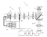
- FIG. 1 is a configuration diagram of the structured illumination microscope apparatus 1.
- the structured illumination microscope apparatus 1 includes a laser unit 100, an optical fiber 11, an illumination optical system 10, an imaging optical system 30, an imaging element 42, a control device 43, an image storage / An arithmetic device 44 and an image display device 45 are provided.
- the illumination optical system 10 is an epi-illumination type, and the sample 2 is illuminated using the objective lens 31 and the dichroic mirror 33 of the imaging optical system 30.
- the laser unit 100 includes a first laser light source 101, a second laser light source 102, shutters 103 and 104, a mirror 105, a dichroic mirror 106, and a lens 107.
- Each of the first laser light source 101 and the second laser light source 102 is a coherent light source, and the emission wavelengths thereof are different from each other.
- the wavelength ⁇ 1 of the first laser light source 101 is longer than the wavelength ⁇ 2 of the second laser light source 102 ( ⁇ 1> ⁇ 2).
- the first laser light source 101, the second laser light source 102, and the shutters 103 and 104 are driven by the control device 43, respectively.
- the optical fiber 11 is composed of, for example, a polarization-preserving single mode fiber in order to guide the laser light emitted from the laser unit 100.
- the position of the output end of the optical fiber 11 in the optical axis direction can be adjusted by the position adjusting mechanism 11A.
- This position adjustment mechanism 11 ⁇ / b> A is driven by the control device 43.
- the illumination optical system 10 includes, in order from the emission end side of the optical fiber 11, a collector lens 12, a polarizing plate 13, a light beam branching unit 14, a condensing lens 17, a light beam selecting unit 18, a lens 21, and a field of view.
- a diaphragm 22, a field lens 23, an excitation filter 24, a dichroic mirror 33, and an objective lens 31 are disposed.
- the light beam branching unit 14 includes a translation mechanism 15 and a diffractive optical element (diffraction grating) 16.
- the light beam selection unit 18 includes a half-wave plate 19, a light beam selection member 20, and a rotation mechanism 18A. And are provided. Each of the beam splitter 14 and the beam selector 18 is driven by the control device 43.
- an objective lens 31 In the imaging optical system 30, an objective lens 31, a dichroic mirror 33, an absorption filter 34, and a second objective lens 35 are arranged in this order from the sample 2 side.
- Specimen 2 is, for example, a culture solution dropped on a parallel plate-like glass surface, and fluorescent cells exist in the vicinity of the glass interface in the culture solution. In this cell, both the first fluorescent region excited by light of wavelength ⁇ 1 and the second fluorescent region excited by light of wavelength ⁇ 2 are expressed.
- the image sensor 42 is a two-dimensional image sensor composed of a CCD, a CMOS, or the like.
- the image sensor 42 captures an image formed on the imaging surface 41 and generates an image. This image is taken into the image storage / arithmetic unit 44 via the control unit 43.
- the control device 43 drives and controls the laser unit 100, the position adjustment mechanism 11A, the light beam branching unit 14, the light beam selecting unit 18, and the image sensor 42.
- the image storage / arithmetic unit 44 performs a calculation on the image given through the control unit 43, stores the calculated image in an internal memory (not shown), and sends it to the image display unit 45.
- the laser light having a wavelength ⁇ 1 (first laser light) emitted from the first laser light source 101 is incident on the mirror 105 via the shutter 103, it reflects off the mirror 105 and enters the dichroic mirror 106.
- the laser light having the wavelength ⁇ 2 (second laser light) emitted from the second laser light source 102 enters the beam splitter 106 via the shutter 104 and is integrated with the first laser light.
- the first laser beam and the second laser beam emitted from the dichroic mirror 106 enter the incident end of the optical fiber 11 through the lens 107.
- the laser light incident on the incident end of the optical fiber 11 propagates inside the optical fiber 11 to generate a point light source at the output end of the optical fiber 11.
- the laser light emitted from the point light source is converted into a parallel light beam by the collector lens 12 and is incident on the diffraction grating 16 of the light beam branching section 14 via the polarizing plate 13 and is branched into diffracted light beams of respective orders.
- the diffracted light beams of these orders are condensed at different positions on the pupil conjugate plane 25 by the condenser lens 17.
- the pupil conjugate plane 25 is the focal position (rear focal position) of the lens 17, and the lens 23 and the lens 21 are arranged with respect to the pupil 32 of the objective lens 31 (the position where the ⁇ first-order diffracted light is condensed).
- the concept of “conjugate position” is determined by a person skilled in the art in consideration of design-related matters such as aberration and vignetting of the objective lens 17 and the lenses 21 and 23. The position was also included.
- the polarizing plate 13 can be omitted, but it is effective for reliably cutting off the excess polarization component. Further, in order to increase the utilization efficiency of the laser light, it is desirable that the axis of the polarizing plate 13 coincides with the polarization direction of the laser light emitted from the optical fiber 11.
- the diffracted light beams of respective orders toward the pupil conjugate plane 25 are incident on the light beam selector 18 disposed in the vicinity of the pupil conjugate plane 25.
- the light beam selection unit 18 selectively passes only one pair of diffracted light beams (here, only ⁇ 1st order diffracted light beams) among the incident diffracted light beams of each order.
- the ⁇ 1st-order diffracted light beam that has passed through the light beam selector 18 is converted into parallel light by the field lens 23 after forming a plane conjugate with the diffraction grating 16 near the field stop 22 by the lens 21, and further passes through the excitation filter 24.
- Each of the ⁇ first-order diffracted light beams collected on the pupil surface 32 becomes a parallel light beam when emitted from the tip of the objective lens 31 and overlaps with each other on the surface of the sample 2 to form interference fringes.
- This interference fringe is used as structured illumination light.
- the modulated image is imaged by the image sensor 42 and taken into the image storage / arithmetic unit 44 via the control unit 43. Further, the captured modulated image is subjected to demodulation calculation (details will be described later) in the image storage / arithmetic unit 44 to generate a demodulated image (super-resolution image).
- the super-resolution image is stored in an internal memory (not shown) of the image storage / arithmetic unit 44 and is sent to the image display unit 45.
- FIG. 2 is a diagram for explaining the light beam branching portion 14
- FIG. 2A is a view of the diffraction grating 16 of the light beam branching portion 14 as seen from the optical axis direction
- FIG. 2B is ⁇ 1 It is a figure which shows the positional relationship of the condensing point which a next diffracted light beam forms in a pupil conjugate plane.
- 2A is a schematic diagram, the structure period of the diffraction grating 16 illustrated in FIG. 2A is not necessarily the same as the actual structure period.
- the diffraction grating 16 is a two-dimensional diffraction grating having a periodic structure in a plurality of different directions perpendicular to the optical axis of the illumination optical system 10.
- the diffraction grating 16 has a periodic structure in each of the first direction V1, the second direction V2, and the third direction V3, which are different by 120 °, and the period (pitch) of these periodic structures is common. Assume.
- the periodic structure of the diffraction grating 16 is either a concentration type periodic structure formed using density (transmittance) or a phase type periodic structure formed using steps (phase difference).
- the phase difference type periodic structure is preferable in that the diffraction efficiency of the + 1st order diffracted light is higher.
- Such parallel light beams incident on the diffraction grating 16 are divided into a first diffracted light beam group branched in the first direction V1, a second diffracted light beam group branched in the second direction V2, and a third light beam branched in the third direction V3. It is converted into a diffracted light beam group.
- the first diffracted light beam group includes a 0th-order diffracted light beam and a ⁇ 1st-order diffracted light beam, and of these, the ⁇ 1st-order diffracted light beams having common orders travel in a symmetric direction with respect to the optical axis.
- the second diffracted light beam group includes a 0th-order diffracted light beam and a ⁇ 1st-order diffracted light beam, and the ⁇ 1st-order diffracted light beam having a common order travels in a symmetric direction with respect to the optical axis. .
- the third diffracted light beam group includes a 0th-order diffracted light beam and a ⁇ 1st-order diffracted light beam, and the ⁇ 1st-order diffracted light beam having a common order travels in a symmetric direction with respect to the optical axis. .
- the ⁇ 1st order diffracted light beam of the first diffracted light beam group, the ⁇ 1st order diffracted light beam of the second diffracted light beam group, and the ⁇ 1st order diffracted light beam of the third diffracted light beam group are brought into the pupil conjugate plane by the condenser lens 17 described above. Are condensed at different positions.
- the condensing points 25d and 25g of the ⁇ first-order diffracted light beams of the first diffracted light beam group are symmetric with respect to the optical axis, and the arrangement direction of the condensing points 25d and 25g is the first. This corresponds to one direction V1.
- the condensing points 25c and 25f of the ⁇ 1st-order diffracted light beams of the second diffracted light beam group are symmetrical with respect to the optical axis, and the arrangement direction of the condensing points 25c and 25f corresponds to the second direction V2.
- the amount of deviation of the condensing points 25c and 25f of the second diffracted light beam group is the same as the amount of deviation of the condensing points 25d and 25g of the first diffracted light beam group.
- the condensing points 25b and 25e of the ⁇ 1st-order diffracted light beams of the third diffracted light beam group are symmetrical with respect to the optical axis, and the arrangement direction of the condensing points 25b and 25e corresponds to the third direction V3. Note that the amount of deviation of the condensing points 25b and 25e of the third light flux group is the same as the amount of deviation of the condensing points 25d and 25g of the first diffracted light flux group.
- the translation mechanism 15 is composed of a piezo motor or the like.
- the translation mechanism 15 is a direction perpendicular to the optical axis of the illumination optical system 10 and is perpendicular to the first direction V1, the second direction V2, and the third direction V3 described above. Is translated.
- the diffraction grating 16 is translated in this direction, the fringe phase of the structured illumination light shifts (details will be described later).
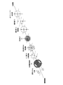
- 3 and 4 are diagrams for explaining the light beam selector 18.
- the half-wave plate 19 of the light beam selection unit 18 sets the polarization direction of the incident diffracted light beam of each order
- the light beam selection member 20 of the light beam selection unit 18 is This is a mask that selectively allows only one group of ⁇ first-order diffracted light beams to pass through among the first to third diffracted light beam groups.
- a rotation mechanism (not shown) of the light beam selection unit 18 rotates the light beam selection member 20 around the optical axis, thereby changing the selected ⁇ first-order diffracted light beam between the first to third diffracted light beam groups.
- the half-wave plate 19 is rotated around the optical axis in conjunction with the light beam selection member 20 to change the polarization direction when the selected ⁇ 1st-order diffracted light beams are incident on the sample 2. Keep polarized.
- the light beam selector 18 switches the stripe direction of the structured illumination light while maintaining the stripe state of the structured illumination light.
- the conditions for maintaining the stripe state will be specifically described.
- the direction of the fast axis (fast axis) of the half-wave plate 19 is ⁇ with respect to the ⁇ 1st-order diffracted light beam branching direction (any one of the first direction V1 to the third direction V3). It is necessary to set the polarization direction of the first-order diffracted light beam to be vertical.
- the fast axis of the half-wave plate 19 is a direction in which the amount of phase delay when light polarized in the direction of the axis passes through the half-wave plate 19 is minimized. It is.
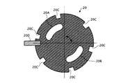
- the opening pattern of the light beam selection member 20 includes a first opening portion 20A and a second opening portion 20B through which one and the other of ⁇ first-order diffracted light beams belonging to the same diffracted light beam group are individually passed.
- the length of each of the first opening 20A and the second opening 20B around the optical axis is set to a length that allows the diffracted light beam linearly polarized in the above-described direction to pass therethrough. Therefore, the shape of each of the first opening 20A and the second opening 20B is a shape close to a partial ring shape.
- first reference position the rotation position of the half-wave plate 19 when the direction of the fast axis of the half-wave plate 19 is parallel to the direction of the axis of the polarizing plate 13
- the amount of rotation of the half-wave plate 19 from the first reference position is controlled to one half of the amount of rotation of the light beam selection member 20 from the second reference position. It should be.
- the rotation amount of the half-wave plate 19 from the first reference position is ⁇ / 2
- the rotation amount of the light beam selection member 20 from the second reference position is set to ⁇ .
- the rotation mechanism 18A of the light beam selection unit 18 selects the first-order diffracted light beam (the branch direction is the first direction V1) of the first diffracted light beam group, as shown in FIG.
- the light beam selection direction of the selection member 20 is rotated rightward from the second reference position by the rotation angle ⁇ 1
- the fast axis direction of the half-wave plate 19 is rotated rightward from the first reference position. Rotate by angle ⁇ 1 / 2.
- the polarization direction of the diffracted light beam of each order before passing through the half-wave plate 19 is parallel to the direction of the axis of the polarizing plate 13 as indicated by a broken line double arrow in FIG.
- the polarization direction of each order diffracted light beam after passing through the half-wave plate 19 is rotated to the right by the rotation angle ⁇ 1
- the polarization direction of the selected ⁇ 1st order diffracted light beam is As indicated by a solid double-pointed arrow in FIG. 4A, the ⁇ first-order diffracted light beams are perpendicular to the branching direction (first direction V1).
- the rotation mechanism 18A of the light beam selector 18 selects the ⁇ first-order diffracted light beam (the branch direction is the second direction V2) of the second diffracted light beam group, as shown in FIG.
- the light beam selection direction of the selection member 20 is rotated rightward from the second reference position by the rotation angle ⁇ 2
- the fast axis direction of the half-wave plate 19 is rotated rightward from the first reference position. Rotate by angle ⁇ 2 / 2.
- the polarization directions of the diffracted light beams of the respective orders before passing through the half-wave plate 19 are parallel to the direction of the axis of the polarizing plate 13 as indicated by the broken line in FIG. 4B.
- the polarization direction of each order of the diffracted light beam after passing through the half-wave plate 19 is rotated to the right by the rotation angle ⁇ 2, so the polarization direction of the selected ⁇ 1st order diffracted light beam is As shown by the solid line double arrow in FIG. 4B, these are perpendicular to the branching direction (second direction V2) of the ⁇ first-order diffracted light beams.
- the rotation mechanism 18A of the light beam selector 18 selects the ⁇ first-order diffracted light beam (the branch direction is the third direction V3) of the third diffracted light beam group, as shown in FIG.
- the light beam selection direction of the selection member 20 is rotated from the second reference position to the left (seen from the sample side; hereinafter the same) by the rotation angle ⁇ 3
- the direction of the fast axis of the half-wave plate 19 is
- the first reference position is rotated to the left by the rotation angle ⁇ 3 / 2.
- the polarization direction of the diffracted light beam of each order before passing through the half-wave plate 19 is parallel to the direction of the axis of the polarizing plate 13 as shown by the broken line in FIG. 4C.
- the polarization directions of the diffracted light beams of the respective orders after passing through the half-wave plate 19 are rotated to the left by the rotation angle ⁇ 3. Therefore, the polarization directions of the selected ⁇ 1st order diffracted light beams are As shown by the actual double-headed arrow in FIG. 4C, these are perpendicular to the branching direction (third direction V3) of the ⁇ first-order diffracted beams.
- the rotation mechanism 18A of the light beam selection unit 18 only needs to interlock the half-wave plate 19 and the light beam selection member 20 with a gear ratio of 2: 1.
- FIG. 5 is a diagram illustrating the function of the light beam selection unit 18 described above.
- a double arrow surrounded by a circular frame indicates the polarization direction of the light beam
- a double arrow surrounded by a square frame indicates the axial direction of the optical element.
- a plurality of (six in the example shown in FIG. 6) notches 20C are formed on the outer peripheral portion of the light flux selecting member 20, and the rotation mechanism 18A includes these notches 20C.
- a timing sensor 20D for detecting the notch 20C is provided.
- the rotation mechanism 18A can detect the rotation position of the light beam selector 18 and thus the rotation position of the half-wave plate 19.
- FIG. 7 is a diagram for explaining the operation of the translation mechanism 15 of the light beam branching section 14.
- the modulated image generated by the structured illumination microscope apparatus 1 includes, in the structure of the sample 2, the 0th order modulation component, the + 1st order modulation component, which is the structure information whose spatial frequency is modulated by the structured illumination light, ⁇ 1
- the next modulation component is superimposed, and the three unknown parameters superimposed on each other need to be made known by demodulation calculation (details will be described later).
- the translation mechanism 15 of the light beam splitting unit 14 is in a direction perpendicular to the optical axis of the illumination optical system 10 as shown in FIG.
- the diffraction grating 16 is shifted in a non-perpendicular direction (x direction) with respect to all of the one direction V1, the second direction V2, and the third direction V3.
- the shift amount L of the diffraction grating 16 necessary for shifting the phase of the interference fringes by a desired shift amount ⁇ is the same as when the light beam selection direction by the light beam selection unit 18 is the first direction V1 and in the second direction V2. And when in the third direction V3 are not necessarily the same.
- the structural period (pitch) of each of the first direction V1, the second direction V2, and the third direction V3 of the diffraction grating 16 is P, and the shift direction (x direction) of the diffraction grating 13 is set.
- the first direction V1 is ⁇ 1
- the angle between the shift direction (x direction) of the diffraction grating 16 and the second direction V2 is ⁇ 2, and the shift direction (x direction) of the diffraction grating 16 and the first direction V1
- a required shift amount L3 of the diffraction grating 16 in the x direction when the selected direction is the third direction V3.
- L3 ⁇ ⁇ P / represented by (4 ⁇ ⁇
- the shift amount L in the x direction of the diffraction grating 16 necessary for setting the phase shift amount of the interference fringes to a desired value ⁇ is the wavelength selection direction (the first direction V1, the second direction V2, and the third direction V3). Any one) and the angle ⁇ formed by the x direction are expressed as shown in Expression (1).
- the shift amount L in the x direction of the diffraction grating 16 necessary for setting the phase shift amount ⁇ of the interference fringes to 2 ⁇ is P / (2 ⁇
- the image storage / arithmetic unit 44 described above is configured by a computer that performs calculations by executing a calculation program, an arithmetic circuit that performs arithmetic processing, or a combination of both.
- the computer may be a general-purpose computer in which a calculation program is installed via a storage medium or a communication network.
- the basic procedure consists of the following four steps.
- Each of a plurality of modulated images is Fourier transformed to generate a plurality of spatial frequency spectra.
- Second step The zero-order modulation component of fluorescence, the first-order modulation component of fluorescence, and the first-order modulation component of fluorescence superimposed on individual spatial frequency spectra are separated from each other in Fourier space.
- the spatial frequency spectrum of the demodulated image is generated by rearranging the zero-order modulation component, the fluorescence first-order modulation component, and the fluorescence first-order modulation component separated from each other in Fourier space. .
- the interference fringes projected onto the sample 2 are two-beam interference fringes (that is, the example in which the structured illumination microscope apparatus 1 is used in the 2D-SIM mode), but the interference fringes projected onto the sample 2 Can be made into a three-beam interference fringe (that is, the structured illumination microscope apparatus 1 is used in the 3D-SIM mode).
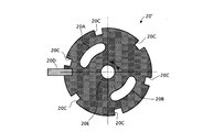
- a light beam selection member 20 'as shown in FIG. 8 is used instead of the light beam selection member 20 shown in FIG.
- This light beam selection member 20 ' is the same as the light beam selection member 20 shown in FIG. 6, but is provided with an opening 20E for passing the 0th-order diffracted light beam.
- the opening 20E is formed in the vicinity of the optical axis, and the shape of the opening 20E is, for example, a circle. According to such a light beam selection member 20 ', not only the ⁇ 1st order diffracted light beam but also the 0th order diffracted light beam can contribute to the interference fringes.
- the interference fringes generated by the interference of the three diffracted light beams are spatially modulated not only in the surface direction of the sample 2 but also in the depth direction of the sample 2. Therefore, according to the interference fringes, a super-resolution effect can be obtained also in the depth direction of the sample 2.
- the contents of the demodulation operation to be executed by the image storage / arithmetic unit 44 are different between the 2D-SIM mode and the 3D-SIM mode. This is because, in the modulation image generated in the 2D-SIM mode, three components of the fluorescence zero-order modulation component, the fluorescence plus first-order modulation component, and the fluorescence minus first-order modulation component are superimposed.
- the modulated image generated in the SIM mode includes 5th order of the 0th order modulation component of fluorescence, the 1st order modulation component of fluorescence, the 1st order modulation component of fluorescence, the + 2nd order modulation component of fluorescence, and the 2nd order modulation component of fluorescence This is because the components are superimposed.
- the number of modulation components to be superimposed on the modulated image is different between the 2D-SIM mode and the 3D-SIM mode, the number of frames of the modulated image to be acquired by the control device 43 is also different. This will be described in detail below.
- interference fringe intensity distribution in the 2D-SIM mode is defined as follows.
- the fluorescence intensity distribution I fl (x) is expressed as follows.
- the modulated image represented in Fourier space (that is, the spatial frequency spectrum of the modulated image) is represented as follows.
- the interference fringe intensity distribution of 2D-SIM is expressed as follows (the fringes have a sinusoidal intensity distribution).
- ⁇ 0 is the spatial frequency (modulation frequency) of the interference fringes.
- ⁇ is a coordinate in Fourier space.
- Equation 1.6 Equation 1.3, and Equation 1.4, it can be seen that the modulated image in the Fourier space is expressed as follows.
- the spatial frequency spectrum in the Fourier space is simply referred to as “spectrum”. Further, the corresponding subscript “ ⁇ i ” is attached to the modulated image acquired when the phase of the interference fringes is ⁇ i .
- Equation 1.7 a fluorescence first-order modulation component, a fluorescence first-order modulation component, and a fluorescence zero-order modulation component.
- Three terms on the right side of Equation 1.7 correspond to each of these modulation components. That is, since the sample (fluorescence) is spatially modulated with stripes having a sinusoidal intensity distribution, the spectrum of the modulation image can be expressed by three modulation components (0th order modulation component and ⁇ 1st order modulation component) of fluorescence. it can.
- the + 1st order modulation component superimposed on the observation point ⁇ is a value (restoration value) that the restoration point ( ⁇ 0 ) should have in the spectrum of the demodulated image
- the ⁇ 1st order modulation component superimposed on the observation point ⁇ is The value (restoration value) that the restoration point ( ⁇ + ⁇ 0 ) in the spectrum of the demodulated image should have
- the zero-order modulation component superimposed on the observation point ⁇ is the value (restoration) that the restoration point ⁇ in the spectrum of the demodulation image should have. Value). This is true for each observation point in the spectrum of the modulated image.
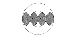
- a large black spot in FIG. 9 corresponds to a certain observation point, and a large black spot and two small black spots on both sides thereof correspond to three restoration points restored from the observation point.
- the spatial frequency (modulation frequency) ⁇ 0 of the fringes in the conventional 2D-SIM is set so that
- ⁇ 2NA is A restoration value of a restoration point that satisfies
- FIG. 10 shows the distribution of the reciprocal of the condition number of the matrix M.
- the first phase phi 1 0 ° of the modulated image Distant
- the phase phi 3 of the phase phi 2 and the third modulated image of the second modulation image as a variable.
- the first-order modulation component of fluorescence superimposed on the observation point ⁇ and the zero-order modulation component of fluorescence superimposed on the observation point ( ⁇ + ⁇ 0 ) are both restored to the restoration point ( ⁇ + ⁇ 0 ).
- the fluorescence first-order modulation component superimposed on the observation point ( ⁇ + ⁇ 0 ) and the fluorescence zero-order modulation component superimposed on the observation point ⁇ both correspond to the restoration value of the restoration point ⁇ . That is, these two observation points ⁇ and ( ⁇ + ⁇ 0 ) include the restoration values of the two common restoration points ⁇ and ( ⁇ + ⁇ 0 ). This relationship is used in the two-image two-point restoration in this section. This will be specifically described below.
- the interference fringe intensity distribution is the same as that of the conventional 2D-SIM, the observation range of the spectrum of the modulated image is represented by
- the spatial frequency (modulation frequency) ⁇ 0 of the stripes in this section is set so that
- the spatial frequency (modulation frequency) ⁇ 0 of the fringes is set by the grating pitch of the diffraction grating 16 (the fringe pitch formed on the specimen).
- observation values of two observation points ⁇ and ( ⁇ + ⁇ 0 ) separated by ⁇ 0 can be obtained from the spectrum of one modulated image.
- the observed value of ( ⁇ + ⁇ 0 ) can be obtained only in a range where ⁇ satisfies
- the observed value at the observation point ⁇ and the observed value at the observation point ( ⁇ + ⁇ 0 ) in the spectrum of one modulated image are expressed by the following equations.
- the restoration values (unknown numbers) of the four restoration points appear on the right side of these expressions 1.12 and 1.13. In order to make these four restoration values known, two more equations are necessary.
- each spectrum of two modulated images having different phases ⁇ is generated, and a total of four observation values relating to two observation points ⁇ and ( ⁇ + ⁇ 0 ) are referred to from each of the two spectra.
- a total of four expressions including four restoration values are obtained.
- ⁇ 1 OTF ( ⁇ )
- ⁇ 2 OTF ( ⁇ + ⁇ 0 )
- the phase ⁇ of the first modulated image is ⁇ 1
- the phase ⁇ of the second modulated image is ⁇ If 2 is set, the four equations are represented by the following matrix.
- the inner circular frame is the outer edge (
- 2NA) of the normal resolution range.
- the outer circular frame is the outer edge (
- 4NA) of the super-resolution range.
- the two large black dots in FIG. 11 indicate two observation points that are shifted by the spatial frequency (modulation frequency) ⁇ 0 of the stripes.
- the two large black dots and the two small black dots in FIG. Four restoration points restored from two observation points are shown.
- the restoration values of the entire filled area in FIG. 11 are obtained by repeating the calculation of the four restoration values while moving the two observation points within the normal resolution range.
- the determinant of the matrix M may take a value other than zero.
- the determinant of the matrix M is expressed as follows.
- phase phi 1 of the first modulated image the phase difference [Delta] [phi between the phase phi 2 of the second modulation image, if only a ⁇ ⁇ 0, detM ⁇ 0, and the equation 1.14 is uniquely Have a good solution.
- the condition necessary for the demodulation operation in section 1.3 is ⁇ ⁇ 0.
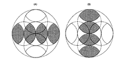
- the painted area in FIG. 12A is a recoverable range when ⁇ ⁇ ⁇
- , whereas the filled area in FIG. 12B is a recoverable range when ⁇ ⁇ ( In either case,
- 2NA.)
- the inner circle is the outer edge of the normal resolution range (
- 2NA)
- the outer circle is the outer edge of the super-resolution range (
- 4NA).
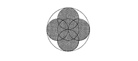
- the number of directions of interference fringes is 1. However, if the number of directions of interference fringes is 3, and the same demodulation operation as in section 1.3 is applied to each direction, as shown in FIG. A wide area can be restored.
- Two-pass restoration will be described as a demodulation operation of the 2D-SIM of this embodiment.
- the number of interference fringe directions is set to two.
- each interference fringe is represented by a wave vector.
- the magnitude of this wave vector indicates the magnitude of the spatial frequency of the interference fringes, and the direction of the wave vector indicates the direction of the interference fringes.
- First step Two modulated images having a wave vector of ⁇ 0 and different phases are acquired, and a spectrum of each of the two modulated images is generated. Each of these two modulated images is represented as follows.
- the restoration value of the region shown in FIG. 14A is obtained by performing the same demodulation operation as in section 1.3 on the spectrum of each of the two modulated images.
- Second step Two modulated images having a wave vector of ⁇ 1 and different phases are acquired, and respective spectra of the two modulated images are generated. Each of these two modulated images is represented as follows.
- the restoration value of the region shown in FIG. 14B is obtained by performing the same demodulation operation as in section 1.3 on the spectrum of each of the two modulated images.
- the first step and the third step can be collectively expressed as shown in FIG. That is, the four black dots connected in the horizontal direction on the horizontal line in FIG. 16B are in Fourier space (wave number space) of four restoration values (unknown numbers) obtained from simultaneous equations equivalent to the expression 1.14 solved in the first step. Represents the position.
- the large black dot at the center is one known number of Fourier spaces (wave number space) obtained from the expression of the first step.
- the small black dots at both ends indicate the positions in the Fourier space (wave number space) of the two restored values (unknown numbers) of the simultaneous equations 1.26 solved in the third step.
- the mutual positional relationship between these eight black spots is the same regardless of which example is selected.
- the range of positions where black spots can be taken in Fourier space (wave number space) is limited by the range of positions where two large black spots (center) can be taken in Fourier space (wave number space). Since the range of positions that can be taken by the two large black dots is
- FIG. 16A shows the second step and the fourth step in the same manner as FIG. 16B.
- two-pass restoration is performed with emphasis on suppressing the number of modulated images (number of spectra). Therefore, in the first example, the number of directions of the wave vector is set to 2, and two modulated images having different phases are obtained for each of two wave vector ⁇ 1 and ⁇ 2 different from each other (a total of four modulated images). An image is acquired) and the spectrum of each of the four modulated images is generated (a total of four spectra are generated).
- the phase difference ⁇ between two modulated images acquired with the same wave vector is set to ⁇ ⁇ ⁇ .
- is set to
- the number of directions of the wave vector is assumed to be 3 (modulated images are acquired from each of the three wave vector ⁇ 1 , ⁇ 2 , ⁇ 3 , and respective spectra of these modulated images are generated).
- the number of phases is 2 (two modulated images I (0) and I (1) having the same fringe direction and different phases. However, in each of the other two directions (wave vector ⁇ 2 , ⁇ 3 ), the number of phases is suppressed to 1 (two modulated images I (2) and I (3) having different fringe directions are obtained. ).
- each wave vector is set to
- FIG. 19 is an illustration of the calculation. However,
- and ⁇ 1 ⁇ ⁇ 2
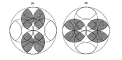
- the three large black dots in FIG. 19A indicate the three observation points located at the vertices of the triangle drawn by the three wave vector ⁇ 1 , ⁇ 2 , ⁇ 3 in the spectrum of the modulated image.
- Three large black spots and nine small black spots in A) indicate restoration points (a total of 12 restoration points) restored from these three observation points.
- FIG. 19B is an illustration when the same restoration is performed by inverting the direction of the triangle.
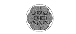
- the restoration in FIG. 19A and the restoration in FIG. 19B can be performed in parallel. In this section, these two types of restoration are performed, and the entire filled area shown in FIG. 20 is restored.
- FIG. 20 is a combination of the restoration area shown in FIG. 19A and the restoration area shown in FIG.
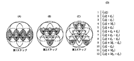
- FIG. 21 is a diagram illustrating the calculation in this section divided into three steps.
- FIG. 21A shows four restoration points 1 to 4 restored in the first step.
- FIG. 21B shows four restoration points 5 to 8 restored in the second step.
- FIG. 21C shows the four restoration points 9 to 12 restored in the third step.
- FIG. 21D shows the correspondence between the numbers 1 to 12 in the figure and the restoration values. .
- First step By applying four observation values regarding two observation points 1 and 2 arranged in the direction of the wave vector ⁇ 1 at an interval
- Second step Using the respective restoration values of the restoration points 1 and 2 , four restoration points 5, 6, 7, and 8 that are shifted from the restoration points 1 and 2 by the wave number vectors ⁇ 2 and ⁇ 3 . Each restoration value is obtained.
- the equations used in this case are two equations (for two phases) relating to the direction of the wave vector ⁇ 1 , one equation relating to the direction of the wave vector ⁇ 2 , one equation relating to the direction of the wave vector ⁇ 3 , There are a total of four equations.
- Third step Using the restoration values of the restoration points 1, 2, 5 respectively, the remaining restoration points 9, 10, which are shifted from the restoration points 1, 2 , 5 by the wave vector ⁇ 2 , ⁇ 3 , The restoration values of 11 and 12 are obtained.
- the formula used in this case the two expressions (observation point 2 min) with respect to the direction of wave vector xi] 2, and two equations for the direction of the wave vector xi] 3 (observation point 2 min), total 4 Is one expression.
- the number of phases in all three directions is limited to 1, and instead, one unmodulated image is acquired and the spectrum of the unmodulated image is generated.
- the spectrum of the unmodulated image is a Fourier transform of the unmodulated image.
- the number of modulated images (the number of modulated image spectra) is 3, and the number of unmodulated images (the number of unmodulated image spectra) is 1, so a total of 12 observations from three observation points. The value is obtained.
- the restoration value of the restoration point is obtained individually.
- the interference fringes projected onto the specimen are the sum of three interference fringes with different directions as follows (three-way interference fringes). A method for projecting the three-way interference fringes will be described later.
- a certain observation point ⁇ in the spectrum of the modulated image has a zero-order modulation component of the fluorescence, a ⁇ first-order modulation component of the fluorescence by the wave vector ⁇ 1 , and a ⁇ first-order modulation component of the fluorescence by the wave vector ⁇ 2. And a total of seven components of the fluorescence ⁇ first-order modulation component by the wave vector ⁇ 3 are superimposed.
- the whole of these three observation points ⁇ , ( ⁇ + ⁇ 1 ), ( ⁇ + ⁇ 2 ) includes the restoration values of 12 restoration points.
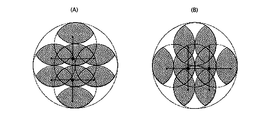
- FIG. 22 is an illustration thereof. However,
- and ⁇ 1 ⁇ ⁇ 2
- the three large black dots in FIG. 22A indicate the three observation points located at the vertices of the triangle drawn by the three wave vector ⁇ 1 , ⁇ 2 , ⁇ 3 in the spectrum of the modulated image.
- Three large black spots and nine small black spots in A) indicate restoration points (a total of 12 restoration points) restored from these three observation points.
- FIG. 22B is an illustration when the same restoration is performed by inverting the direction of the triangle.
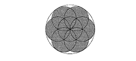
- the restoration in FIG. 22A and the restoration in FIG. 22B can be performed in parallel. In this section, these two types of restoration are performed, and the same area as the filled area shown in FIG. 20 is restored.
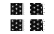
- the phases (consisting of three components) of the three-way interference fringes reflected in each of the four modulated images I (1) , I (2) , I (3) , and I (4 ) are, for example,
- the interference fringe intensity distribution in each of the four modulated images I (1) , I (2) , I (3) , and I (4) is as follows.
- the sum of the interference fringe intensity distributions in the four modulated images is as follows.
- each part of the specimen is illuminated with the same amount of light.
- the patterns of the three-way interference fringes are common, and only the pattern positions are shifted. Therefore, the following relationship holds.
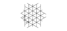
- FIG. 23 is a diagram showing the relationship between the lattice structure of three-way interference fringes and the basic vectors a 1 and a 2 of the lattice.
- FIG. 24 is a diagram showing the relationship of the interference fringe intensity distribution among the four modulated images.
- the lattice patterns are moved in parallel so as not to overlap each other between the four modulated images.
- the unit of the movement amount is half of the basic vector of the lattice.
- the diffraction grating 16 (FIG. 2A) described above is formed as in the case of generating other interference fringes (one-way interference fringes). Can be used.
- the aperture pattern of the light beam selection member 20 includes the 0th order diffracted light of each group, the second and higher order diffracted lights of each group, and the + 1st order diffracted light of each group. And is set so as to transmit only the ⁇ 1st order diffracted light of each group.
- the condensing points formed on the pupil plane are only the condensing points by the three ⁇ 1st order diffracted lights.
- FIG. 25A shows the arrangement of the condensing points in the case where excess diffracted light is not cut by the light beam selecting member 20, and FIG. The arrangement
- three condensing points are formed at positions shifted by 120 °.
- Three diffracted lights (here, three ⁇ 1st order diffracted lights) emitted from these three condensing points enter the illumination area of the specimen from three directions, and form three-way interference fringes on the specimen.
- the diffracted light contributing to the interference fringes is three ⁇ 1st order diffracted lights here, it goes without saying that the three + 1st order diffracted lights may be used.
- each of the laser light emitted from the laser light source A, the laser light emitted from the laser light source B, and the laser light emitted from the laser light source C is split into two branched fibers.
- the point light sources a and a ′ are coherent light sources generated from the laser light source A
- the point light sources b and b ′ are coherent light sources generated from the laser light source B
- the point light sources c and c ′ is a coherent light source generated from the laser light source C.
- the six laser lights emitted from these six point light sources are incident on the specimen illumination area from six directions, and form three-way interference fringes on the specimen.
- the laser beams La and La ′ emitted from the point light sources a and a ′, the laser beams Lb and Lb ′ emitted from the point light sources b and b ′, and the laser beams Lc emitted from the point light sources c and c ′, Lc ′ does not interfere with each other. Accordingly, the interference fringes formed on the specimen are a superposition of three types of two-beam interference fringes. Therefore, the super-resolution effect is not lowered and the utilization efficiency of the laser light is high.
- the diffraction grating 16 is translated in order to change the phase of the three-way interference fringe (consisting of three components). Instead of moving, the phase difference between the laser beams La and a ′, the phase difference between the laser beams Lb and Lb ′, and the phase difference between the laser beams Lc and Lc may be changed.
- the interference fringe intensity distribution in the 3D-SIM is assumed as follows.
- the interference fringe intensity distribution K (r) in the 3D-SIM is expressed as follows.
- the interference fringe intensity distribution K is expressed as follows.
- the fringes are first-period fringes having a sinusoidal intensity distribution (interference fringes due to left and right light among the three light beams consisting of the central light and its left and right lights), and a second having a sinusoidal intensity distribution. It consists of a fringe with a cycle (twice the first cycle) (interference fringes due to the center light and the right light (or left light) among the three light beams consisting of the center light and its left and right lights) superimposed.
- the fluorescent intensity distribution of the sample is I 0 (r) K (r). Assuming that it is expressed, the approximation that the fluorescence generated at each point of the sample does not excite the fluorescent substance at other points (Born approximation) is adopted.
- the modulated image I (x, z) acquired in the 3D-SIM mode is expressed as follows.
- the modulated image represented in Fourier space that is, the spatial frequency spectrum of the modulated image
- the modulated image represented in Fourier space that is, the spatial frequency spectrum of the modulated image
- a, b, and c are values determined by the intensity balance of the three light beams ( ⁇ first-order diffracted light and zero-order diffracted light) that contribute to the interference fringes of the 3D-SIM.
- the observation point ⁇ in the spectrum of the modulated image acquired in the 3D-SIM mode has a fluorescence first-order modulation component, a fluorescence first-order modulation component, a fluorescence + second-order modulation component, a fluorescence + second-order modulation component, Five components of the fluorescence zero-order modulation component are superimposed.
- the ⁇ first-order modulation component superimposed on the observation point ⁇ is a value (restoration value) that the restoration point ( ⁇ ⁇ ⁇ 0 ) should have in the spectrum of the demodulated image
- the ⁇ second-order modulation component superimposed on the observation point ⁇ Is the value (restoration value) that the restoration point ( ⁇ ⁇ 2 ⁇ 0 ) in the spectrum of the demodulated image should have, and the zero-order modulation component superimposed on the observation point ⁇ should have the restoration point ⁇ in the spectrum of the demodulation image Value (restoration value).
- the ⁇ first-order modulation component superimposed on the observation point ⁇ is a fringe of the second period (twice the first period) having a sinusoidal intensity distribution (three light fluxes consisting of the central light and its left and right lights).
- the ⁇ secondary modulation component superimposed on the observation point ⁇ has a first period having a sinusoidal intensity distribution. It is a component modulated by fringes (interference fringes due to left and right light out of three light beams composed of central light and left and right light).
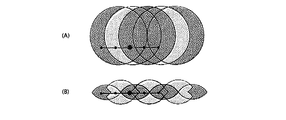
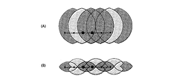
- a large black spot in FIG. 27 corresponds to a certain observation point, and a large black spot and four small black spots on both sides thereof correspond to five restoration points restored from the observation point.
- the first-order modulation component of fluorescence superimposed on the observation point ⁇ and the zero-order modulation component of fluorescence superimposed on the observation point ( ⁇ + ⁇ 0 ) are both restored to the restoration point ( ⁇ + ⁇ 0 ).
- the fluorescent second-order modulation component superimposed on the observation point ⁇ and the fluorescent first modulation component superimposed on the observation point ( ⁇ + ⁇ 0 ) both correspond to the restoration value of the restoration point ( ⁇ + 2 ⁇ 0 ).
- the first-order modulation component of the fluorescence superimposed on the observation point ( ⁇ + ⁇ 0 ) and the zero-order modulation component of the fluorescence superimposed on the observation point ⁇ correspond to the restoration value of the restoration point ⁇
- Both the + 2nd order modulation component of the superimposed fluorescence and the 1st order modulation component of the fluorescence superimposed on the observation point ⁇ correspond to a restored value of ( ⁇ 0 ). That is, these two observation points ⁇ and ( ⁇ + ⁇ 0 ) include the restoration values of four common restoration points ( ⁇ 0 ), ⁇ , ( ⁇ + ⁇ 0 ), and ( ⁇ + 2 ⁇ 0 ).
- the observation value at the observation point ⁇ and the observation value at the observation point ( ⁇ + ⁇ 0 ) are expressed by the following equations.
- FIG. 28 is a diagram showing the frequency range of the 3D-SIM demodulated image in this section.
- 28A is an xy cross section
- FIG. 28B is a zx cross section.
- the above explanation is an explanation of restoration related to a certain wave vector (one direction).
- phase difference ⁇ between the three modulated images acquired with the same wave vector is set to 2 ⁇ / 3.
- the number of directions (number of wave vectors) is 3.
- An unmodulated image is represented as I (0) .
- ⁇ 1st order modulation component and the ⁇ 2nd order modulation component are summarized and expressed as follows.
- the zero-order modulation component (normal resolution component) can be expressed as follows.
- Equation 2.42 first, by applying seven observation values related to the observation point ⁇ in each spectrum of seven modulated images to Equation 2.42, the seven restored values on the right side of Equation 2.42, that is, Are restored ( ⁇ first-order modulation component, ⁇ second-order modulation component, and zero-order modulation component), respectively.
- the modulation component and the ⁇ 1st order modulation component can be separated.
- Equation 2.35 the ⁇ 1st order modulation component is obtained from Equation 2.35.
- the zero-order modulation component and the ⁇ first-order modulation component are separated by fitting the observed values of the 12 modulation image spectra (12 spectra) to this equation.
- Section 1.6 described above may be applied to 3D-SIM as follows.
- the number of directions (number of wave vectors) is 3.
- the number of phases is set to 4, but the number of phases in each of the other two directions is suppressed to 2.
- DESCRIPTION OF SYMBOLS 1 ... Structured illumination microscope apparatus, 100 ... Laser unit, 11 ... Optical fiber, 10 ... Illumination optical system, 30 ... Imaging optical system, 42 ... Imaging device, 43 ... Control apparatus, 44 ... Image storage and calculation apparatus, 45 DESCRIPTION OF SYMBOLS ... Image display apparatus, 12 ... Collector lens, 13 ... Polarizing plate, 14 ... Light beam splitting part, 17 ... Condensing lens, 18 ... Light beam selection part, 21 ... Lens, 22 ... Field stop, 23 ... Field lens, 24 ... Excitation Filter, 33 ... Dichroic mirror, 31 ... Objective lens, 34 ... Absorption filter, 35 ... Second objective lens, 2 ... Sample
Landscapes
- Physics & Mathematics (AREA)
- General Physics & Mathematics (AREA)
- Optics & Photonics (AREA)
- Engineering & Computer Science (AREA)
- Multimedia (AREA)
- Chemical & Material Sciences (AREA)
- Analytical Chemistry (AREA)
- Computer Vision & Pattern Recognition (AREA)
- Microscoopes, Condenser (AREA)
Priority Applications (4)
| Application Number | Priority Date | Filing Date | Title |
|---|---|---|---|
| JP2014525717A JP5888416B2 (ja) | 2012-07-19 | 2013-07-16 | 構造化照明顕微鏡装置 |
| US14/597,495 US10261304B2 (en) | 2012-07-19 | 2015-01-15 | Structured illuminating microscopy apparatus |
| US16/290,149 US11187883B2 (en) | 2012-07-19 | 2019-03-01 | Structured illuminating microscopy apparatus |
| US17/513,391 US20220050283A1 (en) | 2012-07-19 | 2021-10-28 | Structured illuminating microscopy apparatus |
Applications Claiming Priority (2)
| Application Number | Priority Date | Filing Date | Title |
|---|---|---|---|
| JP2012160805 | 2012-07-19 | ||
| JP2012-160805 | 2012-07-19 |
Related Child Applications (1)
| Application Number | Title | Priority Date | Filing Date |
|---|---|---|---|
| US14/597,495 Continuation US10261304B2 (en) | 2012-07-19 | 2015-01-15 | Structured illuminating microscopy apparatus |
Publications (1)
| Publication Number | Publication Date |
|---|---|
| WO2014013720A1 true WO2014013720A1 (fr) | 2014-01-23 |
Family
ID=49948562
Family Applications (1)
| Application Number | Title | Priority Date | Filing Date |
|---|---|---|---|
| PCT/JP2013/004338 Ceased WO2014013720A1 (fr) | 2012-07-19 | 2013-07-16 | Dispositif microscope à éclairage structuré |
Country Status (3)
| Country | Link |
|---|---|
| US (3) | US10261304B2 (fr) |
| JP (1) | JP5888416B2 (fr) |
| WO (1) | WO2014013720A1 (fr) |
Cited By (7)
| Publication number | Priority date | Publication date | Assignee | Title |
|---|---|---|---|---|
| WO2015052936A1 (fr) * | 2013-10-09 | 2015-04-16 | 株式会社ニコン | Dispositif microscope à éclairage structuré |
| WO2015162921A1 (fr) * | 2014-04-25 | 2015-10-29 | 株式会社ニコン | Dispositif microscopique à éclairage structuré et procédé d'observation d'éclairage structuré |
| JP2015212744A (ja) * | 2014-05-02 | 2015-11-26 | オリンパス株式会社 | 標本像データ生成装置、及び、標本像データ生成方法 |
| WO2018096639A1 (fr) * | 2016-11-24 | 2018-05-31 | 株式会社ニコン | Dispositif de traitement d'image, système de microscope, procédé de traitement d'image et programme |
| CN109983767A (zh) * | 2016-11-24 | 2019-07-05 | 株式会社尼康 | 图像处理装置、显微镜系统、图像处理方法及计算机程序 |
| US10900900B2 (en) | 2015-10-19 | 2021-01-26 | Nikon Corporation | Structured illumination microscope, observation method, and storage medium |
| US20230048871A1 (en) * | 2021-08-13 | 2023-02-16 | The Swatch Group Research And Development Ltd | Portable modular unit for inspecting in a timepiece the presence of a lubricating agent or of an epilame |
Families Citing this family (12)
| Publication number | Priority date | Publication date | Assignee | Title |
|---|---|---|---|---|
| JP5900515B2 (ja) * | 2012-01-18 | 2016-04-06 | 株式会社ニコン | 構造化照明装置、構造化照明顕微鏡装置、構造化照明方法 |
| WO2014013720A1 (fr) * | 2012-07-19 | 2014-01-23 | 株式会社ニコン | Dispositif microscope à éclairage structuré |
| JP6635052B2 (ja) * | 2015-02-05 | 2020-01-22 | 株式会社ニコン | 構造化照明顕微鏡、及び観察方法 |
| US10215975B2 (en) * | 2015-02-06 | 2019-02-26 | The Regents Of The University Of Colorado, A Body Corporate | Method and/or system for stabilization, tracking, and/or control of microscopic systems |
| US10989661B2 (en) * | 2015-05-01 | 2021-04-27 | The Board Of Regents Of The University Of Texas System | Uniform and scalable light-sheets generated by extended focusing |
| WO2017180680A1 (fr) | 2016-04-12 | 2017-10-19 | The Board Of Regents Of The University Of Texas System | Microscope à feuille de lumière avec acquisition d'images 3d parallélisées |
| NL2020619B1 (en) * | 2018-01-16 | 2019-07-25 | Illumina Inc | Dual optical grating slide structured illumination imaging |
| CN110044854B (zh) * | 2018-01-16 | 2024-08-02 | 伊鲁米那股份有限公司 | 图样角度空间选择结构照明成像 |
| TWI699559B (zh) * | 2018-01-16 | 2020-07-21 | 美商伊路米納有限公司 | 結構照明成像系統和使用結構化光來創建高解析度圖像的方法 |
| NL2020620B1 (en) * | 2018-01-16 | 2019-07-25 | Illumina Inc | Pattern angle spatial selection structured illumination imaging |
| CN111338070B (zh) * | 2020-03-18 | 2021-04-23 | 中国科学技术大学 | 一种结构光产生装置及结构光照明显微镜 |
| JP7572033B2 (ja) * | 2020-10-23 | 2024-10-23 | 株式会社リガク | 結像型x線顕微鏡 |
Citations (4)
| Publication number | Priority date | Publication date | Assignee | Title |
|---|---|---|---|---|
| JP2009098215A (ja) * | 2007-10-12 | 2009-05-07 | Nikon Corp | 顕微鏡装置、及び顕微鏡装置における位相変化量の算出方法。 |
| JP2009157084A (ja) * | 2007-12-26 | 2009-07-16 | Nikon Corp | 顕微鏡装置 |
| US20120026311A1 (en) * | 2010-04-26 | 2012-02-02 | The Regents Of The University Of California | Structured illumination microscope apparatus and an image forming apparatus |
| JP2012504252A (ja) * | 2008-09-30 | 2012-02-16 | カール ツァイス マイクロイメージング ゲーエムベーハー | 構造化照明を備えた顕微鏡法のための改良された方法および装置 |
Family Cites Families (18)
| Publication number | Priority date | Publication date | Assignee | Title |
|---|---|---|---|---|
| US5489986A (en) * | 1989-02-28 | 1996-02-06 | Nikon Corporation | Position detecting apparatus |
| JPH03140840A (ja) * | 1989-10-26 | 1991-06-14 | Hitachi Ltd | 流動細胞分析装置 |
| US5671085A (en) | 1995-02-03 | 1997-09-23 | The Regents Of The University Of California | Method and apparatus for three-dimensional microscopy with enhanced depth resolution |
| US6259561B1 (en) * | 1999-03-26 | 2001-07-10 | The University Of Rochester | Optical system for diffusing light |
| JP4504037B2 (ja) * | 2004-02-02 | 2010-07-14 | 大日本印刷株式会社 | 光学素子 |
| JP4794839B2 (ja) * | 2004-09-17 | 2011-10-19 | キヤノン株式会社 | 反射型液晶表示装置 |
| EP2082200A2 (fr) * | 2006-10-05 | 2009-07-29 | Delaware State University Foundation, Inc. | Détecteur de son à fibre optique |
| JP5206681B2 (ja) * | 2007-09-05 | 2013-06-12 | 株式会社ニコン | 構造化照明顕微鏡装置 |
| US20180307039A1 (en) * | 2008-12-16 | 2018-10-25 | Silicon Light Machines Corporation | High Power Handling Optical Spatial Light Modulator |
| FR2955666B1 (fr) * | 2010-01-26 | 2012-04-13 | Centre Nat Rech Scient | Procede d'estimation de defauts dans un objet et dispositif de mise en oeuvre |
| JP5721042B2 (ja) * | 2010-10-20 | 2015-05-20 | 株式会社ニコン | 顕微鏡システム |
| FR2966937B1 (fr) * | 2010-10-28 | 2012-12-28 | Univ Paris Diderot Paris 7 | Methode d'observation de l'emission de lumiere d'un echantillon par microscopie optique dynamique |
| WO2012145741A2 (fr) * | 2011-04-22 | 2012-10-26 | The University Of Memphis Reasearch Foundation | Disques sélectifs du point de vue spatial, dispositifs de réalisation d'image sous-millimétrique, procédés de dispositifs de balayage de profilage de réalisation d'image sous-millimétrique, dispositifs de spectrométrie et procédés de spectrométrie |
| JP5900515B2 (ja) * | 2012-01-18 | 2016-04-06 | 株式会社ニコン | 構造化照明装置、構造化照明顕微鏡装置、構造化照明方法 |
| WO2014013720A1 (fr) * | 2012-07-19 | 2014-01-23 | 株式会社ニコン | Dispositif microscope à éclairage structuré |
| US9581961B2 (en) * | 2012-10-05 | 2017-02-28 | University Of Hyogo | Holographic microscope, holographic image generation method, and method for acquiring data for holographic image |
| WO2015052936A1 (fr) * | 2013-10-09 | 2015-04-16 | 株式会社ニコン | Dispositif microscope à éclairage structuré |
| JP6272145B2 (ja) * | 2014-05-29 | 2018-01-31 | 浜松ホトニクス株式会社 | レーザ加工装置及びレーザ加工方法 |
-
2013
- 2013-07-16 WO PCT/JP2013/004338 patent/WO2014013720A1/fr not_active Ceased
- 2013-07-16 JP JP2014525717A patent/JP5888416B2/ja not_active Expired - Fee Related
-
2015
- 2015-01-15 US US14/597,495 patent/US10261304B2/en active Active
-
2019
- 2019-03-01 US US16/290,149 patent/US11187883B2/en not_active Expired - Fee Related
-
2021
- 2021-10-28 US US17/513,391 patent/US20220050283A1/en not_active Abandoned
Patent Citations (4)
| Publication number | Priority date | Publication date | Assignee | Title |
|---|---|---|---|---|
| JP2009098215A (ja) * | 2007-10-12 | 2009-05-07 | Nikon Corp | 顕微鏡装置、及び顕微鏡装置における位相変化量の算出方法。 |
| JP2009157084A (ja) * | 2007-12-26 | 2009-07-16 | Nikon Corp | 顕微鏡装置 |
| JP2012504252A (ja) * | 2008-09-30 | 2012-02-16 | カール ツァイス マイクロイメージング ゲーエムベーハー | 構造化照明を備えた顕微鏡法のための改良された方法および装置 |
| US20120026311A1 (en) * | 2010-04-26 | 2012-02-02 | The Regents Of The University Of California | Structured illumination microscope apparatus and an image forming apparatus |
Cited By (13)
| Publication number | Priority date | Publication date | Assignee | Title |
|---|---|---|---|---|
| WO2015052936A1 (fr) * | 2013-10-09 | 2015-04-16 | 株式会社ニコン | Dispositif microscope à éclairage structuré |
| US10067331B2 (en) | 2013-10-09 | 2018-09-04 | Nikon Corporation | Structured illumination microscope device |
| US10393661B2 (en) | 2014-04-25 | 2019-08-27 | Nikon Corporation | Structured illumination microscopic device and structured illumination observation method |
| WO2015162921A1 (fr) * | 2014-04-25 | 2015-10-29 | 株式会社ニコン | Dispositif microscopique à éclairage structuré et procédé d'observation d'éclairage structuré |
| JPWO2015162921A1 (ja) * | 2014-04-25 | 2017-04-13 | 株式会社ニコン | 構造化照明顕微鏡装置及び構造化照明観察方法 |
| JP2015212744A (ja) * | 2014-05-02 | 2015-11-26 | オリンパス株式会社 | 標本像データ生成装置、及び、標本像データ生成方法 |
| US10900900B2 (en) | 2015-10-19 | 2021-01-26 | Nikon Corporation | Structured illumination microscope, observation method, and storage medium |
| CN109983767A (zh) * | 2016-11-24 | 2019-07-05 | 株式会社尼康 | 图像处理装置、显微镜系统、图像处理方法及计算机程序 |
| JPWO2018096639A1 (ja) * | 2016-11-24 | 2019-10-17 | 株式会社ニコン | 画像処理装置、顕微鏡システム、画像処理方法、およびプログラム |
| WO2018096639A1 (fr) * | 2016-11-24 | 2018-05-31 | 株式会社ニコン | Dispositif de traitement d'image, système de microscope, procédé de traitement d'image et programme |
| US11010914B2 (en) | 2016-11-24 | 2021-05-18 | Nikon Corporation | Image processing device, microscope system, image processing method, and program |
| US20230048871A1 (en) * | 2021-08-13 | 2023-02-16 | The Swatch Group Research And Development Ltd | Portable modular unit for inspecting in a timepiece the presence of a lubricating agent or of an epilame |
| US12339230B2 (en) * | 2021-08-13 | 2025-06-24 | The Swatch Group Research And Development Ltd | Portable modular unit for inspecting in a timepiece the presence of a lubricating agent or of an epilame |
Also Published As
| Publication number | Publication date |
|---|---|
| US20150185463A1 (en) | 2015-07-02 |
| JPWO2014013720A1 (ja) | 2016-06-30 |
| JP5888416B2 (ja) | 2016-03-22 |
| US10261304B2 (en) | 2019-04-16 |
| US20190196171A1 (en) | 2019-06-27 |
| US11187883B2 (en) | 2021-11-30 |
| US20220050283A1 (en) | 2022-02-17 |
Similar Documents
| Publication | Publication Date | Title |
|---|---|---|
| JP5888416B2 (ja) | 構造化照明顕微鏡装置 | |
| US10739574B2 (en) | Structured illumination optical system and structured illumination microscope device | |
| WO2015052936A1 (fr) | Dispositif microscope à éclairage structuré | |
| US8019136B2 (en) | Optical sectioning microscopy | |
| JP6197880B2 (ja) | 構造化照明顕微鏡、構造化照明方法、及びプログラム | |
| EP2437095B1 (fr) | Dispositif d'observation d'échantillons pour générer une image à super résolution | |
| JP5136422B2 (ja) | 顕微鏡装置及び画像処理方法 | |
| JPWO2009031418A1 (ja) | 顕微鏡装置 | |
| US11287625B2 (en) | Microscope and observation method | |
| JP4123305B2 (ja) | 画像作成方法および顕微鏡装置 | |
| WO2015008415A1 (fr) | Dispositif d'éclairage structuré et dispositif de microscope à éclairage structuré | |
| US12094081B2 (en) | Method for super-resolution evaluation of microscope images illuminated in a structured manner and microscope having structured illumination | |
| JP2009098215A (ja) | 顕微鏡装置、及び顕微鏡装置における位相変化量の算出方法。 | |
| JP2015055706A (ja) | 構造化照明装置及び構造化照明顕微鏡装置 | |
| US9964748B2 (en) | Sample image data generating apparatus and sample image data generating method | |
| JP6286982B2 (ja) | 構造化照明顕微鏡装置 | |
| JP6127451B2 (ja) | 構造化照明装置及び構造化照明顕微鏡装置 | |
| WO2020179032A1 (fr) | Microscope et procédé d'observation | |
| JP2024044416A (ja) | 勾配光干渉顕微鏡 | |
| WO2020179039A1 (fr) | Microscope, et procédé d'observation | |
| CN107329389A (zh) | 一种层叠衍射成像装置 |
Legal Events
| Date | Code | Title | Description |
|---|---|---|---|
| 121 | Ep: the epo has been informed by wipo that ep was designated in this application |
Ref document number: 13819503 Country of ref document: EP Kind code of ref document: A1 |
|
| ENP | Entry into the national phase |
Ref document number: 2014525717 Country of ref document: JP Kind code of ref document: A |
|
| NENP | Non-entry into the national phase |
Ref country code: DE |
|
| 122 | Ep: pct application non-entry in european phase |
Ref document number: 13819503 Country of ref document: EP Kind code of ref document: A1 |