WO2014013799A1 - インバータ装置 - Google Patents
インバータ装置 Download PDFInfo
- Publication number
- WO2014013799A1 WO2014013799A1 PCT/JP2013/065042 JP2013065042W WO2014013799A1 WO 2014013799 A1 WO2014013799 A1 WO 2014013799A1 JP 2013065042 W JP2013065042 W JP 2013065042W WO 2014013799 A1 WO2014013799 A1 WO 2014013799A1
- Authority
- WO
- WIPO (PCT)
- Prior art keywords
- chamber
- base
- inverter device
- heat dissipation
- grommet member
- Prior art date
- Legal status (The legal status is an assumption and is not a legal conclusion. Google has not performed a legal analysis and makes no representation as to the accuracy of the status listed.)
- Ceased
Links
Images


Classifications
-
- H—ELECTRICITY
- H02—GENERATION; CONVERSION OR DISTRIBUTION OF ELECTRIC POWER
- H02M—APPARATUS FOR CONVERSION BETWEEN AC AND AC, BETWEEN AC AND DC, OR BETWEEN DC AND DC, AND FOR USE WITH MAINS OR SIMILAR POWER SUPPLY SYSTEMS; CONVERSION OF DC OR AC INPUT POWER INTO SURGE OUTPUT POWER; CONTROL OR REGULATION THEREOF
- H02M7/00—Conversion of AC power input into DC power output; Conversion of DC power input into AC power output
- H02M7/003—Constructional details, e.g. physical layout, assembly, wiring or busbar connections
-
- H—ELECTRICITY
- H05—ELECTRIC TECHNIQUES NOT OTHERWISE PROVIDED FOR
- H05K—PRINTED CIRCUITS; CASINGS OR CONSTRUCTIONAL DETAILS OF ELECTRIC APPARATUS; MANUFACTURE OF ASSEMBLAGES OF ELECTRICAL COMPONENTS
- H05K7/00—Constructional details common to different types of electric apparatus
- H05K7/14—Mounting supporting structure in casing or on frame or rack
- H05K7/1422—Printed circuit boards receptacles, e.g. stacked structures, electronic circuit modules or box like frames
- H05K7/1427—Housings
- H05K7/1432—Housings specially adapted for power drive units or power converters
- H05K7/14322—Housings specially adapted for power drive units or power converters wherein the control and power circuits of a power converter are arranged within the same casing
-
- H—ELECTRICITY
- H05—ELECTRIC TECHNIQUES NOT OTHERWISE PROVIDED FOR
- H05K—PRINTED CIRCUITS; CASINGS OR CONSTRUCTIONAL DETAILS OF ELECTRIC APPARATUS; MANUFACTURE OF ASSEMBLAGES OF ELECTRICAL COMPONENTS
- H05K7/00—Constructional details common to different types of electric apparatus
- H05K7/20—Modifications to facilitate cooling, ventilating, or heating
- H05K7/2089—Modifications to facilitate cooling, ventilating, or heating for power electronics, e.g. for inverters for controlling motor
- H05K7/20909—Forced ventilation, e.g. on heat dissipaters coupled to components
- H05K7/20918—Forced ventilation, e.g. on heat dissipaters coupled to components the components being isolated from air flow, e.g. hollow heat sinks, wind tunnels or funnels
Definitions
- the present invention relates to an inverter device.
- control circuits are combined by combining a frame and each cover.
- a control chamber that mainly stores equipment and a heat radiating chamber that mainly stores heat radiating equipment for cooling the internal atmosphere of the control room are provided, and these chambers are arranged side by side so as to be adjacent to each other.
- the control room is waterproofed due to its characteristics, which ensures waterproofness.
- the heat radiation chamber is configured to take in outside air, and a part thereof is open to the outside.
- inverter device it may be required to lay a wiring cable so as to straddle the control room and the heat radiating room.
- a through hole is provided in the cover that divides the control room and the heat radiating room.
- the wiring cable is laid in such a manner that it is formed and passes through the through hole.
- an object of the present invention is to provide an inverter device in which a control room can ensure a good waterproof property with a simple operation.
- the present invention mainly stores various control circuit devices and a control room in which waterproofness is ensured, and a heat dissipation device for cooling the internal atmosphere of the control room.
- the present invention relates to an inverter device that is arranged side by side in a manner in which a part of the heat radiation chamber that is open to the outside is adjacent to each other.
- the inverter device according to the present invention is provided in a state where a part is inserted in a hole formed in a cover member interposed between the control chamber and the heat radiation chamber, and between the control chamber and the heat radiation chamber.
- the tubular cable grommet member is provided in such a manner that the wiring cable connected in step 1 passes through its own hollow portion.
- the grommet member includes a base portion that is attached to the hole portion in a state of penetrating the hole portion, and a distal end portion that has a proximal end portion extending from the base portion toward the heat radiating chamber and is continuous with the proximal end portion. Has a guide part that curves downward.
- the guide part is formed of the same resin material as the base part and is integrally formed with the base part, and the thickness is smaller than the thickness of the base part and is soft. .
- the base portion is formed with a step by projecting inwardly an inner surface of a region close to the control chamber.
- the grommet member has a slit formed in the lower part over the entire length.
- the tubular grommet member having the base portion mounted in the hole formed in the cover member interposed between the control chamber and the heat radiating chamber is connected to the control cable and the heat radiating chamber. Is disposed in a manner that passes through the hollow portion.
- the guide portion of the grommet member has a base end portion extending from the base portion toward the heat radiating chamber, and a distal end portion continuing to the base end portion is curved downward.
- the waterproofness of the control room can be sufficiently secured.
- the work of filling the sealing resin as in the prior art is unnecessary, and after the wiring cable passes through the hollow part of the grommet member, the base part of the grommet member is pushed into the hole and can be entered. Since it is sufficient, the installation work is also simple. Therefore, there is an effect that the control room can secure a good waterproof property by a simple operation.
- FIG. 1 is a perspective view showing an inverter device according to an embodiment of the present invention.
- FIG. 2 is a front view showing the inverter device according to the embodiment of the present invention.
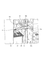
- FIG. 3 is an explanatory diagram showing a case where the longitudinal sectional shape of the inverter device according to the embodiment of the present invention is viewed obliquely from above.
- FIG. 4 is an explanatory diagram showing an enlarged main part in FIG.
- FIG. 5 is an enlarged side view showing the grommet member shown in FIGS. 3 and 4.
- FIG. 6 is an enlarged longitudinal sectional view of the grommet member shown in FIGS. 3 and 4.
- FIG. 7 is an enlarged bottom view of the grommet member shown in FIGS. 3 and 4.
- FIG. 1 to 4 each show an inverter apparatus according to an embodiment of the present invention.
- FIG. 1 is a perspective view
- FIG. 2 is a front view
- FIG. 3 is a case where a longitudinal sectional shape is viewed obliquely from above.
- FIG. 4 is an explanatory diagram showing an enlarged main part in FIG.
- the inverter device 1 exemplified here converts AC power supplied from a commercial power source into AC power having a desired frequency and voltage and outputs the AC power.
- a control chamber 10 a is defined by a front cover 11, a back cover (cover member) 12, a pair of left and right side covers 13, a top plate 14 and a bottom plate 15, while the back cover 12 and the frame 16 defines a heat radiating chamber 10b.
- the control chamber 10 a and the heat radiating chamber 10 b are arranged side by side in a manner adjacent to each other with the back cover 12 interposed therebetween.
- the control room 10a accommodates various control circuit devices, and waterproofness is ensured by applying waterproof processing to the joint portion between the covers.
- the heat radiating chamber 10b accommodates cooling fins 17 and cooling fans 18 that are heat radiating devices for cooling heat-generating components (such as power semiconductor elements) disposed on the control chamber 10a side and cooling the internal atmosphere of the control chamber 10a.
- a direct current reactor (DCR) 19 is accommodated.
- the heat radiation chamber 10b is formed with openings at predetermined locations such as the upper end surface and the lower end surface of the frame 16, and a part thereof is open to the outside.
- a through hole (hole) 12a is formed in the back cover 12 interposed between the control chamber 10a and the heat radiating chamber 10b.
- This through hole 12a is a wiring cable C connected between the control chamber 10a and the heat radiating chamber 10b, more specifically, an output terminal in a predetermined control circuit device of the control chamber 10a and a DC reactor 19 of the heat radiating chamber 10b.
- the wiring cable C for connecting the input terminal and the wiring cable C for connecting the output terminal of the DC reactor 19 and the input terminal in another control circuit device of the control room 10a are laid.
- the grommet member 20 is provided in a manner in which a part thereof is inserted into the through hole 12a.
- FIGS. 3 and 4 are enlarged views of the grommet member shown in FIGS. 3 and 4, respectively.
- FIG. 5 is a side view
- FIG. 6 is a longitudinal sectional view
- FIG. 7 is a bottom view.
- the grommet member 20 exemplified here is formed in a cylindrical shape by a resin material such as rubber, and the wiring cable C connected between the control chamber 10a and the heat radiation chamber 10b passes through the hollow portion 20a. It is arranged by.
- the grommet member 20 includes a base portion 21 and a guide portion 22.
- the base 21 is a substantially cylindrical part. On the outer peripheral surface of the base portion 21, a plurality of projecting pieces 211 projecting outward in the radial direction and extending in the circumferential direction are formed at predetermined intervals along the axial direction of the base portion 21.
- the width of the base portion 21, that is, the width of the portion excluding the projecting piece 211 is slightly larger than the inner diameter of the through hole 12 a. Therefore, by causing the base 21 to enter the through hole 12a from the side of the heat radiating chamber 10b, the base 21 is attached to the through hole 12a while being elastically deformed and penetrates the through hole 12a. become. At this time, the base end of the base portion 21 is mounted so as to face the control chamber 10a, and the projecting piece 211 acts as a restricting piece that restricts the movement of the base portion 21.
- a step 212 is formed between the base end region 21a, that is, the inner surface of the region proximate to the control chamber 10a, and the tip end region 21b. Is formed.
- the guide portion 22 is integrally provided with a resin material having the same quality as the base portion 21 and has a base end portion 221 and a tip end portion 222.
- the base end portion 221 is formed continuously at the tip of the base portion 21, and the central axis coincides with the central axis of the base portion 21 and extends toward the heat radiating chamber 10 b along the front-rear direction (horizontal direction). It is.
- the distal end portion 222 is a portion that is formed continuously with the proximal end portion 221 and curves downward.
- the guide portion 22 has a central axis extending along the front-rear direction at the base end portion 221 in the same manner as the base portion 21, and downward at the tip end portion 222. It is curved.
- the thickness of the guide portion 22 is smaller than the thickness of the base portion 21 and is configured to be softer than the base portion 21.
- the grommet member 20 configured to include the base portion 21 and the guide portion 22 has a slit S formed at the lower portion thereof over the entire length.
- the grommet member 20 in which the base portion 21 is attached to the through hole 12a of the back cover 12 is such that the wiring cable C passes through the hollow portion 20a. It is arranged.
- the guide portion 22 of the grommet member 20 has a base end portion 221 extending from the base portion 21 toward the heat radiating chamber 10b along the front-rear direction and a tip end portion 222 being curved downward. Thereby, even if rainwater enters from the opening formed in the upper end surface of the frame 16 that defines the heat radiation chamber 10b, the rainwater may enter the hollow portion 20a from the opening of the end portion 222 of the grommet member 20.
- control room 10a can ensure a good waterproof property by a simple operation.
- the guide portion 22 of the grommet member 20 has a thickness smaller than that of the base portion 21 and is configured to be softer than the base portion 21. It can be deformed and can follow the laying shape of the wiring cable C.
- the base 21 of the grommet member 20 has a step 212 formed between the inner surface of the base end region 21 a and the tip end region 21 b by protruding inward. Even if water enters the hollow portion 20a of the member 20, the entry of water can be restricted by the step 212, and thus the waterproof property of the control chamber 10a can be more reliably ensured.
- the grommet member 20 can be elastically deformed so as to increase the width of the slit S.
- the grommet member 20 can be elastically deformed so as to increase the width of the slit S.
- the guide portion 22 of the grommet member 20 is formed of the same resin material as the base portion 21 and is configured integrally with the base portion 21.
- the guide portion is the base portion. It may be formed of a different resin material, and may be integrally formed by joining to the base portion thereafter.
- the thickness of the guide portion 22 of the grommet member 20 is softer than the thickness of the base portion 21, but in the present invention, the thickness of the guide portion is approximately the same as the thickness of the base portion. It does not matter if it is softer than the base.
- the step 212 is formed on the base 21 of the grommet member 20, but in the present invention, such a step may not be provided.
- the slit S is formed over the entire length of the lower portion of the grommet member 20, but in the present invention, such a slit may not be formed.
- the wiring cable C connected between the control chamber 10a and the heat radiation chamber 10b is exemplified as being connected to the DC reactor 19, but in the present invention, the wiring cable C is connected to the DC reactor.
- the present invention is not limited thereto, and any device may be used as long as it is a wiring cable connected between the control room and the heat radiating room.
Landscapes
- Engineering & Computer Science (AREA)
- Microelectronics & Electronic Packaging (AREA)
- Power Engineering (AREA)
- Physics & Mathematics (AREA)
- Thermal Sciences (AREA)
- Insertion, Bundling And Securing Of Wires For Electric Apparatuses (AREA)
- Installation Of Indoor Wiring (AREA)
- Casings For Electric Apparatus (AREA)
- Cooling Or The Like Of Electrical Apparatus (AREA)
- Inverter Devices (AREA)
Abstract
各種制御回路機器を収納し、かつ防水性が確保された制御室10aと、制御室10aの内部雰囲気を冷却するための放熱機器を収納し、かつ一部が外部に開放された放熱室10bとが互いに隣接する態様で並設されたインバータ装置1において、制御室10aと放熱室10bとに介在する裏面カバー12の貫通孔12aに一部が挿入された状態で設けられ、かつ制御室10aと放熱室10bとの間で接続される配線ケーブルCが中空部20aを通過する態様で配設される筒状のグロメット部材20を備え、グロメット部材20は、貫通孔12aを貫通した状態で貫通孔12aに装着される基部21と、基端部221が基部21より放熱室10bに向けて延在し、かつ基端部221に連続する先端部222が下方に向けて湾曲するガイド部22とを有して成るものである。
Description
本発明は、インバータ装置に関するものである。
従来、商用の交流電源等から交流電力を受電し、任意の周波数及び電圧の交流電力に変換して出力することにより負荷を駆動するインバータ装置においては、フレームや各カバーを組み合わせることによって各種制御回路機器を主として収納する制御室と、該制御室の内部雰囲気を冷却するための放熱機器を主として収納する放熱室とが設けられており、これらの室は互いに隣接する態様で並設されている。
そして、制御室は、その特性上防水加工が施されており、これにより防水性が確保されている。その一方、放熱室は、外気を取り込む構成を成しており、一部が外部に開放されている。
このようなインバータ装置では、制御室と放熱室とを跨ぐように配線ケーブルを敷設することが求められる場合があるが、このような場合、制御室と放熱室とを区画するカバーに貫通孔を形成し、かかる貫通孔を通過する態様で配線ケーブルを敷設することになる。
しかしながら、このように貫通孔を通過する態様で配線ケーブルを敷設すると、放熱室に進入した雨水等が配線ケーブルを伝って制御室に進入してしまう虞れがある。
そこで、雨水等が制御室に進入してしまうことを防止すべく、貫通孔と配線ケーブルとの隙間に封止樹脂を充填する技術が提案されている(例えば、特許文献1参照)。
ところが、上述した特許文献1に提案の技術では、貫通孔と配線ケーブルとの隙間に封止樹脂を充填させていたので、充填が不十分であると制御室に雨水等が進入してしまう虞れがあり、封止樹脂の充填作業には高い精度が要求されていた。また、配線ケーブルを貫通させた後に封止樹脂を充填するという追加の処理を施すことから作業工数が増えるという問題があった。そのため、良好な防水性を確保するためには製造作業が煩雑なものとなっていた。
本発明は、上記実情に鑑みて、簡単な作業で制御室が良好な防水性を確保することができるインバータ装置を提供することを目的とする。
上記目的を達成するために、本発明は、各種制御回路機器を主として収納し、かつ防水性が確保された制御室と、前記制御室の内部雰囲気を冷却するための放熱機器を主として収納し、かつ一部が外部に開放された放熱室とが互いに隣接する態様で並設されたインバータ装置に関するものである。本発明に係るインバータ装置は、前記制御室と前記放熱室とに介在するカバー部材に形成された孔部に一部が挿入された状態で設けられ、かつ前記制御室と前記放熱室との間で接続される配線ケーブルが自身の中空部を通過する態様で配設される筒状のグロメット部材を備えている。このグロメット部材は、前記孔部を貫通した状態で該孔部に装着される基部と、基端部が前記基部より前記放熱室に向けて延在し、かつ前記基端部に連続する先端部が下方に向けて湾曲するガイド部とを有して成るものである。
また、本発明は、上記インバータ装置において、前記ガイド部は、前記基部と同一の樹脂材により形成されて該基部と一体に構成されており、厚みが前記基部の厚みよりも小さくて軟質である。
また、本発明は、上記インバータ装置において、前記基部は、前記制御室に近接する領域の内面が内方に突出することで段差が形成されて成るものである。
また、本発明は、上記インバータ装置において、前記グロメット部材は、下部において全長に亘ってスリットが形成されて成るものである。
本発明によれば、制御室と放熱室とに介在するカバー部材に形成された孔部に基部が装着された筒状のグロメット部材は、制御室と放熱室との間で接続される配線ケーブルが中空部を通過する態様で配設されている。そしてグロメット部材のガイド部は、基端部が基部より放熱室に向けて延在し、かつ基端部に連続する先端部が下方に向けて湾曲している。これにより、外部より放熱室に雨水が進入したとしても、その雨水がグロメット部材の先端部の開口より中空部に進入する虞れがなく、また配線ケーブルを伝ってグロメット部材の内部にまで進入する虞れもない。これにより制御室の防水性を十分に確保することができる。しかも、従来のように封止樹脂を充填させるような作業は不要で、グロメット部材の中空部を配線ケーブルが通過するようにした後に該グロメット部材の基部を孔部に押圧した状態で進入させればよいので、取付作業も簡単なものである。従って、簡単な作業で制御室が良好な防水性を確保することができるという効果を奏する。
以下に添付図面を参照して、本発明に係るインバータ装置の好適な実施の形態について詳細に説明する。
図1~図4は、それぞれ本発明の実施の形態であるインバータ装置を示すものであり、図1は斜視図、図2は正面図、図3は縦断面形状を斜め上方から見た場合を示す説明図、図4は図3における要部を拡大して示す説明図である。ここで例示するインバータ装置1は、商用電源から供給された交流電力を所望の周波数及び電圧の交流電力に変換して出力するものである。
上記インバータ装置1においては、表面カバー11、裏面カバー(カバー部材)12、左右一対のサイドカバー13、天板14及び底板15により制御室10aが画成されている一方、上記裏面カバー12とフレーム16とにより放熱室10bが画成されている。このようにインバータ装置1では、制御室10aと放熱室10bとが裏面カバー12を介在して互いに前後に隣接する態様で並設されている。
制御室10aは、各種制御回路機器を収納してあり、カバー同士の接合部位に防水加工が施されることにより防水性が確保されている。
放熱室10bは、制御室10a側に配置した発熱部品(パワー半導体素子等)の冷却や制御室10aの内部雰囲気を冷却するための放熱機器である冷却フィン17や冷却ファン18が収納されているとともに、直流リアクトル(DCR)19が収納されている。この放熱室10bは、フレーム16の上端面や下端面等の所定個所に開口が形成されており、一部が外部に開放されている。
このような制御室10aと放熱室10bとの間に介在する裏面カバー12には貫通孔(孔部)12aが形成されている。この貫通孔12aは、制御室10aと放熱室10bとの間で接続される配線ケーブルC、より詳細には、制御室10aの所定の制御回路機器における出力端子と放熱室10bの直流リアクトル19の入力端子とを接続する配線ケーブルC、並びに直流リアクトル19の出力端子と制御室10aの他の制御回路機器における入力端子とを接続する配線ケーブルCを敷設させるためのものである。
本実施の形態であるインバータ装置1においては、上記貫通孔12aに一部が挿入された態様でグロメット部材20が設けられている。
図5~図7は、それぞれ図3及び図4に示したグロメット部材を拡大して示すものであり、図5は側面図、図6は縦断面図、図7は底面図である。
ここで例示するグロメット部材20は、ゴム等の樹脂材により筒状に形成されたものであり、制御室10aと放熱室10bとの間で接続される配線ケーブルCが中空部20aを通過する態様で配設されている。このグロメット部材20は、基部21とガイド部22とを備えて構成されている。
基部21は、略円筒状を成す部位である。この基部21の外周面には、径外方向に向けて突出し、かつ周方向に亘って延在する複数の突片211が該基部21の軸方向に沿って所定間隔毎に形成されている。このような基部21の幅、すなわち突片211を除く部分の幅は、上記貫通孔12aの内径よりも僅かに大きいものである。従って、かかる基部21を放熱室10b側から貫通孔12aに押圧した状態で進入させることで、該基部21は弾性変形しつつ該貫通孔12aを貫通した状態で該貫通孔12aに装着されることになる。このとき、基部21の基端が制御室10aを臨むように装着されており、突片211が基部21の移動を規制する規制片として作用する。
このような基部21においては、図6に示すように、基端側領域21a、すなわち制御室10aに近接する領域の内面が内方に突出することで先端側領域21bとの間で段差212が形成されている。
ガイド部22は、前記基部21と同質の樹脂材にて一体的に設けられており、基端部221と先端部222とを有している。基端部221は、基部21の先端に連続して形成されており、中心軸が基部21の中心軸に一致して前後方向(水平方向)に沿って放熱室10bに向けて延在する部位である。先端部222は、基端部221に連続して形成されており、下方に向けて湾曲する部位である。
このようにガイド部22は、図5に示すように、その中心軸が基端部221では上記基部21と同様に前後方向に沿って延在しており、先端部222においては下方に向けて湾曲している。
また、ガイド部22は、図6に示すように、その厚みが基部21の厚みよりも小さくなっており、該基部21よりも軟質に構成されている。
これら基部21及びガイド部22を備えて構成されるグロメット部材20は、図7に示すように、その下部において全長に亘ってスリットSが形成されている。
以上のような構成を有する本実施の形態であるインバータ装置1においては、裏面カバー12の貫通孔12aに基部21が装着されたグロメット部材20は、配線ケーブルCが中空部20aを通過する態様で配設されている。そしてグロメット部材20のガイド部22は、基端部221が基部21より放熱室10bに向けて前後方向に沿って延在しつつ先端部222が下方に向けて湾曲している。これにより、放熱室10bを画成するフレーム16の上端面等に形成された開口より雨水が進入したとしても、その雨水がグロメット部材20の先端部222の開口より中空部20aに進入する虞れがなく、また配線ケーブルCを伝ってグロメット部材20の内部にまで進入する虞れもない。これにより制御室10aの防水性を十分に確保することができる。しかも、従来のように封止樹脂を充填させるような作業は不要で、グロメット部材20の中空部20aを配線ケーブルCが通過するようにした後に該グロメット部材20の基部21を貫通孔12aに押圧した状態で進入させればよいので、取付作業も簡単なものである。
従って、本発明の実施の形態であるインバータ装置1によれば、簡単な作業で制御室10aが良好な防水性を確保することができる。
上記インバータ装置1においては、グロメット部材20のガイド部22は、その厚みが基部21の厚みよりも小さくなっており該基部21よりも軟質に構成されているので、ガイド部22の形状を容易に変形させることができ、配線ケーブルCの敷設形状に追従させることができる。
上記インバータ装置1においては、グロメット部材20の基部21には、基端側領域21aの内面が内方に突出することで先端側領域21bとの間で段差212が形成されているので、仮にグロメット部材20の中空部20aに水が進入したとしても、かかる段差212で水の進入を規制することができ、これにより、制御室10aの防水性をより確実に確保することができる。
上記インバータ装置1においては、グロメット部材20の下部の全長に亘ってスリットSが形成されているので、かかるスリットSの幅を拡大させるようにグロメット部材20を弾性変形させることができる。このようにグロメット部材20を弾性変形させることで、配線ケーブルCが複数本ある場合でも中空部20aに配線ケーブルCを1本1本通過させることなく、スリットSを介して既に敷設されている複数本の配線ケーブルCを中空部20aに一括して進入させることができる。これにより、取付作業の簡易化を図ることができる。
以上、本発明の好適な実施の形態について説明したが、本発明はこれに限定されるものではなく、種々の変更を行うことができる。
上述した実施の形態では、グロメット部材20のガイド部22は、基部21と同一の樹脂材により形成されて該基部21と一体に構成されていたが、本発明においては、ガイド部は、基部と異なる樹脂材により形成されていても良く、その後に基部と接合されて一体的に構成されていても良い。
上述した実施の形態では、グロメット部材20のガイド部22の厚みが基部21の厚みよりも小さくて軟質であったが、本発明においては、ガイド部の厚みが基部の厚みと同程度であっても良く、また基部よりも軟質でなくても構わない。
上述した実施の形態では、グロメット部材20の基部21に段差212が形成されていたが、本発明においては、かかる段差が設けられていなくても構わない。
上述した実施の形態では、グロメット部材20の下部の全長に亘ってスリットSが形成されていたが、本発明においては、かかるスリットが形成されていなくても良い。
上述した実施の形態では、制御室10aと放熱室10bとの間に接続される配線ケーブルCとして直流リアクトル19に接続されるものを例示したが、本発明においては、直流リアクトルに接続されるものに限定されず、制御室と放熱室との間で接続される配線ケーブルであればどのような機器に接続されるものであっても構わない。
1 インバータ装置
10a 制御室
10b 放熱室
11 表面カバー
12 裏面カバー(カバー部材)
12a 貫通孔(孔部)
13 サイドカバー
14 天板
15 底板
16 フレーム
17 冷却フィン
18 冷却ファン
19 直流リアクトル
20 グロメット部材
20a 中空部
21 基部
21a 基端側領域
21b 先端側領域
211 突片
212 段差
22 ガイド部
221 基端部
222 先端部
C 配線ケーブル
S スリット
10a 制御室
10b 放熱室
11 表面カバー
12 裏面カバー(カバー部材)
12a 貫通孔(孔部)
13 サイドカバー
14 天板
15 底板
16 フレーム
17 冷却フィン
18 冷却ファン
19 直流リアクトル
20 グロメット部材
20a 中空部
21 基部
21a 基端側領域
21b 先端側領域
211 突片
212 段差
22 ガイド部
221 基端部
222 先端部
C 配線ケーブル
S スリット
Claims (4)
- 各種制御回路機器を主として収納し、かつ防水性が確保された制御室と、前記制御室の内部雰囲気を冷却するための放熱機器を主として収納し、かつ一部が外部に開放された放熱室とが互いに隣接する態様で並設されたインバータ装置において、
前記制御室と前記放熱室とに介在するカバー部材に形成された孔部に一部が挿入された状態で設けられ、かつ前記制御室と前記放熱室との間で接続される配線ケーブルが自身の中空部を通過する態様で配設される筒状のグロメット部材を備え、
前記グロメット部材は、
前記孔部を貫通した状態で該孔部に装着される基部と、
基端部が前記基部より前記放熱室に向けて延在し、かつ前記基端部に連続する先端部が下方に向けて湾曲するガイド部と
を有して成ることを特徴とするインバータ装置。 - 前記ガイド部は、前記基部と同一の樹脂材により形成されて該基部と一体に構成されており、厚みが前記基部の厚みよりも小さくて軟質であることを特徴とする請求項1に記載のインバータ装置。
- 前記基部は、前記制御室に近接する領域の内面が内方に突出することで段差が形成されて成ることを特徴とする請求項1又は請求項2に記載のインバータ装置。
- 前記グロメット部材は、下部において全長に亘ってスリットが形成されて成ることを特徴とする請求項1~3のいずれか1つに記載のインバータ装置。
Priority Applications (2)
| Application Number | Priority Date | Filing Date | Title |
|---|---|---|---|
| EP13820027.4A EP2876802B1 (en) | 2012-07-20 | 2013-05-30 | Inverter device |
| CN201380019189.2A CN104205606B (zh) | 2012-07-20 | 2013-05-30 | 逆变器装置 |
Applications Claiming Priority (2)
| Application Number | Priority Date | Filing Date | Title |
|---|---|---|---|
| JP2012161862A JP5915431B2 (ja) | 2012-07-20 | 2012-07-20 | インバータ装置 |
| JP2012-161862 | 2012-07-20 |
Publications (1)
| Publication Number | Publication Date |
|---|---|
| WO2014013799A1 true WO2014013799A1 (ja) | 2014-01-23 |
Family
ID=49948635
Family Applications (1)
| Application Number | Title | Priority Date | Filing Date |
|---|---|---|---|
| PCT/JP2013/065042 Ceased WO2014013799A1 (ja) | 2012-07-20 | 2013-05-30 | インバータ装置 |
Country Status (4)
| Country | Link |
|---|---|
| EP (1) | EP2876802B1 (ja) |
| JP (1) | JP5915431B2 (ja) |
| CN (1) | CN104205606B (ja) |
| WO (1) | WO2014013799A1 (ja) |
Families Citing this family (1)
| Publication number | Priority date | Publication date | Assignee | Title |
|---|---|---|---|---|
| JP7324736B2 (ja) * | 2020-07-02 | 2023-08-10 | 日立グローバルライフソリューションズ株式会社 | 冷蔵庫 |
Citations (5)
| Publication number | Priority date | Publication date | Assignee | Title |
|---|---|---|---|---|
| JPH0168627U (ja) * | 1987-10-28 | 1989-05-02 | ||
| JPH09275676A (ja) * | 1996-04-01 | 1997-10-21 | Nissan Motor Co Ltd | Dc−dcコンバータ |
| JP2000195685A (ja) * | 1998-12-24 | 2000-07-14 | Denso Corp | 放電灯点灯装置 |
| JP2005019791A (ja) | 2003-06-27 | 2005-01-20 | Matsushita Electric Ind Co Ltd | パワー制御装置 |
| JP2005348534A (ja) * | 2004-06-03 | 2005-12-15 | Fuji Electric Fa Components & Systems Co Ltd | インバータ装置 |
Family Cites Families (15)
| Publication number | Priority date | Publication date | Assignee | Title |
|---|---|---|---|---|
| US4394706A (en) * | 1979-07-11 | 1983-07-19 | Progressive Dynamics, Inc. | Power converter for recreational vehicles |
| DE3721901A1 (de) * | 1987-07-02 | 1989-01-12 | Heidelberger Druckmasch Ag | Schaltschrank |
| KR920005988B1 (ko) * | 1988-08-31 | 1992-07-25 | 가부시기가이샤 히다찌세이사꾸쇼 | 인버터장치 |
| JP2000195686A (ja) * | 1998-12-24 | 2000-07-14 | Matsushita Electric Works Ltd | 非常用照明装置 |
| JP2002095109A (ja) * | 2000-09-08 | 2002-03-29 | Toshiba Transport Eng Inc | 車両用高周波方式電源装置 |
| JP2003004170A (ja) * | 2001-06-20 | 2003-01-08 | Furukawa Electric Co Ltd:The | ケーブル貫通部用グロメット |
| US7154755B2 (en) * | 2004-04-12 | 2006-12-26 | Richard Alberto Araujo | Power supply assembly |
| ES2377018T3 (es) * | 2004-06-24 | 2012-03-21 | Sma Solar Technology Ag | Inversor con una carcasa con componentes eléctricos y/o electrónicos presentando disipadores de calor |
| JP4848187B2 (ja) * | 2006-01-17 | 2011-12-28 | 日立オートモティブシステムズ株式会社 | 電力変換装置 |
| WO2007098617A1 (de) * | 2006-02-28 | 2007-09-07 | Huber+Suhner Ag | Abgewinkelter steckverbinder für koaxialkabel |
| JP5109965B2 (ja) * | 2008-12-24 | 2012-12-26 | 住友電装株式会社 | グロメット |
| CN201409083Y (zh) * | 2009-05-22 | 2010-02-17 | 合肥阳光电源有限公司 | 一种逆变器箱体散热防水结构 |
| JP5644434B2 (ja) * | 2010-12-02 | 2014-12-24 | 富士電機株式会社 | 電力変換装置及びこれを使用した電気駆動車両 |
| JP2012228018A (ja) * | 2011-04-18 | 2012-11-15 | Yaskawa Electric Corp | 電力変換装置 |
| JP5510750B2 (ja) * | 2011-04-18 | 2014-06-04 | 株式会社安川電機 | 電力変換装置及びリアクトル |
-
2012
- 2012-07-20 JP JP2012161862A patent/JP5915431B2/ja not_active Expired - Fee Related
-
2013
- 2013-05-30 EP EP13820027.4A patent/EP2876802B1/en not_active Not-in-force
- 2013-05-30 CN CN201380019189.2A patent/CN104205606B/zh not_active Expired - Fee Related
- 2013-05-30 WO PCT/JP2013/065042 patent/WO2014013799A1/ja not_active Ceased
Patent Citations (5)
| Publication number | Priority date | Publication date | Assignee | Title |
|---|---|---|---|---|
| JPH0168627U (ja) * | 1987-10-28 | 1989-05-02 | ||
| JPH09275676A (ja) * | 1996-04-01 | 1997-10-21 | Nissan Motor Co Ltd | Dc−dcコンバータ |
| JP2000195685A (ja) * | 1998-12-24 | 2000-07-14 | Denso Corp | 放電灯点灯装置 |
| JP2005019791A (ja) | 2003-06-27 | 2005-01-20 | Matsushita Electric Ind Co Ltd | パワー制御装置 |
| JP2005348534A (ja) * | 2004-06-03 | 2005-12-15 | Fuji Electric Fa Components & Systems Co Ltd | インバータ装置 |
Non-Patent Citations (1)
| Title |
|---|
| See also references of EP2876802A4 |
Also Published As
| Publication number | Publication date |
|---|---|
| JP2014023356A (ja) | 2014-02-03 |
| EP2876802B1 (en) | 2017-08-30 |
| JP5915431B2 (ja) | 2016-05-11 |
| EP2876802A4 (en) | 2016-04-06 |
| CN104205606A (zh) | 2014-12-10 |
| CN104205606B (zh) | 2018-02-23 |
| EP2876802A1 (en) | 2015-05-27 |
Similar Documents
| Publication | Publication Date | Title |
|---|---|---|
| JP5510750B2 (ja) | 電力変換装置及びリアクトル | |
| JP5454800B2 (ja) | 電力変換装置及びそのコンデンサカバー | |
| JP2012228018A (ja) | 電力変換装置 | |
| US10658939B2 (en) | Power conversion apparatus and noise filter | |
| US9929669B2 (en) | Inverter | |
| CN103887746B (zh) | 电气接线盒 | |
| EP2584664A4 (en) | CABLE TREE WITH INTEGRATED SHADE | |
| WO2020153647A8 (ko) | 감열선을 내장한 복합 전력 케이블 및 이를 구비한 과열 보호 장치 | |
| JP2017099205A (ja) | 電線外装材およびワイヤハーネス | |
| CN107578841A (zh) | 屏蔽线束 | |
| US9331463B2 (en) | Wire fixture | |
| JP2014026938A (ja) | 照明装置 | |
| JP5915431B2 (ja) | インバータ装置 | |
| KR102166558B1 (ko) | 선형 부재의 방수 처리 구조 | |
| JP6181964B2 (ja) | 照明器具 | |
| JP6319123B2 (ja) | 配線引き込み構造 | |
| JP2012038673A (ja) | ワイヤハーネス | |
| JP6146364B2 (ja) | 電力変換装置 | |
| KR101810425B1 (ko) | 엘이디 조명장치 | |
| JP2015156752A (ja) | 電気接続箱 | |
| JP6210971B2 (ja) | 止水構造及びワイヤハーネス | |
| US9331541B2 (en) | Motor structure | |
| KR200478835Y1 (ko) | 이중 고정 그로멧 | |
| JP2008028339A (ja) | 電気機器ケース | |
| JP2002158320A (ja) | 電源装置のヒートシンク構造及びヒートシンク |
Legal Events
| Date | Code | Title | Description |
|---|---|---|---|
| 121 | Ep: the epo has been informed by wipo that ep was designated in this application |
Ref document number: 13820027 Country of ref document: EP Kind code of ref document: A1 |
|
| REEP | Request for entry into the european phase |
Ref document number: 2013820027 Country of ref document: EP |
|
| WWE | Wipo information: entry into national phase |
Ref document number: 2013820027 Country of ref document: EP |
|
| NENP | Non-entry into the national phase |
Ref country code: DE |