WO2014013799A1 - Dispositif onduleur - Google Patents
Dispositif onduleur Download PDFInfo
- Publication number
- WO2014013799A1 WO2014013799A1 PCT/JP2013/065042 JP2013065042W WO2014013799A1 WO 2014013799 A1 WO2014013799 A1 WO 2014013799A1 JP 2013065042 W JP2013065042 W JP 2013065042W WO 2014013799 A1 WO2014013799 A1 WO 2014013799A1
- Authority
- WO
- WIPO (PCT)
- Prior art keywords
- chamber
- base
- inverter device
- heat dissipation
- grommet member
- Prior art date
- Legal status (The legal status is an assumption and is not a legal conclusion. Google has not performed a legal analysis and makes no representation as to the accuracy of the status listed.)
- Ceased
Links
Images


Classifications
-
- H—ELECTRICITY
- H02—GENERATION; CONVERSION OR DISTRIBUTION OF ELECTRIC POWER
- H02M—APPARATUS FOR CONVERSION BETWEEN AC AND AC, BETWEEN AC AND DC, OR BETWEEN DC AND DC, AND FOR USE WITH MAINS OR SIMILAR POWER SUPPLY SYSTEMS; CONVERSION OF DC OR AC INPUT POWER INTO SURGE OUTPUT POWER; CONTROL OR REGULATION THEREOF
- H02M7/00—Conversion of AC power input into DC power output; Conversion of DC power input into AC power output
- H02M7/003—Constructional details, e.g. physical layout, assembly, wiring or busbar connections
-
- H—ELECTRICITY
- H05—ELECTRIC TECHNIQUES NOT OTHERWISE PROVIDED FOR
- H05K—PRINTED CIRCUITS; CASINGS OR CONSTRUCTIONAL DETAILS OF ELECTRIC APPARATUS; MANUFACTURE OF ASSEMBLAGES OF ELECTRICAL COMPONENTS
- H05K7/00—Constructional details common to different types of electric apparatus
- H05K7/14—Mounting supporting structure in casing or on frame or rack
- H05K7/1422—Printed circuit boards receptacles, e.g. stacked structures, electronic circuit modules or box like frames
- H05K7/1427—Housings
- H05K7/1432—Housings specially adapted for power drive units or power converters
- H05K7/14322—Housings specially adapted for power drive units or power converters wherein the control and power circuits of a power converter are arranged within the same casing
-
- H—ELECTRICITY
- H05—ELECTRIC TECHNIQUES NOT OTHERWISE PROVIDED FOR
- H05K—PRINTED CIRCUITS; CASINGS OR CONSTRUCTIONAL DETAILS OF ELECTRIC APPARATUS; MANUFACTURE OF ASSEMBLAGES OF ELECTRICAL COMPONENTS
- H05K7/00—Constructional details common to different types of electric apparatus
- H05K7/20—Modifications to facilitate cooling, ventilating, or heating
- H05K7/2089—Modifications to facilitate cooling, ventilating, or heating for power electronics, e.g. for inverters for controlling motor
- H05K7/20909—Forced ventilation, e.g. on heat dissipaters coupled to components
- H05K7/20918—Forced ventilation, e.g. on heat dissipaters coupled to components the components being isolated from air flow, e.g. hollow heat sinks, wind tunnels or funnels
Definitions
- the present invention relates to an inverter device.
- control circuits are combined by combining a frame and each cover.
- a control chamber that mainly stores equipment and a heat radiating chamber that mainly stores heat radiating equipment for cooling the internal atmosphere of the control room are provided, and these chambers are arranged side by side so as to be adjacent to each other.
- the control room is waterproofed due to its characteristics, which ensures waterproofness.
- the heat radiation chamber is configured to take in outside air, and a part thereof is open to the outside.
- inverter device it may be required to lay a wiring cable so as to straddle the control room and the heat radiating room.
- a through hole is provided in the cover that divides the control room and the heat radiating room.
- the wiring cable is laid in such a manner that it is formed and passes through the through hole.
- an object of the present invention is to provide an inverter device in which a control room can ensure a good waterproof property with a simple operation.
- the present invention mainly stores various control circuit devices and a control room in which waterproofness is ensured, and a heat dissipation device for cooling the internal atmosphere of the control room.
- the present invention relates to an inverter device that is arranged side by side in a manner in which a part of the heat radiation chamber that is open to the outside is adjacent to each other.
- the inverter device according to the present invention is provided in a state where a part is inserted in a hole formed in a cover member interposed between the control chamber and the heat radiation chamber, and between the control chamber and the heat radiation chamber.
- the tubular cable grommet member is provided in such a manner that the wiring cable connected in step 1 passes through its own hollow portion.
- the grommet member includes a base portion that is attached to the hole portion in a state of penetrating the hole portion, and a distal end portion that has a proximal end portion extending from the base portion toward the heat radiating chamber and is continuous with the proximal end portion. Has a guide part that curves downward.
- the guide part is formed of the same resin material as the base part and is integrally formed with the base part, and the thickness is smaller than the thickness of the base part and is soft. .
- the base portion is formed with a step by projecting inwardly an inner surface of a region close to the control chamber.
- the grommet member has a slit formed in the lower part over the entire length.
- the tubular grommet member having the base portion mounted in the hole formed in the cover member interposed between the control chamber and the heat radiating chamber is connected to the control cable and the heat radiating chamber. Is disposed in a manner that passes through the hollow portion.
- the guide portion of the grommet member has a base end portion extending from the base portion toward the heat radiating chamber, and a distal end portion continuing to the base end portion is curved downward.
- the waterproofness of the control room can be sufficiently secured.
- the work of filling the sealing resin as in the prior art is unnecessary, and after the wiring cable passes through the hollow part of the grommet member, the base part of the grommet member is pushed into the hole and can be entered. Since it is sufficient, the installation work is also simple. Therefore, there is an effect that the control room can secure a good waterproof property by a simple operation.
- FIG. 1 is a perspective view showing an inverter device according to an embodiment of the present invention.
- FIG. 2 is a front view showing the inverter device according to the embodiment of the present invention.
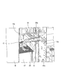
- FIG. 3 is an explanatory diagram showing a case where the longitudinal sectional shape of the inverter device according to the embodiment of the present invention is viewed obliquely from above.
- FIG. 4 is an explanatory diagram showing an enlarged main part in FIG.
- FIG. 5 is an enlarged side view showing the grommet member shown in FIGS. 3 and 4.
- FIG. 6 is an enlarged longitudinal sectional view of the grommet member shown in FIGS. 3 and 4.
- FIG. 7 is an enlarged bottom view of the grommet member shown in FIGS. 3 and 4.
- FIG. 1 to 4 each show an inverter apparatus according to an embodiment of the present invention.
- FIG. 1 is a perspective view
- FIG. 2 is a front view
- FIG. 3 is a case where a longitudinal sectional shape is viewed obliquely from above.
- FIG. 4 is an explanatory diagram showing an enlarged main part in FIG.
- the inverter device 1 exemplified here converts AC power supplied from a commercial power source into AC power having a desired frequency and voltage and outputs the AC power.
- a control chamber 10 a is defined by a front cover 11, a back cover (cover member) 12, a pair of left and right side covers 13, a top plate 14 and a bottom plate 15, while the back cover 12 and the frame 16 defines a heat radiating chamber 10b.
- the control chamber 10 a and the heat radiating chamber 10 b are arranged side by side in a manner adjacent to each other with the back cover 12 interposed therebetween.
- the control room 10a accommodates various control circuit devices, and waterproofness is ensured by applying waterproof processing to the joint portion between the covers.
- the heat radiating chamber 10b accommodates cooling fins 17 and cooling fans 18 that are heat radiating devices for cooling heat-generating components (such as power semiconductor elements) disposed on the control chamber 10a side and cooling the internal atmosphere of the control chamber 10a.
- a direct current reactor (DCR) 19 is accommodated.
- the heat radiation chamber 10b is formed with openings at predetermined locations such as the upper end surface and the lower end surface of the frame 16, and a part thereof is open to the outside.
- a through hole (hole) 12a is formed in the back cover 12 interposed between the control chamber 10a and the heat radiating chamber 10b.
- This through hole 12a is a wiring cable C connected between the control chamber 10a and the heat radiating chamber 10b, more specifically, an output terminal in a predetermined control circuit device of the control chamber 10a and a DC reactor 19 of the heat radiating chamber 10b.
- the wiring cable C for connecting the input terminal and the wiring cable C for connecting the output terminal of the DC reactor 19 and the input terminal in another control circuit device of the control room 10a are laid.
- the grommet member 20 is provided in a manner in which a part thereof is inserted into the through hole 12a.
- FIGS. 3 and 4 are enlarged views of the grommet member shown in FIGS. 3 and 4, respectively.
- FIG. 5 is a side view
- FIG. 6 is a longitudinal sectional view
- FIG. 7 is a bottom view.
- the grommet member 20 exemplified here is formed in a cylindrical shape by a resin material such as rubber, and the wiring cable C connected between the control chamber 10a and the heat radiation chamber 10b passes through the hollow portion 20a. It is arranged by.
- the grommet member 20 includes a base portion 21 and a guide portion 22.
- the base 21 is a substantially cylindrical part. On the outer peripheral surface of the base portion 21, a plurality of projecting pieces 211 projecting outward in the radial direction and extending in the circumferential direction are formed at predetermined intervals along the axial direction of the base portion 21.
- the width of the base portion 21, that is, the width of the portion excluding the projecting piece 211 is slightly larger than the inner diameter of the through hole 12 a. Therefore, by causing the base 21 to enter the through hole 12a from the side of the heat radiating chamber 10b, the base 21 is attached to the through hole 12a while being elastically deformed and penetrates the through hole 12a. become. At this time, the base end of the base portion 21 is mounted so as to face the control chamber 10a, and the projecting piece 211 acts as a restricting piece that restricts the movement of the base portion 21.
- a step 212 is formed between the base end region 21a, that is, the inner surface of the region proximate to the control chamber 10a, and the tip end region 21b. Is formed.
- the guide portion 22 is integrally provided with a resin material having the same quality as the base portion 21 and has a base end portion 221 and a tip end portion 222.
- the base end portion 221 is formed continuously at the tip of the base portion 21, and the central axis coincides with the central axis of the base portion 21 and extends toward the heat radiating chamber 10 b along the front-rear direction (horizontal direction). It is.
- the distal end portion 222 is a portion that is formed continuously with the proximal end portion 221 and curves downward.
- the guide portion 22 has a central axis extending along the front-rear direction at the base end portion 221 in the same manner as the base portion 21, and downward at the tip end portion 222. It is curved.
- the thickness of the guide portion 22 is smaller than the thickness of the base portion 21 and is configured to be softer than the base portion 21.
- the grommet member 20 configured to include the base portion 21 and the guide portion 22 has a slit S formed at the lower portion thereof over the entire length.
- the grommet member 20 in which the base portion 21 is attached to the through hole 12a of the back cover 12 is such that the wiring cable C passes through the hollow portion 20a. It is arranged.
- the guide portion 22 of the grommet member 20 has a base end portion 221 extending from the base portion 21 toward the heat radiating chamber 10b along the front-rear direction and a tip end portion 222 being curved downward. Thereby, even if rainwater enters from the opening formed in the upper end surface of the frame 16 that defines the heat radiation chamber 10b, the rainwater may enter the hollow portion 20a from the opening of the end portion 222 of the grommet member 20.
- control room 10a can ensure a good waterproof property by a simple operation.
- the guide portion 22 of the grommet member 20 has a thickness smaller than that of the base portion 21 and is configured to be softer than the base portion 21. It can be deformed and can follow the laying shape of the wiring cable C.
- the base 21 of the grommet member 20 has a step 212 formed between the inner surface of the base end region 21 a and the tip end region 21 b by protruding inward. Even if water enters the hollow portion 20a of the member 20, the entry of water can be restricted by the step 212, and thus the waterproof property of the control chamber 10a can be more reliably ensured.
- the grommet member 20 can be elastically deformed so as to increase the width of the slit S.
- the grommet member 20 can be elastically deformed so as to increase the width of the slit S.
- the guide portion 22 of the grommet member 20 is formed of the same resin material as the base portion 21 and is configured integrally with the base portion 21.
- the guide portion is the base portion. It may be formed of a different resin material, and may be integrally formed by joining to the base portion thereafter.
- the thickness of the guide portion 22 of the grommet member 20 is softer than the thickness of the base portion 21, but in the present invention, the thickness of the guide portion is approximately the same as the thickness of the base portion. It does not matter if it is softer than the base.
- the step 212 is formed on the base 21 of the grommet member 20, but in the present invention, such a step may not be provided.
- the slit S is formed over the entire length of the lower portion of the grommet member 20, but in the present invention, such a slit may not be formed.
- the wiring cable C connected between the control chamber 10a and the heat radiation chamber 10b is exemplified as being connected to the DC reactor 19, but in the present invention, the wiring cable C is connected to the DC reactor.
- the present invention is not limited thereto, and any device may be used as long as it is a wiring cable connected between the control room and the heat radiating room.
Landscapes
- Engineering & Computer Science (AREA)
- Microelectronics & Electronic Packaging (AREA)
- Power Engineering (AREA)
- Physics & Mathematics (AREA)
- Thermal Sciences (AREA)
- Insertion, Bundling And Securing Of Wires For Electric Apparatuses (AREA)
- Installation Of Indoor Wiring (AREA)
- Casings For Electric Apparatus (AREA)
- Cooling Or The Like Of Electrical Apparatus (AREA)
- Inverter Devices (AREA)
Abstract
L'invention concerne un dispositif onduleur (1) comprenant : une chambre de commande (10a) et une chambre de dissipation de chaleur (10b) disposées adjacentes l'une à l'autre, la chambre de commande (10a) renfermant des types variés de dispositifs de circuit de commande tout en garantissant une étanchéité, et la chambre de dissipation de chaleur (10b) renfermant un dispositif de dissipation de chaleur pour refroidir l'atmosphère interne de la chambre de commande (10a) tandis qu'une partie de la chambre de dissipation de chaleur (10b) est ouverte sur l'extérieur. Le dispositif inverseur (1) comprend un élément de passe-câbles cylindrique (20) dont une partie est introduite dans un trou traversant (12a) d'un couvercle de surface arrière (12) interposé entre la chambre de commande (10a) et la chambre de dissipation de chaleur, (10b) un câble métallique (C) connecté entre la chambre de commande (10a) et la chambre de dissipation de chaleur (10b) traversant sa partie creuse (20a). L'élément de passe-câbles (20) est constitué d'une partie base (21) qui le traverse et est fixée au trou traversant (12a), et d'une partie de guidage (22), une partie d'extrémité de base (221) s'étendant de la partie base (21) à la chambre de dissipation de chaleur (10b) et une partie pointe (222) qui se prolonge vers la partie d'extrémité de base (221) est incurvée vers le bas.
Priority Applications (2)
| Application Number | Priority Date | Filing Date | Title |
|---|---|---|---|
| EP13820027.4A EP2876802B1 (fr) | 2012-07-20 | 2013-05-30 | Dispositif onduleur |
| CN201380019189.2A CN104205606B (zh) | 2012-07-20 | 2013-05-30 | 逆变器装置 |
Applications Claiming Priority (2)
| Application Number | Priority Date | Filing Date | Title |
|---|---|---|---|
| JP2012161862A JP5915431B2 (ja) | 2012-07-20 | 2012-07-20 | インバータ装置 |
| JP2012-161862 | 2012-07-20 |
Publications (1)
| Publication Number | Publication Date |
|---|---|
| WO2014013799A1 true WO2014013799A1 (fr) | 2014-01-23 |
Family
ID=49948635
Family Applications (1)
| Application Number | Title | Priority Date | Filing Date |
|---|---|---|---|
| PCT/JP2013/065042 Ceased WO2014013799A1 (fr) | 2012-07-20 | 2013-05-30 | Dispositif onduleur |
Country Status (4)
| Country | Link |
|---|---|
| EP (1) | EP2876802B1 (fr) |
| JP (1) | JP5915431B2 (fr) |
| CN (1) | CN104205606B (fr) |
| WO (1) | WO2014013799A1 (fr) |
Families Citing this family (1)
| Publication number | Priority date | Publication date | Assignee | Title |
|---|---|---|---|---|
| JP7324736B2 (ja) * | 2020-07-02 | 2023-08-10 | 日立グローバルライフソリューションズ株式会社 | 冷蔵庫 |
Citations (5)
| Publication number | Priority date | Publication date | Assignee | Title |
|---|---|---|---|---|
| JPH0168627U (fr) * | 1987-10-28 | 1989-05-02 | ||
| JPH09275676A (ja) * | 1996-04-01 | 1997-10-21 | Nissan Motor Co Ltd | Dc−dcコンバータ |
| JP2000195685A (ja) * | 1998-12-24 | 2000-07-14 | Denso Corp | 放電灯点灯装置 |
| JP2005019791A (ja) | 2003-06-27 | 2005-01-20 | Matsushita Electric Ind Co Ltd | パワー制御装置 |
| JP2005348534A (ja) * | 2004-06-03 | 2005-12-15 | Fuji Electric Fa Components & Systems Co Ltd | インバータ装置 |
Family Cites Families (15)
| Publication number | Priority date | Publication date | Assignee | Title |
|---|---|---|---|---|
| US4394706A (en) * | 1979-07-11 | 1983-07-19 | Progressive Dynamics, Inc. | Power converter for recreational vehicles |
| DE3721901A1 (de) * | 1987-07-02 | 1989-01-12 | Heidelberger Druckmasch Ag | Schaltschrank |
| KR920005988B1 (ko) * | 1988-08-31 | 1992-07-25 | 가부시기가이샤 히다찌세이사꾸쇼 | 인버터장치 |
| JP2000195686A (ja) * | 1998-12-24 | 2000-07-14 | Matsushita Electric Works Ltd | 非常用照明装置 |
| JP2002095109A (ja) * | 2000-09-08 | 2002-03-29 | Toshiba Transport Eng Inc | 車両用高周波方式電源装置 |
| JP2003004170A (ja) * | 2001-06-20 | 2003-01-08 | Furukawa Electric Co Ltd:The | ケーブル貫通部用グロメット |
| US7154755B2 (en) * | 2004-04-12 | 2006-12-26 | Richard Alberto Araujo | Power supply assembly |
| ES2377018T3 (es) * | 2004-06-24 | 2012-03-21 | Sma Solar Technology Ag | Inversor con una carcasa con componentes eléctricos y/o electrónicos presentando disipadores de calor |
| JP4848187B2 (ja) * | 2006-01-17 | 2011-12-28 | 日立オートモティブシステムズ株式会社 | 電力変換装置 |
| WO2007098617A1 (fr) * | 2006-02-28 | 2007-09-07 | Huber+Suhner Ag | Connecteur coudé pour câble coaxial |
| JP5109965B2 (ja) * | 2008-12-24 | 2012-12-26 | 住友電装株式会社 | グロメット |
| CN201409083Y (zh) * | 2009-05-22 | 2010-02-17 | 合肥阳光电源有限公司 | 一种逆变器箱体散热防水结构 |
| JP5644434B2 (ja) * | 2010-12-02 | 2014-12-24 | 富士電機株式会社 | 電力変換装置及びこれを使用した電気駆動車両 |
| JP2012228018A (ja) * | 2011-04-18 | 2012-11-15 | Yaskawa Electric Corp | 電力変換装置 |
| JP5510750B2 (ja) * | 2011-04-18 | 2014-06-04 | 株式会社安川電機 | 電力変換装置及びリアクトル |
-
2012
- 2012-07-20 JP JP2012161862A patent/JP5915431B2/ja not_active Expired - Fee Related
-
2013
- 2013-05-30 EP EP13820027.4A patent/EP2876802B1/fr not_active Not-in-force
- 2013-05-30 CN CN201380019189.2A patent/CN104205606B/zh not_active Expired - Fee Related
- 2013-05-30 WO PCT/JP2013/065042 patent/WO2014013799A1/fr not_active Ceased
Patent Citations (5)
| Publication number | Priority date | Publication date | Assignee | Title |
|---|---|---|---|---|
| JPH0168627U (fr) * | 1987-10-28 | 1989-05-02 | ||
| JPH09275676A (ja) * | 1996-04-01 | 1997-10-21 | Nissan Motor Co Ltd | Dc−dcコンバータ |
| JP2000195685A (ja) * | 1998-12-24 | 2000-07-14 | Denso Corp | 放電灯点灯装置 |
| JP2005019791A (ja) | 2003-06-27 | 2005-01-20 | Matsushita Electric Ind Co Ltd | パワー制御装置 |
| JP2005348534A (ja) * | 2004-06-03 | 2005-12-15 | Fuji Electric Fa Components & Systems Co Ltd | インバータ装置 |
Non-Patent Citations (1)
| Title |
|---|
| See also references of EP2876802A4 |
Also Published As
| Publication number | Publication date |
|---|---|
| JP2014023356A (ja) | 2014-02-03 |
| EP2876802B1 (fr) | 2017-08-30 |
| JP5915431B2 (ja) | 2016-05-11 |
| EP2876802A4 (fr) | 2016-04-06 |
| CN104205606A (zh) | 2014-12-10 |
| CN104205606B (zh) | 2018-02-23 |
| EP2876802A1 (fr) | 2015-05-27 |
Similar Documents
| Publication | Publication Date | Title |
|---|---|---|
| JP5510750B2 (ja) | 電力変換装置及びリアクトル | |
| JP5454800B2 (ja) | 電力変換装置及びそのコンデンサカバー | |
| JP2012228018A (ja) | 電力変換装置 | |
| US10658939B2 (en) | Power conversion apparatus and noise filter | |
| US9929669B2 (en) | Inverter | |
| CN103887746B (zh) | 电气接线盒 | |
| EP2584664A4 (fr) | Protecteur de blindage de type intégré et faisceau de câbles | |
| WO2020153647A8 (fr) | Câble d'alimentation composite dans lequel un fil de détection de chaleur est intégré et dispositif de protection contre la surchauffe le comprenant | |
| JP2017099205A (ja) | 電線外装材およびワイヤハーネス | |
| CN107578841A (zh) | 屏蔽线束 | |
| US9331463B2 (en) | Wire fixture | |
| JP2014026938A (ja) | 照明装置 | |
| JP5915431B2 (ja) | インバータ装置 | |
| KR102166558B1 (ko) | 선형 부재의 방수 처리 구조 | |
| JP6181964B2 (ja) | 照明器具 | |
| JP6319123B2 (ja) | 配線引き込み構造 | |
| JP2012038673A (ja) | ワイヤハーネス | |
| JP6146364B2 (ja) | 電力変換装置 | |
| KR101810425B1 (ko) | 엘이디 조명장치 | |
| JP2015156752A (ja) | 電気接続箱 | |
| JP6210971B2 (ja) | 止水構造及びワイヤハーネス | |
| US9331541B2 (en) | Motor structure | |
| KR200478835Y1 (ko) | 이중 고정 그로멧 | |
| JP2008028339A (ja) | 電気機器ケース | |
| JP2002158320A (ja) | 電源装置のヒートシンク構造及びヒートシンク |
Legal Events
| Date | Code | Title | Description |
|---|---|---|---|
| 121 | Ep: the epo has been informed by wipo that ep was designated in this application |
Ref document number: 13820027 Country of ref document: EP Kind code of ref document: A1 |
|
| REEP | Request for entry into the european phase |
Ref document number: 2013820027 Country of ref document: EP |
|
| WWE | Wipo information: entry into national phase |
Ref document number: 2013820027 Country of ref document: EP |
|
| NENP | Non-entry into the national phase |
Ref country code: DE |