WO2014013819A1 - Procédé de fabrication de liquide en dispersion contenant des fibres, liquide en dispersion contenant des fibres conductrices, et procédé de fabrication de couche conductrice - Google Patents
Procédé de fabrication de liquide en dispersion contenant des fibres, liquide en dispersion contenant des fibres conductrices, et procédé de fabrication de couche conductrice Download PDFInfo
- Publication number
- WO2014013819A1 WO2014013819A1 PCT/JP2013/066361 JP2013066361W WO2014013819A1 WO 2014013819 A1 WO2014013819 A1 WO 2014013819A1 JP 2013066361 W JP2013066361 W JP 2013066361W WO 2014013819 A1 WO2014013819 A1 WO 2014013819A1
- Authority
- WO
- WIPO (PCT)
- Prior art keywords
- dispersion
- filter medium
- opening
- fiber
- producing
- Prior art date
- Legal status (The legal status is an assumption and is not a legal conclusion. Google has not performed a legal analysis and makes no representation as to the accuracy of the status listed.)
- Ceased
Links
Images




Classifications
-
- D—TEXTILES; PAPER
- D01—NATURAL OR MAN-MADE THREADS OR FIBRES; SPINNING
- D01F—CHEMICAL FEATURES IN THE MANUFACTURE OF ARTIFICIAL FILAMENTS, THREADS, FIBRES, BRISTLES OR RIBBONS; APPARATUS SPECIALLY ADAPTED FOR THE MANUFACTURE OF CARBON FILAMENTS
- D01F9/00—Artificial filaments or the like of other substances; Manufacture thereof; Apparatus specially adapted for the manufacture of carbon filaments
- D01F9/08—Artificial filaments or the like of other substances; Manufacture thereof; Apparatus specially adapted for the manufacture of carbon filaments of inorganic material
-
- B—PERFORMING OPERATIONS; TRANSPORTING
- B01—PHYSICAL OR CHEMICAL PROCESSES OR APPARATUS IN GENERAL
- B01D—SEPARATION
- B01D37/00—Processes of filtration
-
- B—PERFORMING OPERATIONS; TRANSPORTING
- B01—PHYSICAL OR CHEMICAL PROCESSES OR APPARATUS IN GENERAL
- B01D—SEPARATION
- B01D39/00—Filtering material for liquid or gaseous fluids
- B01D39/10—Filter screens essentially made of metal
-
- B—PERFORMING OPERATIONS; TRANSPORTING
- B22—CASTING; POWDER METALLURGY
- B22F—WORKING METALLIC POWDER; MANUFACTURE OF ARTICLES FROM METALLIC POWDER; MAKING METALLIC POWDER; APPARATUS OR DEVICES SPECIALLY ADAPTED FOR METALLIC POWDER
- B22F1/00—Metallic powder; Treatment of metallic powder, e.g. to facilitate working or to improve properties
- B22F1/05—Metallic powder characterised by the size or surface area of the particles
- B22F1/054—Nanosized particles
- B22F1/0547—Nanofibres or nanotubes
-
- B—PERFORMING OPERATIONS; TRANSPORTING
- B82—NANOTECHNOLOGY
- B82Y—SPECIFIC USES OR APPLICATIONS OF NANOSTRUCTURES; MEASUREMENT OR ANALYSIS OF NANOSTRUCTURES; MANUFACTURE OR TREATMENT OF NANOSTRUCTURES
- B82Y30/00—Nanotechnology for materials or surface science, e.g. nanocomposites
-
- C—CHEMISTRY; METALLURGY
- C09—DYES; PAINTS; POLISHES; NATURAL RESINS; ADHESIVES; COMPOSITIONS NOT OTHERWISE PROVIDED FOR; APPLICATIONS OF MATERIALS NOT OTHERWISE PROVIDED FOR
- C09D—COATING COMPOSITIONS, e.g. PAINTS, VARNISHES OR LACQUERS; FILLING PASTES; CHEMICAL PAINT OR INK REMOVERS; INKS; CORRECTING FLUIDS; WOODSTAINS; PASTES OR SOLIDS FOR COLOURING OR PRINTING; USE OF MATERIALS THEREFOR
- C09D5/00—Coating compositions, e.g. paints, varnishes or lacquers, characterised by their physical nature or the effects produced; Filling pastes
- C09D5/24—Electrically-conducting paints
-
- G—PHYSICS
- G06—COMPUTING OR CALCULATING; COUNTING
- G06F—ELECTRIC DIGITAL DATA PROCESSING
- G06F3/00—Input arrangements for transferring data to be processed into a form capable of being handled by the computer; Output arrangements for transferring data from processing unit to output unit, e.g. interface arrangements
- G06F3/01—Input arrangements or combined input and output arrangements for interaction between user and computer
- G06F3/03—Arrangements for converting the position or the displacement of a member into a coded form
- G06F3/041—Digitisers, e.g. for touch screens or touch pads, characterised by the transducing means
-
- H—ELECTRICITY
- H01—ELECTRIC ELEMENTS
- H01B—CABLES; CONDUCTORS; INSULATORS; SELECTION OF MATERIALS FOR THEIR CONDUCTIVE, INSULATING OR DIELECTRIC PROPERTIES
- H01B13/00—Apparatus or processes specially adapted for manufacturing conductors or cables
- H01B13/0026—Apparatus for manufacturing conducting or semi-conducting layers, e.g. deposition of metal
-
- H—ELECTRICITY
- H10—SEMICONDUCTOR DEVICES; ELECTRIC SOLID-STATE DEVICES NOT OTHERWISE PROVIDED FOR
- H10F—INORGANIC SEMICONDUCTOR DEVICES SENSITIVE TO INFRARED RADIATION, LIGHT, ELECTROMAGNETIC RADIATION OF SHORTER WAVELENGTH OR CORPUSCULAR RADIATION
- H10F71/00—Manufacture or treatment of devices covered by this subclass
- H10F71/138—Manufacture of transparent electrodes, e.g. transparent conductive oxides [TCO] or indium tin oxide [ITO] electrodes
-
- B—PERFORMING OPERATIONS; TRANSPORTING
- B01—PHYSICAL OR CHEMICAL PROCESSES OR APPARATUS IN GENERAL
- B01D—SEPARATION
- B01D2239/00—Aspects relating to filtering material for liquid or gaseous fluids
- B01D2239/10—Filtering material manufacturing
-
- B—PERFORMING OPERATIONS; TRANSPORTING
- B01—PHYSICAL OR CHEMICAL PROCESSES OR APPARATUS IN GENERAL
- B01D—SEPARATION
- B01D2239/00—Aspects relating to filtering material for liquid or gaseous fluids
- B01D2239/12—Special parameters characterising the filtering material
- B01D2239/1225—Fibre length
-
- B—PERFORMING OPERATIONS; TRANSPORTING
- B01—PHYSICAL OR CHEMICAL PROCESSES OR APPARATUS IN GENERAL
- B01D—SEPARATION
- B01D2239/00—Aspects relating to filtering material for liquid or gaseous fluids
- B01D2239/12—Special parameters characterising the filtering material
- B01D2239/1233—Fibre diameter
-
- Y—GENERAL TAGGING OF NEW TECHNOLOGICAL DEVELOPMENTS; GENERAL TAGGING OF CROSS-SECTIONAL TECHNOLOGIES SPANNING OVER SEVERAL SECTIONS OF THE IPC; TECHNICAL SUBJECTS COVERED BY FORMER USPC CROSS-REFERENCE ART COLLECTIONS [XRACs] AND DIGESTS
- Y02—TECHNOLOGIES OR APPLICATIONS FOR MITIGATION OR ADAPTATION AGAINST CLIMATE CHANGE
- Y02E—REDUCTION OF GREENHOUSE GAS [GHG] EMISSIONS, RELATED TO ENERGY GENERATION, TRANSMISSION OR DISTRIBUTION
- Y02E10/00—Energy generation through renewable energy sources
- Y02E10/50—Photovoltaic [PV] energy
Definitions
- the present invention relates to a method for producing a dispersion containing fibers, a dispersion containing fibers, and a method for producing a conductive layer, and particularly to a technique for removing foreign matters efficiently and continuously.
- ITO is widely used as a conductive material for electrodes used in display devices such as liquid crystal displays, organic EL / touch panels, and integrated solar cells.
- transparency is reduced due to the small amount of indium metal reserves, low transmittance in the long wavelength region, high temperature heat treatment is required for low resistance, and there is no bending resistance
- problems such as. Under such circumstances, studies on conductive members using metal nanowires have been reported, and expectations are high for ITO substitution because of excellent transparency, low resistance, and reduction in the amount of metal used.
- Patent document 1 describes the manufacturing method of the dispersion liquid including the process of carrying out the crossflow filtration of the coarse dispersion liquid which disperse
- Patent document 2 describes classifying carbon nanotubes from a dispersion of carbon nanotubes by centrifugation and filtration.
- Patent Documents 3 to 5 describe that a solid content is taken out from a dispersion of metal nanowires or rod-shaped silver powder by filtration and purified by redispersion.
- the pore diameter of a membrane used for crossflow filtration is usually 1 ⁇ m or less. Therefore, impurities having a representative length of 1 ⁇ m or more cannot be removed. Moreover, since the density
- Patent Document 2 since it becomes solid-liquid separation, redispersion in a solvent is required. Centrifugation is also unproductive because it promotes aggregation of fibrous materials. In the production methods of Patent Documents 3 to 5, re-dispersion in a solvent is required for solid-liquid separation.
- the present invention has been made in view of such circumstances, and a method for producing a dispersion containing fibers capable of continuously and efficiently removing foreign matters having a length equal to or longer than the major axis length of the fibers, and dispersion containing fibers. It aims at providing the manufacturing method of a liquid and an electroconductive layer.
- a method for producing a dispersion containing fibers includes a dispersion comprising fibers having a step of obtaining a coarse dispersion containing fibers, and a filtration step of removing the foreign matters by passing the coarse dispersion through a filter medium.
- the filter medium is composed of a plate material having a plurality of openings through which the coarse dispersion is passed and a non-opening that separates the plurality of openings, and the filter medium satisfies the following relational expression.
- the Reynolds number Re of the coarse dispersion derived by the following formula is 2300 or less.
- the plate member is formed of a plate member having a single layer structure.
- the plurality of openings have substantially the same shape, and the shape is circular or polygonal.
- the filter medium is a filter medium formed by electroforming.
- the plurality of openings have substantially the same shape and are slit-shaped.
- the filter medium is a wedge wire screen.
- the fibers are silver nanowires.
- the coarse dispersion is a silver nanowire aqueous dispersion in which silver nanowires are dispersed in an aqueous solvent.
- the filter medium is made of a hydrophobically treated plate material.
- a dispersion containing conductive fibers according to another aspect of the present invention is a dispersion containing conductive fibers obtained by the above-described method for producing a dispersion containing fibers, and 1 ⁇ L of foreign matter contained in the dispersion. Less than 0.1 per unit.
- a method for producing a conductive layer according to another aspect of the present invention includes a step of applying a dispersion containing the above-described conductive fibers to a substrate and a step of drying the dispersion.
- Explanatory drawing which shows schematic shape of a fiber.
- the schematic of the flow which shows a filtration process.
- Schematic which shows the relationship between the magnitude
- the schematic of the filter medium comprised with a wedge wire screen.
- the method for producing a dispersion containing fibers includes (A) a step of obtaining a coarse dispersion containing fibers, and (B) a filtration step of removing foreign substances by passing the coarse dispersion through a filter medium.
- the filter medium is composed of a plate material having a plurality of openings for allowing the coarse dispersion to pass therethrough and a non-opening for separating the plurality of openings, and (1) a length that is 1 ⁇ 2 of the average major axis length of the fibers ⁇ Short axis width of opening ⁇ 5 times the average major axis length of fiber, (2) Minimum width of non-opening part ⁇ Average major axis length of fiber, (3) Opening ratio of filter medium ⁇ 0.9% Meet.
- foreign matters having a length equal to or greater than the average long axis length of the fibers can be removed continuously and efficiently.
- cross-flow filtration only noise particles having a size much smaller than that of a wire, a compound dissolved in a solvent, or an ionic compound can be removed, and a large foreign substance remains.
- cross flow filtration it is impossible to continuously and efficiently remove foreign matters having a length equal to or longer than the average long axis length of the fiber.
- a substance having a high aspect ratio such as a fiber is caught in a plurality of openings without clogging the openings. It is possible to pass through the opening of the filter medium without anything happening. Furthermore, it is possible to increase the possibility of continuous filtration without increasing the filtration pressure.
- the minimum width of the non-opening is smaller than the long axis length of the fiber, the state where one end and the other end of the fiber enter the same degree in different openings (the state where the fiber spans the non-opening) Since the fibers cannot move in either direction, the number of fibers that cannot pass through the opening increases as the filtration time elapses, resulting in clogging, making it difficult to continue filtering efficiently and continuously. Cheap.
- [fiber] There is no restriction
- a typical example of the fiber is a metal nanowire having conductivity.
- the metal nanowire preferably has a short axis length of 1 nm to 150 nm, more preferably 10 nm to 50 nm, and particularly preferably 15 nm to 25 nm.
- the minor axis length means the average minor axis length
- the major axis length means the average major axis length.
- the short-axis length and long-axis length of the metal nanowire are, for example, related to the measurement of the average diameter (average short-axis length) and average long-axis length of the metal nanowire, and transmission electron microscope (TEM; manufactured by JEOL Ltd., JEM) Measure the diameter (short axis length) and long axis length of 300 metal nanowires randomly selected from the metal nanowires that are magnified using (2000FX), and calculate the average value of the metal nanowires. It can be determined from the average diameter (average minor axis length) and the average major axis length.
- FIG. 1 shows the schematic shape of the fiber. For example, when the fiber 10 has a cylindrical shape, it has a short axis length and a long axis length.
- the short axis length of the metal nanowire be 1 nm or more because resistance to oxidation can be imparted. Moreover, it is preferable that the short axis length is 150 nm or less because light scattering derived from metal nanowires can be suppressed.
- the metal nanowire preferably has a long axis length of 1 ⁇ m or more and 30 ⁇ m or less, more preferably 3 ⁇ m or more and 20 ⁇ m or less, and particularly preferably 5 ⁇ m or more and 10 ⁇ m or less. Since the contact probability of metal nanowires can be increased by setting the major axis length of the metal nanowires to 1 ⁇ m or more, a low-resistance conductive film can be easily obtained, which is preferable. Moreover, it is preferable to make the long axis length of the metal nanowires 30 ⁇ m or less because dispersion stability can be maintained.
- a metal which comprises metal nanowire there is no restriction
- copper, silver, gold, platinum, palladium, nickel, tin, cobalt, rhodium, iridium or alloys thereof are preferable, palladium, copper, silver, gold, platinum, tin and alloys thereof are more preferable, silver Or the alloy containing silver is especially preferable.
- the content of silver nanowires in the metal nanowires is preferably 50% by mass or more, more preferably 80% by mass or more, and the metal nanowires are more preferably substantially silver nanowires.
- substantially means that metal atoms other than silver inevitably mixed are allowed.
- Examples of preferable fibers other than metal nanowires include hollow metal nanotubes and carbon nanotubes.
- Metal nanotube There is no restriction
- the shape of the metal nanotube may be a single layer or a multilayer, but a single layer is preferable in terms of excellent conductivity and thermal conductivity.
- the thickness of the metal nanotube is preferably 3 nm to 80 nm, and more preferably 3 nm to 30 nm.
- the thickness of the metal nanotube is 3 nm or more, sufficient oxidation resistance is obtained, and when it is 80 nm or less, the occurrence of light scattering due to the metal nanotube is suppressed.
- the average minor axis length of the metal nanotube is preferably 150 nm or less, like the metal nanowire.
- the preferred minor axis length is the same as in metal nanowires.
- the major axis length is preferably 1 ⁇ m or more and 30 ⁇ m or less, more preferably 3 ⁇ m or more and 25 ⁇ m or less, and further preferably 5 ⁇ m or more and 20 ⁇ m or less.
- the method for producing the metal nanotube is not particularly limited and may be appropriately selected depending on the purpose.
- the method described in US Patent Application Publication No. 2005/0056118 and the like can be used.
- a carbon nanotube is a substance in which a graphite-like carbon atomic surface (graphene sheet) is a single-layer or multilayer coaxial tube.
- Single-walled carbon nanotubes are called single-walled nanotubes (SWNT)
- multi-walled carbon nanotubes are called multi-walled nanotubes (MWNT)
- MWNT multi-walled nanotubes
- DWNT double-walled carbon nanotubes
- the carbon nanotube may be a single wall or a multilayer, but a single wall is preferable from the viewpoint of excellent conductivity and thermal conductivity.
- the method for obtaining a coarse dispersion containing metal nanowires as fibers is not particularly limited, and any method may be used. It is preferable to produce by reducing metal ions in a solvent in which a halogen compound and a dispersant are dissolved. Moreover, after forming metal nanowire, it is preferable to perform a desalting process by a conventional method from a dispersible viewpoint. Such a method for producing metal nanowires is described in detail, for example, in JP 2012-9219 A.
- the metal nanowire preferably contains as little inorganic ions as possible, such as alkali metal ions, alkaline earth metal ions, and halide ions.
- the electrical conductivity of the dispersion when the metal nanowires are dispersed in an aqueous solution is preferably 1 mS / cm or less, more preferably 0.1 mS / cm or less, and even more preferably 0.05 mS / cm or less.
- a low electrical conductivity of the dispersion indicates that there are few impurity ions, and the amount of impurity ions can be determined by measuring the conductivity of the dispersion.
- the viscosity at 20 ° C. is preferably from 0.5 mPa ⁇ s to 100 mPa ⁇ s, and more preferably from 1 mPa ⁇ s to 50 mPa ⁇ s.
- a matrix can be further added to the coarse dispersion containing the metal nanowires to obtain a coarse dispersion.
- “Matrix” is a general term for substances that include conductive fibers to form a layer.
- the matrix has a function of stably maintaining fiber dispersion.
- the matrix may be a non-photosensitive matrix or a photosensitive matrix.
- a non-photosensitive matrix there is an advantage that at least one of conductivity, transparency, film strength, abrasion resistance, heat resistance, moist heat resistance and flexibility is further improved. It is preferably configured to include a three-dimensional crosslinked structure including a bond represented by the following general formula (I).
- M1 represents an element selected from the group consisting of Si, Ti, Zr, and Al.
- sol-gel cured products examples include sol-gel cured products.
- Preferred examples of the sol-gel cured product include those obtained by hydrolyzing and polycondensing an alkoxide compound of an element selected from the group consisting of Si, Ti, Zr and l, and further heating and drying as desired. .
- the coarse dispersion liquid containing the fiber obtained by the above-described method is passed through a filter medium to remove foreign matters.
- the coarse dispersion containing fibers may or may not contain a matrix.
- the filtration may be performed before the matrix material is added or after the addition.
- the filter medium is composed of a plate material having a plurality of openings that allow the coarse dispersion to pass through and a non-opening that separates the plurality of openings.
- the plurality of openings have substantially the same shape, preferably a circular shape or a polygonal shape, and preferably have a slit shape.
- the shapes of these openings are “substantially the same”. .
- “substantially the same” means the same within the range of measurement error and manufacturing error.
- FIG. 2 shows a flow in which the coarse dispersion is passed through the filter medium to remove foreign substances.
- a crude dispersion 20 containing fibers 10 is stored in a tank 30. Next, the coarse dispersion 20 is supplied from the tank 30 to the filter medium 40.
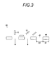
- FIG. 3 is a cross-sectional view showing the size relationship between the filter medium 40 and the fibers 10.
- the filter medium 40 composed of a plate material includes an opening 42 and a non-opening 44.
- the short axis width W ⁇ b> 2 of the opening 42 is not less than half the average major axis length of the fiber and not more than five times the average major axis length of the fiber 10.
- the minor axis width W2 of the opening 42 is not less than the average major axis length of the fiber 10 and not more than three times the average major axis length of the fiber 10.
- the minor axis width W2 of the opening 42 is not less than the average major axis length of the fiber 10 and not more than twice the average major axis length of the fiber 10.
- the minimum width W1 of the non-opening 44 is equal to or greater than the average major axis length of the fiber 10.
- the minimum width W1 of the non-opening 44 is at least twice the average major axis length of the fiber 10. Further, preferably, the minimum width W1 of the non-opening 44 is not less than three times the average major axis length of the fiber 10.
- the opening ratio of the filter medium 40 is 0.9% or more.
- the aperture ratio of the filter medium 40 is 1.5% or more and 60% or less.
- the aperture ratio of the filter medium 40 is 2.0% or more and 50% or less.
- the filter medium 40 By using the filter medium 40 as a single-layer board, it is possible to suppress the fibers 10 from being entangled with the filter medium 40.
- the filter medium 40 can also be composed of a plurality of single-layer plates.
- the opening 42 and the non-opening 44 do not overlap in a plan view. This is because if the opening 42 and the non-opening 44 overlap, there is a high possibility that the effective aperture ratio becomes extremely small, and the pressure loss increases.
- the filter medium 40 preferably has a thickness that maintains strength (pressure resistance) and has a pressure loss that is practically acceptable.
- the Reynolds number Re of the coarse dispersion 20 is preferably 2300 or less.
- the Reynolds number Re is 1500 or less. More preferably, the Reynolds number Re is 1000 or less.
- the coarse dispersion 20 is passed through the filter medium 40 in a laminar flow state within the range of the Reynolds number Re described above. Thereby, the fiber 10 in which the coarse dispersion 20 is contained is oriented along the flow direction. As a result, the short axis of the fiber 10 becomes substantially orthogonal to the opening 42, and the fiber 10 can easily pass through the opening 42.
- the Reynolds number Re is obtained by the following equation.
- kinematic viscosity of the coarse dispersion containing fibers can be measured by the following method.
- the kinematic viscosity is measured using the density of the coarse dispersion measured by a portable density meter (manufactured by Anton Paar, DMA35N) and the absolute viscosity measured by a tuning fork viscometer (manufactured by A & D, SV-10). It is calculated by the following formula.
- the pipe 50 for installing the filter medium 40 has a diameter of d (m) (FIG. 4A).
- the average flow velocity v (m / sec) when the coarse dispersion is passed through the pipe 50 without installing the filter medium 40 in the pipe 50 is used. This average flow velocity v becomes the average flow velocity immediately before the filter medium.
- the filter medium 40 is installed in the pipe 50, and the aperture ratio ⁇ of the filter medium 40 is obtained (FIG. 4B).
- FIG. 5A is a partial perspective view of the filter medium 40 having a mesh pattern.
- the filter medium 40 includes a plurality of openings 42 having substantially the same shape.
- the opening 42 has a quadrangular shape in plan view, but is not limited thereto. For example, it may be circular or polygonal. Furthermore, the opening 42 may be continuously connected and enlarged to form a slit shape.
- the filter medium 40 having a mesh pattern can be manufactured using a known electroforming technique.
- the filter medium 40 having a mesh pattern is made of metal, for example, nickel or copper.
- FIG. 5B is a plan view of the filter medium 40 having the mesh pattern of FIG.
- FIG. 6A is a partial perspective view of the filter medium 40 configured with a wedge wire screen.
- the filter medium 40 includes a plurality of wedge wires 46.
- the adjacent wedge wire 46 forms the opening 42, and the wedge wire 46 forms the non-opening 44.
- the wedge wire 46 has a wedge shape that tapers from the upstream side to the downstream side of the flow of the coarse dispersion 20.
- the wedge wire 46 is made of metal, for example, stainless steel SUS304, SUS316, or the like.
- FIG. 6B is a plan view of the filter medium 40 constituted by a wedge wire screen.
- the filter medium 40 shown in FIGS. 5 and 6 is preferably a plate material that has been subjected to a hydrophobic treatment. By subjecting the filter medium 40 to a hydrophobic treatment, the fibers 10 can be prevented from being adsorbed by the filter medium 40.
- Hydrophobic treatment may be performed by either coating or painting of a hydrophobic material such as Teflon (registered trademark) or a method of chemically modifying a hydrophobic group.
- the relationship between the shape of the opening 42 and the short axis width of the opening 42 and the relationship between the shape of the non-opening 44 and the minimum width of the non-opening 44 will be described.
- the short axis width of the opening 42 or the minimum width of the non-opening 44 is the diameter of the circle.
- the short axis width of the opening 42 or the minimum width of the non-opening 44 is a short side.
- the short axis width of the opening 42 or the minimum width of the non-opening 44 is between two straight lines when sandwiched between two straight lines parallel to the maximum length.
- the maximum length means the maximum length between any two points on the outline of the opening 42 or the non-opening 44.
- the relationship between the shape of the opening 42 and the short axis width of the opening 42 and the relationship between the shape of the non-opening 44 and the minimum width of the non-opening 44 will be described.
- the minor axis width of the opening 42 is the diameter of the circle
- the minimum width of the non-opening 44 is the distance between the circle of the opening 42 and the circle of the other opening 42, Set to the minimum value.
- the short axis width of the opening 42 is a short side
- the minimum width of the non-opening 44 is the distance between the square or rectangular opening 42 and another square or rectangular opening 42. Of these, the minimum value is used.
- the short axis width of the opening 42 is assumed to be two straight lines parallel to the longest side of the polygon, and the polygon of the opening just enters between the two straight lines. Determine the distance between the two straight lines. The distance between the two straight lines at this time is defined as the short axis width of the opening 42.
- the minimum width of the non-opening 44 is set to the minimum value among the distances between the polygonal opening 42 and the polygonal opening 42.
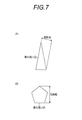
- the opening is an isosceles triangle
- two straight lines parallel to the longest side are assumed as shown in FIG.
- the isosceles triangle is placed just between the two straight lines, and the distance between the two straight lines at this time is the short axis width of the opening.
- a conductive layer containing a specific sol-gel cured product and conductive fibers as a matrix is prepared by preparing a coating solution for forming a conductive layer in which a dispersion containing conductive fibers contains an alkoxide compound.
- the coating liquid for layer formation is applied to form a liquid film of the coating liquid, and the alkoxide compound in the liquid film is hydrolyzed and polycondensed to obtain a sol-gel cured product.
- the coating liquid for forming the conductive layer is preferably prepared by mixing a dispersion of conductive fibers (for example, an aqueous solution containing silver nanowires in a dispersed manner) and an aqueous solution containing an alkoxide compound.
- a silver nanowire dispersion liquid (1) was prepared as follows. Stearyltrimethylammonium bromide powder 1.3 g, sodium bromide powder 33.1 g, glucose powder 1,000 g, and nitric acid (1N) 115.0 g were dissolved in 12.7 kg of distilled water at 80 ° C. While this liquid was kept at 80 ° C. and stirred at 500 rpm, the additive liquid A was added sequentially at an addition rate of 250 ml / min, the additive liquid B was 500 ml / min, and the additive liquid C was added at 500 ml / min. The stirring speed was 200 rpm and heating was performed at 80 ° C.
- ultrafiltration was performed as follows. After the feed liquid 102 is concentrated four times, the addition and concentration of a mixed solution of distilled water and 1-propanol (volume ratio of 1: 1) is repeated until the conductivity of the filtrate finally becomes 50 ⁇ S / cm or less. It was. The obtained filtrate was concentrated to obtain a silver nanowire aqueous dispersion (1) having a metal content of 0.45%.
- the silver nanowires had an average minor axis length of 18 nm and an average major axis length of 8 ⁇ m.
- An alkoxide compound solution having the following composition (hereinafter also referred to as a sol-gel solution) was stirred at 60 ° C. for 1 hour to confirm that the solution became uniform.
- the kinematic viscosity was 5.8 ⁇ 10 ⁇ 6 (m 2 / sec).
- the horizontal width of the non-opening and the vertical width of the non-opening are 10 ⁇ m, which is the minimum width of the non-opening. Further, when the horizontal width of the non-opening portion and the vertical width of the non-opening portion are different, the shorter one is the minimum width of the non-opening portion.
- the aperture ratio was obtained based on the calculation formula described with reference to FIG. The aperture ratio was 11.1%.
- the average flow velocity just before the filter medium is 2 (mm / sec)
- the diameter of the pipe for installing the filter medium is 0.022 m
- the kinematic viscosity of the coarse dispersion containing fibers is 5.8 ⁇ 10 ⁇ 6 (m 2 / sec.
- the Re number was 68.
- the filter medium was not hydrophobized. 1000 mL of the rough coating liquid for forming a conductive layer (coarse dispersion) was filtered under the above-mentioned conditions to obtain a conductive layer forming coating liquid (dispersion).
- Tests 2 to 13 In the same manner as in Test 1, the obtained rough coating liquid for forming a conductive layer (coarse dispersion) was supplied to a filter using an electroformed mesh plate as a filter medium to form a conductive layer in Tests 2 to 13 A coating liquid (dispersion liquid) was obtained. Conditions such as the filter medium and the Re number in Tests 2 to 13 are as shown in Table 1.
- the minor axis width of the opening is 5 ⁇ m
- the minor axis width of the nth opening is 5 ⁇ m (all minor axis widths of the openings are 5 ⁇ m)
- the lateral width (minimum width) of the non-opening is 500 ⁇ m
- the lateral width (minimum width) of the nth non-opening portion was 500 ⁇ m (the minimum widths of the non-opening portions were all 500 ⁇ m).
- the aperture ratio was obtained based on the calculation formula described with reference to FIG. The aperture ratio was 0.99%.
- the average flow velocity just before the filter medium is 2 (mm / sec)
- the diameter of the pipe for installing the filter medium is 0.022 m
- the kinematic viscosity of the coarse dispersion containing fibers is 5.8 ⁇ 10 ⁇ 6 (m 2 / sec.
- the Re number was 758.
- the filter medium was not hydrophobized. 1000 mL of the rough coating liquid for forming a conductive layer (coarse dispersion) was filtered under the above-mentioned conditions to obtain a conductive layer forming coating liquid (dispersion).
- Tests 15 to 23 In the same manner as in Test 14, the obtained rough coating liquid for forming a conductive layer (coarse dispersion) was supplied to a filter using a plate material composed of a wedge wire screen as a filter medium. A coating liquid (dispersion liquid) for forming a conductive layer was obtained. Conditions such as the filter medium and the Re number in tests 15 to 23 are as shown in Table 2.
- Test 18 and Test 22 include a case where the width of an arbitrary n-th non-opening is 1000 ⁇ m and there are a plurality of portions where the width of the non-opening is 1000 ⁇ m. Accordingly, the number of non-opening portions having a width of 500 ⁇ m and the number of non-opening portions having a width of 1000 ⁇ m are determined so that the opening ratios are 1.00% and 0.50%, respectively.
- 500 ⁇ m is 1/50
- 1000 ⁇ m is 49/50.
- 500 ⁇ m is 1/100
- 1000 ⁇ m is 99/100.
- the obtained rough coating liquid for forming a conductive layer (coarse dispersion) is supplied to a filter using a non-woven sheet filter as a filter medium, and the coating liquid for forming a conductive layer (dispersion) for tests 24 and 25 is used. Obtained.
- a sheet filter an FNC filter manufactured by MAHLE FILTER SYSTEMS CO., LTD. was used. Conditions in the tests 24 and 25 such as the filter medium and the Re number are as shown in Table 2.
- Frtration pressure change The pressure on the primary side of the filter during filtration was measured. The difference was measured from the filtration pressure change from the filtration start time to the filtration end time, and the following ranking was performed.
- the P2 dilution shown below was added to each of the rough coating liquid for forming a conductive layer before filtration and the coating liquid for forming a conductive layer after filtration, and diluted 5-fold. After dissolving silver in each of the obtained diluted solutions, it was further diluted 10 times with pure water to prepare silver nanowire dissolved solutions, respectively. The amount of silver in each silver nanowire solution is measured using an ICP emission spectrometer, and the reduction rate is calculated.
- a bleach-fixing agent for color paper processing (CP-48S-P2-A agent, B agent manufactured by FUJIFILM Corporation) and pure water were mixed in the following amounts to obtain a P2 diluted solution.
- the conductive layer-forming coating solution after filtration was measured with an image analysis type particle size distribution meter (FPIA 2100 manufactured by Malvern), and the number of foreign matters in 1 ⁇ L was counted. This was carried out 10 times and the average value was determined. The following ranking was performed.
- the conductive fiber is defined as “conductive particles having a minor axis length of 1 nm to 150 nm and a major axis length of 1 ⁇ m to 30 ⁇ m”, and the foreign matter does not correspond to the conductive fiber. Defined as a solid.
- tests 1 to 8 and 13 are as follows: (1) The minor axis width of the opening is not less than 1/2 the average major axis length of the fiber and not more than five times the average major axis length of the fiber. (2) The minimum width of the non-opening portion satisfies the requirement that the average major axis length of the fiber or more, and (3) the aperture ratio of the filter medium satisfies 0.9% or more. As a result, Tests 1 to 8 and 13 obtained an evaluation of B or higher in each evaluation. The smaller the minor axis width of the opening, the better the results in evaluating the number of foreign substances in the liquid.
- the evaluation was A in the evaluation of the number of foreign matters in the liquid.
- Test 1 in which the minor axis width of the opening is smaller than the average major axis length of the fiber, the filtration pressure change and the silver concentration reduction rate were evaluated as B.
- the larger the aperture ratio the more favorable results were obtained in the evaluation of filtration pressure change and silver concentration reduction rate.
- the larger the aperture ratio the opposite result in the number of foreign substances in the liquid.
- the filtration pressure change, the silver concentration reduction rate, and the number of foreign substances in the liquid are in a trade-off relationship.
- Tests 1 to 8 and 13 Test 2, Test 5 and Test 8 were evaluated as A in all evaluations.
- Test 1 and Test 8 are compared, only the presence or absence of the hydrophobic treatment of the filter medium is different.
- Test 8 in which the filter medium was hydrophobized a better result than Test 1 was obtained in the evaluation of the filtration pressure change and the silver concentration reduction rate.
- test 2 test 7 and test 13 are compared, only the Re number is different.
- the Re number the smaller the Re number, the particularly preferable results were obtained in the evaluation of the filtration pressure change and the silver concentration reduction rate when the Re number was 1000 or less.
- Test 9 since the minor axis width of the opening is less than half the average major axis length of the fiber and the opening ratio is less than 0.9%, the filtration pressure change and the silver concentration reduction rate In evaluation, it was evaluation of C.
- Test 10 since the minor axis width of the opening was larger than five times the average major axis length of the fiber, the evaluation was C in the evaluation of the number of foreign substances in the liquid.
- Test 11 since the width (minimum width) of the non-opening portion was smaller than the average major axis length of the fiber, the evaluation was C in the evaluation of the silver concentration reduction rate.
- Test 12 since the opening ratio was smaller than 0.9%, it was evaluated as C in the evaluation of the filtration pressure change.
- tests 14 to 20 and 23 are: (1) The minor axis width of the opening is not less than 1/2 the average major axis length of the fiber and not more than five times the average major axis length of the fiber. (2) The minimum width of the non-opening portion satisfies the requirement that the average major axis length of the fiber or more, and (3) the aperture ratio of the filter medium satisfies 0.9% or more. As a result, the tests 14 to 20 and 23 obtained an evaluation of B or higher in each evaluation. The smaller the minor axis width of the opening, the better the results in evaluating the number of foreign substances in the liquid.
- the larger the aperture ratio the more favorable results were obtained in the evaluation of filtration pressure change and silver concentration reduction rate.
- the larger the aperture ratio the opposite result in the number of foreign substances in the liquid.
- the filtration pressure change, the silver concentration reduction rate, and the number of foreign substances in the liquid are in a trade-off relationship.
- Test 15 and Test 20 gave A evaluations in all evaluations.
- Test 14 When comparing Test 14 and Test 20, only the presence or absence of the hydrophobic treatment of the filter medium is different. In the test 20 subjected to the hydrophobization treatment, more preferable results than the test 14 were obtained in the evaluation of the change in filtration pressure and the silver concentration reduction rate.
- Test 24 was an evaluation of C in the evaluation of the filtration pressure change and the silver concentration reduction rate.
- Test 25 was an evaluation of C in the evaluation of the silver concentration reduction rate and the number of foreign substances in the liquid.
Landscapes
- Engineering & Computer Science (AREA)
- Chemical & Material Sciences (AREA)
- Nanotechnology (AREA)
- Chemical Kinetics & Catalysis (AREA)
- Materials Engineering (AREA)
- Physics & Mathematics (AREA)
- General Physics & Mathematics (AREA)
- Composite Materials (AREA)
- Crystallography & Structural Chemistry (AREA)
- General Engineering & Computer Science (AREA)
- Textile Engineering (AREA)
- Theoretical Computer Science (AREA)
- General Chemical & Material Sciences (AREA)
- Condensed Matter Physics & Semiconductors (AREA)
- Inorganic Chemistry (AREA)
- Life Sciences & Earth Sciences (AREA)
- Wood Science & Technology (AREA)
- Organic Chemistry (AREA)
- Manufacturing & Machinery (AREA)
- Human Computer Interaction (AREA)
- Powder Metallurgy (AREA)
- Manufacture Of Metal Powder And Suspensions Thereof (AREA)
- Inorganic Fibers (AREA)
- Conductive Materials (AREA)
- Manufacturing Of Electric Cables (AREA)
- Filtering Materials (AREA)
Priority Applications (2)
| Application Number | Priority Date | Filing Date | Title |
|---|---|---|---|
| JP2014525758A JP5875686B2 (ja) | 2012-07-19 | 2013-06-13 | 繊維を含む分散液の製造方法、及び導電性層の製造方法。 |
| US14/565,570 US20150125592A1 (en) | 2012-07-19 | 2014-12-10 | Manufacturing method of fiber-containing dispersion, conductive fiber-containing dispersion, and manufacturing method of conductive layer |
Applications Claiming Priority (2)
| Application Number | Priority Date | Filing Date | Title |
|---|---|---|---|
| JP2012-160668 | 2012-07-19 | ||
| JP2012160668 | 2012-07-19 |
Related Child Applications (1)
| Application Number | Title | Priority Date | Filing Date |
|---|---|---|---|
| US14/565,570 Continuation US20150125592A1 (en) | 2012-07-19 | 2014-12-10 | Manufacturing method of fiber-containing dispersion, conductive fiber-containing dispersion, and manufacturing method of conductive layer |
Publications (1)
| Publication Number | Publication Date |
|---|---|
| WO2014013819A1 true WO2014013819A1 (fr) | 2014-01-23 |
Family
ID=49948654
Family Applications (1)
| Application Number | Title | Priority Date | Filing Date |
|---|---|---|---|
| PCT/JP2013/066361 Ceased WO2014013819A1 (fr) | 2012-07-19 | 2013-06-13 | Procédé de fabrication de liquide en dispersion contenant des fibres, liquide en dispersion contenant des fibres conductrices, et procédé de fabrication de couche conductrice |
Country Status (3)
| Country | Link |
|---|---|
| US (1) | US20150125592A1 (fr) |
| JP (1) | JP5875686B2 (fr) |
| WO (1) | WO2014013819A1 (fr) |
Cited By (4)
| Publication number | Priority date | Publication date | Assignee | Title |
|---|---|---|---|---|
| CN106238742A (zh) * | 2015-06-12 | 2016-12-21 | 陶氏环球技术有限责任公司 | 制造高纵横比银纳米线的方法 |
| CN106238746A (zh) * | 2015-06-12 | 2016-12-21 | 陶氏环球技术有限责任公司 | 用于制造经过滤银纳米线的水热法 |
| JP2022531091A (ja) * | 2019-04-24 | 2022-07-06 | カナトゥ オイ | 配向堆積のための装置及び方法 |
| JP2023039281A (ja) * | 2021-09-08 | 2023-03-20 | 東洋スクリーン工業株式会社 | 金属フィルタ、および、フィルタモジュール |
Families Citing this family (2)
| Publication number | Priority date | Publication date | Assignee | Title |
|---|---|---|---|---|
| WO2019121827A1 (fr) * | 2017-12-19 | 2019-06-27 | Rhodia Operations | Utilisation de milieux de filtration pour la purification de nanofils et procédé de purification de nanofils |
| WO2019121828A1 (fr) * | 2017-12-19 | 2019-06-27 | Rhodia Operations | Utilisation de milieux de filtration pour la purification de nanofils et procédé de purification de nanofils |
Citations (2)
| Publication number | Priority date | Publication date | Assignee | Title |
|---|---|---|---|---|
| WO2009063744A1 (fr) * | 2007-11-16 | 2009-05-22 | Konica Minolta Holdings, Inc. | Procédé de production de nanofil métallique, nanofil métallique et conducteur transparent |
| WO2009107694A1 (fr) * | 2008-02-27 | 2009-09-03 | 株式会社クラレ | Procédé de production d'un nanofil métallique, et dispersion et film électroconducteur transparent comprenant le nanofil métallique produit |
Family Cites Families (4)
| Publication number | Priority date | Publication date | Assignee | Title |
|---|---|---|---|---|
| US7938996B2 (en) * | 2004-10-01 | 2011-05-10 | Board Of Regents, The University Of Texas System | Polymer-free carbon nanotube assemblies (fibers, ropes, ribbons, films) |
| US9114340B2 (en) * | 2008-04-05 | 2015-08-25 | Stevenson Group Limited | Liquid removal apparatus with moving transport deck for filter belt |
| GB0908300D0 (en) * | 2009-05-14 | 2009-06-24 | Dupont Teijin Films Us Ltd | Polyester films |
| US20120126181A1 (en) * | 2010-11-22 | 2012-05-24 | Whitcomb David R | Nanowire preparation methods, compositions, and articles |
-
2013
- 2013-06-13 WO PCT/JP2013/066361 patent/WO2014013819A1/fr not_active Ceased
- 2013-06-13 JP JP2014525758A patent/JP5875686B2/ja active Active
-
2014
- 2014-12-10 US US14/565,570 patent/US20150125592A1/en not_active Abandoned
Patent Citations (2)
| Publication number | Priority date | Publication date | Assignee | Title |
|---|---|---|---|---|
| WO2009063744A1 (fr) * | 2007-11-16 | 2009-05-22 | Konica Minolta Holdings, Inc. | Procédé de production de nanofil métallique, nanofil métallique et conducteur transparent |
| WO2009107694A1 (fr) * | 2008-02-27 | 2009-09-03 | 株式会社クラレ | Procédé de production d'un nanofil métallique, et dispersion et film électroconducteur transparent comprenant le nanofil métallique produit |
Cited By (8)
| Publication number | Priority date | Publication date | Assignee | Title |
|---|---|---|---|---|
| CN106238742A (zh) * | 2015-06-12 | 2016-12-21 | 陶氏环球技术有限责任公司 | 制造高纵横比银纳米线的方法 |
| CN106238746A (zh) * | 2015-06-12 | 2016-12-21 | 陶氏环球技术有限责任公司 | 用于制造经过滤银纳米线的水热法 |
| CN106238742B (zh) * | 2015-06-12 | 2018-07-20 | 陶氏环球技术有限责任公司 | 制造高纵横比银纳米线的方法 |
| CN106238746B (zh) * | 2015-06-12 | 2018-07-20 | 陶氏环球技术有限责任公司 | 用于制造经过滤银纳米线的水热法 |
| JP2022531091A (ja) * | 2019-04-24 | 2022-07-06 | カナトゥ オイ | 配向堆積のための装置及び方法 |
| JP7649249B2 (ja) | 2019-04-24 | 2025-03-19 | カナトゥ フィンランド オイ | 配向堆積のための装置及び方法 |
| JP2023039281A (ja) * | 2021-09-08 | 2023-03-20 | 東洋スクリーン工業株式会社 | 金属フィルタ、および、フィルタモジュール |
| JP7778306B2 (ja) | 2021-09-08 | 2025-12-02 | 東洋スクリーン工業株式会社 | 金属フィルタ、および、フィルタモジュール |
Also Published As
| Publication number | Publication date |
|---|---|
| US20150125592A1 (en) | 2015-05-07 |
| JP5875686B2 (ja) | 2016-03-02 |
| JPWO2014013819A1 (ja) | 2016-06-30 |
Similar Documents
| Publication | Publication Date | Title |
|---|---|---|
| JP5875686B2 (ja) | 繊維を含む分散液の製造方法、及び導電性層の製造方法。 | |
| Ávila-Bolívar et al. | Electrochemical reduction of CO2 to formate on easily prepared carbon-supported Bi nanoparticles | |
| Niu et al. | Synthesis of silver nanowires with reduced diameters using benzoin-derived radicals to make transparent conductors with high transparency and low haze | |
| Chen et al. | Mechanically strong, optically transparent, giant metal superlattice nanomembranes from ultrathin gold nanowires | |
| TWI710400B (zh) | 純化奈米結構之方法 | |
| Chitranshi et al. | Carbon nanotube sheet-synthesis and applications | |
| Sreeprasad et al. | Tellurium nanowire-induced room temperature conversion of graphite oxide to leaf-like graphenic structures | |
| CN103945960A (zh) | 中空金属纳米粒子 | |
| Basu et al. | Graphene–noble metal nano-composites and applications for hydrogen sensors | |
| Mendoza-Cruz et al. | Helical growth of ultrathin gold–copper nanowires | |
| CN104884194A (zh) | 负载在载体上的中空金属纳米粒子 | |
| Mittal et al. | The effects of cryomilling CNTs on the thermal and electrical properties of CNT/PMMA composites | |
| US20180065854A1 (en) | Carbon film and method for producing same | |
| Kim et al. | Plasma-assisted electrochemical synthesis of monodisperse Au and Au@ Ag core–shell nanoparticles | |
| EP3745423A1 (fr) | Encre à nanofils d'argent et son procédé de fabrication | |
| Luo et al. | Efficient sizing of single layer graphene oxide with optical microscopy under ambient conditions | |
| Alterary et al. | Fabrication of novel buckypaper metal oxide nano-catalysis glycerol carbonate/MWCNTs membrane for efficient removal of heavy metals | |
| Masyutin et al. | Wall thickness of industrial multi-walled carbon nanotubes is not a crucial factor for their degradation by sodium hypochlorite | |
| Dumee et al. | Control of porosity and pore size of metal reinforced carbon nanotube membranes | |
| Guevara et al. | Parametric effects of mechanical alloying on carbon nanofiber catalyst production in the Ni-Cu system | |
| JP6956599B2 (ja) | 金属ナノワイヤ転写用の金属ナノワイヤ付支持基材及び透明導電フィルムの製造方法 | |
| Yang et al. | Low-temperature vapor-phase synthesis of single-crystalline gold nanostructures: Toward exceptional electrocatalytic activity for methanol oxidation reaction | |
| JP2012216411A (ja) | ナノ粒子含有層の製造方法及びその製造装置、並びに導電性構造物の製造方法及びその製造装置 | |
| Maraschin et al. | Few-layer graphene production through graphite exfoliation in pressurized CO2 assisted by natural surfactant | |
| Chajanovsky et al. | Preparation of hybrid polyaniline/nanoparticle membranes for water treatment using an inverse emulsion polymerization technique under sonication |
Legal Events
| Date | Code | Title | Description |
|---|---|---|---|
| 121 | Ep: the epo has been informed by wipo that ep was designated in this application |
Ref document number: 13820201 Country of ref document: EP Kind code of ref document: A1 |
|
| ENP | Entry into the national phase |
Ref document number: 2014525758 Country of ref document: JP Kind code of ref document: A |
|
| NENP | Non-entry into the national phase |
Ref country code: DE |
|
| 122 | Ep: pct application non-entry in european phase |
Ref document number: 13820201 Country of ref document: EP Kind code of ref document: A1 |