WO2014013870A1 - リニアアクチュエータ - Google Patents
リニアアクチュエータ Download PDFInfo
- Publication number
- WO2014013870A1 WO2014013870A1 PCT/JP2013/068221 JP2013068221W WO2014013870A1 WO 2014013870 A1 WO2014013870 A1 WO 2014013870A1 JP 2013068221 W JP2013068221 W JP 2013068221W WO 2014013870 A1 WO2014013870 A1 WO 2014013870A1
- Authority
- WO
- WIPO (PCT)
- Prior art keywords
- shaft
- linear actuator
- motor
- worm
- clutch
- Prior art date
- Legal status (The legal status is an assumption and is not a legal conclusion. Google has not performed a legal analysis and makes no representation as to the accuracy of the status listed.)
- Ceased
Links
Images


Classifications
-
- H—ELECTRICITY
- H02—GENERATION; CONVERSION OR DISTRIBUTION OF ELECTRIC POWER
- H02K—DYNAMO-ELECTRIC MACHINES
- H02K7/00—Arrangements for handling mechanical energy structurally associated with dynamo-electric machines, e.g. structural association with mechanical driving motors or auxiliary dynamo-electric machines
- H02K7/10—Structural association with clutches, brakes, gears, pulleys or mechanical starters
- H02K7/116—Structural association with clutches, brakes, gears, pulleys or mechanical starters with gears
- H02K7/1163—Structural association with clutches, brakes, gears, pulleys or mechanical starters with gears where at least two gears have non-parallel axes without having orbital motion
- H02K7/1166—Structural association with clutches, brakes, gears, pulleys or mechanical starters with gears where at least two gears have non-parallel axes without having orbital motion comprising worm and worm-wheel
-
- A—HUMAN NECESSITIES
- A61—MEDICAL OR VETERINARY SCIENCE; HYGIENE
- A61G—TRANSPORT, PERSONAL CONVEYANCES, OR ACCOMMODATION SPECIALLY ADAPTED FOR PATIENTS OR DISABLED PERSONS; OPERATING TABLES OR CHAIRS; CHAIRS FOR DENTISTRY; FUNERAL DEVICES
- A61G7/00—Beds specially adapted for nursing; Devices for lifting patients or disabled persons
- A61G7/002—Beds specially adapted for nursing; Devices for lifting patients or disabled persons having adjustable mattress frame
- A61G7/018—Control or drive mechanisms
-
- H—ELECTRICITY
- H02—GENERATION; CONVERSION OR DISTRIBUTION OF ELECTRIC POWER
- H02K—DYNAMO-ELECTRIC MACHINES
- H02K11/00—Structural association of dynamo-electric machines with electric components or with devices for shielding, monitoring or protection
- H02K11/0094—Structural association with other electrical or electronic devices
-
- H—ELECTRICITY
- H02—GENERATION; CONVERSION OR DISTRIBUTION OF ELECTRIC POWER
- H02K—DYNAMO-ELECTRIC MACHINES
- H02K13/00—Structural associations of current collectors with motors or generators, e.g. brush mounting plates or connections to windings; Disposition of current collectors in motors or generators; Arrangements for improving commutation
- H02K13/10—Arrangements of brushes or commutators specially adapted for improving commutation
-
- H—ELECTRICITY
- H02—GENERATION; CONVERSION OR DISTRIBUTION OF ELECTRIC POWER
- H02K—DYNAMO-ELECTRIC MACHINES
- H02K23/00—DC commutator motors or generators having mechanical commutator; Universal AC/DC commutator motors
- H02K23/26—DC commutator motors or generators having mechanical commutator; Universal AC/DC commutator motors characterised by the armature windings
- H02K23/38—DC commutator motors or generators having mechanical commutator; Universal AC/DC commutator motors characterised by the armature windings having winding or connection for improving commutation, e.g. equipotential connection
-
- H—ELECTRICITY
- H02—GENERATION; CONVERSION OR DISTRIBUTION OF ELECTRIC POWER
- H02K—DYNAMO-ELECTRIC MACHINES
- H02K3/00—Details of windings
- H02K3/04—Windings characterised by the conductor shape, form or construction, e.g. with bar conductors
- H02K3/28—Layout of windings or of connections between windings
-
- H—ELECTRICITY
- H02—GENERATION; CONVERSION OR DISTRIBUTION OF ELECTRIC POWER
- H02K—DYNAMO-ELECTRIC MACHINES
- H02K7/00—Arrangements for handling mechanical energy structurally associated with dynamo-electric machines, e.g. structural association with mechanical driving motors or auxiliary dynamo-electric machines
- H02K7/06—Means for converting reciprocating motion into rotary motion or vice versa
Definitions
- the present invention relates to a linear actuator having a linear drive configuration, and more particularly to a feed screw type linear actuator using an electric motor having a 4-pole 2-brush configuration.
- Patent Document 1 describes a linear actuator that extends and contracts a piston using a ball screw mechanism.
- the rotation of the electric motor is decelerated by a worm and a worm wheel and transmitted to the drive shaft.
- the rotation of the drive shaft is converted into a linear motion by the ball screw mechanism, and the piston expands and contracts.
- the linear actuator of patent document 1 is used for reclining the back bottom of the bed, and is connected to the link mechanism of the bed.
- the link mechanism spreads, the back bottom of the bed rises and enters an inclined state (see FIG. 1B).
- the piston contracts the link mechanism is folded, the back bottom is brought down to the horizontal position, and the bed is in a flat state (see FIG. 1A).
- linear actuators used in electric beds are designed to reduce the bed from the viewpoint of user convenience and safety, and the actuator placed under the bottom is required to be smaller and thinner. ing.
- the motor is downsized, the output torque is reduced accordingly, and in order to obtain the same driving force as before, it is necessary to increase the rotational speed and set a large reduction ratio.
- it is necessary to increase the number of teeth of the worm wheel in the reduction mechanism. Therefore, as the number of teeth increases, the outer diameter of the worm wheel becomes larger, which causes a problem that it is disadvantageous for lowering the bed. Further, when the motor is rotated at a high speed, there is a problem that the operation noise increases.
- a small motor capable of exhibiting high torque without increasing the operating noise is required.
- the linear actuator according to the present invention includes a shaft having a male screw portion, a worm and a worm wheel that transmit the rotation of the motor at a reduced speed to the shaft, and a screw that is screwed into the male screw portion and advances and retreats by forward and reverse rotation of the shaft.
- a linear actuator comprising a nut and a piston tube that is fixed to the screw nut and advances and retreats with respect to the housing, wherein the motor is a four-pole field magnetic pole fixed to the inner circumferential surface of the yoke;
- An armature in which armature windings are wound with multiple windings, a commutator disposed on the armature, and electrically connected to the armature windings, are disposed at approximately 90 ° intervals, and is disposed on the surface of the commutator.
- Two brushes in contact with each other, a plurality of coils connected to the commutator and forming the armature winding, And characterized by having a equalizing for connecting the coils to be the Chi like potential.
- a feed screw type linear actuator using an electric motor employs a motor with a four-pole, two-brush configuration with a pressure equalizing line around which armature windings are wound.
- the motor can be miniaturized, and the linear actuator can be miniaturized while being able to exhibit the same function as the conventional actuator.
- the two brushes may be arranged such that brushes of different poles are arranged in a vertical relationship such that the positive electrode is on the top and the negative electrode is on the bottom, for example.
- a multi-row worm having two or more stripes may be used as the worm.
- a multi-row worm having two or more stripes for example, a two-row worm
- the rotation speed of the worm wheel can be ensured as before. Therefore, the number of rotations of the motor can be reduced as compared with the case where a single worm is used, and the operating noise during motor operation can be suppressed accordingly.
- the motor that is the driving source is a 4-pole 2-brush configuration in which the armature windings are overwrapped, so that the motor is smaller than the conventional linear actuator.
- the linear actuator can be miniaturized. Therefore, for example, by using the linear actuator for an electric bed, the bed can be lowered.
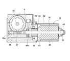
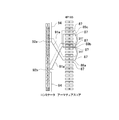
- FIG. 3 is an enlarged sectional view taken along line AA in FIG. 2.
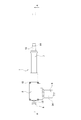
- FIG. 1 is an explanatory view showing a use state of a linear actuator 1 according to an embodiment of the present invention
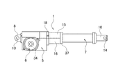
- FIG. 2 is a plan view showing the entire structure of the linear actuator 1
- FIG. 3 is a front view thereof
- FIG. FIG. 10 is an enlarged cross-sectional view taken along the line A.
- the linear actuator 1 according to the present invention is a feed screw type actuator using an electric motor.
- the linear actuator 1 is used as a drive source for raising and lowering a bed (back bottom 3) on the back of a medical / care bed 2 (hereinafter abbreviated as bed 2).
- the linear actuator 1 is attached to the frame 4 of the bed 2 and is disposed under the bed.
- the linear actuator 1 includes a main body housing 5, a motor unit 6, and a piston unit 7. As shown in FIG. 1, the linear actuator 1 is attached to the bed 2 with the main body housing 5 on the fixed side and the piston unit 7 on the free end side.
- the main body housing 5 is attached to the frame 4 via a clevis 8.
- the clevis 8 is rotatably attached to the frame 4 around an actuator support shaft 9 (hereinafter abbreviated as a support shaft 9).
- a piston tube 10 is attached to the piston unit 7 so as to be able to appear and retract.
- the piston tube 10 is connected to a link 11 for raising and lowering the back bottom 3.
- the piston tube 10 is rotatably attached to the link 11 around the link connection shaft 12.
- the bed 2 has the back bottom 3 lying horizontally when the piston tube 10 is contracted.
- the back bottom 3 is in an upright state as shown in FIG.
- the back tilt angle of the back bottom 3 changes according to the extension amount of the piston tube 10.
- the back bottom 3 can be stopped and held at an arbitrary angle by appropriately controlling the linear actuator 1.
- the user or caregiver of the bed can adjust the back bottom 3 to a desired angle by operating a switch (not shown).
- a motor unit 6 as a power source is attached to the side surface of the main body housing 5.
- a piston unit 7 is attached to the right side of the main body housing 5 in the figure.
- a clevis 8 is attached to the left end side of the main body housing 5 in the drawing.
- a shaft hole 13 is provided in the clevis 8.
- the support shaft 9 is inserted into the shaft hole 13.
- the main body housing 5 is rotatably attached to the frame 4 by the clevis 8 and the support shaft 9.
- a shaft hole 14 is provided at the tip of the piston tube 10.
- the link connection shaft 12 is inserted into the shaft hole 14.
- the piston unit 7 is rotatably attached to the link 11 by the link connecting shaft 12.
- the main body housing 5 is formed in a rectangular parallelepiped shape. As shown in FIG. 3, the main body housing 5 is vertically divided into two along the axial direction. The upper side of the main body housing 5 is a first case 15, and the lower side is a second case 16.
- the main body housing 5 has a structure in which the first and second cases 15 and 16 are combined. Both the first and second cases 15 and 16 are made of synthetic resin. The first case 15 and the second case 16 are fastened by screws 18.
- a metal frame ring 37 is attached to the cylindrical portions of the first and second cases 15 and 16. Since the frame ring 37 is attached, the first and second cases 15 and 16 are not separated.
- the clevis 8 is attached to the clevis attachment portion 17 so as to be sandwiched between the first and second cases 15 and 16.
- the clevis 8 has a flange portion 8a formed in a square shape. A flange portion 8 a is inserted and clamped in the clevis mounting portion 17. In the linear actuator 1, by changing the mounting direction of the flange portion 8a, the shaft hole 13 can be set in either the vertical direction or the horizontal direction, and the degree of freedom in mounting is high.
- a piston unit housing portion 19 and a mechanism housing portion 20 are provided in the main body housing 5.
- the piston unit housing part 19 the left end side of the piston unit 7 is housed and fixed.
- the piston unit 7 includes a metal reinforcement pipe 22, a synthetic resin support pipe 23, and the piston tube 10.
- a power transmission mechanism 21 for transmitting the rotational power from the motor unit 6 to the piston tube 10 is housed in the mechanism housing portion 20.
- the power transmission mechanism 21 includes a worm wheel 41, a coupling 42, a clutch case 43, a one-way clutch 44 (hereinafter abbreviated as a clutch 44), and a brake unit 45.
- the reinforcing pipe 22 of the piston unit 7 is formed in a cylindrical shape. One end of the reinforcing pipe 22 is supported and fixed so as to be sandwiched between the first and second cases 15 and 16.
- a cylindrical support pipe 23 is inserted into the reinforcement pipe 22.
- a synthetic resin plug 24 is attached to the tip of the support pipe 23.
- a metal cap 25 is attached to the outside of the plug 24.
- a piston tube 10 and a shaft 26 that are formed in a cylindrical shape are accommodated in the support pipe 23.
- a bearing adapter 27 is attached to the left end portion of the shaft 26.
- the shaft 26 is attached to the bearing 28 via a bearing adapter 27.
- the bearing 28 is attached in the main body housing 5.
- the shaft 26 is rotatably supported in the main body housing 5 by a bearing 28.
- a washer 72 and a nut 73 are attached to the shaft 26 to prevent the bearing adapter 27 from coming off.
- the male thread portion 26a is formed on the shaft 26.
- a screw nut 29 is attached to the male screw portion 26a.
- the length of the male thread portion 26a is the same as that of the conventional actuator. Therefore, the linear actuator 1 can exhibit the same function as the conventional one (standing up / down of the back bottom 3) as an actuator.
- the screw nut 29 is screwed to the male thread portion 26a of the shaft 26 so as to be able to advance and retreat.
- a screw nut adapter 30 (hereinafter abbreviated as “adapter 30”) made of synthetic resin is attached to the screw nut 29 in a state in which it is prevented from rotating.
- a recess 31 a is formed on the inner periphery of the ring portion 31 of the adapter 30.
- a convex portion 29 a is formed on the outer periphery of the screw nut 29.
- a protrusion 32a protrudes radially inward.
- a through hole 10 a is formed at the end of the piston tube 10.
- the fitting groove 38 is formed at the base of the claw portion 32.
- the fitting groove 38 is fitted with a protrusion 39 (not shown) formed on the inner periphery of the support pipe 23 and extending in the axial direction.
- the adapter 30 is disposed so as to be movable in the axial direction in a state in which the adapter 30 is prevented from rotating in the support pipe 23 by the fitting of the fitting groove 38 and the protrusion 39.
- the piston tube 10 and the screw nut 29 are connected by the adapter 30.
- the screws do not protrude from the end face of the screw nut.
- the distance between the screw nut 29 and the power transmission mechanism 21 (worm wheel 41 or the like) can be shortened, and the overall length of the apparatus can be shortened. Therefore, according to the linear actuator 1 of the present invention, the piston stroke can be maintained equivalent to that of the conventional device while the device is downsized.
- FIG. 6 is a sectional view showing the configuration of the motor unit 6, and FIGS. 7 and 8 are explanatory diagrams showing the configuration of the motor 34.
- the rotation shaft 35 of the motor 34 is inserted into the main body housing 5 and extends into the mechanism housing portion 20.
- the rotating shaft 35 is rotatably supported by bearings 80 a and 80 b provided on the first case 15.
- a worm 36 is formed on the outer periphery of the rotary shaft 35.
- the worm 36 meshes with the worm wheel 41 of the power transmission mechanism 21.
- a multi-row worm having two or more stripes is used as the worm 36 (here, two-row worm).
- the rotational speed of the worm wheel 41 can be secured even if the rotational speed of the worm 36 is lowered. Therefore, the number of rotations of the motor can be reduced as compared with the case where a single worm is used, and the operating noise during motor operation can be suppressed accordingly.
- the motor 34 includes an armature 81 provided with a rotating shaft 35 and a bottomed cylindrical yoke 82.
- the armature 81 is accommodated in the yoke 82.
- a bearing 84 is attached to the end of the yoke 82.
- One end side of the rotating shaft 35 is rotatably supported by the bearing 84.
- two to four magnets 85 are attached to the inner peripheral surface 83 of the yoke 82 as field magnetic poles.
- the magnet 85n magnetized to the north pole on the inner peripheral side and the magnet 85s magnetized to the south pole are alternately arranged.
- the magnets 85n and 85s are fixed to the yoke inner peripheral surface 83 with an adhesive or the like.
- the motor 34 has a four-pole configuration having four magnets 85.
- the 4-pole motor 34 can secure the motor torque necessary as an actuator even if the magnet is thinner than the conventional 2-pole motor. Therefore, as the magnet 85 is made thinner, the outer diameter of the yoke 82 can be reduced, and the motor 34 can be reduced in size accordingly.
- the electric bed is required to have a low floor.
- the linear actuator is downsized due to the downsizing of the motor, and the space under the bed bottom can be made smaller. As a result, it is possible to arrange the bed bottom at a lower position (lowering the bed). Further, by making the motor 34 have a four-pole configuration, the cogging of the motor 34 is reduced and the actuator operating noise is also reduced.
- the armature 81 is disposed inside the magnet 85.
- a commutator 86 is attached to the rotary shaft 35 adjacent to the armature 81.
- the armature 81 has an armature core 88. As shown in FIG. 7, the armature core 88 includes 18 teeth 87 extending radially along the radial direction. A slot 89 is formed between the teeth 87.
- An armature coil (armature winding) 91 is wound around the slot 89.
- the armature coil 91 is wound around the slot 89 with a predetermined interval.
- Each end of the armature coil 91 is electrically connected to each commutator piece (commutator piece) 92 of the commutator 86.
- a brush 93 (93a, 93b) is in sliding contact with the commutator 86.
- FIG. 9 is an explanatory view showing a winding state of the armature coil 91.
- the armature coil 91 is wound from the commutator piece 92 a predetermined number of times between the two slots 89 with a predetermined interval, and is further spaced between the two slots 89 with a predetermined interval. Is wound a predetermined number of times. Then, it is connected to another commutator piece 92.
- the coil 91a in FIG. 9 first enters the slot 89a formed between the 8th and 9th teeth 87 from the 14th commutator piece 92a, and from there, the 12th and 13th teeth 87 are inserted.
- the slot 89b is wound a predetermined number of times (for example, 21 turns) between the slots 89b formed therebetween.
- the slot 89b is wound a predetermined number of times (for example, 21 turns) between the slot 89c formed between the 16th and 17th teeth 87.
- the slot 89b is connected to the sixth commutator piece 92b.
- the thick winding portion of the coil wound by heavy winding has half the number of turns. That is, in the above example, the 42-turn thick winding portion is 21 turns ⁇ 2, and the coil can be wound to the back of the slot. Thereby, the swelling of the coil end portion is suppressed, and the space factor of the winding can be increased correspondingly.
- the equipotential points are connected by a pressure equalizing line 94. That is, the equipotential coils facing each other of the armature coil 91 are connected by the equalizing line 94. That is, in the 18-slot motor 34, coils at positions facing each other by 180 ° across the 9 slots are connected by a pressure equalizing line 94. As a result, power is supplied to the opposing equipotential coils via the pressure equalizing line 94, and the equipotential brushes (indicated by broken lines in FIG. 8) at positions facing the brushes 93a and 93b can be reduced.
- the motor 34 can be configured in a 4-pole 2-brush configuration by means of the pressure equalizing line 94, and the motor is converted into 4-poles without deteriorating the brush sliding sound compared to the conventional 2-pole 2-brush configuration motor. 34 can be reduced in size.
- the adoption of the four-pole configuration makes it possible to reduce the size of the motor 34 and lower the bed.
- the motor 34 is made quieter than the conventional motor by reducing the operation noise by adopting a multi-row worm and reducing the cogging by quadrupole, the quietness of the linear actuator 1 is also improved.
- the actuator operating sound does not sound below the bottom. As a result, the bed bottom can be arranged lower, and the bed can be lowered from this point.
- two brushes 93a and 93b are arranged vertically (in a direction perpendicular to the floor surface) at intervals of 90 °.
- the upper (bed bottom) brush 93a is a positive (+) brush
- the lower (floor) brush 93b is a negative (-) brush. That is, in the linear actuator 1, brushes with different polarities are arranged vertically.
- brush wear powder is generated by the sliding contact between the brush and the commutator with the operation of the motor.
- brush wear powder may accumulate in the motor over many years of use.
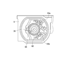
- FIG. 10 is an exploded perspective view showing the configuration of the power transmission mechanism 21.
- the power transmission mechanism 21 includes the worm wheel 41, the coupling 42, the clutch case 43, the clutch 44, and the brake unit 45.
- rotational input from the worm 36 is transmitted from the worm wheel 41 to the shaft 26 via the coupling 42.
- the piston tube 10 is pushed out and the back bottom 3 stands up.
- the clutch 44 in the power transmission mechanism 21 is in a free state (OFF state).
- the piston tube 10 moves forward without the braking action by the brake unit 45.
- the worm wheel 41 is formed in a bottomed cylindrical shape. One end side of the worm wheel 41 is opened in a cup shape. A small gear 46 is formed on the other end side of the worm wheel 41. The small gear 46 is connected to a potentiometer (not shown) for detecting rotation through a reduction gear or the like (not shown).
- the opening end side of the worm wheel 41 is a coupling fitting portion 47 having a cylindrical hole shape. On the inner peripheral portion of the coupling fitting portion 47, a plurality of fitting recesses 48 are equally formed along the circumferential direction.
- a coupling 42 made of metal (for example, an iron-based sintered alloy) is attached to the coupling fitting portion 47 in an inserted state.
- a clutch case 43 and a clutch 44 are accommodated in the coupling 42.
- the linear actuator 1 employs a structure in which the shape of the worm wheel 41 is cup-shaped and the clutch 44 and the like are accommodated therein. With this structure, the overall length of the apparatus can be reduced as compared with the conventional actuator shown in FIG. 10 in which the worm wheel 41 and the clutch 44 are arranged in series in the axial direction. Accordingly, as described above, the piston stroke can be ensured while downsizing the apparatus.
- the coupling 42 is also formed in a bottomed cylindrical shape. On the outer periphery of the coupling 42, a plurality of fitting protrusions 49 are equally formed along the circumferential direction. When the coupling 42 is attached to the coupling fitting portion 47, the fitting convex portion 49 and the fitting concave portion 48 can be inserted and fitted along the axial direction. Will fit.
- the coupling 42 is attached to the worm wheel 41 in a state in which the coupling 42 is prevented from rotating by the fitting of the convex portion 49 and the concave portion 48.
- a boss 51 is formed on the inner peripheral side of the coupling 42 so as to protrude.
- a shaft hole 52 is formed through the boss portion 51 in the axial direction.
- a serration 53 is formed on the inner peripheral surface of the shaft hole 52.
- serrations 54 are also formed on the outer periphery of the left end side of the shaft 26.
- the coupling 42 is attached to the shaft 26 in a state where both the serrations 53 and 54 are engaged with each other. Due to the engagement of the serrations 53 and 54, the coupling 42 is attached to the shaft 26 while being prevented from rotating. As a result, the worm wheel 41 is integrated with the shaft 26 via the coupling 42.
- a metal coupling 42 is built in between the worm wheel 41 and the shaft 26, and the rotational force of the worm wheel is transmitted to the shaft 26 via the coupling 42. For this reason, the strength of the worm wheel 41 can be secured by the coupling 42, and the thickness (axial length) of the worm wheel 41 can be reduced.
- the worm wheel made of synthetic resin and the metal shaft are serrated and connected, it is necessary to take a long connecting portion in order to secure the bonding strength.
- the metal coupling 42 and the shaft 26 are both serrated and connected, the length of the connecting portion can be shortened as compared with the conventional one. Can be shortened. Therefore, in the linear actuator 1 of the present invention, the piston stroke can be secured while the apparatus is downsized.
- the coupling 42 in the worm wheel 41, the inside of the tooth portion 41a of the worm wheel 41 is reinforced by the metal member. For this reason, the strength of the tooth portion 41a can be secured without increasing the outer diameter of the worm wheel 41, the diameter of the worm wheel 41 can be reduced, and the thickness of the apparatus can be reduced. Since a linear actuator for a bed is usually disposed under the bed, it is required to reduce the thickness of the apparatus in accordance with the lowering of the bed. According to the linear actuator 1 of the present invention, it is possible to meet the demand associated with such a low bed.
- the conventional actuator uses a worm wheel formed entirely of synthetic resin, reducing the axial length not only reduces the coupling strength with the shaft, but also causes the worm wheel to engage with the gear teeth. May be distorted and the meshing may become shallow. If the meshing is shallow, problems such as abnormal noise during operation and increased wear on the teeth occur.
- the linear actuator 1 since the metal member is arranged on the inner side, the worm wheel is not easily distorted, and the meshing between the worm 36 and the worm wheel 41 is stabilized. Therefore, abnormal noise and abnormal wear during operation can be suppressed, and the feeling of use of the bed can be improved and the durability of the actuator can be improved.
- a metal (for example, aluminum die-cast) clutch case 43 is inserted into the inner cylinder portion 55 of the coupling 42.
- the clutch case 43 has a cylindrical shape with both ends opened.
- a flange-shaped ring portion 56 is formed with an enlarged diameter.
- a protruding portion 57 is formed to protrude outward in the radial direction. The protruding portion 57 is engaged with a locking portion (recessed portion) (not shown) provided in the first case 15, and the protruding portion 57 is disposed in a state of being prevented from rotating with respect to the first case 15.
- the outer periphery (outer ring side) of the clutch 44 is press-fitted and fixed inside the clutch case 43.
- a one-way clutch provided with a plurality of rollers (not shown) is used.
- the clutch 44 is transmitted between the inner and outer rings only in one direction, and is transmitted to the other.
- the clutch 44 is set to be in a free state when the shaft 26 is rotating forward and to be locked when the shaft 26 is rotating backward. Yes.
- a cylindrical portion 62 of a brake plate holder 61 provided in the brake unit 45 is inserted on the inner peripheral side (inner ring side) of the clutch 44.
- the cylindrical portion 62 is an interposition member disposed between the inner ring of the clutch and the shaft 26 together with the boss portion 51 of the coupling 42.
- the clutch 44 is disposed on the shaft 26 via the boss portion 51 and the cylindrical portion 62.
- the size of the clutch 44 can be changed by adjusting the diameters of the boss portion 51 and the cylindrical portion 62, and the clutch 44 can be selected according to a desired locking force.
- the brake unit 45 includes a metal brake plate holder 61, a synthetic resin (for example, polyamide) brake plate 63, and metal brake washers 64a and 64b (two).
- Serrations 66 are formed in the shaft holes 65a and 65b of the brake washers 64a and 64b.
- the serration 66 meshes with the serration 54 of the shaft 26.
- the brake washers 64a and 64b are attached to the shaft 26 while being prevented from rotating by the engagement of the serrations 66 and 54.
- the brake washers 64a and 64b are arranged on both sides of the brake plate 63 in the axial direction so as to sandwich the brake plate 63.
- the brake plate holder 61 has a cylindrical shape with both ends opened.
- a flange portion 67 is formed on one end side of the brake plate holder 61.
- On the flange portion 67 four convex portions 68 are provided so as to protrude equally along the axial direction.
- Between the convex portions 68 is a holder concave portion 69.
- Plate convex portions 70 (four pieces) formed on the outer periphery of the brake plate 63 are fitted into the holder concave portion 69.
- the brake plate 63 and the brake plate holder 61 rotate together as a result of the fitting of the concave portion 69 and the convex portion 70.
- Concave and convex press-contact portions 71 are formed on both end surfaces of the brake plate 63.
- the pressure contact portion 71 is pressure contacted with the brake washers 64a and 64b in a slidable state. Grease is applied between the brake washers 64a and 64b and the pressure contact portion 71
- the brake unit 45 is set so that the clutch 44 is in a free state when the shaft 26 rotates forward.
- brake washers 64 a and 64 b rotate with the shaft 26.
- the brake plate 63 is also rotated by the frictional force generated in the pressure contact portion 71.
- the brake plate 63 and the brake plate holder 61 rotate together by fitting the plate convex portion 70 and the holder concave portion 69.
- the brake unit 45 is set so that the clutch is free during the forward rotation of the shaft, the brake plate holder 61 is idled in the clutch 44.
- the shaft 26 and the clutch 44 are not directly coupled, and a brake plate holder 61 is disposed inside the clutch 44.
- a boss 51 of the coupling 42 is disposed inside the brake plate holder 61.
- a shaft 26 is disposed inside the boss portion 51 of the coupling 42.
- the larger the clutch diameter the greater the locking force. Therefore, when the clutch is directly attached to the shaft as in the conventional actuator, the clutch diameter may be reduced and the locking force may be insufficient.
- the size of the clutch 44 can be adjusted regardless of the shaft diameter. Therefore, the clutch 44 can be selected in accordance with a desired locking force, the degree of freedom of design is increased, and the product reliability is also improved.
- the linear actuator 1 when the operator presses the operation button to raise the back bottom 3, the motor 34 rotates forward.
- the rotation of the motor 34 is transmitted from the worm 36 to the worm wheel 41 and the coupling 42, and the shaft 26 rotates in the forward direction.
- the shaft 26 rotates forward, the screw nut 29 moves forward, and the piston tube 10 connected to the screw nut 29 is pushed out.
- the clutch 44 is in a free state, so that only the shaft 26 rotates forward and no braking action by the brake unit 45 occurs.
- the normal rotation of the shaft 26 is transmitted from the small gear 46 to a potentiometer for detecting rotation.
- the potentiometer outputs a voltage value corresponding to the rotation angle of the shaft 26 and is transmitted to a controller (not shown) that controls the operation of the bed 2.
- the controller detects a potentio voltage corresponding to the predetermined upper limit position, the controller automatically stops the motor 34.
- the load (such as the weight of the user) of the back bottom 3 acts on the piston tube 10 and a force is applied to the screw nut 29 in a direction to retract it.
- the force in the backward direction is a force that reversely rotates the shaft 26, and the shaft 26 is reversely rotated by the load of the back bottom 3.
- the clutch 44 is locked, and a brake action is generated in the brake unit 45. That is, the brake washers 64 a and 64 b rotate with respect to the brake plate 63 while receiving a load, and a braking force is generated by the frictional force of the press contact portion 71. Thereby, the reverse rotation of the shaft 26 is prevented, and the back bottom 3 is stationary and held in a state where a load is received.
- the bearing 28 is disposed between the nut 73 and the brake washer 64a. Further, by using the bearing adapter 27, a deep groove ball bearing having a large size capable of receiving the thrust load of the shaft 26 is used for the bearing 28. Therefore, in the linear actuator 1 of the present invention, the axial force applied to the shaft 26 can be received by the inner ring 28 a of the bearing 28. That is, in the linear actuator 1, the axial force applied to the shaft 26 is transferred from the step portion 26b of the shaft 26 to the coupling 42, the brake washer 64b, the brake plate 63, the brake washer 64a, and the inner ring 28a of the bearing 28. Communicated. As a result, in the linear actuator 1, the load receiving base plate used in the conventional actuator can be eliminated, and the overall length of the apparatus can be shortened by the thickness of the base plate.
- the inner ring 28a of the bearing 28 rotates with the shaft 26, and the outer ring 28b does not rotate. Accordingly, it is possible to prevent the generation of abnormal noise caused by the sliding of the first case 15 and the bearing outer ring 28b.
- grease is applied between the bearing outer ring and the main body housing in order to prevent the generation of noise due to rotation of the bearing outer ring.
- the actuator of the present invention since the outer ring 28b of the bearing 28 does not rotate, it is not necessary to apply grease between the bearing outer ring 28b and the main body housing 5, and generation of abnormal noise can be suppressed.
- the motor 34 rotates in the reverse direction.
- the rotation of the motor 34 is transmitted in the same manner as described above, and the shaft 26 rotates in the reverse direction.
- the screw nut 29 moves backward and the piston tube 10 is drawn.
- the back bottom 3 is in a lying state as shown in FIG.
- the reverse rotation of the shaft 26 is also transmitted from the small gear 46 to the rotation detecting potentiometer, and the position of the piston tube 10 is detected.
- the controller detects a potentio voltage corresponding to a predetermined lower limit position or a potentio voltage corresponding to a predetermined upper limit position, the motor 34 is automatically stopped.
- the linear actuator 1 has a structure in which the distance between the members (the length of the actuator structure) is shortened, and the overall length of the actuator can be shortened without shortening the piston stroke. Accordingly, as described above, the piston stroke can be ensured while downsizing the apparatus. In addition, since each functional component itself is not small, the component strength does not decrease and the thrust of the actuator does not decrease. Therefore, it is possible to ensure the same function as the conventional actuator while downsizing the apparatus. Further, as the apparatus is downsized, the degree of freedom of the layout for mounting on the bed is improved.
- the bed 2 is not limited to a so-called push-up configuration in which the back bottom 3 rises due to the extension of the piston tube 10 of the linear actuator 1, but is so-called that the back bottom 3 stands up by shortening the piston tube 10.
- a configuration with a puller may be used.
- the linear actuator 1 can also be used for driving the knee bottom.
- the linear actuator 1 can also be used to adjust the height of the bed bottom.
- the linear actuator of the present invention is used for the operating part of the medical / nursing bed.
- the application target is not limited to the bed, and other medical devices, automobiles, and home appliances. It can be widely applied to various machines and devices having working parts such as products.
Landscapes
- Engineering & Computer Science (AREA)
- Power Engineering (AREA)
- Health & Medical Sciences (AREA)
- Nursing (AREA)
- Life Sciences & Earth Sciences (AREA)
- Animal Behavior & Ethology (AREA)
- General Health & Medical Sciences (AREA)
- Public Health (AREA)
- Veterinary Medicine (AREA)
- Connection Of Motors, Electrical Generators, Mechanical Devices, And The Like (AREA)
- Dc Machiner (AREA)
Description
例えば、ベッド2は、リニアアクチュエータ1のピストンチューブ10の伸長によって背ボトム3が起立するような、いわゆる押し勝手の構成には限られず、ピストンチューブ10の短縮によって背ボトム3が起立するようないわゆる引き勝手の構成のものでも良い。さらに、前述の実施の形態では、リニアアクチュエータ1を背ボトム3の駆動に使用した場合について説明したが、リニアアクチュエータ1を膝ボトムの駆動に使用することも可能である。また、リニアアクチュエータ1を、ベッドボトムの高さを調整するために使用することも可能である。
3 背ボトム 4 フレーム
5 本体ハウジング 6 モータユニット
7 ピストンユニット 8 クレビス
8a フランジ部 9 アクチュエータ支持軸
10 ピストンチューブ 10a 貫通孔
11 リンク 12 リンク接続軸
13 軸孔 14 軸孔
15 第1ケース 16 第2ケース
17 クレビス取付部 18 ねじ
19 ピストンユニット収容部 20 機構収容部
21 動力伝達機構 22 補強パイプ
23 支持パイプ 24 プラグ
25 キャップ 26 シャフト
26a 雄ねじ部 26b 段部
27 ベアリングアダプタ 28 ベアリング
28a 内輪 28b 外輪
29 スクリューナット 29a 凸部
30 スクリューナットアダプタ 31 リング部
31a 凹部 32 爪部
32a 突起 33 雌ねじ部
34 モータ 35 回転軸
36 ウォーム 37 フレームリング
38 嵌合溝 39 突条部
41 ウォームホイール 41a 歯部
42 カップリング 43 クラッチケース
44 ワンウエイクラッチ 45 ブレーキユニット
46 小ギヤ 47 カップリング嵌合部
48 嵌合凹部 49 嵌合凸部
51 ボス部 52 シャフト孔
53 セレーション 54 セレーション
55 内筒部 56 リング部
57 突起部 61 ブレーキプレートホルダ
62 ボス部 63 ブレーキプレート
64a,64b ブレーキワッシャ 65a,65b 軸孔
66 セレーション 67 フランジ部
68 凸部 69 ホルダ凹部
70 プレート凸部 71 圧接部
72 ワッシャ 73 ナット
80a,80b 軸受 81 アーマチュア
82 ヨーク 83 ヨーク内周面
84 軸受 85 マグネット
85n N極マグネット 85s S極マグネット
86 コンミテータ 87 ティース
88 アーマチュアコア 89 スロット
89a,89b,89c スロット 91 アーマチュアコイル
91a コイル 92 コンミテータ片
92a,92b コンミテータ片 93a,93b ブラシ
94 均圧線
Claims (3)
- 雄ねじ部を有するシャフトと、該シャフトにモータの回転を減速して伝達するウォーム及びウォームホイールと、前記雄ねじ部に螺合して前記シャフトの正逆回転によって進退するスクリューナットと、該スクリューナットに固定されてハウジングに対して進退するピストンチューブと、を備えてなるリニアアクチュエータであって、
前記モータは、
ヨーク内周面に固定された4極の界磁磁極と、
電機子巻線が重巻にて巻装されたアーマチュアと、
前記アーマチュアに配置され、前記電機子巻線が電気的に接続されたコンミテータと、
略90°間隔に配置され、前記コンミテータの表面に接触する2個のブラシと、
前記コンミテータに接続され、前記電機子巻線を形成する複数のコイルと、
前記コイルのうち等電位となるべきコイル間を接続する均圧線と、を有することを特徴とするリニアアクチュエータ。 - 請求項1記載のリニアアクチュエータにおいて、前記2個のブラシは、上下の位置関係に配置されることを特徴とするリニアアクチュエータ。
- 請求項1又は2記載のリニアアクチュエータにおいて、前記ウォームは、条数が2以上の多条ウォームであることを特徴とするリニアアクチュエータ。
Priority Applications (4)
| Application Number | Priority Date | Filing Date | Title |
|---|---|---|---|
| US14/412,750 US9653964B2 (en) | 2012-07-18 | 2013-07-03 | Linear actuator |
| KR1020157001053A KR20150036082A (ko) | 2012-07-18 | 2013-07-03 | 리니어 액츄에이터 |
| CN201380037891.1A CN104471847A (zh) | 2012-07-18 | 2013-07-03 | 线性致动器 |
| EP13819261.2A EP2876791A4 (en) | 2012-07-18 | 2013-07-03 | LINEAR ACTUATOR |
Applications Claiming Priority (2)
| Application Number | Priority Date | Filing Date | Title |
|---|---|---|---|
| JP2012159751A JP5675721B2 (ja) | 2012-07-18 | 2012-07-18 | 電動式ベッド用リニアアクチュエータ |
| JP2012-159751 | 2012-07-18 |
Publications (1)
| Publication Number | Publication Date |
|---|---|
| WO2014013870A1 true WO2014013870A1 (ja) | 2014-01-23 |
Family
ID=49948701
Family Applications (1)
| Application Number | Title | Priority Date | Filing Date |
|---|---|---|---|
| PCT/JP2013/068221 Ceased WO2014013870A1 (ja) | 2012-07-18 | 2013-07-03 | リニアアクチュエータ |
Country Status (7)
| Country | Link |
|---|---|
| US (1) | US9653964B2 (ja) |
| EP (1) | EP2876791A4 (ja) |
| JP (1) | JP5675721B2 (ja) |
| KR (1) | KR20150036082A (ja) |
| CN (1) | CN104471847A (ja) |
| TW (1) | TWI589099B (ja) |
| WO (1) | WO2014013870A1 (ja) |
Families Citing this family (7)
| Publication number | Priority date | Publication date | Assignee | Title |
|---|---|---|---|---|
| CN108430843A (zh) * | 2015-11-13 | 2018-08-21 | 株式会社五十岚电机制作所 | 电动驻车制动装置 |
| JP6500822B2 (ja) * | 2016-03-25 | 2019-04-17 | トヨタ自動車株式会社 | セレクタブルワンウェイクラッチ |
| JP6676483B2 (ja) * | 2016-06-17 | 2020-04-08 | 株式会社ミツバ | アクチュエータおよび車両ドア開閉用アクチュエータ |
| US11702127B2 (en) | 2017-12-28 | 2023-07-18 | Nsk Ltd. | Assist mechanism and electric power steering device |
| CN109004884A (zh) * | 2018-06-22 | 2018-12-14 | 太仓怡泰霖智能科技有限公司 | 一种线性致动器控制装置 |
| EP3860543B1 (en) * | 2018-10-05 | 2024-01-24 | Linak A/S | Linear actuator system with control cable connector |
| USD967882S1 (en) * | 2020-03-03 | 2022-10-25 | Linak A/S | Linear actuator |
Citations (8)
| Publication number | Priority date | Publication date | Assignee | Title |
|---|---|---|---|---|
| JPH07174204A (ja) | 1993-10-12 | 1995-07-11 | Linak As | リニア・アクチュエータ |
| JP2000253618A (ja) | 1999-03-04 | 2000-09-14 | Aichi Electric Co Ltd | 電動アクチュエータ |
| JP2007187279A (ja) | 2006-01-16 | 2007-07-26 | Mitsuba Corp | リニアアクチュエータ |
| WO2007116788A1 (ja) * | 2006-04-12 | 2007-10-18 | Mikuni Corporation | 電動アクチュエータ |
| JP2008517570A (ja) | 2004-10-15 | 2008-05-22 | リナック エー/エス | リニアアクチュエータ |
| JP2009501503A (ja) | 2005-07-13 | 2009-01-15 | リナック エー/エス | アクチュエータアセンブリおよびベッド |
| JP2010110137A (ja) * | 2008-10-30 | 2010-05-13 | Mitsuba Corp | モータ |
| JP2011509381A (ja) | 2008-01-12 | 2011-03-24 | リナック エー/エス | リニアアクチュエータ |
Family Cites Families (12)
| Publication number | Priority date | Publication date | Assignee | Title |
|---|---|---|---|---|
| JP4633355B2 (ja) | 2003-12-24 | 2011-02-16 | 株式会社ミツバ | リニアアクチュエータ |
| JP4429228B2 (ja) * | 2005-07-25 | 2010-03-10 | キヤノン株式会社 | 駆動装置 |
| AU2007341779B2 (en) * | 2006-12-31 | 2012-09-06 | Linak A/S | Actuator system |
| WO2009119456A1 (ja) | 2008-03-24 | 2009-10-01 | 株式会社ミツバ | モータ |
| WO2009118972A1 (ja) * | 2008-03-28 | 2009-10-01 | マブチモーター株式会社 | Dcモータ |
| EP2302769A4 (en) * | 2008-06-30 | 2017-08-23 | Mitsuba Corporation | Electric motor |
| JP5604097B2 (ja) * | 2009-04-15 | 2014-10-08 | Thk株式会社 | リニアモータアクチュエータ |
| JP5525408B2 (ja) * | 2009-11-09 | 2014-06-18 | 山洋電気株式会社 | 電気機械装置 |
| JP5535602B2 (ja) * | 2009-12-01 | 2014-07-02 | 株式会社ミツバ | リニアアクチュエータ |
| JP5619413B2 (ja) * | 2009-12-18 | 2014-11-05 | 株式会社ミツバ | 電動モータ |
| WO2012083951A1 (en) * | 2010-12-21 | 2012-06-28 | Linak A/S | Linear actuator |
| TWI448066B (zh) * | 2011-05-31 | 2014-08-01 | Timotion Technology Co Ltd | 用於致動裝置之具制動減速機構的馬達 |
-
2012
- 2012-07-18 JP JP2012159751A patent/JP5675721B2/ja not_active Expired - Fee Related
-
2013
- 2013-07-03 US US14/412,750 patent/US9653964B2/en not_active Expired - Fee Related
- 2013-07-03 EP EP13819261.2A patent/EP2876791A4/en not_active Withdrawn
- 2013-07-03 CN CN201380037891.1A patent/CN104471847A/zh active Pending
- 2013-07-03 KR KR1020157001053A patent/KR20150036082A/ko not_active Abandoned
- 2013-07-03 WO PCT/JP2013/068221 patent/WO2014013870A1/ja not_active Ceased
- 2013-07-10 TW TW102124757A patent/TWI589099B/zh not_active IP Right Cessation
Patent Citations (8)
| Publication number | Priority date | Publication date | Assignee | Title |
|---|---|---|---|---|
| JPH07174204A (ja) | 1993-10-12 | 1995-07-11 | Linak As | リニア・アクチュエータ |
| JP2000253618A (ja) | 1999-03-04 | 2000-09-14 | Aichi Electric Co Ltd | 電動アクチュエータ |
| JP2008517570A (ja) | 2004-10-15 | 2008-05-22 | リナック エー/エス | リニアアクチュエータ |
| JP2009501503A (ja) | 2005-07-13 | 2009-01-15 | リナック エー/エス | アクチュエータアセンブリおよびベッド |
| JP2007187279A (ja) | 2006-01-16 | 2007-07-26 | Mitsuba Corp | リニアアクチュエータ |
| WO2007116788A1 (ja) * | 2006-04-12 | 2007-10-18 | Mikuni Corporation | 電動アクチュエータ |
| JP2011509381A (ja) | 2008-01-12 | 2011-03-24 | リナック エー/エス | リニアアクチュエータ |
| JP2010110137A (ja) * | 2008-10-30 | 2010-05-13 | Mitsuba Corp | モータ |
Non-Patent Citations (1)
| Title |
|---|
| See also references of EP2876791A4 * |
Also Published As
| Publication number | Publication date |
|---|---|
| JP2014023277A (ja) | 2014-02-03 |
| US9653964B2 (en) | 2017-05-16 |
| KR20150036082A (ko) | 2015-04-07 |
| TW201424205A (zh) | 2014-06-16 |
| JP5675721B2 (ja) | 2015-02-25 |
| EP2876791A4 (en) | 2016-04-20 |
| CN104471847A (zh) | 2015-03-25 |
| US20150180306A1 (en) | 2015-06-25 |
| EP2876791A1 (en) | 2015-05-27 |
| TWI589099B (zh) | 2017-06-21 |
Similar Documents
| Publication | Publication Date | Title |
|---|---|---|
| JP5675721B2 (ja) | 電動式ベッド用リニアアクチュエータ | |
| JP5634437B2 (ja) | リニアアクチュエータ | |
| US9404562B2 (en) | Electromotive linear drive | |
| CN116491054A (zh) | 具备无刷直流马达的驱动马达及利用其的促动器 | |
| US10605341B2 (en) | Actuator with switchable releasing speed | |
| CN116670988A (zh) | 具备无刷直流马达的驱动马达及利用其的旋转促动器 | |
| JPWO2007037214A1 (ja) | リニアアクチュエータ | |
| JP2014029190A (ja) | リニアアクチュエータ | |
| US11539266B2 (en) | Electromotive furniture drive comprising a drive motor with a brake device | |
| JP5185278B2 (ja) | リニアアクチュエータ | |
| JP5080993B2 (ja) | 電動アクチュエータ、および電動ベッド | |
| US20150171703A1 (en) | Electric motor for a furniture device, a drive arrangement for a furniture device and a furniture device | |
| TWM404297U (en) | Linear actuator with high-weight loading | |
| JP6545005B2 (ja) | リニアアクチュエータ | |
| JP3960360B1 (ja) | 回転システム | |
| JP6118132B2 (ja) | リニアアクチュエータ | |
| CN106498663A (zh) | 用于洗衣机的驱动机构 | |
| JP2014101979A (ja) | リニアアクチュエータ | |
| JP2016075297A (ja) | リニアアクチュエータ | |
| JP2007187279A (ja) | リニアアクチュエータ | |
| JP2008174190A (ja) | パーキングロック装置の電動アクチュエータ | |
| JP2000213616A (ja) | リニアモ―タ | |
| KR102764976B1 (ko) | 구동모터 및 이를 이용한 스위블 액추에이터 | |
| CN224141200U (zh) | 一种心肺复苏装置 | |
| JP2017005825A (ja) | リニアアクチュエータ |
Legal Events
| Date | Code | Title | Description |
|---|---|---|---|
| 121 | Ep: the epo has been informed by wipo that ep was designated in this application |
Ref document number: 13819261 Country of ref document: EP Kind code of ref document: A1 |
|
| WWE | Wipo information: entry into national phase |
Ref document number: 14412750 Country of ref document: US |
|
| ENP | Entry into the national phase |
Ref document number: 20157001053 Country of ref document: KR Kind code of ref document: A |
|
| NENP | Non-entry into the national phase |
Ref country code: DE |
|
| WWE | Wipo information: entry into national phase |
Ref document number: 2013819261 Country of ref document: EP |