WO2014014002A1 - Tour d'absorption de gaz - Google Patents
Tour d'absorption de gaz Download PDFInfo
- Publication number
- WO2014014002A1 WO2014014002A1 PCT/JP2013/069353 JP2013069353W WO2014014002A1 WO 2014014002 A1 WO2014014002 A1 WO 2014014002A1 JP 2013069353 W JP2013069353 W JP 2013069353W WO 2014014002 A1 WO2014014002 A1 WO 2014014002A1
- Authority
- WO
- WIPO (PCT)
- Prior art keywords
- absorption tower
- liquid
- gas
- return member
- main body
- Prior art date
- Legal status (The legal status is an assumption and is not a legal conclusion. Google has not performed a legal analysis and makes no representation as to the accuracy of the status listed.)
- Ceased
Links
Images

Classifications
-
- B—PERFORMING OPERATIONS; TRANSPORTING
- B01—PHYSICAL OR CHEMICAL PROCESSES OR APPARATUS IN GENERAL
- B01D—SEPARATION
- B01D53/00—Separation of gases or vapours; Recovering vapours of volatile solvents from gases; Chemical or biological purification of waste gases, e.g. engine exhaust gases, smoke, fumes, flue gases, aerosols
- B01D53/34—Chemical or biological purification of waste gases
- B01D53/46—Removing components of defined structure
- B01D53/48—Sulfur compounds
- B01D53/50—Sulfur oxides
- B01D53/501—Sulfur oxides by treating the gases with a solution or a suspension of an alkali or earth-alkali or ammonium compound
- B01D53/504—Sulfur oxides by treating the gases with a solution or a suspension of an alkali or earth-alkali or ammonium compound characterised by a specific device
-
- B—PERFORMING OPERATIONS; TRANSPORTING
- B01—PHYSICAL OR CHEMICAL PROCESSES OR APPARATUS IN GENERAL
- B01D—SEPARATION
- B01D2252/00—Absorbents, i.e. solvents and liquid materials for gas absorption
- B01D2252/10—Inorganic absorbents
- B01D2252/103—Water
- B01D2252/1035—Sea water
-
- B—PERFORMING OPERATIONS; TRANSPORTING
- B01—PHYSICAL OR CHEMICAL PROCESSES OR APPARATUS IN GENERAL
- B01D—SEPARATION
- B01D2259/00—Type of treatment
- B01D2259/45—Gas separation or purification devices adapted for specific applications
- B01D2259/4566—Gas separation or purification devices adapted for specific applications for use in transportation means
Definitions
- the present invention relates to a gas absorption tower for treating exhaust gas.
- a cyclonic scrubber that is an apparatus that absorbs or collects dust by bringing it into contact with a liquid to be sprayed is known (see, for example, Patent Document 1).
- cyclone scrubber various configurations for preventing the droplets from being scattered in the atmosphere together with the gas discharged from the opening at the upper end of the tower have been proposed.
- a configuration has been proposed in which a liquid droplet is removed by providing the demister formed inside.
- the configuration in which the upper part of the tower has a large diameter has a problem that the installation space for the cyclone scrubber increases.
- the configuration in which the demister is provided has a problem that a pressure loss is generated in the demister and the demister is clogged depending on the combination of the gas to be reacted and the liquid, and thus complicated maintenance is required.
- the present invention has been made in view of such a point, and an object of the present invention is to provide a gas absorption tower that prevents installation of liquid while suppressing installation space and pressure loss.
- the present invention relates to a gas absorption tower that absorbs gas by bringing a gas and a liquid into contact with each other, and an absorption tower main body formed of a cylindrical body whose central axis is directed in the vertical direction, A spray device that sprays liquid in a predetermined region, a gas supply device that introduces gas into the absorption tower body from a position lower than a region where the spray device sprays liquid, and a region where the spray device sprays liquid A liquid return member provided at an upper position, protruding in an annular shape from the inner wall surface of the absorber tower body toward the central axis, and having a tip on the central axis side folded at least downward; .
- the liquid rises by the liquid return member provided at a position higher than the area where the spray device inside the absorption tower body sprays the liquid, so that the liquid rises and the absorption tower body It is possible to effectively prevent the situation of flowing out from the opening at the upper end of the. Thereby, it becomes possible to prevent the outflow of the liquid while suppressing the installation space and suppressing the pressure loss.
- the liquid return member has a liquid pool wall protruding upward so as to form a liquid pool part, and a through hole for dropping the liquid collected in the liquid pool part.
- the liquid return member may be provided in a plurality of stages in the vertical direction.
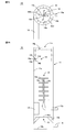
- FIG. 2A is a schematic top view of the gas absorption tower according to the present embodiment
- FIG. 2B is a schematic cross-sectional view of the gas absorption tower
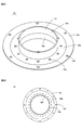
- FIG. 3A is a perspective view showing a liquid return member
- FIG. 3B is a top view showing the liquid return member.
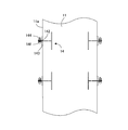
- It is a cross-sectional schematic diagram which shows the state which attached the liquid return member to the absorption tower main body.
- FIG. 1 is a schematic diagram showing an exhaust gas treatment system centered on a gas absorption tower according to the present embodiment.
- an exhaust gas treatment system according to the present embodiment a system that removes sulfur dioxide (SO 2 ) contained in exhaust gas discharged from an engine used in a ship is considered.
- SO 2 sulfur dioxide
- the present invention is not limited to this, and the exhaust gas treatment system according to the present embodiment can be applied to the treatment of various exhaust gases containing substances such as nitrogen oxides and sulfur oxides.
- the exhaust gas treatment system includes a gas absorption tower 10, an engine 20, a seawater pump unit 30 including a seawater pressurization pump and a seawater extraction pump, a drainage tank 40, and a filter unit for filtering wastewater. 50.
- the exhaust gas discharged from the engine 20 is introduced into the gas absorption tower 10.
- This exhaust gas contains 50 to 1500 ppm of sulfur dioxide (SO 2 ).
- SO 2 sulfur dioxide
- the seawater introduced into the gas absorption tower 10 through the seawater pump unit 30 is sprayed and brought into gas-liquid contact.
- the exhaust gas from which sulfur dioxide has been removed is exhausted from the upper part of the gas absorption tower 10 into the atmosphere.
- the seawater sprayed in the gas absorption tower 10 falls by its own weight along the inner wall surface of the gas absorption tower 10 and is stored in a storage section below the gas absorption tower 10.
- the stored seawater is drained into the drainage tank 40 via the seawater pump unit 30, then filtered by the filter unit 50 and drained to the ocean.
- FIG. 2A is a schematic top view of the gas absorption tower 10 according to the present embodiment
- FIG. 2B is a schematic cross-sectional view of the gas absorption tower 10.
- the gas absorption tower 10 sprays liquid in an absorption tower main body 11 composed of a cylindrical body whose central axis is directed in the vertical direction and a predetermined region in the vertical direction of the internal space of the absorption tower main body 11.
- the spray device 12, the gas supply device 13 that introduces gas into the absorption tower body 11 from a position below the region where the spray device 12 sprays the liquid, and the position above the region where the spray device 12 sprays the liquid are provided.
- the liquid return member 14 that protrudes in an annular shape from the inner wall surface of the absorption tower body 11 toward the central axis, and whose tip on the central axis side is folded back at least downward, and the baffle provided at a position lower than the spray device 12 15.
- the spray device 12 is connected to the seawater pump unit 30 shown in FIG. 1, and the gas supply device 13 is connected to the engine 20 shown in FIG.
- the absorption tower main body 11 includes a cylindrical peripheral wall portion 11a and a circular bottom wall portion 11b. All the peripheral wall portions 11a are configured to have the same diameter. The upper end part of the surrounding wall part 11a is opened, and the opening part 11c is formed.
- the absorption tower main body 11 has a cylindrical shape, the shape of the absorption tower main body 11 is not restricted to this, For example, a rectangular tube shape may be sufficient.
- the spray device 12 is installed on the central axis of the absorption tower body 11.
- the spray device 12 is inserted into the absorption tower main body 11 from the outside of the absorption tower main body 11 and is connected to a water supply pipe 12a extending to the center position of the absorption tower main body 11 and an insertion end of the water supply pipe 12a.
- a water conduit 12b extending over a predetermined region in the vertical direction of the internal space of the main body 11, a plurality of branch pipes 12c connected to the water conduit 12b, and a spray nozzle 12d provided at the tip of each branch pipe 12c , Including.
- the branch pipes 12c adjacent in the vertical direction cross each other so as to be orthogonal to each other.
- the spray nozzles 12d are provided on the same plane as the branch pipes 12c, and the ejection direction is perpendicular to the branch pipes 12c. With such a configuration, it is possible to spray the liquid uniformly inside the absorption tower body 11.
- the gas supply device 13 is provided so that the gas ejection direction is along the tangential direction of the peripheral wall portion 11 a of the absorption tower body 11. Therefore, the exhaust gas introduced from the gas supply device 13 is injected in the horizontal direction along the inner peripheral surface of the peripheral wall portion 11a.
- the liquid return member 14 includes a folded surface portion 14a that protrudes in an annular shape from the peripheral wall portion 11a of the absorber tower body 11 toward the central axis, a folded piece 14b that is folded downward from the tip on the central axis side of the folded surface portion 14a, and a folded surface. It has a liquid reservoir wall 14d protruding upward so as to form a liquid reservoir 14c from the tip of the surface portion 14a, and a through hole 14e for dropping the liquid accumulated in the liquid reservoir 14c.
- FIG. 3A is a perspective view showing the liquid return member 14, and FIG. 3B is a top view showing the liquid return member 14.
- the liquid return member 14 includes a cylindrical member 141 and a flange portion 142 that protrudes outward from the center position in the vertical direction of the cylindrical member 141.
- the flange portion 142 constitutes the folded surface portion 14a.
- a part of the cylindrical member 141 protruding downward from the flange portion 142 constitutes a bent piece 14b.
- a part of the cylindrical member 141 protruding above the flange portion 142 constitutes a liquid pool wall 14d.
- the outer diameter of the flange portion 142 is configured to be larger than the outer diameter of the peripheral wall portion 11a in the absorber tower body 11.
- the flange portion 142 has a plurality of through holes 14e on the inner peripheral side and a plurality of screw holes 14f on the outer peripheral side.
- FIG. 4 is a schematic cross-sectional view showing a state in which the liquid return member 14 is attached to the absorption tower body 11.
- the liquid return member 14 moves up and down the outer peripheral edge portion of the flange portion 142 protruding from the absorption tower body 11 with the central axis of the liquid return member 14 and the central axis of the absorption tower body 11 aligned.
- the absorber tower body 11 by being fastened with bolts 144 passed through the screw holes 14f.
- the flange part 142 will be in the state protruded horizontally from the surrounding wall part 11a of the absorption tower main body 11 toward the central axis.
- the region on the central axis side surrounded by the cylindrical member 141 of the liquid return member 14 attached to the absorption tower body 11 constitutes an opening 14g (see FIG. 2B).
- the opening 14g is configured to have an inner diameter of about 50 to 80% of the opening 11c of the absorber tower body 11. With this configuration, it is possible to suppress pressure loss caused by attaching the liquid return member 14 to the absorption tower body 11.
- the baffle 15 includes a disk part 15 a and leg parts 15 b that connect the disk part 15 a and the peripheral wall part 11 a of the absorption tower body 11. A gap for flowing droplets is formed between the outer peripheral portion of the disk portion 15a and the peripheral wall portion 11a of the absorber tower body 11.
- the baffle 15 divides the inside of the absorption tower main body 11 into a region where the liquid is sprayed by the spray device 12 and a region where the liquid for draining outside the absorption tower main body 11 is stored. Below the baffle 15, a drain pipe 16 for draining the liquid outside the absorption tower body 11 is provided below the baffle 15, a drain pipe 16 for draining the liquid outside the absorption tower body 11 is provided.
- exhaust gas treatment in the gas absorption tower 10 thus configured will be described.
- the exhaust gas discharged from the engine is introduced by the gas supply device 13 below the region where the spray device 12 sprays liquid.
- the exhaust gas rises in the absorption tower body 11 while circling along the peripheral wall portion 11a.
- seawater is introduced into the water conduit 12b through the water supply pipe 12a. And seawater is sprayed toward the surrounding wall part 11a of the absorption tower main body 11 from the spray nozzle 12d provided in the multistage branch pipe 12c.
- the exhaust gas swirling up in the absorption tower body 11 comes into gas-liquid contact with seawater sprayed from the spray nozzle 12d provided in the branch pipe 12c installed in each stage, and sulfur dioxide in the exhaust gas is absorbed and removed.
- the exhaust gas from which sulfur dioxide has been removed is exhausted into the atmosphere from an opening 11c provided in the upper part of the absorption tower body 11.
- the seawater that has become droplets is pressed against the peripheral wall 11a by the centrifugal force due to the swirling flow and falls by its own weight. However, part of the seawater rises through the inside of the absorption tower body 11 by the swirling upward flow.
- the central portion of the absorption tower body 11 has a gas flow velocity of 0 m / s or a value close to it, and the vicinity of the peripheral wall portion 11a has a higher gas flow velocity than the central portion, so seawater rises along the peripheral wall portion 11a by centrifugal force. To do. Seawater rising along the peripheral wall portion 11a is prevented from rising by the lowermost liquid return member 14, and stays on the lower surface of the flange portion 142 and the periphery of the folded piece 14b. When the staying liquid exceeds a certain size, it becomes droplets and falls by its own weight.
- the vicinity of the peripheral wall portion 11a of the absorption tower body 11 has a higher gas flow rate than the central portion of the absorption tower body 11, and therefore, if the through hole 14e is provided in the vicinity of the peripheral wall portion 11a, it penetrates under the influence of the upward flow. There may be a situation in which the droplet does not fall from the hole 14e. Therefore, by providing the through hole 14e at a position where the gas flow rate is slow compared to the vicinity of the peripheral wall portion 11a and away from the peripheral wall portion 11a, the influence of the upward flow can be weakened to drop the droplet from the through hole 14e. .
- the liquid return member 14 Since the liquid return member 14 is provided in a plurality of stages in the vertical direction, the rise of seawater by the liquid return member 14 is prevented a plurality of times. Therefore, the situation where seawater rises and flows out from the opening 11c of the absorption tower body 11 can be effectively prevented.
- the liquid return member 14 has a shape protruding in an annular shape from the peripheral wall portion 11a of the absorption tower main body 11 toward the central axis. Since the opening 14g is formed, pressure loss due to the attachment of the liquid return member 14 can be reduced. Moreover, clogging does not occur due to the liquid return member 14, and complicated maintenance is unnecessary.
- the dropped liquid droplet is stopped by a baffle 15 installed below the absorption tower main body 11, and then connected to the bottom wall 11b of the absorption tower main body 11 and its surroundings by connecting the baffle 15 and the peripheral wall 11a. It stores in the storage part comprised with the surrounding wall part 11a. The stored liquid is drained out of the absorption tower body 11 through the drain pipe 16.
- the liquid return provided above the region where the spray device 12 inside the absorption tower body 11 sprays liquid (for example, seawater). Since the member 14 prevents the liquid from rising, it is possible to effectively prevent the liquid from rising and flowing out from the opening at the upper end of the absorption tower body. Thereby, it becomes possible to prevent the outflow of the liquid while suppressing the installation space and suppressing the pressure loss.
- liquid for example, seawater
Landscapes
- Engineering & Computer Science (AREA)
- Chemical & Material Sciences (AREA)
- Health & Medical Sciences (AREA)
- Biomedical Technology (AREA)
- Environmental & Geological Engineering (AREA)
- Analytical Chemistry (AREA)
- General Chemical & Material Sciences (AREA)
- Oil, Petroleum & Natural Gas (AREA)
- Chemical Kinetics & Catalysis (AREA)
- Treating Waste Gases (AREA)
- Gas Separation By Absorption (AREA)
Abstract
L'objet de cette invention est de pourvoir à une tour d'absorption de gaz destinée à être installée dans un espace qui est restreint et qui empêche le débordement de liquide tout en limitant la perte de pression. La tour d'absorption de gaz (10) selon l'invention qui absorbe le gaz par mise en contact dudit gaz avec un liquide comprend : un corps de tour d'absorption principal (11) obtenu à partir d'un cylindre dont l'axe central est orienté dans le sens vertical ; un dispositif de pulvérisation (12) qui pulvérise le liquide vers une région spécifique dans le sens vertical de l'espace interne dudit corps de tour d'absorption principal (11) ; un dispositif d'alimentation en gaz (13) qui introduit le gaz dans le corps de tour d'absorption principal (11) à partir d'une position située plus bas que la région dans laquelle le dispositif de pulvérisation (12) pulvérise le liquide ; et un élément de recyclage de liquide (14) occupant une position située plus haut que la région dans laquelle le dispositif de pulvérisation (12) pulvérise le liquide, et qui forme une protubérance sur la surface de paroi intérieure du corps de tour d'absorption principal (11) en direction de l'axe central selon une forme circulaire, et dont le bord côté axe central est au moins replié vers le bas.
Applications Claiming Priority (2)
| Application Number | Priority Date | Filing Date | Title |
|---|---|---|---|
| JP2012-160809 | 2012-07-19 | ||
| JP2012160809 | 2012-07-19 |
Publications (1)
| Publication Number | Publication Date |
|---|---|
| WO2014014002A1 true WO2014014002A1 (fr) | 2014-01-23 |
Family
ID=49948828
Family Applications (1)
| Application Number | Title | Priority Date | Filing Date |
|---|---|---|---|
| PCT/JP2013/069353 Ceased WO2014014002A1 (fr) | 2012-07-19 | 2013-07-17 | Tour d'absorption de gaz |
Country Status (1)
| Country | Link |
|---|---|
| WO (1) | WO2014014002A1 (fr) |
Cited By (7)
| Publication number | Priority date | Publication date | Assignee | Title |
|---|---|---|---|---|
| JPWO2015056562A1 (ja) * | 2013-10-17 | 2017-03-09 | 富士電機株式会社 | ガス吸収塔、ガス吸収塔の製造方法及び船舶 |
| JP2017056385A (ja) * | 2015-09-14 | 2017-03-23 | 富士電機株式会社 | 排ガス処理装置および排ガス処理装置のメンテナンス方法 |
| JP2017087193A (ja) * | 2015-11-17 | 2017-05-25 | 富士電機株式会社 | 排ガス処理装置および幹管の分割体を吸収塔から取り出す方法 |
| WO2017159102A1 (fr) * | 2016-03-16 | 2017-09-21 | 富士電機株式会社 | Dispositif de traitement de gaz d'échappement |
| JP2020525273A (ja) * | 2017-08-24 | 2020-08-27 | パンアジア カンパニー リミテッド | 排気ガス処理システム |
| WO2021176880A1 (fr) * | 2020-03-06 | 2021-09-10 | 富士電機株式会社 | Dispositif de traitement de gaz d'échappement et unité de décharge de liquide |
| US12030012B2 (en) | 2021-05-18 | 2024-07-09 | Fuji Electric Co., Ltd. | Scrubber apparatus for geothermal power generation |
Citations (4)
| Publication number | Priority date | Publication date | Assignee | Title |
|---|---|---|---|---|
| JPS577528B2 (fr) * | 1975-11-04 | 1982-02-10 | ||
| JPS6320920U (fr) * | 1986-07-21 | 1988-02-12 | ||
| JPH11239715A (ja) * | 1998-02-24 | 1999-09-07 | Ishikawajima Harima Heavy Ind Co Ltd | 脱硫煙突とその据付方法 |
| JP2000084352A (ja) * | 1998-09-09 | 2000-03-28 | Ishikawajima Harima Heavy Ind Co Ltd | 煙突一体型排煙脱硫装置 |
-
2013
- 2013-07-17 WO PCT/JP2013/069353 patent/WO2014014002A1/fr not_active Ceased
Patent Citations (4)
| Publication number | Priority date | Publication date | Assignee | Title |
|---|---|---|---|---|
| JPS577528B2 (fr) * | 1975-11-04 | 1982-02-10 | ||
| JPS6320920U (fr) * | 1986-07-21 | 1988-02-12 | ||
| JPH11239715A (ja) * | 1998-02-24 | 1999-09-07 | Ishikawajima Harima Heavy Ind Co Ltd | 脱硫煙突とその据付方法 |
| JP2000084352A (ja) * | 1998-09-09 | 2000-03-28 | Ishikawajima Harima Heavy Ind Co Ltd | 煙突一体型排煙脱硫装置 |
Cited By (15)
| Publication number | Priority date | Publication date | Assignee | Title |
|---|---|---|---|---|
| JPWO2015056562A1 (ja) * | 2013-10-17 | 2017-03-09 | 富士電機株式会社 | ガス吸収塔、ガス吸収塔の製造方法及び船舶 |
| JP2017056385A (ja) * | 2015-09-14 | 2017-03-23 | 富士電機株式会社 | 排ガス処理装置および排ガス処理装置のメンテナンス方法 |
| WO2017047292A1 (fr) * | 2015-09-14 | 2017-03-23 | 富士電機株式会社 | Dispositif de traitement de gaz d'échappement et procédé de maintenance pour le dispositif de traitement de gaz d'échappement |
| JP2017087193A (ja) * | 2015-11-17 | 2017-05-25 | 富士電機株式会社 | 排ガス処理装置および幹管の分割体を吸収塔から取り出す方法 |
| WO2017086024A1 (fr) * | 2015-11-17 | 2017-05-26 | 富士電機株式会社 | Dispositif et procédé de traitement de gaz d'échappement pour extraction de segment de tuyau de tige d'une colonne d'absorption |
| CN106999843A (zh) * | 2015-11-17 | 2017-08-01 | 富士电机株式会社 | 废气处理装置及从吸收塔取出主管的分割体的方法 |
| WO2017159102A1 (fr) * | 2016-03-16 | 2017-09-21 | 富士電機株式会社 | Dispositif de traitement de gaz d'échappement |
| JP2020525273A (ja) * | 2017-08-24 | 2020-08-27 | パンアジア カンパニー リミテッド | 排気ガス処理システム |
| JP2022058368A (ja) * | 2017-08-24 | 2022-04-12 | パンアジア カンパニー リミテッド | 排気ガス処理システム |
| JP7282151B2 (ja) | 2017-08-24 | 2023-05-26 | パンアジア カンパニー リミテッド | 排気ガス処理システム |
| WO2021176880A1 (fr) * | 2020-03-06 | 2021-09-10 | 富士電機株式会社 | Dispositif de traitement de gaz d'échappement et unité de décharge de liquide |
| JPWO2021176880A1 (fr) * | 2020-03-06 | 2021-09-10 | ||
| CN114206476A (zh) * | 2020-03-06 | 2022-03-18 | 富士电机株式会社 | 废气处理装置和液体排出单元 |
| JP7323052B2 (ja) | 2020-03-06 | 2023-08-08 | 富士電機株式会社 | 排ガス処理装置および液体排出ユニット |
| US12030012B2 (en) | 2021-05-18 | 2024-07-09 | Fuji Electric Co., Ltd. | Scrubber apparatus for geothermal power generation |
Similar Documents
| Publication | Publication Date | Title |
|---|---|---|
| JP5998915B2 (ja) | 排ガス処理装置 | |
| JP5958645B2 (ja) | 排ガス処理装置及び船舶 | |
| KR101874338B1 (ko) | 복합형 악취 제거장치 | |
| JP5744223B2 (ja) | 湿式スクラバおよびプロセスガスを浄化する方法 | |
| KR101166484B1 (ko) | 싸이클론식 세정탑 | |
| KR101331002B1 (ko) | 선박용 배기가스 세정장치 | |
| ES2765516T3 (es) | Un conjunto de un lecho de fibras para un eliminador de neblina de lecho de fibras | |
| WO2017159099A1 (fr) | Dispositif de traitement de gaz d'échappement | |
| CN104136096B (zh) | 烟气净化装置 | |
| CN204170594U (zh) | 胶粉改性沥青生产喷淋水洗塔 | |
| JPH11151425A (ja) | 煙突一体型排煙脱硫装置 | |
| CN105944547B (zh) | 一种烟气超低排放吸收塔装置及应用 | |
| JP6559873B1 (ja) | 気液混合装置、および気液混合装置を備える排ガス脱硫装置 | |
| CN107803089A (zh) | 一种除沫器 | |
| CN204233963U (zh) | 动力波废气吸收塔 | |
| JP2014163344A (ja) | 船舶用ミスト除去装置 | |
| CN203678201U (zh) | 多级隔板式脱硫除尘器 | |
| WO2020095886A1 (fr) | Dispositif d'évacuation de drainage | |
| JP2016068029A (ja) | 気液接触装置 | |
| KR101948275B1 (ko) | 연도 가스 정화 장치 | |
| CN202270454U (zh) | 一种烟气脱硫除尘器 | |
| JP2016068030A (ja) | 噴霧ノズル及びその噴霧ノズルを備えた気液接触装置 | |
| CN209362111U (zh) | 废气雾化吸附净化处理系统 | |
| RU2166980C2 (ru) | Массообменная установка | |
| JP2007248015A (ja) | スタックレイン防止用の排突構造 |
Legal Events
| Date | Code | Title | Description |
|---|---|---|---|
| 121 | Ep: the epo has been informed by wipo that ep was designated in this application |
Ref document number: 13819769 Country of ref document: EP Kind code of ref document: A1 |
|
| NENP | Non-entry into the national phase |
Ref country code: DE |
|
| 122 | Ep: pct application non-entry in european phase |
Ref document number: 13819769 Country of ref document: EP Kind code of ref document: A1 |
|
| NENP | Non-entry into the national phase |
Ref country code: JP |