WO2014016033A1 - A cooking device comprising a cooling fan - Google Patents
A cooking device comprising a cooling fan Download PDFInfo
- Publication number
- WO2014016033A1 WO2014016033A1 PCT/EP2013/061873 EP2013061873W WO2014016033A1 WO 2014016033 A1 WO2014016033 A1 WO 2014016033A1 EP 2013061873 W EP2013061873 W EP 2013061873W WO 2014016033 A1 WO2014016033 A1 WO 2014016033A1
- Authority
- WO
- WIPO (PCT)
- Prior art keywords
- control card
- fan
- cooking device
- cooktop
- oven
- Prior art date
- Legal status (The legal status is an assumption and is not a legal conclusion. Google has not performed a legal analysis and makes no representation as to the accuracy of the status listed.)
- Ceased
Links
Images


Classifications
-
- F—MECHANICAL ENGINEERING; LIGHTING; HEATING; WEAPONS; BLASTING
- F24—HEATING; RANGES; VENTILATING
- F24C—DOMESTIC STOVES OR RANGES ; DETAILS OF DOMESTIC STOVES OR RANGES, OF GENERAL APPLICATION
- F24C15/00—Details
- F24C15/006—Arrangements for circulation of cooling air
Definitions
- the present invention relates to a cooking device wherein the electronic control card thereof is provided to be cooled by means of a fan.
- the electronic control cards that are used in cooking devices and of critical importance in terms of safety and functionality must be protected against high temperatures.
- the control cards are generally cooled by means of a fan.
- the control card In the cooking devices, especially in the ovens, the control card is generally placed behind the front panel. By sucking air by means of a fan from the gap behind the front panel, wherein the control card is situated, the control card is cooled.
- the vicinity of the front panel heats up excessively due to various causes. For example, when grilling function is performed by keeping the oven door open, the hot air rising from the oven cavity affects the front panel.
- the resistance inlets of the electric heaters in the oven are generally situated at the rear side of the oven, the temperature of these regions are lower and the temperature of the heaters increases towards the front.
- burners having a large diameter and generating much heat are generally located at the front of the cooktop, close to the control panel.
- heat produced by electronic elements in the control card while operating adds up to the heat produced at the oven and cooktop parts of the cooking device and it becomes difficult to cool the control card placed behind the front panel.
- pyrolytic ovens with self-cleaning function wherein very high temperatures such as 500 °C are applied, the control card cannot be sufficiently cooled and may be damaged.
- an oven wherein the air sucked from the space in which the electronic control card situated behind the front panel by means of a fan is discharged through the outlet opening that opens to the outside environment.
- the fan disclosed in the above-mentioned patent applications is used for discharging the humid air in the oven cavity and provides the indirect cooling of the control card.
- the aim of the present invention is the realization of a cooking device wherein the control card thereof is efficiently cooled and protected against high temperatures.
- the cooking device realized in order to attain the aim of the present invention, explicated in the first claim and the respective claims thereof comprises a cooktop, an oven underlying the cooktop, a compartment located under the cooktop and behind the front panel, a control card providing the electronic control and a fan cooling the control card, and the control card is moved away from the front panel to be mounted to the body side wall and the air sucked from the outside environment by means of a fan located on the rear wall is sent directly onto the control card through an air duct extending between the fan and the control card in the compartment, thus the control card is efficiently cooled.
- control card and the fan are placed in the body on the side wall close to the corner of the rear wall, and it is provided that the length of the air duct extending diagonally between the fan and the control card is at a minimum value and that the air sucked from the outside reach the control card before getting warm.
- a hanger bracket is mounted to the side wall of the cooking device body and the control card is mounted to the hanger bracket.
- a lower plate formed by bending the bottom side of the hanger bracket carries the control card and decreases the effect of the heat rising from the oven on the control card.
- a horizontal upper plate mounted to the top side of the control card decreases the effect of the heat in the cooktop on the control card.
- the hanger bracket carrying the control card, the lower plate and the upper plate fixed to the control card are produced from metal material, and serve as a heat sink for the control card.
- control card is protected against high heat dissipated from the cooktop at the top and the oven at the bottom, efficiently cooled by means of the fan and the air duct, and the lifespan of the electronic elements on the control card is prolonged.
- Figure 1 – is the perspective view of a cooking device.
- Figure 2 – is the sideways schematic view of a cooking device.
- Figure 3 – is the top schematic view of a cooking device.
- Figure 4 – is the schematic view of the electronic card, the protective elements and the cooling fan located in a cooking device.
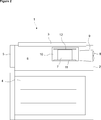
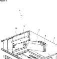
- Figure 5 — is the partial view of a cooking device.
- the cooking device (1) comprises a body (2), a cooktop (3) located at the top side thereof, having gas burners and/or electric heaters thereon, an oven (4) underlying the cooktop (3), a front panel (5) situated at the front of the body (2) and having buttons and displays thereon, a compartment (6) situated between the cooktop (3) and the oven (4), a control card (7) having electronic elements thereon, that provide the controlling of the oven (4) and the cooktop (3), and a fan (8) providing the cooling of the control card (7).
- the cooking device (1) of the present invention comprises - the control card (7) placed to the side wall of the body (2), - the fan (8) placed to the rear wall of the body (2) and - an air duct (9) that extends in the compartment (6), between the fan (8) and the control card (7) and that guides the air sucked from the outer environment by the fan (8) directly onto the control card (7) without circulating it in the compartment (6).
- the control card (7) is placed onto the side wall of the body (2), hence moved away from the front panel (5) and operates in an environment with a relatively lower temperature than that of the front panel (5).
- the control card (7) is protected against high temperatures affecting the front panel (5) and heat rising from the oven (4) towards the front panel (5), for example when the oven (4) door is opened at the end of the cooking process or when grilling function is performed with the oven (4) door being kept open.
- the air duct (9) that guides the air sucked from the outer environment by the fan (8) directly onto the control card (7) without circulating it in the compartment (6), provides the efficient cooling of the control card (7).
- control card (7) and the fan (8) are placed close to the corner where the side wall and the rear wall of the body (2) join, and the air duct (9) extends diagonally in the compartment (6), between the fan (8) and the control card (7) ( Figure 3, Figure 5).
- the fan (8) and the control card (7) are placed in the compartment (6) so as to face each other and at a position closest to each other, thus the length of the air duct (9) in the compartment (6) is minimized.
- the air sucked from the outer environment by the fan (8) passes through the air duct (9) with the minimum length in the compartment (6) without getting warm to reach directly the control card (7).
- the cooking device (1) comprises a hanger bracket (10) mounted to the inner surface of the body (2) side wall, whereon the control card (7) is mounted, providing the control card (7) to be placed to the body (2) side wall by being hung and to be easily mounted/dismounted ( Figure 4, Figure 5).
- the cooking device (1) comprises a lower plate (11) that is formed by bending the bottom side of the hanger bracket (10) in form of an L, that extends horizontally between the control card (7) and the oven (4) towards the inside of the compartment (6), that carries the control card (7) and that reduces the effect of the high heat rising from the oven (4) to the control card (7) by creating a barrier between the control card (7) and the oven (4).
- the cooking device (1) comprises an upper plate (12) that is mounted to the top side of the control card (7), that extends horizontally between the cooktop (3) and the control card (7) towards the inside of the compartment (6) and that reduces the effect of the high heat dissipating from the cooktop (3) to the control card (7) by creating a barrier between the control card (7) and the cooktop (3) ( Figure 4, Figure 5).
- the upper plate (12) serves as a handle by being fixed to the control card (7) and facilitates the process of mounting the control card (7) to the hanger bracket (10), hence to the body (2) side wall.
- the upper plate (12), the hanger bracket (10) and the lower plate (11) are produced from metal material, for example from sheet steel. Heat generated by the electronic elements in the control card (7) is transferred to the upper plate (12) and the hanger bracket (10), thus to the lower plate (11) by means of conduction. Being cooled by the ambient air coming from the air duct (9), the upper plate (12), the hanger bracket (10) and the lower plate (11) function as a heat sink for the control card (7).
- the air received from the outer environment by means of the fan (8) is guided directly onto the control card (7) through the air duct (9), thus provides the efficient cooling of the control card (7).
- the electronic elements in the control card (7) are protected against high heat and prevented from being damaged.
Landscapes
- Engineering & Computer Science (AREA)
- Chemical & Material Sciences (AREA)
- Combustion & Propulsion (AREA)
- Mechanical Engineering (AREA)
- General Engineering & Computer Science (AREA)
- Electric Ovens (AREA)
- Electric Stoves And Ranges (AREA)
Priority Applications (2)
| Application Number | Priority Date | Filing Date | Title |
|---|---|---|---|
| EP13727620.0A EP2877785B1 (en) | 2012-07-27 | 2013-06-10 | A cooking device comprising a cooling fan |
| ES13727620.0T ES2604879T3 (es) | 2012-07-27 | 2013-06-10 | Un dispositivo de cocción que comprende un ventilador de enfriamiento |
Applications Claiming Priority (2)
| Application Number | Priority Date | Filing Date | Title |
|---|---|---|---|
| TR201208811 | 2012-07-27 | ||
| TRA2012/08811 | 2012-07-27 |
Publications (1)
| Publication Number | Publication Date |
|---|---|
| WO2014016033A1 true WO2014016033A1 (en) | 2014-01-30 |
Family
ID=48577768
Family Applications (1)
| Application Number | Title | Priority Date | Filing Date |
|---|---|---|---|
| PCT/EP2013/061873 Ceased WO2014016033A1 (en) | 2012-07-27 | 2013-06-10 | A cooking device comprising a cooling fan |
Country Status (4)
| Country | Link |
|---|---|
| EP (1) | EP2877785B1 (pl) |
| ES (1) | ES2604879T3 (pl) |
| PL (1) | PL2877785T3 (pl) |
| WO (1) | WO2014016033A1 (pl) |
Cited By (2)
| Publication number | Priority date | Publication date | Assignee | Title |
|---|---|---|---|---|
| WO2019048977A1 (de) * | 2017-09-07 | 2019-03-14 | BSH Hausgeräte GmbH | Kochfeldvorrichtung |
| US11428417B2 (en) | 2019-06-27 | 2022-08-30 | Bsh Home Appliance Corporation | Home cooking appliance having a cooling fan air guide |
Citations (7)
| Publication number | Priority date | Publication date | Assignee | Title |
|---|---|---|---|---|
| JP2002299026A (ja) * | 2001-03-30 | 2002-10-11 | Hitachi Hometec Ltd | 誘導加熱調理器 |
| EP1457740A1 (en) | 2003-03-12 | 2004-09-15 | Whirlpool Corporation | Method of operating a domestic oven and cooking oven having a cooling fan |
| JP2007294474A (ja) * | 2007-07-03 | 2007-11-08 | Mitsubishi Electric Corp | 誘導加熱調理器 |
| WO2011080097A2 (en) | 2009-12-31 | 2011-07-07 | Arcelik Anonim Sirketi | Oven with a ventilating device |
| JP2012094423A (ja) * | 2010-10-28 | 2012-05-17 | Mitsubishi Electric Corp | 誘導加熱調理器 |
| JP2012104261A (ja) * | 2010-11-08 | 2012-05-31 | Mitsubishi Electric Corp | 誘導加熱調理器 |
| US20120152933A1 (en) * | 2010-03-17 | 2012-06-21 | Panasonic Corporation | Induction cooking appliance |
Family Cites Families (2)
| Publication number | Priority date | Publication date | Assignee | Title |
|---|---|---|---|---|
| JP2001324152A (ja) * | 2000-05-15 | 2001-11-22 | Rinnai Corp | 加熱調理器 |
| CN102771523B (zh) * | 2008-01-28 | 2015-04-22 | 杜克制造公司 | 对流式炉 |
-
2013
- 2013-06-10 WO PCT/EP2013/061873 patent/WO2014016033A1/en not_active Ceased
- 2013-06-10 PL PL13727620T patent/PL2877785T3/pl unknown
- 2013-06-10 EP EP13727620.0A patent/EP2877785B1/en not_active Not-in-force
- 2013-06-10 ES ES13727620.0T patent/ES2604879T3/es active Active
Patent Citations (7)
| Publication number | Priority date | Publication date | Assignee | Title |
|---|---|---|---|---|
| JP2002299026A (ja) * | 2001-03-30 | 2002-10-11 | Hitachi Hometec Ltd | 誘導加熱調理器 |
| EP1457740A1 (en) | 2003-03-12 | 2004-09-15 | Whirlpool Corporation | Method of operating a domestic oven and cooking oven having a cooling fan |
| JP2007294474A (ja) * | 2007-07-03 | 2007-11-08 | Mitsubishi Electric Corp | 誘導加熱調理器 |
| WO2011080097A2 (en) | 2009-12-31 | 2011-07-07 | Arcelik Anonim Sirketi | Oven with a ventilating device |
| US20120152933A1 (en) * | 2010-03-17 | 2012-06-21 | Panasonic Corporation | Induction cooking appliance |
| JP2012094423A (ja) * | 2010-10-28 | 2012-05-17 | Mitsubishi Electric Corp | 誘導加熱調理器 |
| JP2012104261A (ja) * | 2010-11-08 | 2012-05-31 | Mitsubishi Electric Corp | 誘導加熱調理器 |
Cited By (2)
| Publication number | Priority date | Publication date | Assignee | Title |
|---|---|---|---|---|
| WO2019048977A1 (de) * | 2017-09-07 | 2019-03-14 | BSH Hausgeräte GmbH | Kochfeldvorrichtung |
| US11428417B2 (en) | 2019-06-27 | 2022-08-30 | Bsh Home Appliance Corporation | Home cooking appliance having a cooling fan air guide |
Also Published As
| Publication number | Publication date |
|---|---|
| EP2877785A1 (en) | 2015-06-03 |
| PL2877785T3 (pl) | 2017-02-28 |
| ES2604879T3 (es) | 2017-03-09 |
| EP2877785B1 (en) | 2016-09-07 |
Similar Documents
| Publication | Publication Date | Title |
|---|---|---|
| US10523851B2 (en) | Camera assembly for an oven appliance | |
| US8333183B2 (en) | Cooking range including an air circulation mechanism | |
| US6172338B1 (en) | Cooling system for a cooking appliance | |
| EP3134684B1 (en) | A cooking oven with an oven cavity and an oven door | |
| US10006639B2 (en) | Appliance side panel with air channel | |
| EP2658340A1 (en) | Induction range including an air layer for improving heat resistance and shock resistance | |
| US20120285437A1 (en) | Door of electric oven | |
| CN111012208A (zh) | 烹饪设备 | |
| WO2011028734A1 (en) | Method and apparatus for cooling a user interface and/or door of a cooking device | |
| KR20210106290A (ko) | 조리기기 및 그 제어방법 | |
| EP2798277B1 (en) | An oven comprising an exhaust duct | |
| JP5092566B2 (ja) | 誘導加熱調理器 | |
| EP2877785B1 (en) | A cooking device comprising a cooling fan | |
| EP4328491A1 (en) | Cooking appliance | |
| JP2009213684A (ja) | 加熱調理器 | |
| US9335055B2 (en) | Oven appliance | |
| EP1818620B1 (en) | Oven having a pull out door with integral heating element and cooking grids | |
| US11009235B2 (en) | Domestic kitchen appliance with sidewall cooling | |
| EP1819966A2 (en) | Oven with improved arrangement of the internal elements | |
| JP4423120B2 (ja) | 加熱調理器 | |
| KR101531062B1 (ko) | 덕트 유니트를 포함한 오븐 레인지 | |
| KR101531061B1 (ko) | 열 차단 수단을 구비한 오븐 레인지 | |
| EP1972856B1 (en) | Cooking appliance | |
| WO2015165530A1 (en) | Oven with ventilation unit and heat protective shield | |
| KR101079402B1 (ko) | 과열방지 오븐도어 |
Legal Events
| Date | Code | Title | Description |
|---|---|---|---|
| 121 | Ep: the epo has been informed by wipo that ep was designated in this application |
Ref document number: 13727620 Country of ref document: EP Kind code of ref document: A1 |
|
| WWE | Wipo information: entry into national phase |
Ref document number: 2014/11843 Country of ref document: TR |
|
| REEP | Request for entry into the european phase |
Ref document number: 2013727620 Country of ref document: EP |
|
| WWE | Wipo information: entry into national phase |
Ref document number: 2013727620 Country of ref document: EP |
|
| NENP | Non-entry into the national phase |
Ref country code: DE |