WO2014016899A1 - Dispositif de commande de puissance et procédé de commande de puissance - Google Patents
Dispositif de commande de puissance et procédé de commande de puissance Download PDFInfo
- Publication number
- WO2014016899A1 WO2014016899A1 PCT/JP2012/068675 JP2012068675W WO2014016899A1 WO 2014016899 A1 WO2014016899 A1 WO 2014016899A1 JP 2012068675 W JP2012068675 W JP 2012068675W WO 2014016899 A1 WO2014016899 A1 WO 2014016899A1
- Authority
- WO
- WIPO (PCT)
- Prior art keywords
- power
- value
- control
- target
- integrated
- Prior art date
- Legal status (The legal status is an assumption and is not a legal conclusion. Google has not performed a legal analysis and makes no representation as to the accuracy of the status listed.)
- Ceased
Links
Images



Classifications
-
- G—PHYSICS
- G05—CONTROLLING; REGULATING
- G05D—SYSTEMS FOR CONTROLLING OR REGULATING NON-ELECTRIC VARIABLES
- G05D23/00—Control of temperature
- G05D23/19—Control of temperature characterised by the use of electric means
- G05D23/1919—Control of temperature characterised by the use of electric means characterised by the type of controller
Definitions
- the present invention relates to a power control apparatus and a power control method for controlling power supplied to a plurality of loads in a time-sharing manner.
- Patent Literatures 1 and 2 below disclose power control devices that supply power proportional to an operation signal (target value) output from a PID controller to a load such as a heater.
- control for switching on / off of power supplied to a load is performed every time corresponding to an integral multiple of a half cycle of a power supply waveform (hereinafter referred to as “unit time”).
- unit time an integral multiple of a half cycle of a power supply waveform
- the load The power supply to is turned on.
- the power supply feedback signal G is set to a value of “0” when the power supply to the load is turned off, and set to a value of “1” when the power supply to the load is turned on.
- the value when the power supply to the load is turned on is set to “1” according to the power supply voltage so that it is not affected by the power supply voltage fluctuation.
- Patent Documents 3 to 5 when power supplied to a plurality of loads is simultaneously controlled in a time-sharing manner, the number of loads that are simultaneously supplied with power in each unit time is suppressed.
- the total amount of power supplied to all loads in time is set so as not to exceed a preset power upper limit value (for example, an upper limit value of power set based on various conditions of the power supply equipment and the apparatus).
- peak power suppression control such control is referred to as “peak power suppression control”.
- the total amount of power supplied to all loads in each unit time is “0” for the load for which power supply is turned off, and “1” for the load for which power supply is turned on.
- the total value of the power supply amount to the load calculated based on the preset rated power of each load is prevented from exceeding the upper limit power.
- Japanese Patent No. 3022051 Japanese Patent No. 3675951 Japanese Patent No. 3794574 Japanese Patent No. 4529153 JP 2011-205731 A
- the conventional power control apparatus that performs peak power suppression control is configured as described above, when the power supply to the load is turned on, the power supply of “1” from the load factor X corresponding to the target value is performed. Although the feedback signal G is subtracted, the value of the power supply feedback signal G is a constant value that does not reflect fluctuations in power consumption due to fluctuations in power supply voltage or load fluctuations. For this reason, when the fluctuation
- the rated power or rated power of the load for which the power supply amount for the load for which power supply is turned on is set in advance without considering the fluctuation of power consumption due to the fluctuation of power supply voltage or load fluctuation. It is calculated as “1” which is a normalized value. For this reason, when the fluctuation
- the power control apparatus that performs peak power suppression control
- power on / off is determined in order from the load having the largest integrated value ⁇ Y among the integrated values ⁇ Y of a plurality of loads.
- the output value is limited. Therefore, the integrated value Y always becomes a positive value, and the integrated value ⁇ Y continues to increase. The upper limit will be reached.
- the integrated values ⁇ Y of a plurality of control objects reach a numerical upper limit value, it becomes impossible to determine on / off of power in order from a load with a large integrated value ⁇ Y.
- the ratio between the target value of power and the amount of supplied power may be different for each load.
- the present invention has been made in order to solve the above-described problems. Even when a power supply voltage fluctuation or a load fluctuation occurs, a fluctuation in power supplied to the load can be suppressed, and a total load for all loads can be reduced. It is an object of the present invention to obtain a power control apparatus and a power control method for performing peak power suppression control that can suppress the amount of supplied power within a power upper limit value. Another object of the present invention is to provide a power control apparatus that performs peak power suppression control that can prevent a situation where the ratio between the target value of power and the amount of supplied power differs for each load.
- the power control apparatus includes a plurality of switching control means for switching on / off of power supplied to each control target at predetermined unit times, and target power that is a target value of power supplied to each control target.
- a target power value calculating means for calculating a value, a power measuring means for measuring a power measurement value that is a value of power supplied to each control object, and when power is supplied to each control object
- a power estimation unit that estimates a power value when power is supplied to the control target during a unit time of the next control cycle from the power measurement value measured by the power measurement unit, and a target power value for each control target
- the power difference integrated value is calculated by repeating the addition of the target power value calculated by the calculation means and the subtraction of the power measurement value measured by the power measurement means for each control cycle, and the power up to the previous control cycle.
- An intermediate integrated power value calculating means for calculating the latest intermediate integrated power value by adding the integrated value and the target power value of the next control cycle calculated by the target power value calculating means; and the power control means,
- the intermediate integrated power value of the control object is larger than a predetermined threshold in order from the control object having the large intermediate integrated power value calculated by the intermediate integrated power value calculation means, and the control object
- the power value of the control target estimated by the power estimation means and the power value estimated by the power estimation means, and supplying power in the next control cycle If the power supply condition that the sum of the power values of the other control targets that have been determined does not become higher than the predetermined power upper limit value is satisfied, the switching control means of the control target is controlled to be in the on state. If the power supply condition is not satisfied, the process for controlling the switching control means to be turned off is repeatedly performed, and the switching control means in the next control cycle is controlled for all control objects. It is a thing.
- the power control apparatus provides, for each control target, the power difference integrated value calculated by the intermediate integrated power value calculating means until the previous control cycle and the target power value calculated by the target power value calculating means.
- the latest integrated value for calculating the adjustment coefficient is calculated by adding, and if the sum of the integrated values for calculating the adjustment coefficient of each control object is larger than the power upper limit value, the total sum of the adjusted coefficient calculating integrated values and the power upper limit value Is calculated as a power value adjustment coefficient, and if the sum of the adjustment coefficient calculation integrated values is smaller than the power upper limit value, the power value adjustment coefficient is set to 1, and the power value is set for each control target. Adjustment means for adjusting the target power value or the measured power value using an adjustment coefficient is provided.
- the intermediate integrated power value calculation means adjusts the power measurement value by the adjustment means, for each control object, from the intermediate integrated power value calculated in the previous control cycle.
- the power difference integrated value up to the previous control cycle is calculated by subtracting the power measurement value of the previous control cycle adjusted with the power value adjustment coefficient, and the power difference integrated value and the next calculated by the target power value calculating means are calculated.
- the power estimation unit estimates the The sum of the power value of the control target and the power value estimated by the power estimation means and the power value of another control target that has been determined to supply power in the next control cycle is a predetermined power. If the power supply condition that does not become higher than the upper limit value is satisfied, the switching control means to be controlled is controlled to be in the on state, and if the power supply condition is not satisfied, the switching control means to be controlled is controlled to be in the off state. The processing is repeated to control the switching control means on / off in the next control cycle for all control objects.
- the intermediate integrated power value calculating unit calculates from the intermediate integrated power value calculated in the previous control cycle for each control target. , Subtract the power measurement value of the previous control cycle, calculate the power difference integrated value up to the previous control cycle, and adjust the power value adjustment coefficient to the target power value of the next control cycle and the power difference integrated value
- the latest intermediate integrated power value is calculated, and the power control means sequentially starts from the control object having the largest intermediate integrated power value calculated by the intermediate integrated power value calculation means.
- the power value of the control target estimated by the power estimation unit and the power estimation A power supply condition that is the power value estimated by the stage and that the sum of the power value of the other control objects that are determined to supply power in the next control cycle does not become higher than a predetermined power upper limit value. If satisfied, the control target switching control means is controlled to be in the on state, and if the power supply condition is not satisfied, the control target switching control means is turned off and the control is repeatedly performed. The switching control means is controlled to be turned on / off in the next control cycle.
- the target power value calculation means inputs the output target value of the control target from another device for each control target, and sets the output target value to a predetermined reference power value. Multiplication is performed, and the multiplication result is set to the target power value of the control target.
- the target power value calculation means inputs a target value normalized from another device as a target value of power supplied to each control target, and the normalized target The value is set to the target power value, and the power measurement means converts the power measurement value of each control target into a normalized value with the reference power value and outputs the normalized value.
- the power control method includes a plurality of switching processing steps in which a plurality of switching control means switches on / off of power supplied to each control object every predetermined unit time, and a target power value calculation means includes A target power value calculation processing step that calculates a target power value that is a target value of power to be supplied to each control target, and a power measurement unit measures a power measurement value that is a value of power supplied to each control target.
- the power estimation processing step for estimating the power value when power is supplied to the power supply and the intermediate integrated power value calculation means are calculated in the target power value calculation processing step for each control target.
- the power difference integrated value is calculated by repeating the addition of the target power value and the subtraction of the power measurement value measured in the power measurement processing step for each control cycle, and the power difference integrated value and target power value calculation up to the previous control cycle are calculated.
- the intermediate integrated power value calculation processing step for calculating the latest intermediate integrated power value by adding the target power value of the next control cycle calculated in the processing step, and the power control means are included in each control target.
- the intermediate integrated power value of the control target is larger than a predetermined threshold and the power is supplied to the control target in order from the control target having the large intermediate integrated power value calculated in the intermediate integrated power value calculation processing step.
- the present invention even if fluctuations in power supply voltage, load fluctuations, etc. occur, fluctuations in power supplied to the controlled object can be suppressed, and the total amount of power supplied to all controlled objects is kept within the power upper limit value. There is an effect that can. In addition, even when the power target value is larger than the upper limit power value, it is possible to prevent a situation in which the ratio between the power target value and the amount of supplied power differs for each control target.
- FIG. 1 is a block diagram showing a power control apparatus according to Embodiment 1 of the present invention.
- the power control apparatus of FIG. 1 turns on / off the power supplied to the control target every time corresponding to an integral multiple of a half cycle of the power waveform (hereinafter referred to as “unit time”).
- An operation signal (target value) output from the PID controller is controlled by controlling a time ratio between an on time that is a time for supplying power and an off time that is a time for not supplying power. ) Is supplied to the control target.
- a cycle in which the control for turning on / off the power supplied to the control target for each unit time is repeated is referred to as a “control cycle”.
- loads 1-1 to 1-M are objects to be controlled by the power control apparatus, for example, heaters.
- the controllers 2-1 to 2-M are external devices of the power control device, and are devices that output an output target value A mn of power supplied to the load 1-m to the power control device every control cycle n.
- m is a number that identifies the loads 1-1 to 1-M to be controlled
- m 1, 2,
- n is a number that identifies the control cycle supplied to the loads 1-1 to 1-M, and the time of one control cycle matches the above unit time.
- n 1, 2,.
- the target power value calculation unit 11 constitutes a target power value calculation unit.
- the output target value input unit 12 of the target power value calculation unit 11 is an interface device for the controllers 2-1 to 2-M, and performs a process of inputting the output target value A mn output from the controller 2-m.
- the reference power value storage unit 13 is constituted by a memory such as a RAM, for example, and stores a reference power value q m of the load 1-m (for example, a rated power of the load 1-m).
- the target power value calculation processing units 14-1 to 14-M are composed of, for example, multipliers, and the output target value A input by the output target value input unit 12 at the beginning of the control cycle n for each control cycle n.
- a process for calculating the target power value x mn of the load 1-m is performed by multiplying mn by the reference power value q m stored in the reference power value storage unit 13.
- the power supply on / off devices 15-1 to 15-M are composed of thyristors, for example, and control on / off of the power supplied to the load 1-m under the instruction of the peak power suppression calculation unit 24. The processing performed every cycle (every unit time) is performed.
- the power supply on / off devices 15-1 to 15-M constitute switching control means.
- the output power measuring unit 16 is, for example, a voltage measuring unit that measures the voltage V mn applied to the loads 1-1 to 1-M, and a current that measures the current I mn flowing through the loads 1-1 to 1-M. And a process for calculating a power measurement value q mn tilde which is a value of power supplied to the load 1-m in the control cycle n from the voltage V mn and the current I mn .
- the output power measuring unit 16 constitutes a power measuring unit.
- q mn with a symbol “ ⁇ ” attached at the top is shown as a power measurement value.
- the symbol “ ⁇ ” is represented as q in the description of the electronic application.
- the on-power estimation unit 17 is composed of, for example, a semiconductor integrated circuit on which a CPU is mounted, a one-chip microcomputer, or the like, and measures output power when power is supplied to the load 1-m before.
- the power measurement value at the on time measured by the unit 16 is stored, and the power when power is supplied to the load 1-m during the unit time of the control cycle n based on the power measurement value is stored.
- a process of estimating the value and outputting the estimated power value q mon tilde is performed.
- the on-power estimation unit 17 constitutes a power estimation unit.
- the adjustment coefficient calculation integrated value calculation unit 18 includes adders 18a-1 to 18a-M, and the power difference integrated value calculated in the previous control cycle (n-1) by the intermediate integrated power value calculation unit 25.
- the adjustment coefficient of the load 1-m The calculation integrated value s mn ′ is calculated.
- “s mn ” with the symbol “ ⁇ ” attached to the upper part is shown as the adjustment coefficient calculation integrated value.
- “ ⁇ ” 'because it can not be subjected to the top of the "s mn' the symbol s mn is expressed as a hat”.
- the total adjustment coefficient calculation integrated value calculation unit 19 is a total adjustment coefficient that is the total sum of adjustment coefficient calculation integrated values s mn ′ of the loads 1-1 to 1-M calculated by the adjustment coefficient calculation integrated value calculation unit 18.
- the calculation integrated value ⁇ s n ′ is calculated.
- the power limit value storage unit 20 is composed of a memory such as RAM, storing a preset power limit s J.
- the power value adjustment coefficient calculation unit 21 is composed of, for example, a semiconductor integrated circuit on which a CPU is mounted or a one-chip microcomputer, and is used for calculating the total adjustment coefficient calculated by the total adjustment coefficient calculation integrated value calculation unit 19.
- the buffer (Z ⁇ 1 ) 22 acts as an operator meaning a time shift to the previous time, and in the previous control cycle (n ⁇ 1), the power value adjustment coefficient calculation process n ⁇ 1 of the power value adjustment coefficient calculation unit 21.
- the measured power adjustment unit 23 is composed of, for example, a multiplier.
- the power value adjustment coefficient K (n ⁇ 1) is multiplied to perform the process of adjusting the power measurement value q m (n ⁇ 1) tilde.
- the adjusting means is composed of 23.
- the peak power suppression calculation unit 24 includes an on power estimation unit 17, a measured power adjustment unit 23, an intermediate integrated power value calculation unit 25, and an on / off device control unit 26.
- the intermediate integrated power value calculation unit 25 includes subtracters 25a-1 to 25a-M, adders 25b-1 to 25b-M, and buffers (Z ⁇ 1 ) 25c-1 to 25c-M. By subtracting the measured power value q m (n-1) 'tilde adjusted by the measured power adjustment unit 23 from the intermediate integrated power value S m (n-1) hat calculated in the cycle (n-1).
- the intermediate integrated power value calculation unit 25 constitutes intermediate integrated power value calculation means.
- the load 1-m in order from the load 1-m having the largest intermediate integrated power value s mn hat is larger than a predetermined threshold value s th and is estimated by the on-power estimation unit 17 and the estimated power q mon tilde of the load 1-m estimated by the on-power estimation unit 17.
- the power estimated value q 1 tilde to q Mon tilde of the loads 1-1 to 1-M, and the sum of the power estimated value q mon tilde of the load determined to be turned on in the next control cycle is the power upper limit value. s J If the power supply condition that does not increase is satisfied, the power supply on / off device 15-m of the load 1-m is controlled to be in the on state (on). If the power supply condition is not satisfied, the load 1-m The process of controlling the power supply on / off device 15-m to the off state (off) is repeatedly performed to control on / off of the power supply on / off device 15 in the next control cycle for all loads.
- the on / off device controller 26 constitutes a control means.
- the target power value calculation unit 11 the power supply on / off devices 15-1 to 15-M, the output power measurement unit 16, the on power estimation unit 17, and the adjustment coefficient calculation integration, which are components of the power control apparatus.
- each of the unit 25 and the on / off device control unit 26 is configured by dedicated hardware, all or part of the power control apparatus may be configured by a computer.
- the power upper limit storage unit 20 and the buffer (Z ⁇ 1 ) 22 are configured on the memory of the computer, and the target power value calculation unit 11, the power supply on / off device 15 is configured.
- the power measurement unit 16 on-power estimation unit 17, adjustment coefficient calculation integrated value calculation unit 18, total adjustment coefficient calculation integrated value calculation unit 19, power value adjustment coefficient calculation unit 21, measurement power
- a program describing the processing contents of the adjustment unit 23, the intermediate integrated power value calculation unit 25, and the on / off device control unit 26 is stored in the memory of the computer, and the CPU of the computer executes the program stored in the memory. What should I do? FIG.
- FIG. 2 is a flowchart showing the processing contents until the power control apparatus according to the first embodiment of the present invention calculates the power value adjustment coefficient.
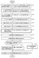
- FIG. 3 is a flowchart showing the processing contents for controlling the power supplied to the load by the power control apparatus according to Embodiment 1 of the present invention.
- FIG. 4 is an explanatory diagram showing processing timing of the power control apparatus. This indicates that the processing of the nth control cycle is executed near the boundary between the (n-1) th control cycle and the nth control cycle.
- the operation will be described in the case where the processing of the nth control cycle is performed at the beginning of the nth control cycle.
- the nth time Power is supplied to the load 1-m during the control cycle.
- the instruction of the on / off device control unit 26 for the power supply on / off device 15-m of the load 1-m is off in the process of the nth control cycle, the load 1-m is not applied during the nth control cycle. Power is not supplied.
- the output power measuring unit 16 measures the voltage V m (n ⁇ 1) applied to the load 1-m and the current I m (n ⁇ 1) flowing through the load 1-m. are composed of a current measuring means, in n-1 control cycle, a voltage V m (n-1) measured by said voltage measuring means, the current measured by the current measuring means I m (n -1) , a power measurement value q m (n-1) tilde, which is the value of the power supplied to the load 1-m, is calculated at the beginning of the nth control cycle (step ST1 in FIG. 2).
- the on-power estimation unit 17 stores the power measurement value measured by the output power measurement unit 16 when power is supplied to the loads 1-1 to 1-M (stores the power measurement value for each load).
- the power measurement value qm (n-1) tilde calculated at the beginning of the nth control cycle is not zero (the load 1-m is supplied with power).
- the stored power measurement value is updated (step ST2). If the power measurement value q m (n-1) tilde measured in the (n-1) th control cycle is zero, the stored power measurement value is not updated. Further, the on-power estimating unit 17 supplies power to the load 1-m during the unit time of the n-th control cycle based on the stored on-power measurement value in the n-th control cycle. the power value when estimated at the beginning of the n th control cycle, and outputs the power estimation value q mon tilde off device control unit 26 (step ST2).
- the power measurement value q m (n ⁇ 1) tilde calculated at the beginning of the nth control cycle is used as the load 1 Output to the on / off device control unit 26 as an estimated power value q mon tilde of ⁇ m.
- the power measurement value q m (n ⁇ 2) tilde calculated at the beginning of the (n ⁇ 1) th control cycle is output to the on / off device control unit 26 as the power estimation value q mon tilde of the load 1-m.
- the measured power adjustment unit 23 Upon receiving the power measurement value q m (n ⁇ 1) tilde calculated at the beginning of the nth control cycle, the measured power adjustment unit 23 receives the power value adjustment coefficient K 2 ( n ⁇ 1) th control cycle. n-1) (power measurement which will be described later) for the power value adjusting coefficient K n q m (n-1 ) is multiplied to the tilde, adjusts its power measurement q m (n-1) tilde, The adjusted power measurement value q m (n ⁇ 1) 'tilde is output to the intermediate integrated power value calculation unit 25 (step ST3).
- Step ST4 When the subtracter 25a-m of the intermediate integrated power value calculation unit 25 receives the adjusted power measurement value q m (n-1) 'tilde from the measurement power adjustment unit 23 in the nth control cycle,
- the value after passing through the buffer (Z ⁇ 1 ) 25c-m meaning time shift, that is, the intermediate integrated power value s m (n ⁇ 1) hat calculated in the (n ⁇ 1) th control cycle
- Power measurement value q m (n-1) 'By subtracting the tilde the power difference integrated value s m (n-1) up to the (n-1) th control cycle is calculated, and the power difference integrated value s m (n ⁇ 1) is output to the adjustment coefficient calculation integrated value calculation unit 18 and the adder 25b-m.
- the output target value input unit 12 of the target power value calculation unit 11 inputs the output target value A mn of the power supplied to the load 1-m output from the controller 2-m at the beginning of the nth control cycle.
- the output target value A mn is output to the target power value calculation processing unit 14-m.
- Target power value calculation section 14-m of the target power value calculation unit 11, in the n th control cycle receives the output target value A mn from the output target value input section 12, for the output target value A mn , by multiplying the reference power value q m stored by the reference power value storing section 13, calculates a target power value x mn of the load 1-m, the target power value x mn peak power suppressing calculator 24 And it outputs to the integrated value calculation part 18 for adjustment coefficient calculation (step ST5).
- the reference power value q m is the rated power of the load 1-m, but is not limited to the rated power of the load 1-m.
- x mn A mn ⁇ q m (4)
- the adder 25b-m of the intermediate integrated power value calculation unit 25 includes the power difference integrated value sm (n-1) until the subtracter 25a-m reaches the (n-1) -th control cycle. Is calculated by adding the power difference integrated value s m (n-1) to the target power value x mn calculated by the target power value calculation processing units 14-1 to 14-M, which will be described later.
- the intermediate integrated power value s mn hat in the control cycle is calculated, and the intermediate integrated power value s mn hat is output to the on / off device controller 26 and the buffer (Z ⁇ 1 ) 25c-m (step ST6).
- the buffer (Z -1) 25c-m of Z -1 is an operator refers to the time shift to the previous, intermediate accumulated power value s m (n whose output is calculated in n-1 control cycle -1) A hat.
- the on / off device control unit 26 of the peak power suppression calculation unit 24 determines on / off of the power supply on / off device 15-m in the n-th control cycle (step ST7). Details of processing contents of the on / off device control unit 26 will be described later.
- the adder 18a-m of the adjustment coefficient calculation integrated value calculation unit 18 uses the power from the subtracter 25a-m of the intermediate integrated power value calculation unit 25 to the (n-1) th control cycle.
- the difference integrated value s m (n-1) is received and the target power value x mn of the load 1-m is received from the target power value calculation unit 11
- the power difference integrated value s m (n-1) and the target power value By adding x mn , the adjustment coefficient calculation integrated value s mn ′ hat for the load 1-m is calculated, and the adjustment coefficient calculation integrated value s mn ′ hat is supplied to the total adjustment coefficient calculation integrated value calculation unit 19.
- Output step ST8.
- the total adjustment coefficient calculation integrated value calculation unit 19 adds the adjustment coefficient calculation integrated value s 1n 'hat to s from the adjustment coefficient calculation integrated value calculation unit 18.
- the adjustment coefficient calculation integrated value s 1n ′ hat to s Mn ′ hat is calculated as a total adjustment coefficient calculation integrated value ⁇ s n ′, and the total adjustment coefficient calculation integrated value.
- the ⁇ s n ′ hat is output to the power value adjustment coefficient calculation unit 21 (step ST9).
- the adjustment coefficient calculation integrated value s mn ′ hat is the same value as the intermediate integrated power value s mn hat.
- the adjustment coefficient calculation integrated value s mn ′ hat is not the adjustment coefficient calculation integrated value s mn ′ hat.
- the intermediate integrated power value s mn hat may be received from the value calculating unit 25 and the total adjustment coefficient calculating integrated value ⁇ s n ′ hat may be calculated.
- the power value adjustment coefficient calculation unit 21 When the power value adjustment coefficient calculation unit 21 receives the total adjustment coefficient calculation integration value ⁇ s n ′ hat from the total adjustment coefficient calculation integration value calculation unit 19 in the n-th control cycle, the total adjustment coefficient calculation integration value ⁇ s n ′ hat is compared with the power upper limit value s J stored in the power upper limit storage unit 20 (step ST10). If the total adjustment coefficient calculation integrated value ⁇ s n ′ hat is larger than the power upper limit value s J ( ⁇ s n ′ hat> s J ), the power value adjustment coefficient calculation unit 21 calculates the total adjustment coefficient calculation integrated value ⁇ s n.
- the buffer It outputs to (Z ⁇ 1 ) 22 (step ST12).
- the power value adjustment coefficient K n ⁇ 1 calculated at the beginning of the ( n ⁇ 1 ) th control cycle is used in the processing of the next control cycle as indicated by the buffer (Z ⁇ 1 ) 22.
- the power value adjustment coefficient K (n ⁇ 1) in the (n ⁇ 1) th control cycle is output to the measured power adjustment unit 23.
- Power value adjustment factor K n which is set to calculate or "1" by the power value adjusting coefficient calculation unit 21 is stored for use in the next control cycle (step ST13).
- the on / off device control unit 26 of the peak power suppression calculation unit 24 clears a later-described total power estimated value ⁇ q on as an initialization process for each control cycle (step ST21 in FIG. 3).
- the on-off device control unit 26 When the on-off device control unit 26 receives the intermediate integrated power values s 1n hat to s Mn hat at the loads 1-1 to 1-M from the intermediate integrated power value calculation unit 25 in the n-th control cycle, The integrated power values s 1n hat to s Mn hat are compared, the M intermediate integrated power values s 1n hat to s Mn hat are sorted in descending order, and the load 1 ⁇ Set to control objects in order from m. That is, among the loads 1-m that have not yet been set as control targets, the load 1-m with the largest intermediate integrated power value s mn hat is set as the control target (step ST22).
- the control target is “load 1-1” ⁇ “ Set in the order of “Load 1-2” ⁇ “Load 1-3”.
- the control target is “load 1-3” ⁇ “load 1-1” ⁇ “load Set in the order of “1-2”.
- the on / off device control unit 26 compares the intermediate integrated power value s mn hat of the load 1-m with a predetermined threshold value s th (step ST23), and the load
- a predetermined threshold value s th When the 1-m intermediate integrated power value s mn hat is larger than the predetermined threshold value s th, an on / off determination is made by adding a power estimated value q mon tilde of the load 1-m to a total power estimated value ⁇ q on described later.
- a total power estimated value ⁇ q on ′ is calculated (step ST24).
- the on / off device control unit 26 When the control target is set to the load 1-m, the on / off device control unit 26 has the intermediate integrated power value s mn hat of the load 1-m larger than the predetermined threshold s th (step ST23), and the on / off determination total It is determined whether or not the power estimation value ⁇ q on ′ satisfies a power supply condition that does not become higher than the power upper limit value s J (step ST25). That is, it is determined whether the following formulas (8) and (9) are satisfied.
- the on / off device control unit 26 When the equations (8) and (9) are satisfied, the on / off device control unit 26 satisfies the above power supply condition, so that the power supply on / off device 15-m of the load 1-m is turned on ( ON) (step ST26). As a result, power is supplied to the load 1-m.
- the on / off device control unit 26 does not satisfy the above power supply condition when at least one of the equations (8) and (9) is not satisfied, and therefore the power supply on / off device 15-m of the load 1-m Control to the cut-off state (off) (step ST27). As a result, no power is supplied to the load 1-m.
- the on / off device control unit 26 in the n-th control cycle, sums the power estimation values q mon tilde of the loads 1-1 to 1-M estimated by the on-power estimation unit 17 (hereinafter referred to as “total power estimation value ⁇ q on”). Is calculated) (step ST28).
- the on / off device control unit 26 sets the control target in order starting from the load 1-m related to the intermediate integrated power value having a large value, and performs the above-described control processing (steps ST22 to ST22) until the control for all the loads 1-m is completed.
- the process of ST28 is repeated (step ST29).
- FIG. 5 is an explanatory diagram showing an example of control in each control cycle by the power control apparatus.
- the target power value the intermediate integrated power value, the actual power value (power measurement value), and the power difference integrated value are expressed in%.
- the target power value is set to 30% of the rated power of the load
- the average value of the actual power value is controlled to 30% as shown in FIG. I understand.
- the target power value is set to 55% of the rated power of the load
- the average value of the actual power value (power measurement value) is controlled to 55% as shown in FIG. 5B. I understand.
- FIG. 6 is an explanatory diagram showing the target power value (target output power), the measured power value (average output power), and the achievement rate of the average output power with respect to the target output power for each of the control loads 1-1 to 1-M. .
- (a) is related to the power control apparatus of the first embodiment
- (b) is related to the conventional power control apparatus.
- each load (control channel) Although the achievement rate of the average output power with respect to the target output power of ch) is not uniform, in the power control apparatus of the first embodiment, the achievement of the average output power with respect to the target output power of each load (control channel ch) is achieved. The rate is uniform.
- the power difference integrated value s mn of the load 1-m is calculated from the threshold s th to the power measurement value q mn tilde. Becomes a finite value between the subtracted value and the threshold value s th .
- the power difference integrated value s mn of the load 1-m can be divided into an integrated value of the target power value x mn and an integrated value of the power measurement value q mn tilde.
- the integrated value of the target power value x mn and the integrated value of the power measurement value q mn tilde become very large values.
- the power difference integrated value s mn is sufficiently small compared to the integrated value of the target power value x mn and the integrated value of the power measurement value q mn tilde, so the integrated value and power of the target power value x mn
- the measured value q mn tilde is almost equal to the integrated value.
- the mathematical expression indicates that the target power value x mn matches the power measurement value q mn tilde.
- the power supply on / off device 15-m of the load 1-m is turned on (ON).
- the total of the power measurement value q mn tilde is suppressed to be equal to or less than the power upper limit value s J in the unit time of each control cycle.
- total target power value when the total value of target power values x mn of all loads (hereinafter referred to as “total target power value”) exceeds the power upper limit value s J , the sum of the power measurement values q mn tilde is equal to or less than the power upper limit value s J. to be suppressed, the power difference integration value s mn of each load gradually increases, so that the saturation calculation on the upper limit of the power difference integration value s mn. In such a state, the power difference integrated value s mn of each load sequentially becomes a saturation value in calculation, and the intermediate integrated power value s mn hat is the power difference integrated value s m (n for the previous unit time.
- the target power value x mn of the current unit time is added to the saturation value of -1) , and the intermediate integrated power value s mn hat becomes larger as the target power value x mn becomes larger.
- the intermediate integrated power value s mn hat becomes larger as the target power value x mn becomes larger.
- the processing order cannot be appropriately determined, and the ratio of the power measurement value q mn tilde to the target power value x mn of each load (hereinafter referred to as “output achievement rate”) becomes a non-uniform value for each load. is there.
- the first embodiment by multiplying the power value adjustment factor K n with respect to a measured value of power supplied to a control target load power measurements q mn tilde
- the power measurement value q mn tilde which is a reduction factor of the power difference integrated value s mn , is set to an apparently large value.
- the phenomenon that the power difference integrated value s mn and the intermediate integrated power value s mn hat become a saturation value in calculation is prevented, so that even when the total target power value exceeds the power upper limit value s J , time division is performed.
- the control processing order is appropriately determined, and the phenomenon that the output achievement rate becomes uneven for each load is prevented.
- the power value adjustment factor K n Since peak power suppression control is performed so that the number of channels to be turned on is limited so that the total output power measurement value multiplied by is always smaller than the power upper limit value s J , it is simultaneously supplied to the load to be controlled. The total value of power becomes a discrete value.
- the value increases by multiplying the power value adjustment factor K n to the power measurements q mn tilde, an intermediate integral power value s mn hat each load tends to reduce the amount, the smaller the power value adjustment factor K n The saturation of the intermediate integrated power value s mn hat can be prevented.
- the power value adjustment coefficient is too small and over-adjusted, the adjustment value of the output power measurement value is small, so the total intermediate integrated value is small and the power value adjustment coefficient Kn is small.
- the power value adjustment factor L value decreases multiplied in power measurements q mn tilde, intermediate accumulated power value s mn hat becomes increasing, it no power value adjustment factor K n is unilaterally reduced Is maintained at an appropriate value (in other words, it is in an equilibrium state).
- the power upper limit value s J a power value divided by the total intermediate power integration value value adjustment factor K n, by the small value of the target power value is adjusted by the power value adjusting coefficient K n, the total target power Even when the value exceeds the power upper limit value s J , saturation of the intermediate integrated power value s mn hat can be prevented, so that a phenomenon in which the output achievement rate becomes uneven for each load can be prevented.
- the output power measuring unit 16 that measures the power measurement value that is the value of the power supplied to the load 1-m, and each load 1-m.
- An on-power estimation unit 17 that estimates a power value when power is supplied during a unit time of the next control cycle from a power measurement value measured by the output power measurement unit 16 when power is supplied;
- the power measurement value q m (n-1) 'tilde adjusted by the measured power adjustment unit 23 from the intermediate integrated power value S m (n-1) hat calculated in the previous control cycle (n-1) By subtracting, the power difference integrated value sm (n-1) in the previous control cycle (n-1 ) is calculated, and the power difference integrated value Sm (n-1) and the target power value calculating process
- an intermediate integrated power value calculation unit 25 for calculating the latest intermediate integrated power value s mn hat, and the on / off device control unit 26 is calculated by the intermediate integrated power value calculation unit 25 for
- the intermediate integrated power value of the load 1-m is greater than a predetermined threshold, and the estimated power q mon tilde of the load 1-m estimated by the on-power estimation unit 17 and the on-power estimation unit 17 are estimated.
- the sum of the estimated power values q 1 on tilde to q Mon tilde of the loads 1-1 to 1-M, which has already been determined to be turned on in the next control cycle, is higher than the power upper limit value s J If the power supply condition that is not satisfied is satisfied, the power supply ON / OFF device 15-m of the load 1-m is controlled to be in the on state (ON). If the power supply condition is not satisfied, the power supply of the load 1-m is supplied.
- the device 15-m is configured to be controlled to be turned off (off), it is possible to suppress fluctuations in the power supplied to the load 1-m even if fluctuations in power supply voltage or load fluctuations occur. There is an effect that the total amount of power supplied to all loads can be suppressed within the power upper limit value.
- the difference between the intermediate integrated power value calculated by the intermediate integrated power value calculator 25 and the measured power value is calculated by the target power value calculator 11.
- An adjustment coefficient calculation integrated value is calculated by adding to the calculated target power value, and if the sum of the adjustment coefficient calculation integrated values for each load 1-m is larger than the power upper limit value, the adjustment coefficient calculating integrated value Is calculated as a power value adjustment coefficient, and if the sum of the adjustment coefficient calculation integrated values is smaller than the power upper limit value, the power value adjustment coefficient is set to 1 and each load 1 Since the power measurement value is adjusted for each -m using the power value adjustment coefficient, it is possible to prevent a situation where the ratio between the target value of power and the amount of supplied power differs depending on the load. Play.
- FIG. 7 is a block diagram showing a power control apparatus according to Embodiment 2 of the present invention.
- the power value adjustment coefficient calculation unit 31 is composed of, for example, a semiconductor integrated circuit mounted with a CPU or a one-chip microcomputer, and is used for calculating the total adjustment coefficient calculated by the total adjustment coefficient calculation integrated value calculation unit 19.
- the integrated value ⁇ s n ′ hat is compared with the power upper limit value s J stored in the power upper limit storage unit 20, and if the total adjustment coefficient calculation integrated value ⁇ s n ′ hat is larger than the power upper limit value s J ( ⁇ s n 'hat> s J), the total adjustment coefficient calculating integrated value?
- the target power adjustment unit 32 includes, for example, a multiplier, and a power value adjustment coefficient calculation unit for the target power value x mn calculated by the target power value calculation processing unit 14-m of the target power value calculation unit 11 by multiplying the power value adjustment factor K n which is calculated by 31, it carries out a process of adjusting the target power value x mn.
- the adjustment coefficient calculation integrated value calculation unit 18, the total adjustment coefficient calculation integrated value calculation unit 19, the power upper limit value storage unit 20, the power value adjustment coefficient calculation unit 31, and the target power adjustment unit 32 constitute an adjustment unit. Yes.
- a target power value calculation unit 11 power supply on / off devices 15-1 to 15 -M, output power measurement unit 16, on-power estimation unit 17, adjustment coefficient calculation integration, which are components of the power control device.
- Value calculation unit 18, total adjustment coefficient calculation integrated value calculation unit 19, power upper limit value storage unit 20, power value adjustment coefficient calculation unit 31, target power adjustment unit 32, intermediate integrated power value calculation unit 25, and on / off device control unit 26 are assumed to be configured by dedicated hardware, but all or part of the power control apparatus may be configured by a computer.
- the power upper limit storage unit 20 is configured on the memory of the computer, the target power value calculation unit 11, the power supply on / off devices 15-1 to 15-M, the output Power measurement unit 16, on-power estimation unit 17, adjustment coefficient calculation integrated value calculation unit 18, total adjustment coefficient calculation integrated value calculation unit 19, power value adjustment coefficient calculation unit 31, target power adjustment unit 32, intermediate integrated power value
- a program describing the processing contents of the calculation unit 25 and the on / off device control unit 26 may be stored in the memory of a computer, and the CPU of the computer may execute the program stored in the memory.
- FIG. 8 is a flowchart showing the processing contents until the power control apparatus according to the second embodiment of the present invention calculates the power value adjustment coefficient.
- the processing contents for controlling the power supplied to the load by the power control apparatus are the same as those in FIG. 2 in the first embodiment.
- the measured power adjustment unit 23 measures the power measurement value q m (n ⁇ 1) measured in the (n ⁇ 1) th control cycle from the output voltage measurement unit 16 in the nth control cycle.
- the power value adjustment coefficient K (n ⁇ 1) calculated in the (n ⁇ 1) th control cycle as shown by the buffer (Z ⁇ 1 ) 22 is used as the power measurement value q m (n ⁇ 1) tilde.
- a target power adjustment unit 32 is mounted in place of the measurement power adjustment unit 23 as shown in FIG. 7 to adjust the power measurement value q m (n ⁇ 1) tilde by multiplying by.
- the target power adjustment unit 32 performs the power value adjustment coefficient in the (n ⁇ 1) th control cycle with respect to the target power value x mn calculated by the target power value calculation processing unit 14-m of the target power value calculation unit 11. calculated by the calculation unit 31 power value adjustment factor K n-1) by multiplying the may be adjusted the target power value x mn, it is possible to obtain the same advantages as the first embodiment.
- the power value adjustment coefficient calculation unit 31 receives the total adjustment coefficient calculation integrated value ⁇ s n ′ hat from the total adjustment coefficient calculation integrated value calculation unit 19 in the n-th control cycle, the power value adjustment coefficient calculation unit 31 calculates the power value adjustment coefficient of FIG. Similarly to the unit 21, the total adjustment coefficient calculation integrated value ⁇ s n ′ hat is compared with the power upper limit value s J stored in the power upper limit storage unit 20 (step ST32 in FIG. 8).
- the target power adjustment unit 32 adjusts the target power value x mn , as in the first embodiment, even if a power supply voltage fluctuation or a load fluctuation occurs, the load The fluctuation of the power supplied to 1-m can be suppressed, and the total amount of power supplied to all loads can be suppressed within the power upper limit value.
- the second embodiment for each respective load 1-m, by using the power value adjustment factor K n, and then, is adjusted target power value x mn, power ratio of the target value and the amount of power supplied However, the effect which can prevent the situation which changes for every load is produced.
- Embodiment 3 the target power value x mn of the load 1-m calculated by the target power value calculation unit 11 and the power measurement value q mn tilde measured by the output power measurement unit 16 are normalized values. Instead, actual power is shown in which various calculations are performed. However, the target power value x mn and the power measurement value q mn tilde are converted into normalized values, and various calculations are performed as normalized values. It may be.
- the target power value calculation unit 41 inputs the normalized target power value (normalized target power value) of the load 1-m from the controller 2-m for each control cycle n, and loads the normalized target power value as a load. A process of outputting as a target power value x mn of 1-m is performed.
- the target power value calculation unit 41 constitutes a target power value calculation unit. Normalized target power value input units 41a-1 to 41a-M are interface devices for the controllers 2-1 to 2-M, and the normalized target power values output from the controller 2-m are supplied to the load 1-m. Processing to output as the target power value x mn is performed.
- the reference power value storage unit 42 is composed of a memory such as a RAM, for example, and stores a reference power value q m (for example, rated power) of the load 1-m.
- the power normalization unit 43 is composed of, for example, a divider and uses the power measurement value q m (n ⁇ 1) tilde measured in the previous control cycle (n ⁇ 1) output from the output voltage measurement unit 16 as a reference. By dividing by the reference power value q m stored in the power value storage unit 42, the power measurement value q m (n ⁇ 1) tilde is converted into a normalized value, and the normalized power measurement value q m (N-1) A process of outputting the tilde to the measured power adjustment unit 23 is performed.
- the power normalization unit 43 constitutes a power measurement unit.
- the power value conversion unit 44 includes, for example, a multiplier. For the normalized value calculated by the adjustment coefficient calculation integrated value calculation unit 18, the adjustment value calculation integrated value s mn ′ hat for the load 1-m is used. Then, by multiplying the reference power value q m stored in the reference power value storage unit 42, the normalized value adjustment coefficient calculation integrated value s mn ′ is converted into actual power, and after the actual power conversion The adjustment coefficient calculation integrated value s mn ′ is output to the total adjustment coefficient calculation integrated value calculation unit 19.
- the power value conversion unit 44 constitutes an adjustment unit.
- the calculation by the adjustment coefficient calculation integrated value calculation unit 18, the measured power adjustment unit 23, and the peak power suppression calculation unit 24 is performed with the normalized values. In this case, the same effect as in the first embodiment can be obtained.
- FIG. 10 is a block diagram showing a power control apparatus according to Embodiment 3 of the present invention.
- the same reference numerals as those in FIGS. 7 and 9 denote the same or corresponding parts.
- the power control device in FIG. 10 is one in which the power control device in FIG. 7 handles the normalized value, but in this case as well, the same effect as in the second embodiment can be obtained.
Landscapes
- Physics & Mathematics (AREA)
- General Physics & Mathematics (AREA)
- Engineering & Computer Science (AREA)
- Automation & Control Theory (AREA)
- Control Of Electrical Variables (AREA)
- Supply And Distribution Of Alternating Current (AREA)
Priority Applications (2)
| Application Number | Priority Date | Filing Date | Title |
|---|---|---|---|
| PCT/JP2012/068675 WO2014016899A1 (fr) | 2012-07-24 | 2012-07-24 | Dispositif de commande de puissance et procédé de commande de puissance |
| JP2014526636A JP5930039B2 (ja) | 2012-07-24 | 2012-07-24 | 電力制御装置及び電力制御方法 |
Applications Claiming Priority (1)
| Application Number | Priority Date | Filing Date | Title |
|---|---|---|---|
| PCT/JP2012/068675 WO2014016899A1 (fr) | 2012-07-24 | 2012-07-24 | Dispositif de commande de puissance et procédé de commande de puissance |
Publications (1)
| Publication Number | Publication Date |
|---|---|
| WO2014016899A1 true WO2014016899A1 (fr) | 2014-01-30 |
Family
ID=49996736
Family Applications (1)
| Application Number | Title | Priority Date | Filing Date |
|---|---|---|---|
| PCT/JP2012/068675 Ceased WO2014016899A1 (fr) | 2012-07-24 | 2012-07-24 | Dispositif de commande de puissance et procédé de commande de puissance |
Country Status (2)
| Country | Link |
|---|---|
| JP (1) | JP5930039B2 (fr) |
| WO (1) | WO2014016899A1 (fr) |
Citations (6)
| Publication number | Priority date | Publication date | Assignee | Title |
|---|---|---|---|---|
| JPH06309043A (ja) * | 1993-04-27 | 1994-11-04 | Rika Kogyo Kk | Ac電力制御装置 |
| JPH11262174A (ja) * | 1998-03-10 | 1999-09-24 | Tokyo Electron Ltd | 電力制御方法及びその装置 |
| JP2004164431A (ja) * | 2002-11-14 | 2004-06-10 | Rkc Instrument Inc | 調節計 |
| JP2004164432A (ja) * | 2002-11-14 | 2004-06-10 | Rkc Instrument Inc | Ac電力制御装置 |
| JP4529153B1 (ja) * | 2009-11-27 | 2010-08-25 | 理化工業株式会社 | マルチチャンネル電力制御器 |
| WO2011118103A1 (fr) * | 2010-03-24 | 2011-09-29 | 理化工業株式会社 | Régulateur de puissance multicanal |
-
2012
- 2012-07-24 WO PCT/JP2012/068675 patent/WO2014016899A1/fr not_active Ceased
- 2012-07-24 JP JP2014526636A patent/JP5930039B2/ja active Active
Patent Citations (6)
| Publication number | Priority date | Publication date | Assignee | Title |
|---|---|---|---|---|
| JPH06309043A (ja) * | 1993-04-27 | 1994-11-04 | Rika Kogyo Kk | Ac電力制御装置 |
| JPH11262174A (ja) * | 1998-03-10 | 1999-09-24 | Tokyo Electron Ltd | 電力制御方法及びその装置 |
| JP2004164431A (ja) * | 2002-11-14 | 2004-06-10 | Rkc Instrument Inc | 調節計 |
| JP2004164432A (ja) * | 2002-11-14 | 2004-06-10 | Rkc Instrument Inc | Ac電力制御装置 |
| JP4529153B1 (ja) * | 2009-11-27 | 2010-08-25 | 理化工業株式会社 | マルチチャンネル電力制御器 |
| WO2011118103A1 (fr) * | 2010-03-24 | 2011-09-29 | 理化工業株式会社 | Régulateur de puissance multicanal |
Also Published As
| Publication number | Publication date |
|---|---|
| JPWO2014016899A1 (ja) | 2016-07-07 |
| JP5930039B2 (ja) | 2016-06-08 |
Similar Documents
| Publication | Publication Date | Title |
|---|---|---|
| JP5975107B2 (ja) | 電力制御装置及び電力制御方法 | |
| CN104106203B (zh) | 开关模式电源的电压前馈补偿和电压反馈补偿 | |
| JP2015138864A (ja) | 太陽光発電装置の出力推定方法および装置並びにこれを用いた電力系統監視装置 | |
| JP5930039B2 (ja) | 電力制御装置及び電力制御方法 | |
| JP5581528B1 (ja) | 制御パラメータ決定装置、方法、及びプログラム、並びに、制御器及び最適化制御システム | |
| CN104937833A (zh) | 控制电转换器 | |
| JP5716961B2 (ja) | 無効電力補償装置の制御装置 | |
| JP4407616B2 (ja) | 電力制御方法、電力制御装置および温度調節器 | |
| KR20020036606A (ko) | 오에프디엠 출력 비트 신호 보상을 위한 고속 퓨리에 변환장치 및 방법 | |
| JP5242084B2 (ja) | 受水流量算出方法および装置 | |
| WO2015056293A1 (fr) | Dispositif de commande de puissance et procédé de commande de puissance | |
| JP6727449B2 (ja) | 系統制御装置および方法 | |
| KR101050197B1 (ko) | 선형 시스템 제어장치 및 방법 | |
| JP6140427B2 (ja) | モデル予測制御装置および方法 | |
| CN114362123B (zh) | 直流集中供电-分散耗电系统的下垂控制方法和系统 | |
| JP2013027196A (ja) | 受電デマンド監視制御方法および自家用発電プラント | |
| CN115769172B (zh) | 处理器和变量的预测方法 | |
| JP2019129644A (ja) | 電力潮流計算装置 | |
| JP2020021298A (ja) | 制御装置および制御方法 | |
| JP2022171080A (ja) | 電力制御装置 | |
| JP6504268B2 (ja) | 交流電力調整器及び交流電力制御方法 | |
| KR20180047266A (ko) | 시간지연 및 입력 외란이 있는 제어 대상 시스템의 제어 시스템 및 방법 | |
| JP2025131109A (ja) | 最適値探索制御装置、最適値探索制御方法およびコンピュータプログラム | |
| KR101363318B1 (ko) | 터치패드 포인팅 제어방법 및 제어장치 | |
| JP2020175442A (ja) | 被矯正材の変形状態の推定方法及びローラレベラのロール押込量制御方法 |
Legal Events
| Date | Code | Title | Description |
|---|---|---|---|
| ENP | Entry into the national phase |
Ref document number: 2014526636 Country of ref document: JP Kind code of ref document: A |
|
| 121 | Ep: the epo has been informed by wipo that ep was designated in this application |
Ref document number: 12881705 Country of ref document: EP Kind code of ref document: A1 |
|
| NENP | Non-entry into the national phase |
Ref country code: DE |
|
| 122 | Ep: pct application non-entry in european phase |
Ref document number: 12881705 Country of ref document: EP Kind code of ref document: A1 |