WO2014016908A1 - Élément de fermeture pour fermeture à glissière - Google Patents
Élément de fermeture pour fermeture à glissière Download PDFInfo
- Publication number
- WO2014016908A1 WO2014016908A1 PCT/JP2012/068712 JP2012068712W WO2014016908A1 WO 2014016908 A1 WO2014016908 A1 WO 2014016908A1 JP 2012068712 W JP2012068712 W JP 2012068712W WO 2014016908 A1 WO2014016908 A1 WO 2014016908A1
- Authority
- WO
- WIPO (PCT)
- Prior art keywords
- fastener
- layer
- fastener element
- light
- light transmissive
- Prior art date
- Legal status (The legal status is an assumption and is not a legal conclusion. Google has not performed a legal analysis and makes no representation as to the accuracy of the status listed.)
- Ceased
Links
Images




Classifications
-
- C—CHEMISTRY; METALLURGY
- C23—COATING METALLIC MATERIAL; COATING MATERIAL WITH METALLIC MATERIAL; CHEMICAL SURFACE TREATMENT; DIFFUSION TREATMENT OF METALLIC MATERIAL; COATING BY VACUUM EVAPORATION, BY SPUTTERING, BY ION IMPLANTATION OR BY CHEMICAL VAPOUR DEPOSITION, IN GENERAL; INHIBITING CORROSION OF METALLIC MATERIAL OR INCRUSTATION IN GENERAL
- C23C—COATING METALLIC MATERIAL; COATING MATERIAL WITH METALLIC MATERIAL; SURFACE TREATMENT OF METALLIC MATERIAL BY DIFFUSION INTO THE SURFACE, BY CHEMICAL CONVERSION OR SUBSTITUTION; COATING BY VACUUM EVAPORATION, BY SPUTTERING, BY ION IMPLANTATION OR BY CHEMICAL VAPOUR DEPOSITION, IN GENERAL
- C23C14/00—Coating by vacuum evaporation, by sputtering or by ion implantation of the coating forming material
- C23C14/0015—Coating by vacuum evaporation, by sputtering or by ion implantation of the coating forming material characterized by the colour of the layer
-
- A—HUMAN NECESSITIES
- A44—HABERDASHERY; JEWELLERY
- A44B—BUTTONS, PINS, BUCKLES, SLIDE FASTENERS, OR THE LIKE
- A44B19/00—Slide fasteners
- A44B19/10—Slide fasteners with a one-piece interlocking member on each stringer tape
- A44B19/12—Interlocking member in the shape of a continuous helix
-
- A—HUMAN NECESSITIES
- A44—HABERDASHERY; JEWELLERY
- A44B—BUTTONS, PINS, BUCKLES, SLIDE FASTENERS, OR THE LIKE
- A44B19/00—Slide fasteners
- A44B19/24—Details
-
- C—CHEMISTRY; METALLURGY
- C23—COATING METALLIC MATERIAL; COATING MATERIAL WITH METALLIC MATERIAL; CHEMICAL SURFACE TREATMENT; DIFFUSION TREATMENT OF METALLIC MATERIAL; COATING BY VACUUM EVAPORATION, BY SPUTTERING, BY ION IMPLANTATION OR BY CHEMICAL VAPOUR DEPOSITION, IN GENERAL; INHIBITING CORROSION OF METALLIC MATERIAL OR INCRUSTATION IN GENERAL
- C23C—COATING METALLIC MATERIAL; COATING MATERIAL WITH METALLIC MATERIAL; SURFACE TREATMENT OF METALLIC MATERIAL BY DIFFUSION INTO THE SURFACE, BY CHEMICAL CONVERSION OR SUBSTITUTION; COATING BY VACUUM EVAPORATION, BY SPUTTERING, BY ION IMPLANTATION OR BY CHEMICAL VAPOUR DEPOSITION, IN GENERAL
- C23C14/00—Coating by vacuum evaporation, by sputtering or by ion implantation of the coating forming material
- C23C14/06—Coating by vacuum evaporation, by sputtering or by ion implantation of the coating forming material characterised by the coating material
- C23C14/08—Oxides
- C23C14/083—Oxides of refractory metals or yttrium
-
- Y—GENERAL TAGGING OF NEW TECHNOLOGICAL DEVELOPMENTS; GENERAL TAGGING OF CROSS-SECTIONAL TECHNOLOGIES SPANNING OVER SEVERAL SECTIONS OF THE IPC; TECHNICAL SUBJECTS COVERED BY FORMER USPC CROSS-REFERENCE ART COLLECTIONS [XRACs] AND DIGESTS
- Y10—TECHNICAL SUBJECTS COVERED BY FORMER USPC
- Y10T—TECHNICAL SUBJECTS COVERED BY FORMER US CLASSIFICATION
- Y10T24/00—Buckles, buttons, clasps, etc.
- Y10T24/25—Zipper or required component thereof
- Y10T24/2518—Zipper or required component thereof having coiled or bent continuous wire interlocking surface
Definitions
- the present invention relates to a slide fastener. More specifically, the present invention relates to a fastener element for a slide fastener (hereinafter referred to as a fastener element) to which a decoration is added, and a slide fastener including the element.
- a fastener element for a slide fastener (hereinafter referred to as a fastener element) to which a decoration is added, and a slide fastener including the element.
- JP 2001-178508 A discloses a fastener element in which a metal coating layer is formed, and the upper surface excluding the outer surface of the fastener element that is in sliding contact with the guide flange. By forming the coating on the metal coating layer, the phenomenon that the metal coating layer is scraped off and the metal powder is scattered is prevented.
- the fastener elements obtained by the prior art have a very simple appearance from the viewpoint of decorativeness, and it was impossible to express various colors and patterns by the coating. Further, when a coating is formed to improve the decorativeness as in the prior art, problems such as peeling or cracking of the coating have occurred if it is continuously used.
- An object of the present invention is to provide a fastener element whose color and pattern are variously changed depending on an observation angle. Another object of the present invention is to provide a fastener element that is less likely to cause peeling and cracking of a decorative coating.
- the present invention provides a fastener element having the following characteristics: (1) A coil-shaped fastener element for a slide fastener to be attached to a fastener tape,
- the fastener element includes a meshing head, an upper leg, a lower leg, and an inversion part that connects the upper leg and the lower leg.
- a coating including at least one light transmissive layer is formed on at least the upper leg;
- the layer thickness of the light-transmitting layer is formed so as to gradually decrease from a substantially top portion of the upper leg portion toward the fastener tape side,
- the thickness of the substantially top portion is about 50 to about 1500 nm at the maximum (in some cases, excluding the resin film thickness (not including the resin top coat), the maximum is about 50 to about 1500 nm), Fastener element for slide fastener.
- the light transmissive layer includes at least two light transmissive layers stacked, and light is reflected at at least one interface formed by the at least two light transmissive layers.
- the fastener element for slide fasteners as described in (1) or (2).
- the light transmissive layer is formed by laminating three or more light transmissive layers, and laminated so that the relative refractive index of two adjacent layers alternately becomes high / low.
- the fastener element for a slide fastener according to any one of (1) to (3), which is formed.
- the light-transmitting layer is a dielectric (e.g., TiO 2, Ta 2 O 5 , Nb 2 O 5, ZrO 2, HfO 2, Sb 2 O 3, CeO 2, ZnO, AlN, La 2 O 3 , Gd 2 O 3 , Al 2 O 3 , SiO 2 , MgF 2 , MgO, Si 3 N 4, etc., and the material may not be a stoichiometric ratio).
- Conductive compounds, colored compounds ITO (In 2 O 3 : SnO 2 (5-10%)), SnO 2 , In 2 O 3 , TiN, Cr 2 O 3 , TiC, ZrC, NbC, TaC
- the material may not have a stoichiometric ratio) or the fastener element for a slide fastener according to the above (6), wherein the layer thickness of the layer containing metal / semiconductor is 100 nm or less.
- a layer containing metal (including a semiconductor) as a material is between the coating and the upper leg.
- a slide fastener comprising the fastener element according to any one of (1) to (11) above.
- the fastener element of the present invention since the fastener element of the present invention has a light-transmitting thin film (layer) at the outer peripheral portion of the upper leg portion to be visually recognized, an interference pattern can be formed.
- the film thickness layer thickness
- the film thickness is formed so as to gradually decrease, different interference patterns formed with different film thicknesses can be obtained depending on the observation angle. it can.
- the film thickness is in an appropriate range, cracks and the like are hardly generated.
- the fastener element of the present invention has a structure in which the edge of the outer peripheral direction of the film is formed to extend beyond the center line in the horizontal direction of the cross section toward the fastener tape, and therefore the film is less likely to peel. .
- the fastener element of the present invention forms an interface when the coating includes at least two light transmissive layers as a laminate.
- Various colors and complex interference patterns can be formed by the reflected light from the interface.
- a high refractive index layer and a low refractive index layer are alternately laminated, so that reflected light from a plurality of interfaces can be obtained, thereby forming a more complicated interference pattern. Can do.
- the fastener element of the present invention can enhance a specific color tone by making at least one of the light transmissive layers a colored layer.
- the fastener element of the present invention can improve the surface durability by having a layer containing a resin as a material as the outermost layer.
- the fastener element of the present invention can enhance the color tone due to interference of reflected light by forming a metal layer as a base layer formed under the coating.
- the slide fastener of the present invention is provided with the above-described fastener element, so that it is possible to obtain a hue (color tone varies depending on the observation angle) that could not be obtained by the prior art. Furthermore, since it can be semi-reflected while showing the color of the background, a complicated color tone can be given. It can be used for high-grade clothing such as silk, and can be used for various coloring and pale fabrics.
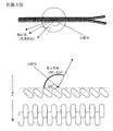
- the whole figure of a slide fastener provided with the fastener element which concerns on one Embodiment of this invention is represented.
- the enlarged view of the fastener element which concerns on one Embodiment of this invention is represented.
- Sectional drawing of the upper leg part of the fastener element which concerns on one Embodiment of this invention is represented.
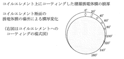
- the film thickness change of the film formed on the monofilament of the fastener element which concerns on one Embodiment of this invention, and the measuring method are represented.
- 3 represents a method for observing a change in color tone of a fastener element according to an embodiment of the present invention.
- the color tone change of the fastener element which concerns on one Embodiment of this invention is represented.
- the color tone change of the fastener element which concerns on one Embodiment of this invention is represented.
- the color tone change by the number of layers and film thickness of the fastener element which concerns on one Embodiment of this invention is represented.
- the crack generation by the film thickness of the fastener element which concerns on one Embodiment of this invention is represented.
- FIG. 1 shows a configuration of an entire slide fastener 1 including a fastener element of the present invention according to an embodiment.
- a coil-shaped fastener element 2 according to an embodiment of the present invention is sewn to a fastener tape 10 with a sewing thread 12.
- the fastener element 2 includes a meshing head 6, and a pair of opposing meshing heads mesh with each other when the slider 17 slides.
- FIG. 2 shows the configuration of the fastener element of the present invention according to one embodiment.
- the fastener element 2 forms the coiled fastener element 2 by winding the monofilament 22 into a coil shape.
- the coiled fastener element 2 includes a meshing head 6, an upper leg portion 7, a lower leg portion 8, and an inversion portion 9 that connects the upper leg portion 7 and the lower leg portion 8.
- the material of a fastener element is not specifically limited, For example, resin (PET etc.) can be used. Further, the material of the fastener element may be colorless and transparent, or may be colored. Further, as described later, a metal layer may be coated as a base.
- the cross-sectional view of the upper leg portion is substantially circular.
- the shape of the cross section is not necessarily circular or substantially circular, and may be an ellipse, a polygon (for example, a hexagon, an octagon, a dodecagon, or the like).
- the coating 20 can be formed on the portion of the coiled fastener element 2 that is in contact with the user's eyes, that is, on the front side of the upper leg portion. More specifically, the coating film 20 is formed along the outer periphery of the cross section from the outer periphery of the cross section of the upper leg portion which is substantially the top with respect to the surface of the fastener tape 10.
- substantially the top means a portion that is the highest position with respect to the surface of the fastener tape.
- the “outer peripheral portion of the cross section” means an outer portion of the cross sectional shape when cut so as to cross the monofilament 22.
- the coating film 20 is formed so that the film thickness of the coating film gradually decreases when extending to the fastener tape 10 side (or the lower leg portion 8 side) along the outer periphery.
- the portion where the film thickness is maximum is typically a portion where the center line in the cross-sectional front / back direction in the monofilament radial direction and the outer periphery of the cross-section intersect.
- the “center line in the cross-sectional front / back direction” is a line passing through the geometric center of the cross-sectional view (for example, the intersection of the diagonal lines, the center of gravity, etc.), and the line extending perpendicularly to the fastener tape surface. means.
- the position of the maximum film thickness does not necessarily exist at the intersection, and a film thickness peak exists at a portion slightly deviated from the intersection, and the film thickness gradually decreases starting from the peak. Also good.
- a line shifted from ⁇ 45 ° to 45 °, or from ⁇ 30 ° to 30 °, or from ⁇ 15 ° to 15 ° intersects the outer periphery of the cross section.
- the coating includes at least one light transmissive layer (typically including at least one light transmissive layer on the outermost side of the coating).
- the thickness of the light-transmitting layer is about 50 to about 1500 nm, preferably about 200 to about 1500 nm, more preferably at a portion where the maximum thickness is obtained (for example, a portion where the maximum thickness is substantially at the top). , About 200 to about 800 nm, most preferably about 300 to about 500 nm.
- the thickness at the edge in the outer peripheral direction of the light-transmitting layer that is, the portion where the film thickness is the thinnest
- 100% is typically about 0 to about 80%.
- An interference pattern is formed by using a light-transmitting layer having the above thickness.
- the layer thickness gradually decreases, it is possible to obtain an interference pattern that varies depending on the observation angle.
- the maximum layer thickness is less than about 50 nm, light interference hardly occurs.
- the maximum layer thickness is more than about 1500 nm, the light-transmitting layer and the coating are liable to crack.
- the edge serving as the end point is formed so as to extend beyond the center line in the horizontal direction of the cross section of the upper leg portion toward the fastener tape 10 side.
- the “center line in the horizontal direction of the cross section” refers to the geometric center of the cross section in the monofilament radial direction (for example, the intersection of diagonal lines, the center of gravity, etc.), and is substantially parallel to both the surface of the fastener tape and the cross section. It means a line that stretches out.
- the edge of the coating extends beyond the center line in the horizontal section of the upper leg portion, the coating is structurally difficult to peel.
- any light transmissive material can be used as a material used as a layer for forming a film (light transmissive layer).
- any light transmissive material can be used.
- dielectrics, conductive compounds, colored compounds, ultrathin (several nm to several tens of nm) metals, semiconductors, and the like can be used.
- it is a dielectric, but since the dielectric behaves as an insulator that does not conduct electricity, many things exhibit light transmittance.
- Plastic, ceramic, mica, and the like oil is equivalent to the dielectric, as the ceramic dielectric are those illustrated below: For example, TiO 2, Ta 2 O 5 , Nb 2 O 5, ZrO 2, HfO 2 , Sb 2 O 3 , CeO 2 , ZnO, AlN, La 2 O 3 , Gd 2 O 3 , Al 2 O 3 , SiO 2 , MgF 2 , MgO, Si 3 N 4, etc. It doesn't have to be an argument).
- Examples of the conductive compound and the colored compound are as follows: ITO (In 2 O 3 : SnO 2 (5-10%)), SnO 2 , In 2 O 3 , TiN, Cr 2 O 3 , TiC, ZrC, NbC, TaC, etc.
- the material may not have a stoichiometric ratio.
- metals, semiconductors and the like are as follows: Ag, Al, Au, Cr, Cu, Fe, Ni, Ni—Cr, Ti, Zr, Mo, Pt, Pd, Si, and the like.
- the ratio may not be an integer ratio, and may be an arbitrary ratio.
- the interference pattern can be further diversified by appropriately using a high refractive material and a low refractive material as the light transmission layer. For example, when emphasizing surface gloss, a layer using a high refractive material is formed on the surface. On the other hand, when emphasizing the color or interference color of the substrate, a layer using a low refractive material is formed on the surface.
- Examples of the highly refractive material include TiO 2 [refractive index: 2.2-2.5 (measurement wavelength: 0.55 ⁇ m)] (hereinafter the same), Ta 2 O 5 [2-2.3 (0 0.5 ⁇ m)], Nb 2 O 5 [2.1-2.3 (0.5 ⁇ m)], ZrO 2 [2.05 (0.5 ⁇ m)], HfO 2 [1.93 (0.55 ⁇ m)], Sb 2 O 3 [2.04 (0.55 ⁇ m)], CeO 2 [2.0-2.4 (0.55 ⁇ m), ZnO [2 (0.55 ⁇ m)], AlN [1.9-2.2 (0.63 ⁇ m)], La 2 O 3 [1.95 (0.55 ⁇ m)], Gd 2 O 3 [1.92 (0.55 ⁇ m)], Si 3 N 4 [2.05 (0.55 ⁇ m)] ]
- various mixed materials including the above-mentioned materials, but are not limited thereto.
- the low refractive material examples include Al 2 O 3 [1.63 (0.55 ⁇ m)], SiO 2 [1.45-1.47 (0.55 ⁇ m)], MgF 2 [1.38 (0.55 ⁇ m)]. , MgO [1.7 (0.5 ⁇ m)], and various mixed materials including the above-mentioned materials, but are not limited thereto. If specified by the refractive index, the refractive index of the layer of the high refractive material is typically 1.9 to 2.5, and the refractive index of the layer of the low refractive material is typically 1. 38 to 1.72.
- the coating includes at least two light transmissive layers stacked. Then, light is reflected at at least one interface formed by the at least two light transmissive layers. The reflected light causes interference with reflected light from the coating surface and reflected light from the coating-upper leg interface, and a more complicated interference pattern can be formed than in the case of a single light transmission layer.
- the coating film may be formed by stacking three or more light transmissive layers, and may be formed by alternately stacking high refractive index layers and low refractive index layers. Note that the high refractive index and the low refractive index described here do not mean entering a specific numerical value range of the refractive index, but are defined by a relative relationship with the refractive index of an adjacent layer.
- the film thickness range is preferably as described above.
- “alternate” used here does not mean that high / low / high / low... Are strictly repeated with respect to the relationship of the refractive index, but within a range where the effect of the present invention can be achieved, for example, high It is also acceptable for the layers of high or low refractive index to be continuous, such as / high / low / high / low / low.
- At least one light-transmitting layer may be a colored layer.
- at least one light-transmitting layer present between the layers may be a colored layer.
- at least one light-transmitting layer present between any layer and the monofilament may be a colored layer.
- “Colored” means that it is colored with a color other than white. Examples of the material for the colored layer include colored compounds and metals. By providing a film made of these materials, a specific color tone can be emphasized. The film made of these materials is preferably a thin level that allows light to pass through.
- a typical thickness is a maximum film thickness of about 100 nm or less, preferably about 5 to about 50 nm.
- the colored compound include TiN, Cr 2 O 3 , TiC, ZrC, NbC, TaC, and the like.
- the metal material include Au, Cu, Ag, Ni, Cr, Ti, Zr, Nb, Ta, Sn, and Si.
- a layer made of a hard film, a resin, or the like may be provided as an outermost layer (top coat).
- the material include hard films such as SiNi 4 , SiO 2 , and SiC, or acrylic silicon resin, methacrylic cured resin, polyester / urethane resin, and the like.
- the film thickness of the outermost layer made of a hard film is typically about 200 nm or more, preferably about 200 nm to about 500 nm.
- the film thickness of the outermost layer made of a soft film such as resin is typically about 500 nm or more, preferably about 1 ⁇ m to about 50 ⁇ m.
- a base layer can be provided between the coating and the upper leg.
- a layer made of a metal (including a semiconductor) such as Au, Cu, Ag, Ni, Cr, Ti, Zr, Nb, Ta, Sn, or Si as a base layer
- a color tone due to interference of reflected light can be obtained.
- a metal such as Si, Ti, or Zr, or an oxide or nitride thereof may be used as a material. Adhesion can be raised by using such a layer.
- the underlayer has a maximum layer thickness of 500 nm or less, preferably 100 nm or less.
- a coil-shaped fastener element can be used as a material by winding a monofilament of synthetic resin (for example, PET, POM, etc.) into a coil shape.
- the film is formed on the exposed portion of the upper leg portion of the fastener element.
- the fastener element is sewn to the fastener tape to form a slide fastener.
- the film other than the upper leg portion of the fastener element can be masked to form a film.
- a desired dry plating means such as vacuum deposition, ion plating, sputtering, chemical vapor deposition or the like can be used.
- the coating is formed using sputtering.
- the film should be formed by a dry plating method (sputtering, vapor deposition, ion plating, etc.).
- the soft resin topcoat can be formed by conventional spraying or dipping, not by dry plating.
- a film having a gradually reduced film thickness it is possible to form a desired film by simply performing film formation from the front side direction of the fastener element.
- a film having a smoothly reduced film thickness is formed by forming the film from the direction along the center line in the front and back direction of the cross section. be able to.
- Manufacturing method> The target of the material described in the table
- the target size was 10 inches ⁇ 3 inches.
- a dual target was used to coat the film in order to alternately form layers with different materials.
- the sputtering target is attached to a dual magnetron sputtering apparatus manufactured by Kawai Optical Co., Ltd. (model RDS700), the sputtering gas pressure (Ar + O 2 ) is 0.5 Pa, the distance between the target and the substrate is 100 mm, and the element of the material described in the table is used as the substrate.
- the film was formed at a film formation temperature of room temperature to 70 ° C. with a sputtering power of 4.0 kW and a film formation time adjusted according to the target film thickness.
- the film thickness of the coating was measured by observing the cross section of the monofilament with FE-SEM (Hitachi S-4800).
- the cross section of the monofilament used for observation was processed by polishing and CP (cross section polisher) after embedding the monofilament with resin. Specifically, as shown in FIG. 4, with respect to the substantially circular cross section, each position on the outer periphery was determined every 0 ° from 0 ° to 160 °, and the film thickness at each position was measured. Ten sections were sampled and measured at each angle of each section.
- a variable angle spectrophotometer that is, a UV-visible infrared spectrophotometer + automatic absolute reflectance measurement unit was used in combination (JASCO, V-670 + ARMN735).
- incident light was given to a sample (fastener element), while the detector was rotated to measure the difference in detection light (visible light wavelength range (specific wavelength)) depending on the angle.
- the incident light was 45 ° in any of the examples unless otherwise specified.
- the tangent is set at the upper part of the upper leg part as a reference (0 °).
- the obtained detection light (wavelength distribution) data (spectral distribution, tristimulus value) was converted into xyz chromaticity and further data of the CIE L * a * b * color system as necessary.
- Example 1 A film was formed so as to have the configuration described in Table 1 below. Then, using the above method, the difference in detected light depending on the observation angle was measured and converted into data of a value and b value of L * a * b * color system.
- Example 2 A film was formed so as to have the configuration described in Table 2 below.
- a fastener described in JP-A-2001-178508 was prepared.
- the difference of the detection light (red, green, blue) by an observation angle was measured using the said method.
- white light the intensity of light of each wavelength of the light source having all wavelengths in the visible light region is assumed to be 100%
- the ratio of the intensity of the reflected light to the incident light of each wavelength is detected.
- the obtained intensity (spectrum) of each wavelength was converted into a color.
- Example 3 A film was formed so as to have the configuration described in Table 3 below. And using the said method, incident light was 85 degrees and observation angle was 95 degrees, and the difference in the detected light by each wavelength was measured.
- the intensity of reflected light could be changed depending on the thickness of each layer and the number of layers.
- the number of layers is the same (six layers) and the film thickness is different, but a difference is seen in the intensity of reflected light.
- the interference pattern can be further diversified by changing the number of layers and the film thickness.
Landscapes
- Chemical & Material Sciences (AREA)
- Chemical Kinetics & Catalysis (AREA)
- Engineering & Computer Science (AREA)
- Materials Engineering (AREA)
- Mechanical Engineering (AREA)
- Metallurgy (AREA)
- Organic Chemistry (AREA)
- Slide Fasteners (AREA)
- Laminated Bodies (AREA)
Priority Applications (7)
| Application Number | Priority Date | Filing Date | Title |
|---|---|---|---|
| US14/415,787 US9528178B2 (en) | 2012-07-24 | 2012-07-24 | Fastener element for slide fasteners |
| JP2014526644A JP5973573B2 (ja) | 2012-07-24 | 2012-07-24 | スライドファスナー用ファスナーエレメント |
| PCT/JP2012/068712 WO2014016908A1 (fr) | 2012-07-24 | 2012-07-24 | Élément de fermeture pour fermeture à glissière |
| DE112012006726.6T DE112012006726B4 (de) | 2012-07-24 | 2012-07-24 | Kuppelglied für Reißverschlüsse |
| TW102126359A TWI486136B (zh) | 2012-07-24 | 2013-07-23 | Zipper |
| CN201320444772.5U CN203538527U (zh) | 2012-07-24 | 2013-07-24 | 拉链用链齿 |
| CN201310314723.4A CN103564994B (zh) | 2012-07-24 | 2013-07-24 | 拉链用链齿 |
Applications Claiming Priority (1)
| Application Number | Priority Date | Filing Date | Title |
|---|---|---|---|
| PCT/JP2012/068712 WO2014016908A1 (fr) | 2012-07-24 | 2012-07-24 | Élément de fermeture pour fermeture à glissière |
Publications (1)
| Publication Number | Publication Date |
|---|---|
| WO2014016908A1 true WO2014016908A1 (fr) | 2014-01-30 |
Family
ID=49996744
Family Applications (1)
| Application Number | Title | Priority Date | Filing Date |
|---|---|---|---|
| PCT/JP2012/068712 Ceased WO2014016908A1 (fr) | 2012-07-24 | 2012-07-24 | Élément de fermeture pour fermeture à glissière |
Country Status (6)
| Country | Link |
|---|---|
| US (1) | US9528178B2 (fr) |
| JP (1) | JP5973573B2 (fr) |
| CN (2) | CN103564994B (fr) |
| DE (1) | DE112012006726B4 (fr) |
| TW (1) | TWI486136B (fr) |
| WO (1) | WO2014016908A1 (fr) |
Cited By (2)
| Publication number | Priority date | Publication date | Assignee | Title |
|---|---|---|---|---|
| WO2017122745A1 (fr) * | 2016-01-15 | 2017-07-20 | Ykk株式会社 | Composant en céramique, bande de fermeture contenant celui-ci, et procédé de fabrication de bande de fermeture |
| US11043884B2 (en) | 2018-08-28 | 2021-06-22 | Pratt & Whitney Canada Corp. | Multi-rotor electric machine |
Families Citing this family (6)
| Publication number | Priority date | Publication date | Assignee | Title |
|---|---|---|---|---|
| JP5986197B2 (ja) * | 2012-05-28 | 2016-09-06 | Ykk株式会社 | スライドファスナー |
| DE112012006726B4 (de) * | 2012-07-24 | 2019-05-29 | Ykk Corporation | Kuppelglied für Reißverschlüsse |
| CN105133075B (zh) * | 2015-10-14 | 2017-09-22 | 浙江伟星实业发展股份有限公司 | 一种拉链的齿牙 |
| CN107280152B (zh) * | 2016-03-31 | 2021-04-27 | 吉田拉链(深圳)有限公司 | 拉链的制造方法及其拉链 |
| CN106343666A (zh) * | 2016-08-25 | 2017-01-25 | 深圳市联星服装辅料有限公司 | 一种塑钢贴膜镭射加工拉链的方法 |
| CN109280200B (zh) | 2017-07-19 | 2022-04-08 | Ykk株式会社 | 一种树脂材料表面形成橡胶层的方法以及使用该方法的拉链,带扣,按扣 |
Citations (4)
| Publication number | Priority date | Publication date | Assignee | Title |
|---|---|---|---|---|
| JPH01160502A (ja) * | 1987-12-18 | 1989-06-23 | Yoshida Kogyo Kk <Ykk> | スライドフアスナー用金属製エレメント |
| JPH043012U (fr) * | 1990-04-20 | 1992-01-13 | ||
| JPH11155615A (ja) * | 1997-12-02 | 1999-06-15 | Ykk Corp | 再帰反射性線条スライドファスナー |
| JP2001178508A (ja) * | 1999-12-27 | 2001-07-03 | Ykk Corp | スライドファスナー用ファスナーエレメント |
Family Cites Families (16)
| Publication number | Priority date | Publication date | Assignee | Title |
|---|---|---|---|---|
| DE2150999A1 (de) * | 1971-10-13 | 1973-04-19 | Opti Holding Ag | Reissverschluss |
| US4456663A (en) * | 1981-12-02 | 1984-06-26 | United States Steel Corporation | Hot-dip aluminum-zinc coating method and product |
| JPS6137960A (ja) * | 1984-07-28 | 1986-02-22 | Tadanobu Okubo | 金属表面加工方法 |
| JPS6420805A (en) * | 1987-07-14 | 1989-01-24 | Yoshida Kogyo Kk | Slide fastener |
| CA2011944C (fr) * | 1989-03-16 | 1996-02-20 | Yoshiyuki Horita | Element de fixation pour fermeture a glissiere |
| JP2908511B2 (ja) | 1990-04-20 | 1999-06-21 | 日本電信電話株式会社 | 半導体光デバイスの駆動方法 |
| JP3260995B2 (ja) * | 1994-12-28 | 2002-02-25 | ワイケイケイ株式会社 | 蓄光性合成樹脂材料及びその製造方法並びに成形品 |
| DE19746067A1 (de) * | 1997-10-17 | 1999-04-22 | Merck Patent Gmbh | Interferenzpigmente |
| DE19915153A1 (de) * | 1999-02-15 | 2000-08-17 | Merck Patent Gmbh | Farbstarke Interferenzpigmente |
| JP3430062B2 (ja) * | 1999-02-26 | 2003-07-28 | 日産自動車株式会社 | 発色構造体 |
| JP2001003125A (ja) * | 1999-06-17 | 2001-01-09 | Ykk Corp | ニッケルフリー白色銅合金材 |
| WO2005090472A1 (fr) * | 2004-03-22 | 2005-09-29 | Jsr Corporation | Composition de résine liquide durcissable et méthode pour la production d’un corps à couches multiples utilisant cette composition |
| US20080000064A1 (en) * | 2006-06-28 | 2008-01-03 | Ching Song Chou | Method of Manufacturing Color Metal Zipper and Apparatus Therefor |
| US8434909B2 (en) * | 2007-10-09 | 2013-05-07 | Flex Lighting Ii, Llc | Light emitting display with light mixing within a film |
| US20130314796A1 (en) * | 2011-02-21 | 2013-11-28 | Kazutoshi Hitomi | Light reflection plate |
| DE112012006726B4 (de) * | 2012-07-24 | 2019-05-29 | Ykk Corporation | Kuppelglied für Reißverschlüsse |
-
2012
- 2012-07-24 DE DE112012006726.6T patent/DE112012006726B4/de active Active
- 2012-07-24 US US14/415,787 patent/US9528178B2/en active Active
- 2012-07-24 WO PCT/JP2012/068712 patent/WO2014016908A1/fr not_active Ceased
- 2012-07-24 JP JP2014526644A patent/JP5973573B2/ja active Active
-
2013
- 2013-07-23 TW TW102126359A patent/TWI486136B/zh active
- 2013-07-24 CN CN201310314723.4A patent/CN103564994B/zh active Active
- 2013-07-24 CN CN201320444772.5U patent/CN203538527U/zh not_active Expired - Lifetime
Patent Citations (4)
| Publication number | Priority date | Publication date | Assignee | Title |
|---|---|---|---|---|
| JPH01160502A (ja) * | 1987-12-18 | 1989-06-23 | Yoshida Kogyo Kk <Ykk> | スライドフアスナー用金属製エレメント |
| JPH043012U (fr) * | 1990-04-20 | 1992-01-13 | ||
| JPH11155615A (ja) * | 1997-12-02 | 1999-06-15 | Ykk Corp | 再帰反射性線条スライドファスナー |
| JP2001178508A (ja) * | 1999-12-27 | 2001-07-03 | Ykk Corp | スライドファスナー用ファスナーエレメント |
Cited By (5)
| Publication number | Priority date | Publication date | Assignee | Title |
|---|---|---|---|---|
| WO2017122745A1 (fr) * | 2016-01-15 | 2017-07-20 | Ykk株式会社 | Composant en céramique, bande de fermeture contenant celui-ci, et procédé de fabrication de bande de fermeture |
| JP2017124121A (ja) * | 2016-01-15 | 2017-07-20 | Ykk株式会社 | セラミックス部品及びこれを含むファスナーストリンガー、並びにファスナーストリンガーの製造方法 |
| US11043884B2 (en) | 2018-08-28 | 2021-06-22 | Pratt & Whitney Canada Corp. | Multi-rotor electric machine |
| US11569718B2 (en) | 2018-08-28 | 2023-01-31 | Pratt & Whitney Canada Corp. | Multi-rotor electric machine |
| US11843293B2 (en) | 2018-08-28 | 2023-12-12 | Pratt & Whitney Canada Corp. | Multi-rotor electric machine |
Also Published As
| Publication number | Publication date |
|---|---|
| US9528178B2 (en) | 2016-12-27 |
| CN103564994A (zh) | 2014-02-12 |
| DE112012006726T5 (de) | 2015-06-11 |
| JPWO2014016908A1 (ja) | 2016-07-07 |
| DE112012006726B4 (de) | 2019-05-29 |
| CN103564994B (zh) | 2017-08-15 |
| US20150184277A1 (en) | 2015-07-02 |
| JP5973573B2 (ja) | 2016-08-23 |
| TWI486136B (zh) | 2015-06-01 |
| CN203538527U (zh) | 2014-04-16 |
| TW201406318A (zh) | 2014-02-16 |
Similar Documents
| Publication | Publication Date | Title |
|---|---|---|
| JP5973573B2 (ja) | スライドファスナー用ファスナーエレメント | |
| CN110749945B (zh) | 一种光学薄膜、结构色颜料及光学薄膜的制备方法 | |
| US9482798B2 (en) | Plasmonic nano-color coating layer and method for fabricating the same | |
| JP4998016B2 (ja) | 調理器用ガラストッププレート | |
| JP7297031B2 (ja) | 時計仕掛けの構成要素などのアイテムにコーティングを堆積するための方法、およびそのような方法によってコーティングされたアイテム | |
| JP2009078458A (ja) | 干渉色膜を有する機器用筐体及び機器用装飾体 | |
| JP3430094B2 (ja) | 塗装構造 | |
| JP2014237819A (ja) | 高クロマ全方向構造色多層構造 | |
| JP2016049777A (ja) | 金属及び誘電体層から作られる赤色全方向構造色 | |
| TW201842079A (zh) | 干擾顏料 | |
| JP7540637B2 (ja) | 膜付き透明基板及び調理器用トッププレート | |
| CN111175876A (zh) | 具有半导体吸收体层的全向高色度红色结构色料 | |
| CN110806613A (zh) | 一种增强变色的红色光学变色薄片及其制备办法 | |
| JP7232362B2 (ja) | 干渉性色の被覆が施された計時器又は宝飾品用の外側部品、及びその製造方法 | |
| KR102215030B1 (ko) | 색채화된 표면을 가지는 금속부재 및 금속 표면의 색채화 방법 | |
| CN211348689U (zh) | 一种增强变色的红色光学变色薄片 | |
| JP7845015B2 (ja) | 発色構造体 | |
| CN210274148U (zh) | 渐变色玻璃盖板 | |
| JP7828588B2 (ja) | 膜付き透明基板及び調理器用トッププレート | |
| CN202705477U (zh) | 一种有色膜 | |
| CN105372731A (zh) | 由金属和介电层制得的红色全向结构色料 | |
| CN212046253U (zh) | 具有复合膜层的制品 | |
| JP7836133B1 (ja) | メタリックカラーフィルム | |
| JP5622953B1 (ja) | セラミック製品 | |
| JP7755345B1 (ja) | 金色加飾フィルム |
Legal Events
| Date | Code | Title | Description |
|---|---|---|---|
| 121 | Ep: the epo has been informed by wipo that ep was designated in this application |
Ref document number: 12881625 Country of ref document: EP Kind code of ref document: A1 |
|
| ENP | Entry into the national phase |
Ref document number: 2014526644 Country of ref document: JP Kind code of ref document: A |
|
| WWE | Wipo information: entry into national phase |
Ref document number: 14415787 Country of ref document: US |
|
| WWE | Wipo information: entry into national phase |
Ref document number: 1120120067266 Country of ref document: DE Ref document number: 112012006726 Country of ref document: DE |
|
| 122 | Ep: pct application non-entry in european phase |
Ref document number: 12881625 Country of ref document: EP Kind code of ref document: A1 |