WO2014016936A1 - Éléments de fixation, structures murales extérieures comprenant des éléments de fixation, et procédé de construction pour murs extérieurs - Google Patents
Éléments de fixation, structures murales extérieures comprenant des éléments de fixation, et procédé de construction pour murs extérieurs Download PDFInfo
- Publication number
- WO2014016936A1 WO2014016936A1 PCT/JP2012/068969 JP2012068969W WO2014016936A1 WO 2014016936 A1 WO2014016936 A1 WO 2014016936A1 JP 2012068969 W JP2012068969 W JP 2012068969W WO 2014016936 A1 WO2014016936 A1 WO 2014016936A1
- Authority
- WO
- WIPO (PCT)
- Prior art keywords
- fastener
- groove
- narrowest
- pair
- panel body
- Prior art date
- Legal status (The legal status is an assumption and is not a legal conclusion. Google has not performed a legal analysis and makes no representation as to the accuracy of the status listed.)
- Ceased
Links
Images



Classifications
-
- E—FIXED CONSTRUCTIONS
- E04—BUILDING
- E04B—GENERAL BUILDING CONSTRUCTIONS; WALLS, e.g. PARTITIONS; ROOFS; FLOORS; CEILINGS; INSULATION OR OTHER PROTECTION OF BUILDINGS
- E04B2/00—Walls, e.g. partitions, for buildings; Wall construction with regard to insulation; Connections specially adapted to walls
- E04B2/88—Curtain walls
- E04B2/90—Curtain walls comprising panels directly attached to the structure
- E04B2/94—Concrete panels
Definitions
- the present invention relates to a fastener member for connecting a panel body and a casing, an outer wall structure provided with the fastener member, and an outer wall construction method.
- Patent Documents 1 and 2 are known as technical documents related to an outer wall structure using a PC [Precast Concrete] plate.
- Patent Document 1 discloses an outer wall structure in which a PC plate and a casing are connected by embedding a fastener member in a PC plate and embedding the front end side of the fastener member in a casing by placing concrete.
- Patent Document 2 shows an outer wall structure that connects a PC board and a chassis by receiving a PC fastener embedded in the PC board by a fixing bracket embedded on the chassis side.
- an object of the present invention is to provide a fastener member that can reduce heat transfer between the panel body and the casing, an outer wall structure including the fastener member, and an outer wall construction method.
- the present invention is a fastener member for connecting a panel body and a casing, and is a plate fixed to one of the panel body and the casing and having a first groove for fitting formed therein.
- a first fastener having a shape, a main body fixed to the other of the panel body and the housing, and a second fastener having a face plate formed with a second groove that fits into the first groove.
- the first groove is a pair of first narrowest surfaces formed so as to sandwich the face plate of the second fastener, and a first spacing surface formed so as to be separated from the face plate compared to the first narrowest surface, A first bottom surface abutting the face plate, and the second groove is a pair of second narrowest surfaces formed so as to sandwich the first fastener, and the first fastener compared to the second narrowest surface.
- a second spaced-apart surface formed so as to be separated; a second bottom surface that is in contact with the first bottom surface of the first fastener; Characterized in that it has.
- the panel body and the casing are connected by fitting the fastener fixed to the panel body and the fastener fixed to the casing, and the panel body is supported with respect to the casing. be able to.
- the contact area of the fitting portion is made by fitting the plate-like first fastener and the face plate of the second fastener, compared to the case of using a box-like or block-like fastener. The heat transfer between the panel body and the casing through the fastener member can be reduced.
- this fastener member by providing a separation surface that is spaced apart from the mating fastener in the first groove and the second groove that mesh with each other, the movement of the mating side is regulated by the narrowest surface or the bottom surface, Since the contact area can be further reduced, the heat transfer can be further reduced.
- this fastener member allows movement in the direction in which the first fastener and the second fastener are disengaged, and also allows swinging of each fastener with the pair of narrowest surfaces as fulcrums, it is possible during an earthquake, etc. Can absorb the displacement by allowing the movement (rocking) of the panel body relative to the housing. This contributes to improving the earthquake resistance of the wall structure provided with the fastener member.
- the first spacing surface is formed so as to move away from the face plate as the distance from the pair of first narrowest surfaces increases, and the second spacing surface increases from the pair of second narrowest surfaces. You may form so that it may leave
- the separation surface is formed so as to gradually move away from the mating fastener as the distance from the narrowest surface increases, so that a large step does not occur in the groove. Can be prevented from being caught by steps. This is advantageous in improving the seismic resistance of the wall structure provided with the fastener member, since the tolerance of displacement due to locking is made smooth.
- the pair of first narrowest surfaces may be formed along the first bottom surface, and the pair of second narrowest surfaces may be formed along the second bottom surface.
- the contact area between the first fastener and the second fastener can be further reduced as compared with the case where the pair of narrowest surfaces are formed in the middle of the groove, the heat transfer through the fastener member can be reduced. It is advantageous for reduction.
- the present invention is an outer wall structure provided with the above-described fastener member, wherein a panel body constituting at least a part of the outer wall is connected to the housing by the fastener member.
- the panel body and the housing are connected by fitting the fastener fixed to the panel body and the fastener fixed to the housing, and the panel body is supported by the housing. be able to.
- the contact area of the fitting portion is made by fitting the plate-like first fastener and the face plate of the second fastener, compared to the case of using a box-like or block-like fastener. The heat transfer between the panel body and the casing through the fastener member can be reduced.
- this outer wall structure by providing a separation surface that separates from the mating fastener in the first groove and the second groove that mesh with each other, the movement of the mating side is regulated by the narrowest surface or the bottom surface, Since the contact area can be further reduced, the heat transfer can be further reduced.
- this outer wall structure allows movement in a direction in which the first fastener and the second fastener are disengaged, and also allows swinging of each fastener with a pair of narrowest surfaces as fulcrums, so that an earthquake or the like can occur. Can absorb the displacement by allowing the movement (rocking) of the panel body relative to the housing. This contributes to improving the earthquake resistance of the outer wall structure.
- this invention is the outer wall construction method which constructs the outer wall structure mentioned above, Comprising: Panel body arrangement
- the concrete is cast so as to embed a part of the other fastener.
- the structure of a housing and the connection of a panel body and a housing can be performed at once, and the work efficiency on the site improves.
- the position of the fastener embedded on the housing side and the fastener embedded on the panel body side Matching is not necessary, and the work is simplified.
- the other fastener is disposed after the bar arrangement process, so that the other fastener does not interfere with the bar arrangement, and the bar arrangement work can be performed efficiently.
- the heat transfer between the panel body and the casing through the fastener member can be reduced by employing the fastener member having the above-described configuration.
- the fitting portion of the first fastener and the second fastener may be temporarily fixed in the fastener arranging step.
- the temporary fixing work becomes easier as compared with the case where the other fastener is temporarily fixed to the reinforcing bar.
- the fitting portion of the first fastener and the second fastener is temporarily fixed, even if the other fastener is moved due to the influence of concrete placement or the like, it is avoided that the fitting is displaced. Can be connected appropriately.
- heat transfer between the panel body and the housing can be reduced.
- FIG. 4 is a sectional view taken along line IV-IV in FIG. 2.
- A It is a figure explaining the PC board arrangement
- B It is a figure which shows the state which has arrange
- A It is a figure for demonstrating a bar arrangement process.
- (B) It is a figure which shows the state which has arrange
- (A) It is sectional drawing which shows the 1st modification of a fastener member.
- (B) It is sectional drawing which shows the 2nd modification of a fastener member.
- (C) It is sectional drawing which shows the 3rd modification of a fastener member.
- D) It is sectional drawing which shows the 4th modification of a fastener member.
- A) It is sectional drawing which shows the 5th modification of a fastener member.
- (B) It is sectional drawing which shows the 6th modification of a fastener member.
- (C) It is sectional drawing which shows the 7th modification of a fastener member.
- (A) It is a top view which shows the 8th modification of a fastener member.
- (B) It is a top view which shows the 9th modification of a fastener member.
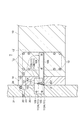
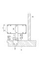
- FIG. 1 is a cross-sectional view showing an outer wall structure according to this embodiment.
- the outer wall structure according to the present embodiment forms an outer wall by connecting a PC [Precast Concrete] plate 20 formed in advance in a factory or the like to the housing 10.
- a fastener member 100 for connecting the plates 20 is provided.
- the PC board 20 is a member corresponding to the panel body in the claims, and constitutes at least a part of the outer wall.
- the panel body in a claim is not restricted to a concrete PC board.
- the panel body includes a resin panel (for example, a heat insulating panel using expanded polystyrene).
- the housing 10 is a concrete housing that constitutes the floor of the building. Inside the housing 10, a unit rebar 11 having a main reinforcement 12 and a reinforcement 13 is arranged.
- the PC board 20 constitutes a part of the outer wall by being joined to other PC boards in the vertical direction and the horizontal direction.
- the PC board 20 and the other PC board 21 are joined to each other by a fixing bracket (not shown), and a sealing material 22, a backup material 23, and a gasket 24 are disposed in the gap.
- a heat insulating material 14 made of rock wool, polystyrene foam or the like is filled between the housing 10 and the PC board 20.
- an appropriate filler buffer material
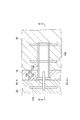
- FIG. 2 is a plan view showing the fastener member 100
- FIG. 3 (a) is a side view showing the fastener member 100 (a side view seen from the housing 10 side).
- 3B is a cross-sectional view taken along line IIIb-IIIb in FIG. 2
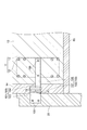
- FIG. 4 is a cross-sectional view taken along line IV-IV in FIG.
- illustration of Kanzashi muscles 105 and 108 to be described later is omitted.
- the fastener member 100 shown in FIGS. 1 to 4 is a member formed of a metal such as stainless steel or plated steel.
- the fastener member 100 may be formed from a ceramic other than a metal, and may be subjected to various coatings.
- the fastener member 100 includes a first fastener 101 embedded in the PC board 20 and a second fastener 102 embedded in the housing 10.
- the first fastener 101 is a plate-like member including a main body portion 103 embedded (fixed) in the PC plate 20 and a head portion 104 protruding in a hook shape toward the housing 10.
- a main body portion 103 embedded (fixed) in the PC plate 20 and a head portion 104 protruding in a hook shape toward the housing 10.
- two Kanzashi muscles 105 are arranged penetrating in the horizontal direction, and the pull-out strength of the first fastener 101 is increased.
- a first groove A for fitting with the second fastener 102 is formed between the main body 103 and the head 104.
- the first groove A is a groove that opens downward, and is fitted to the second fastener 102 in the vertical direction.
- the first groove A is formed from a bottom surface (first bottom surface) 110 and a side surface 111.
- the side surface 111 has a pair of narrowest surfaces (first narrowest surfaces) 112A and 112B having the narrowest width and other spaced surfaces (first spaced surfaces) 113A and 113B.
- the pair of narrowest surfaces 112A and 112B are surfaces formed so as to sandwich the second fastener 102 to be fitted.
- the pair of narrowest surfaces 112 ⁇ / b> A and 112 ⁇ / b> B are in contact with the second fastener 102 and sandwich the second fastener 102.
- the pair of narrowest surfaces 112 ⁇ / b> A and 112 ⁇ / b> B are side surfaces that are continuous with the bottom surface 110 in the first groove A, and are formed along the bottom surface 110.
- the second fastener 102 fitted in the first groove A moves in the front-rear direction (the direction in which the housing 10 and the PC plate 20 face each other) and the upper direction by contacting the pair of narrowest surfaces 112A and 112B and the bottom surface 110. It is regulated.
- the pair of narrowest surfaces 112A and 112B and the second fastener 102 do not always have to be in contact with each other, and a gap may exist.
- the separation surfaces 113A and 113B are surfaces formed so as to be separated from the second fastener 102 as compared with the narrowest surfaces 112A and 112B. That is, the separation surface 113A on the PC board 20 side is formed so as to be farther from the second fastener 102 than the narrowest surface 112A on the same side, and the separation surface 113B on the housing 10 side is the narrowest surface on the same side. It is formed so as to be separated from the second fastener 102 as compared with 112B.
- the separation surfaces 113A and 113B are formed so as to be separated from the second fastener 102 as the distance from the narrowest surfaces 112A and 112B increases (that is, as the distance from the bottom surface 110 of the first groove A increases).
- the separation surfaces 113A and 113B are formed as smooth curved surfaces that move away from the second fastener 102 as the distance from the narrowest surfaces 112A and 112B increases.
- the separation surfaces 113A and 113B include all the surfaces of the side surface 111 that are separated from the second fastener 102 (that is, the face plate 107) as compared with the narrowest surfaces 112A and 112B. That is, the side surface 111 is divided into the narrowest surfaces 112A and 112B and the separation surfaces 113A and 113B.
- the narrowest surfaces 112A and 112B and the separating surfaces 113A and 113B do not need to be distinguished by shape.
- the narrowest surfaces 112A and 112B are the portions that are in contact with the second fastener 102 to be fitted (or the portion where the second fastener 102 moves and strikes the front and rear direction).
- the other surfaces can be the separation surfaces 113A and 113B.
- the separation surfaces 113A and 113B do not have to be a single surface, and may be composed of a plurality of flat surfaces, curved surfaces, or the like, and may have irregularities.
- the second fastener 102 is provided with a channel-like (cross-sectionally U-shaped) main body 106 embedded (fixed) in the housing 10, and at the tip of the main body 106.
- This is a member composed of the face plate 107.
- two kanzashi muscles 108 are arranged penetrating in the horizontal direction in order to increase the pullout strength of the second fastener 102.
- the face plate 107 is a plate-like flange portion provided substantially parallel to the PC plate 20. As shown in FIG. 3A, the face plate 107 has a second groove B into which the first fastener 101 is fitted.
- the second groove B is a groove that opens upward at the approximate center of the face plate 107, and is fitted so as to be engaged with the first groove A of the first fastener 101.
- the face plate 107 is fitted to the plate-like first fastener 101 so as to form a cross when viewed from above (see FIG. 2).
- the second groove B is formed from a bottom surface (second bottom surface) 120 and a side surface 121.
- the side surface 121 has a pair of narrowest surfaces (second narrowest surfaces) 122A and 122B having the narrowest width and other spaced surfaces (second spaced surfaces) 123A and 123B.
- the pair of narrowest surfaces 122A and 122B are surfaces formed so as to sandwich the first fastener 101 to be fitted.
- the pair of narrowest surfaces 122 ⁇ / b> A and 122 ⁇ / b> B are in contact with the first fastener 101 and sandwich the first fastener 101.
- the pair of narrowest surfaces 122A and 122B are side surfaces that are continuous with the bottom surface 120 of the second groove B, and are formed along the bottom surface 120.
- the first fastener 101 fitted in the second groove B is in contact with the pair of narrowest surfaces 122A and 122B and the bottom surface 120 to restrict lateral movement (horizontal direction parallel to the PC plate 20) and downward movement.
- the pair of narrowest surfaces 122A and 122B and the first fastener 101 do not always have to be in contact with each other, and a gap may exist.
- the separation surfaces 123A and 123B are formed so as to be separated from the first fastener 101 as compared with the pair of narrowest surfaces 122A and 122B. That is, the separation surface 123A on the PC board 20 side is formed so as to be separated from the first fastener 101 compared to the narrowest surface 122A on the same side, and the separation surface 123B on the housing 10 side is the narrowest surface on the same side. It is formed so as to be separated from the first fastener 101 as compared with 122B.
- the separation surfaces 123A and 123B are formed so as to be separated from the first fastener 101 as the distance from the narrowest surfaces 122A and 122B increases (that is, as the distance from the bottom surface 120 of the second groove B increases).
- the separation surfaces 123A and 123B are formed as smooth curved surfaces that move away from the first fastener 101 as the distance from the narrowest surfaces 122A and 122B increases.
- the separation surfaces 123A and 123B include all of the side surfaces 121 that are separated from the first fastener 101 as compared with the narrowest surfaces 122A and 122B. That is, the side surface 121 is divided into the narrowest surfaces 122A and 122B and the separation surfaces 123A and 123B.
- the narrowest surfaces 122A and 122B and the separation surfaces 123A and 123B do not need to be distinguished by shape.
- the narrowest surfaces 122A, 122B are the portions that are in contact with the first fastener 101 to be fitted (or the portion where the first fastener 101 moves and abuts in the lateral direction).
- the other surfaces can be the separation surfaces 123A and 123B.
- the separation surfaces 123A and 123B do not have to be a single surface, and may be composed of a plurality of flat surfaces, curved surfaces, or the like, and may have unevenness.
- the fastener member 100 having the outer wall structure according to the present embodiment described above the first fastener fixed to the PC plate 20 and the second fastener fixed to the housing 10 are fitted to each other.
- the housing 10 is connected, and the PC board 20 can be supported with respect to the housing 10.
- the plate-like first fastener 101 and the face plate 107 of the second fastener 102 are fitted to each other, so that the fastener member 100 is fitted as compared with the case where a box-like or block-like fastener is used.
- the contact area of the part can be reduced, and the heat transfer between the PC board 20 and the housing 10 through the fastener member 100 can be reduced.
- the fastener member 100 is provided with separation surfaces 113A, 113B, 123A, and 123B that are separated from the mating fasteners in the first groove A and the second groove B that are engaged with each other, and the narrowest surfaces 112A, 112B, 122A,
- the first fastener 101 and the second fastener 102 are moved in the disengagement direction (that is, the first fastener 101 moves upward and the second fastener 102 moves downward). Since the fasteners 101 and 102 are also allowed to swing around the pair of narrowest surfaces 112A, 112B, 122A, and 122B as a fulcrum, the PC plate 20 is moved (locked) with respect to the housing 10 during an earthquake. It is possible to absorb the displacement by allowing. This contributes to improving the earthquake resistance of the outer wall structure.
- the separation surfaces 113A, 113B, 123A, and 123B are gradually separated away from the narrowest surfaces 112A, 112B, 122A, and 122B. Since no large step is formed in the grooves A and B, the movement due to the locking of the PC plate 20 is prevented from being caught by the step or the like in an earthquake or the like. This is advantageous in improving the seismic resistance of the outer wall structure because it allows smooth displacement tolerance due to rocking.
- the pair of narrowest surfaces 112A, 112B, 122A, 122B are formed along the bottom surfaces 110, 120, respectively.
- the contact area between the first fastener 101 and the second fastener 102 can be further reduced, so that the space between the PC plate 20 and the casing 10 through the fastener member can be reduced. This is advantageous for reducing heat transfer.
- the outer wall construction method includes a PC board arranging step (panel body arranging step) for arranging the PC plate 20, a bar arranging step for arranging the rods, a fastener arranging step for arranging the second fastener 102, and It has at least a placing step for placing concrete for the frame.
- a PC board arranging step is performed.
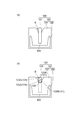
- Fig.5 (a) is a figure explaining the PC board arrangement
- a new PC board 20 is arranged with respect to the existing PC board (existing structure) 40 constituting the lower outer wall.
- the PC board 20 is arranged with respect to an existing structure such as a foundation.
- the PC plate 20 is a concrete plate member molded in advance at a factory or the like, and a pair of first fasteners 101 is already embedded in the upper part.
- a pair of lower load receiving fasteners 50 for temporarily receiving the load of the PC plate 20 and a pair of lower anti-fretting fasteners 51 for preventing the PC plate 20 from flaking are provided at the lower part of the PC plate 20.
- the PC board 20 may be previously formed with an opening for a window, a connection projection for a balcony, or the like.
- FIG.5 (b) is a figure which shows the state which has arrange
- the PC board 20 is arranged so as to continue to the lower PC board 40.
- the lower part of the PC board 20 is supported by fixing a lower load receiving fastener 50 and a lower anti-fretting fastener 51 to connection fittings 52 and 53 provided on the upper part of the PC board 40.
- a rod-like support member 54 is disposed obliquely.
- the PC column member may support the PC plate 20 instead of the rod-shaped support member 54.
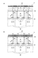
- Fig.6 (a) is a figure for demonstrating a bar arrangement process.
- the frame 60 for the frame is assembled with the PC plate 20 and the unit reinforcing bars 11 are arranged.
- the unit reinforcing bar 11 is configured by assembling reinforcing bars in a unit shape in advance at a factory or the like. Adoption of the unit rebar 11 is also advantageous in the on-site bar arrangement.
- FIG. 6B is a diagram illustrating a state in which the bar arrangement is arranged in the bar arrangement process.
- the unit reinforcing bars 11 are arranged on the mold 60 so as to be at the same height as the first fastener 101 of the PC plate 20.
- the unit reinforcing bars 11 can be arranged simply by lifting them with a crane or the like and lowering them to a predetermined position.
- FIG. 7 is a view for explaining a fastener arranging step.
- the second fastener 102 is arranged so as to be fitted to the first fastener 101 embedded in the PC board 20.
- the second fastener 102 is disposed so that a part of the main body portion 106 enters the unit rebar 11.
- the second fastener 102 is temporarily fixed in a state of being fitted to the first fastener 101.
- the second fastener 102 is temporarily fixed by attaching a temporary fixing band 70 to a fitting portion (a portion where the first groove A and the second groove B are engaged) with the first fastener 101.
- a band having elasticity can be adopted as the temporarily fixing band 70, but an aspect in which a band having no elasticity is wound and temporarily fixed may be used.
- the temporary fixing band 70 may be removed after the completion of construction, or may not be removed. In the case where it is not removed even after the completion of construction, it is preferable that the strength of temporary fixing by the temporary fixing band 70 does not hinder the locking of the PC board 20.
- temporary fixing is performed using the temporary fixing band 70, but the temporary fixing method is not limited to that using the temporary fixing band 70.
- temporary fixing may be performed by arranging a temporary fixing pin that penetrates the fitting portion of the first fastener 101 and the second fastener 102.
- the temporarily fixing pin has a strength that does not hinder the locking of the PC board 20 (that is, a strength at which the temporarily fixing pin is deformed or broken when locking is necessary).
- FIG. 8 is a diagram for explaining the placing process.
- concrete is placed so as to embed a part of the main body portion 106 of the second fastener 102 and the unit rebar 11.
- the heat insulating material 14 is attached to the first fastener 101 side of the PC board 20 before placing concrete.
- most of the heat insulating material 14 is attached to the PC board 20 at a factory, and only a portion corresponding to the first fastener 101 may be attached on site.
- the concrete placed in the mold 60 is compacted and finished, and after curing, the concrete hardens and exhibits strength, thereby forming the frame 10.
- the second fastener 102 is in a state in which a part of the main body portion 106 is embedded in the housing 10.
- the PC board 20 can be supported by the housing 10 via the second fastener 102 and the first fastener 101 to be fitted.
- the temporary lower load receiving fastener 50 and the support member 54 are removed so that the PC board 20 is supported by the housing 10 and the outer wall is constructed.
- the PC plate 20 is disposed first, the second fastener 102 is disposed so as to be fitted to the first fastener 101 of the PC plate 20, and then the second fastener.
- the structure of the housing 10 and the connection of the PC board 20 and the housing 10 can be performed at a time, and the work efficiency at the site is improved.
- the outer wall construction method since the main body portion 106 of the second fastener 102 is embedded in the housing 10 while being fitted to the first fastener 101, the second fastener 102 fixed to the housing 10 side and the first fastener Positioning with the fastener 101 becomes unnecessary, and the work is simplified. Moreover, according to this outer wall construction method, since the second fastener 102 is disposed after the bar arrangement process, the second fastener 102 does not interfere with the bar arrangement, and the bar arrangement work can be efficiently performed. In particular, when a unit reinforcing bar is employed, it can be arranged simply by lifting and arranging the unit reinforcing bar, so that the construction period for constructing the outer wall can be greatly shortened.
- the fitting portion of the first fastener 101 and the second fastener 102 is temporarily fixed in the fastener arranging step, so that the second fastener 102 is temporarily fixed to the reinforcing bar.
- the temporary fixing work becomes easy.
- the fitting portion of the first fastener 101 and the second fastener 102 is temporarily fixed, even if the second fastener 102 moves due to the influence of concrete placement or the like, the fitting with the first fastener 101 is displaced. Therefore, the PC board 20 and the housing 10 can be appropriately connected.
- the heat transfer between the PC board 20 and the housing 10 through the fastener member 100 can be reduced by employing the fastener member 100 having the above-described configuration.
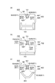
- FIG. 9A is a cross-sectional view showing a first modification of the fastener member.
- the fastener member 200 shown in FIG. 9A differs from the fastener member 100 shown in FIG. 4 only in the shape of the first groove A1.
- the first groove A1 is different from the first groove A shown in FIG. 4 in that the main body 203 side of the first fastener 201 of the side surface 211 is a single plane. That is, no separation surface is formed on the side surface 211 on the main body 203 side.
- the plane as a whole corresponds to the narrowest surface 212A, and sandwiches the second fastener 102 in a pair with the opposite narrowest surface 212B.
- the configuration in which the left and right sides 211 are switched that is, the surface on the main body 203 side of the first fastener 201 and the surface on the head 204 side of the side surface 211.
- a configuration in which is replaced is also included in the present invention.
- FIG. 9B is a cross-sectional view showing a second modification of the fastener member.
- the fastener member 300 shown in FIG. 9B is different from the fastener member 100 shown in FIG. 4 only in the shape of the first groove A2.
- the first groove A2 of the fastener member 300 has a pair of narrowest surfaces 312A and 312B and separation surfaces 313A and 313B that form the side surface 311 as compared with the first groove A shown in FIG.
- the present invention includes a case where the side surface 311 does not have a curved surface and is constituted by a plurality of planes.
- FIG. 9C is a cross-sectional view showing a third modification of the fastener member.
- the fastener member 400 shown in FIG. 9C is different from the fastener member 100 shown in FIG. 4 only in the shape of the first groove A3 and the cross-sectional shape of the face plate 407 of the second fastener 402.
- the first groove A3 is different from the first groove A shown in FIG. 4 in that a pair of narrowest surfaces 412A and 412B are formed in the middle of the first groove A3. Yes. That is, the pair of narrowest surfaces 412A and 412B are not formed along the bottom surface 410 of the first groove A3. Further, the first groove A3 has a pair of narrowest surfaces 412A and 412B constituting the side surface 411, bottom side separation surfaces 413A and 413B, and opening side separation compared to the first groove A shown in FIG. Another difference is that the surfaces 414A and 414B are each composed of a plane. Such a configuration shown in FIG. 9C is also included in the present invention.
- the taper becomes closer to the bottom surface 410 of the first groove A3.
- the fitting portion (the center upper end portion) of the face plate 407 into a trapezoidal cross section so that the surface is in contact with the bottom surface 410 of the first groove A3 (that is, the bottom surface of the second groove) is narrowed. The area can be reduced and the heat transfer can be further reduced. It is not essential to form the face plate 407 in this way.
- FIG. 9D is a cross-sectional view showing a fourth modification of the fastener member.
- the fastener member 500 shown in FIG. 9D is configured by forming the side surface 411 of the first groove A3 of the fastener member 400 shown in FIG. 9C described above from a curved surface.
- the pair of narrowest surfaces 512A and 512B constituting the side surface 511 of the first groove A4 the separation surfaces 513A and 513B on the bottom side, and the separation surfaces 514A and 514B on the opening side are formed from curved surfaces.
- the separation surfaces 513A and 513B on the bottom side, and the separation surfaces 514A and 514B on the opening side are formed from curved surfaces.
- the face plate 507 in contact with the bottom surface 510 of the first groove A4.
- the fitting portion By forming the fitting portion to be rounded, the contact surface with the bottom surface 510 of the first groove A4 (that is, the bottom surface of the second groove) can be narrowed to reduce the contact area, and heat transfer Can be further reduced. It is not essential to form the face plate 507 in this way. Further, the face plate 507 shown in FIG. 9D and the face plate 407 shown in FIG. 9C can be used interchangeably.
- one side surface is formed from one plane as shown in FIG. 9A, and the side surface forms a separation surface.
- the case where it does not exist is also included in the present invention.
- FIG. 10A is a cross-sectional view showing a fifth modification of the fastener member.
- the fastener member 600 shown in FIG. 10A differs from the fastener member 100 shown in FIG. 3B only in the shape of the second groove B1 and the shape of the main body portion 606 of the second fastener 602.
- the second groove B1 of the fastener member 600 has a pair of narrowest surfaces 622A, 622B and a separation surface 623A, which constitute the side surface 621, as compared with the second groove B shown in FIG. Only the point that 623B is a plane is different. That is, the case where the side surface 621 does not have a curved surface and is configured by a plurality of planes is included in the present invention.
- the shape of the main body 606 of the second fastener 602 is not necessarily a channel shape, and a plate-like shape can also be adopted. In this case, a kansai streak that penetrates in the vertical direction may be arranged.
- FIG. 10B is a cross-sectional view showing a sixth modification of the fastener member.
- the fastener member 700 shown in FIG. 10 (b) has the shape of the second groove B2, the shape of the main body 606 of the second fastener 602, and the first fastener 701. Only the shape of the fitting part is different.
- the second groove B2 of the fastener member 700 has a pair of narrowest surfaces 722A and 722B formed in the middle of the second groove B2 as compared to the second groove B shown in FIG. And the point that the side surface 721 is composed of a plurality of planes is different. That is, the pair of narrowest surfaces 722A and 722B is not formed along the bottom surface 720 of the second groove B2, but the pair of narrowest surfaces 722A and 722B, the bottom side separation surfaces 723A and 723B, and the opening side
- the present invention also includes a case in which the separation surfaces 724A and 724B are each composed of a flat surface.
- the taper becomes closer to the bottom surface 720 of the second groove B2.
- the fitting portion of the first fastener 701 into a trapezoidal cross section so as to become, the surface that contacts the bottom surface 720 of the second groove B2 (that is, the bottom surface of the first groove) is narrowed to reduce the contact area Heat transfer can be further reduced. Note that it is not essential to form the first fastener 701 in this way.
- the main body 706 of the second fastener 702 may have an H-shaped cross section.
- FIG. 10C is a cross-sectional view showing a seventh modification of the fastener member.
- a fastener member 800 shown in FIG. 10 (c) is configured by forming the side surface 721 of the second groove B2 of the fastener member 700 shown in FIG. 10 (b) described above from a curved surface.
- the present invention includes the case where the pair of narrowest surfaces 822A and 822B, the bottom-side separation surfaces 823A and 823B, and the opening-side separation surfaces 824A and 824B that form the side surface 821 of the second groove B3 are curved surfaces. include.
- the fitting portion of the fastener 801 so as to have a roundness, the surface that contacts the bottom surface 820 of the second groove B3 (that is, the bottom surface of the first groove) can be narrowed to reduce the contact area. Heat transfer can be further reduced. Note that it is not essential to form the first fastener 801 in this way.
- the main body 806 of the second fastener 802 may have a substantially V-shaped cross section.
- FIG. 11A is a cross-sectional view showing an eighth modification of the fastener member.
- the fastener member 900 shown in FIG. 11A differs from the fastener member 100 shown in FIG. 2 only in the shape of the second groove B4.
- the side surface 922 of the second groove B4 is formed in a trapezoidal shape when viewed from above, and only the tip of the trapezoid is in contact with the first fastener 101. That is, the trapezoidal tip portion of the side surface 922 viewed from above corresponds to the narrowest surfaces 922A and 922B. The portions other than the tip portion correspond to the separation surfaces 923A and 923B that are separated from the first fastener 101. According to such a configuration, since the contact area between the first fastener 101 and the second fastener 902 can be further reduced, heat transfer can be further reduced.
- FIG. 11B is a cross-sectional view showing a ninth modification of the fastener member.
- the fastener member 1000 shown in FIG. 11B is different from the fastener member 100 shown in FIG. 2 only in the shape of the second groove B5.
- the side surface 1022 of the second groove B5 is formed to be semicircular when viewed from above, and only the semicircular tip is in contact with the first fastener 101. That is, of the side surface 1022, the semicircular tip viewed from above corresponds to the narrowest surfaces 1022A and 1022B. The portions other than the tip correspond to the separation surfaces 1023A and 1023B which are separated from the first fastener 101. According to such a configuration, since the contact area between the first fastener 101 and the second fastener 1002 can be further reduced, heat transfer can be further reduced.
- the side surface 111 of the first groove A of the first fastener 101 may be formed in a trapezoidal shape or a semicircular shape when viewed from below. Thereby, reduction of the further heat transfer is attained.
- FIGS. 9 to 11 described above can be combined with each other. That is, any of the modifications shown in FIGS. 10 (a) to 10 (c) may be combined with the modification shown in FIG. 9 (a), and further, FIG. 11 (a) or FIG. ) May be used in combination. The same applies to FIGS. 9B to 9D.
- the shape of the contact portion of the fastener is appropriately selected according to the load applied to the portion. That is, durability can be secured as a surface contact (for example, contact by a flat surface) in a portion with a large load, and a contact area can be reduced as a point contact (for example, contact by a curved surface).
- the present invention is not limited to the above-described modification.
- the first fastener and the second fastener may be used interchangeably. That is, the aspect which fixes a 1st fastener with respect to a housing and fixes a 2nd fastener with respect to a PC board may be sufficient. In this case, it arrange
- various shapes can be employed for the first fastener and the second fastener.
- the fastener member has the above-described fitting structure (the first fastener and the second fastener described above, the first groove and It is only necessary to have a structure in which the second grooves are fitted to each other.
- the remaining fastener members are not limited to the above-described fitting structure.
- the face plate of the second fastener on the housing side is a rectangular plate that does not have a groove, and this rectangular plate serves as the first groove of the first fastener.
- the structure which fits may be sufficient. In this case, the horizontal movement of the first fastener can be slid on the face plate without being restricted, and the horizontal displacement of the PC plate due to locking can be partially allowed.
- the present invention can be used for a fastener member that can reduce heat transfer between the panel body and the casing, an outer wall structure including the fastener member, and an outer wall construction method.
Landscapes
- Engineering & Computer Science (AREA)
- Architecture (AREA)
- Physics & Mathematics (AREA)
- Electromagnetism (AREA)
- Civil Engineering (AREA)
- Structural Engineering (AREA)
- Load-Bearing And Curtain Walls (AREA)
- Finishing Walls (AREA)
Abstract
La présente invention concerne un élément de fixation (100) qui accouple un panneau PC (20) et un cadre (10). L'élément de fixation (100) comprend un premier élément de fixation de plateforme (101) fixé à un élément parmi le panneau PC (20) et le cadre (10) et dans lequel une première rainure (A) pour l'installation est formée, et un second élément de fixation (102) qui comporte un corps (106), fixé à l'autre élément parmi le panneau PC (20) et le cadre (10), et une plaque frontale (107) dans laquelle une seconde rainure (B) est formée pour l'installation avec la première rainure (A). La première rainure (A) comporte une paire de premières faces les plus étroites (112A, 112B), des premières faces de séparation (113A, 113B), et une première face inférieure (110), et la seconde rainure (B) comporte une paire de secondes faces les plus étroites (122A, 122B), des secondes faces de séparation (123A, 123B), et une seconde face inférieure (120).
Priority Applications (3)
| Application Number | Priority Date | Filing Date | Title |
|---|---|---|---|
| CN201280073947.4A CN104350218B (zh) | 2012-07-26 | 2012-07-26 | 紧固部件、具备紧固部件的外壁结构以及外壁施工方法 |
| JP2014526670A JP5706589B2 (ja) | 2012-07-26 | 2012-07-26 | ファスナー部材、ファスナー部材を備えた外壁構造、及び外壁施工方法 |
| PCT/JP2012/068969 WO2014016936A1 (fr) | 2012-07-26 | 2012-07-26 | Éléments de fixation, structures murales extérieures comprenant des éléments de fixation, et procédé de construction pour murs extérieurs |
Applications Claiming Priority (1)
| Application Number | Priority Date | Filing Date | Title |
|---|---|---|---|
| PCT/JP2012/068969 WO2014016936A1 (fr) | 2012-07-26 | 2012-07-26 | Éléments de fixation, structures murales extérieures comprenant des éléments de fixation, et procédé de construction pour murs extérieurs |
Publications (1)
| Publication Number | Publication Date |
|---|---|
| WO2014016936A1 true WO2014016936A1 (fr) | 2014-01-30 |
Family
ID=49996771
Family Applications (1)
| Application Number | Title | Priority Date | Filing Date |
|---|---|---|---|
| PCT/JP2012/068969 Ceased WO2014016936A1 (fr) | 2012-07-26 | 2012-07-26 | Éléments de fixation, structures murales extérieures comprenant des éléments de fixation, et procédé de construction pour murs extérieurs |
Country Status (3)
| Country | Link |
|---|---|
| JP (1) | JP5706589B2 (fr) |
| CN (1) | CN104350218B (fr) |
| WO (1) | WO2014016936A1 (fr) |
Citations (4)
| Publication number | Priority date | Publication date | Assignee | Title |
|---|---|---|---|---|
| JPS5934350A (ja) * | 1982-08-20 | 1984-02-24 | 太平洋セメント株式会社 | 壁板取り付け装置 |
| JPS6164941A (ja) * | 1984-09-04 | 1986-04-03 | ミサワホ−ム株式会社 | 壁パネルの取付構造 |
| JPS63169608U (fr) * | 1987-04-23 | 1988-11-04 | ||
| JPH0347351A (ja) * | 1989-07-14 | 1991-02-28 | Shimizu Corp | Pc版による壁構築方法 |
Family Cites Families (4)
| Publication number | Priority date | Publication date | Assignee | Title |
|---|---|---|---|---|
| DE3506140A1 (de) * | 1984-12-22 | 1986-06-26 | Herbert 8400 Regensburg Utner | Plattenverankerungssystem |
| CN1295407C (zh) * | 2004-10-10 | 2007-01-17 | 刘超 | 陶石连接件及连接方法 |
| CN101725199B (zh) * | 2009-12-07 | 2012-08-08 | 德国陶瓷克雷默和鲍尔股份公司 | 一种陶板干挂系统 |
| CN202299054U (zh) * | 2011-10-28 | 2012-07-04 | 沈阳远大铝业工程有限公司 | 一种混凝土板幕墙构件 |
-
2012
- 2012-07-26 WO PCT/JP2012/068969 patent/WO2014016936A1/fr not_active Ceased
- 2012-07-26 CN CN201280073947.4A patent/CN104350218B/zh not_active Expired - Fee Related
- 2012-07-26 JP JP2014526670A patent/JP5706589B2/ja not_active Expired - Fee Related
Patent Citations (4)
| Publication number | Priority date | Publication date | Assignee | Title |
|---|---|---|---|---|
| JPS5934350A (ja) * | 1982-08-20 | 1984-02-24 | 太平洋セメント株式会社 | 壁板取り付け装置 |
| JPS6164941A (ja) * | 1984-09-04 | 1986-04-03 | ミサワホ−ム株式会社 | 壁パネルの取付構造 |
| JPS63169608U (fr) * | 1987-04-23 | 1988-11-04 | ||
| JPH0347351A (ja) * | 1989-07-14 | 1991-02-28 | Shimizu Corp | Pc版による壁構築方法 |
Also Published As
| Publication number | Publication date |
|---|---|
| JPWO2014016936A1 (ja) | 2016-07-07 |
| JP5706589B2 (ja) | 2015-04-22 |
| CN104350218A (zh) | 2015-02-11 |
| CN104350218B (zh) | 2016-12-07 |
Similar Documents
| Publication | Publication Date | Title |
|---|---|---|
| US20100071315A1 (en) | Composite concrete column and construction method using the same | |
| JP4992479B2 (ja) | 柱部材、ufc製プレキャスト型枠および当該ufc製プレキャスト型枠を用いた柱部材の耐震補強方法 | |
| KR101255464B1 (ko) | 캡 플레이트를 활용한 단부 연속화 데크 플레이트 시스템 | |
| KR101608944B1 (ko) | 건축용 스틸 거푸집 폼 및 이를 사용한 건축 구조물 형성 공법 | |
| KR101533576B1 (ko) | 반채움 pc 트러스보강재 합성보 | |
| KR20200067408A (ko) | 두께 가변형 이중벽체 및 그 시공방법 | |
| KR101302520B1 (ko) | 콘크리트 벽체 시공구조 | |
| KR20120042237A (ko) | 스트립 형태의 강판 부재를 이용한 기존 벽체의 내진 성능 개선 방법 | |
| US10400450B2 (en) | Deck panel for construction | |
| KR101645525B1 (ko) | 트윈월 및 트윈월을 이용하여 제작된 트윈월 구조체의 시공방법 | |
| KR101160763B1 (ko) | 다수 개의 캡 플레이트를 갖는 데크 플레이트를 이용한 합성보 | |
| KR101655330B1 (ko) | 단부합성 강재빔을 이용하여 제작된 라멘구조물 및 그 시공방법 | |
| KR100796216B1 (ko) | 건축물의 콘크리트 복합보 | |
| JP5706589B2 (ja) | ファスナー部材、ファスナー部材を備えた外壁構造、及び外壁施工方法 | |
| KR101191545B1 (ko) | 다수 개의 캡 플레이트를 갖는 데크 플레이트 | |
| KR101240581B1 (ko) | 십자형 정착판지지판을 이용한 단부지지체, 이를 구비한 프리스트레스트 강합성빔 및 프리스트레스트 강합성빔 시공방법 | |
| JP4728453B1 (ja) | 主桁の連続化構造 | |
| KR101466683B1 (ko) | 노후 철근콘크리트 보-기둥 구조물을 위하여 피씨부재를 활용한 리모델링 내진보강 접합구조 및 이를 이용한 건물 리모델링 시공 방법 | |
| JP5904052B2 (ja) | 薄板軽量形鋼造の上下階の連結構造 | |
| CN109840384B (zh) | 一种兼具承重与耗能双重功能的分段式钢筋混凝土连梁的设计方法 | |
| CN221837798U (zh) | 一种装配式减震复合填充墙连接构造 | |
| KR101171061B1 (ko) | 기둥의 수직결합이 용이한 난방배관 일체형 경량합성바닥판이 구비된 모듈러 유닛 | |
| CN203947685U (zh) | 预制外墙板的剪力键槽盒 | |
| KR101797960B1 (ko) | 중립축 상승부재를 갖는 강재보 및 이를 이용한 합성보 | |
| KR101023175B1 (ko) | 프리플렉스 합성보 제작방법 및 이를 이용한 부분 프리플렉스 연속합성보 |
Legal Events
| Date | Code | Title | Description |
|---|---|---|---|
| 121 | Ep: the epo has been informed by wipo that ep was designated in this application |
Ref document number: 12881770 Country of ref document: EP Kind code of ref document: A1 |
|
| ENP | Entry into the national phase |
Ref document number: 2014526670 Country of ref document: JP Kind code of ref document: A |
|
| NENP | Non-entry into the national phase |
Ref country code: DE |
|
| 122 | Ep: pct application non-entry in european phase |
Ref document number: 12881770 Country of ref document: EP Kind code of ref document: A1 |