WO2014017221A1 - 天井走行車システム及び天井走行車システムでの移載制御方法 - Google Patents
天井走行車システム及び天井走行車システムでの移載制御方法 Download PDFInfo
- Publication number
- WO2014017221A1 WO2014017221A1 PCT/JP2013/066700 JP2013066700W WO2014017221A1 WO 2014017221 A1 WO2014017221 A1 WO 2014017221A1 JP 2013066700 W JP2013066700 W JP 2013066700W WO 2014017221 A1 WO2014017221 A1 WO 2014017221A1
- Authority
- WO
- WIPO (PCT)
- Prior art keywords
- overhead traveling
- traveling vehicle
- track
- sensor
- local
- Prior art date
- Legal status (The legal status is an assumption and is not a legal conclusion. Google has not performed a legal analysis and makes no representation as to the accuracy of the status listed.)
- Ceased
Links
Images




Classifications
-
- B—PERFORMING OPERATIONS; TRANSPORTING
- B65—CONVEYING; PACKING; STORING; HANDLING THIN OR FILAMENTARY MATERIAL
- B65G—TRANSPORT OR STORAGE DEVICES, e.g. CONVEYORS FOR LOADING OR TIPPING, SHOP CONVEYOR SYSTEMS OR PNEUMATIC TUBE CONVEYORS
- B65G1/00—Storing articles, individually or in orderly arrangement, in warehouses or magazines
- B65G1/02—Storage devices
- B65G1/04—Storage devices mechanical
-
- H—ELECTRICITY
- H10—SEMICONDUCTOR DEVICES; ELECTRIC SOLID-STATE DEVICES NOT OTHERWISE PROVIDED FOR
- H10P—GENERIC PROCESSES OR APPARATUS FOR THE MANUFACTURE OR TREATMENT OF DEVICES COVERED BY CLASS H10
- H10P72/00—Handling or holding of wafers, substrates or devices during manufacture or treatment thereof
- H10P72/30—Handling or holding of wafers, substrates or devices during manufacture or treatment thereof for conveying, e.g. between different workstations
- H10P72/32—Handling or holding of wafers, substrates or devices during manufacture or treatment thereof for conveying, e.g. between different workstations between different workstations
- H10P72/3221—Overhead conveying
-
- B—PERFORMING OPERATIONS; TRANSPORTING
- B65—CONVEYING; PACKING; STORING; HANDLING THIN OR FILAMENTARY MATERIAL
- B65G—TRANSPORT OR STORAGE DEVICES, e.g. CONVEYORS FOR LOADING OR TIPPING, SHOP CONVEYOR SYSTEMS OR PNEUMATIC TUBE CONVEYORS
- B65G1/00—Storing articles, individually or in orderly arrangement, in warehouses or magazines
- B65G1/02—Storage devices
- B65G1/04—Storage devices mechanical
- B65G1/0407—Storage devices mechanical using stacker cranes
-
- B—PERFORMING OPERATIONS; TRANSPORTING
- B65—CONVEYING; PACKING; STORING; HANDLING THIN OR FILAMENTARY MATERIAL
- B65G—TRANSPORT OR STORAGE DEVICES, e.g. CONVEYORS FOR LOADING OR TIPPING, SHOP CONVEYOR SYSTEMS OR PNEUMATIC TUBE CONVEYORS
- B65G1/00—Storing articles, individually or in orderly arrangement, in warehouses or magazines
- B65G1/02—Storage devices
- B65G1/04—Storage devices mechanical
- B65G1/0407—Storage devices mechanical using stacker cranes
- B65G1/0414—Storage devices mechanical using stacker cranes provided with satellite cars adapted to travel in storage racks
-
- B—PERFORMING OPERATIONS; TRANSPORTING
- B66—HOISTING; LIFTING; HAULING
- B66C—CRANES; LOAD-ENGAGING ELEMENTS OR DEVICES FOR CRANES, CAPSTANS, WINCHES, OR TACKLES
- B66C13/00—Other constructional features or details
- B66C13/18—Control systems or devices
-
- B—PERFORMING OPERATIONS; TRANSPORTING
- B66—HOISTING; LIFTING; HAULING
- B66C—CRANES; LOAD-ENGAGING ELEMENTS OR DEVICES FOR CRANES, CAPSTANS, WINCHES, OR TACKLES
- B66C19/00—Cranes comprising trolleys or crabs running on fixed or movable bridges or gantries
-
- H—ELECTRICITY
- H10—SEMICONDUCTOR DEVICES; ELECTRIC SOLID-STATE DEVICES NOT OTHERWISE PROVIDED FOR
- H10P—GENERIC PROCESSES OR APPARATUS FOR THE MANUFACTURE OR TREATMENT OF DEVICES COVERED BY CLASS H10
- H10P72/00—Handling or holding of wafers, substrates or devices during manufacture or treatment thereof
- H10P72/06—Apparatus for monitoring, sorting, marking, testing or measuring
- H10P72/0606—Position monitoring, e.g. misposition detection or presence detection
-
- H—ELECTRICITY
- H10—SEMICONDUCTOR DEVICES; ELECTRIC SOLID-STATE DEVICES NOT OTHERWISE PROVIDED FOR
- H10P—GENERIC PROCESSES OR APPARATUS FOR THE MANUFACTURE OR TREATMENT OF DEVICES COVERED BY CLASS H10
- H10P72/00—Handling or holding of wafers, substrates or devices during manufacture or treatment thereof
- H10P72/06—Apparatus for monitoring, sorting, marking, testing or measuring
- H10P72/0616—Monitoring of warpages, curvatures, damages, defects or the like
-
- H—ELECTRICITY
- H10—SEMICONDUCTOR DEVICES; ELECTRIC SOLID-STATE DEVICES NOT OTHERWISE PROVIDED FOR
- H10P—GENERIC PROCESSES OR APPARATUS FOR THE MANUFACTURE OR TREATMENT OF DEVICES COVERED BY CLASS H10
- H10P72/00—Handling or holding of wafers, substrates or devices during manufacture or treatment thereof
- H10P72/30—Handling or holding of wafers, substrates or devices during manufacture or treatment thereof for conveying, e.g. between different workstations
- H10P72/32—Handling or holding of wafers, substrates or devices during manufacture or treatment thereof for conveying, e.g. between different workstations between different workstations
- H10P72/3222—Loading to or unloading from a conveyor
-
- B—PERFORMING OPERATIONS; TRANSPORTING
- B65—CONVEYING; PACKING; STORING; HANDLING THIN OR FILAMENTARY MATERIAL
- B65G—TRANSPORT OR STORAGE DEVICES, e.g. CONVEYORS FOR LOADING OR TIPPING, SHOP CONVEYOR SYSTEMS OR PNEUMATIC TUBE CONVEYORS
- B65G2201/00—Indexing codes relating to handling devices, e.g. conveyors, characterised by the type of product or load being conveyed or handled
- B65G2201/02—Articles
- B65G2201/0297—Wafer cassette
Definitions
- the present invention relates to an overhead traveling vehicle system, and more particularly, to a system in which an overhead traveling vehicle track and a local cart track are vertically stacked on top of a load port.
- Patent Document 1 JP2012-111635A the inventor has proposed that the track of the overhead traveling vehicle, the track of the local carriage, and the buffer be arranged one above the other on the top of the load port. If it does in this way, the goods carried in / out to a load port can be stocked in a buffer.
- the buffers are arranged immediately below the track of the local carriage, on the upstream side and the downstream side of the load port, and are connected by a frame parallel to the track.
- the frame is provided with an obstacle sensor for monitoring the area on the passage side of the load port so that a hoist or the like does not contact an operator who accesses the load port.
- An overhead traveling vehicle is generally provided with a sensor that detects an obstacle near the load port.
- this sensor may erroneously detect the track of the local carriage or the frame of the buffer as an obstacle.
- An object of the present invention is to make it easy to carry an article into and out of a load port, to reliably detect an obstacle near the load port, and to prevent an overhead traveling vehicle from erroneously detecting the track of a local carriage as an obstacle. There is to do.
- the overhead traveling vehicle system of the present invention includes an overhead traveling vehicle having a hoist that raises and lowers an article and a first sensor that monitors an obstacle below.
- a load port provided on the front surface of the processing device;
- the track of the local carriage provided above the load port and directly below the track of the overhead traveling vehicle,
- a local carriage that includes a hoist for raising and lowering articles, and that travels along the track of the local carriage;
- Both the overhead traveling vehicle and the local cart have a buffer that can carry items in and out by a hoist,
- a second sensor attached to the track of the local carriage and monitoring an obstacle in the area on the side of the passage near the load port and opposite to the processing device;
- There is provided a communication terminal that transmits an obstacle detection signal of a second sensor to the overhead traveling vehicle and the local carriage.
- Both overhead traveling vehicles and local trolleys can carry items into and out of the load port with a hoist,
- the buffer is suspended from the track of the local carriage by a vertically downward support, and there is no buffer member directly above the load port.
- the overhead traveling vehicle and the local carriage are configured to stop a hoist when receiving an obstacle detection signal from a second sensor via the communication terminal,
- the overhead traveling vehicle is configured not to monitor an obstacle in the passage side area by a first sensor.
- An overhead traveling vehicle having a hoist for raising and lowering an article and a first sensor for monitoring an obstacle below;
- a track of the overhead traveling vehicle ;
- a load port provided on the front surface of the processing device;
- the track of the local carriage provided above the load port and directly below the track of the overhead traveling vehicle,
- a local carriage that includes a hoist for raising and lowering articles, and that travels along the track of the local carriage;
- Both the overhead traveling vehicle and the local trolley consist of a buffer that can carry items in and out by a hoist, Both overhead traveling vehicles and local trolleys can carry items into and out of the load port with a hoist,
- the buffer is suspended from a track of a local carriage by a vertically downward support, and there is no buffer member directly above the load port.
- the transfer is controlled for the overhead vehicle system.
- a second sensor for monitoring an obstacle in a passage side area near the load port and on the opposite side of the processing device is provided with a track of the local carriage. Attaching to the step, Providing a communication terminal for transmitting an obstacle detection signal of a second sensor to the overhead traveling vehicle and the local carriage; Stopping the hoist when the overhead traveling vehicle and the local cart receive an obstacle detection signal from a second sensor via the communication terminal; A step of causing the overhead traveling vehicle not to monitor an obstacle in the passage-side area with a first sensor.
- the buffer is suspended from the track of the local carriage by a vertically downward support, and since no buffer member is provided immediately above the load port, the hoist and the article supported by the hoist are It can be carried in and out of the load port without being obstructed by the buffer frame. Since there is no frame or the like directly above the load port, a second sensor is provided on the track of the local carriage to monitor an obstacle on the passage side of the load port, for example, vertically downward. For this reason, it is possible to reliably detect an obstacle on the load port side. Moreover, since the overhead traveling vehicle and the local carriage are configured to stop the hoist when the obstacle detection signal is received from the second sensor, it is safe. Obstacles are mainly the arm, helmet, etc.
- the overhead traveling vehicle is configured not to monitor the obstacle in the passage side area by the first sensor, the trajectory or the like of the local carriage is erroneously detected and the transfer is not stopped.
- the track of the local carriage includes a pair of parallel rails on the processing apparatus side and the passage side, and a gap through which the article can pass in the vertical direction is provided between the pair of rails.
- the sensor is provided on the rail on the passage side. Since the second sensor is provided on the rail on the passage side, the hoist and the article supported by the hoist are not erroneously detected. Therefore, obstacles in the passage area can be detected reliably.
- the switch is connected to the second sensor and establishes communication between the overhead traveling vehicle or the local carriage and the communication terminal on the condition that the second sensor does not detect an obstacle.
- the communication terminal is provided on each of the overhead traveling vehicle track and the local carriage track, and is connected to a controller on the processing device side that manages the loading and unloading of articles to and from the load port, The overhead traveling vehicle and the local cart carry in and out the article to and from the load port while communicating with the communication terminal, The interruption of communication with the communication terminal acts as the obstacle detection signal for the overhead traveling vehicle and the local carriage.
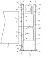
- Main part front view of the overhead traveling vehicle system of the embodiment It is a principal part enlarged plan view of the overhead traveling vehicle system of an Example, and removes and shows the track of an overhead traveling vehicle.
- Block diagram from the ground side terminal to the ground side controller in the embodiment Block diagram of overhead traveling vehicle in the embodiment
- Block diagram of a local cart in the embodiment Diagram showing transfer protocol with load port and buffer
- the overhead traveling vehicle system 2 of the embodiment 4 is an overhead traveling vehicle that travels along the track 6 of the overhead traveling vehicle
- 8 is a local vehicle that travels along the track 10 of the local vehicle.
- the track 10 of the local carriage is provided only around the load ports 16 and 17, and is arranged such that the track 6 of the overhead traveling vehicle 6, the track 10 of the local carriage, and the load ports 16 and 17 are stacked one above the other. 2 and 3, the track 10 of the local carriage is composed of a pair of left and right rails, a rail 10b on the passage 18 side and a rail 10a on the processing device 13 side. Since the gap between the rails 10a and 10b is wider than the left and right widths of the article 14 in FIG. 2, the article 14 and lifting platforms 24 and 26 described later can pass up and down the gap between the rails 10a and 10b.
- the processing device 13 may be provided with one or three or more load ports.
- Numeral 12 is a buffer, which is provided immediately below the track 10 of the local carriage and at a position excluding the upper part of the load ports 16 and 17, and carries an article 14 such as FOUP. Although buffers may be provided at other positions, there is no direct relationship with the embodiment except for the buffer 12 immediately below the track 10.
- Reference numeral 18 denotes a passage for an operator or the like. One of the horizontal planes is the processing apparatus 13 side and the other is the passage 18 side with reference to the load ports 16 and 17. Furthermore, the passage side of the load ports 16 and 17 is a monitoring area of the downward monitoring sensor 36.
- the overhead traveling vehicle 4 includes a lateral movement device 20, a rotation device 21, and a hoist 22.
- the lateral movement device 20 laterally moves the rotation device 21 and the hoist 22 in a direction perpendicular to the track 6 in a horizontal plane. It is made possible to access the buffers (not shown) provided on the left and right sides.
- the turning device 21 turns the hoist 22 to change the direction of the article 14.
- the hoist 22 moves the elevator 24 up and down to transfer the article 14 between the load ports 16 and 17 and the buffer 12.
- the lateral movement device 20 and the rotation device 21 may not be provided.
- Reference numeral 25 denotes a belt that supports the lifting platform 24, and includes, for example, four belts, front, rear, left, and right. Instead of the belt 25, other suspension materials such as a wire and a rope may be used.
- the local carriage 8 includes wheels for traveling on the rails 10 a and 10 b, a traveling motor, and the like, and lifts the lifting platform 26 by the hoist 27 and transfers the article 14 between the buffer 12 and the load ports 16 and 17.
- both the overhead traveling vehicle 4 and the local carriage 8 can transfer the article 14 to the buffer 12 and the load ports 16 and 17.
- the overhead traveling vehicle 4 carries the article 14 into the buffer 12 and the article 14 from the load ports 16 and 17, and the local carriage 8 carries the article from the buffer 12 to the load ports 16 and 17.
- the overhead traveling vehicle system 2 may be operated.
- the tracks 6 and 10 are suspended from, for example, the ceiling side by the columns 28 and 30, and the buffer 12 is suspended from the track 10 by the vertically downward column 32.
- the buffer 12 is provided along the longitudinal direction of the tracks 6 and 10 (the traveling direction of the overhead traveling vehicle 4 and the local carriage 8), for example, both upstream and downstream of the load ports 16 and 17, You may provide only in one of these. Further, there is no member of the buffer 12 such as a horizontal frame directly above the load ports 16 and 17, so that the buffer 12 does not prevent the article 14 from being carried in and out of the load port.
- a downward monitoring sensor 36 is provided immediately above each of the load ports 16 and 17 to monitor obstacles on the passage side of the load ports 16 and 17.
- the obstacle is, for example, an operator whose arm, helmet, or the like is approaching the load ports 16 and 17, and the lower monitoring sensor 36 projects a beam 37, for example, in a fan shape to detect reflected light from the obstacle. It is a sensor.
- the shape of the beam 37 is shown in FIGS. 1 to 3, and the area closer to the passage 18 than the load ports 16 and 17 is monitored except for the lifting path of the article 14 to the load ports 16 and 17 and the load ports 16 and 17. To do.
- the overhead traveling vehicle 4 includes the same downward monitoring sensor 38 for detecting obstacles in the load ports 16 and 17, but there is a high possibility that the track 10 of the local carriage 8 is erroneously detected. Therefore, the signal from the downward monitoring sensor 38 of the overhead traveling vehicle 4 is invalidated for the load ports 16 and 17.
- the downward monitoring sensor 36 is provided for each of the load ports 16 and 17, but the adjacent load ports 16 and 17 may be monitored by one downward monitoring sensor.
- the roll of the article 14 supported by the lifting platforms 24 and 26 is detected. That is, since the article 14 passes through the gap between the rails 10a and 10b, if the article rolls in a direction perpendicular to the longitudinal direction of the track 10 of the local carriage in the horizontal plane, there is a possibility of coming into contact with the rails 10a and 10b. In particular, when the article 14 is raised, if the winding of the four belts 25 is not synchronized, there is a high possibility that the roll will start. Further, when the article 14 is lifted from the load ports 16 and 17, the possibility of rolling is high, and when the article 14 is lifted from the buffer 12, the possibility of rolling is low.
- the roll is detected depending on whether or not the article 14 is in contact with the monitoring line at a position which is the same as or slightly inside the rail 10a in the top and bottom of the track 10 in plan view.
- a light projecting / receiving sensor 40 having a light emitting element and a light receiving element and a mirror 41 are arranged at both ends of the monitoring line.
- the monitoring line L1 is provided at the upper part of the track 10 of the local carriage at least above the load ports 16 and 17, and the monitoring line L2 is preferably provided also at the upper part of the track 10 of the local carriage.
- a monitoring line L3 may be added above the buffer 12 and below the track 10 of the local carriage. *
- FIG. 3 shows the arrangement of the sensors 36 and 40, and the area on the passage side of the load ports 16 and 17 is monitored by the beam 37 by the downward monitoring sensor 36 on the rail 10b side.
- the light emitting / receiving sensor 40 and the mirror 41 monitor the end line on the inner side of the rail 10a and the monitoring line L2 that is the same or slightly inside (on the rail 10b side) in plan view.
- a monitoring line L1 is provided so as to overlap the monitoring line L2, and monitoring is performed by the light projecting / receiving sensor 40 and the mirror 41 attached to the support column 32 and the like.
- a combination of a light emitting element and a light receiving element may be used.
- the light projecting / receiving sensor 40 and the mirror 41 may be provided on the rail 10b side.
- a proximity sensor 43 or the like that monitors the electrostatic capacitance with the ground and detects that the article 14 approaches from the change in electrostatic capacitance may be used instead of the light projecting / receiving sensor 40 and the mirror 41.
- a pole 43 ′ that faces up and down may be attached to the rail 10 a, and the proximity sensor 43 may be attached to the pole 43 ′.
- FIG. 4 shows communication and monitoring during transfer.
- the overhead traveling vehicle 4 includes a communication terminal 56
- the local carriage 8 includes a communication terminal 64.
- Reference numeral 34 denotes a local cart controller that manages the local cart and the loading / unloading of articles to and from the buffer
- reference numeral 48 denotes a processing device side controller that manages the loading / unloading of articles to and from the load port.
- a switch 46 is provided for each pair of buffer and load port, and connects the controllers 34 and 48 to the communication terminals 42 and 44 so that only one of the communication terminals 42 and 44 can communicate with the overhead traveling vehicle 4 or the local cart 8. To do. Further, signals from the lower monitoring sensor 36 and the upper and lower light emitting / receiving sensors 40 are input to the switch 46. When any of these sensors detects an obstacle, the switch 46 detects the communication terminals 42, 44, the overhead traveling vehicle 4, and the local carriage. Communication with 8 is prohibited.
- the overhead traveling vehicle 4 and the local cart 8 transmit a transfer request signal to the terminals 42 and 44 when transferring an article between the buffer or the load port.
- a transfer confirmation signal (a signal indicating that transfer is permitted) is received, the transfer can be started.
- communication is maintained until transfer is completed, and when communication is interrupted during this time, the lifting of the elevator is stopped and communication is resumed.
- the overhead traveling vehicle 4 and the local carriage 8 exchange signals with the terminals 42 and 44.
- the obstacle detection signal may be transmitted to the overhead traveling vehicle 4 or the local carriage 8 by the signals of the downward monitoring sensor 36 and the upper and lower light emitting / receiving sensors 40, but the types of signals increase. , Control becomes complicated.
- FIG. 5 shows a control system of the overhead traveling vehicle 4.
- the communication unit 50 communicates with an overhead traveling vehicle controller (not shown) to receive a conveyance command, and the onboard controller 51 performs overall control on the overhead traveling vehicle 4.
- the map 52 stores the arrangement data of the track 6, and this data includes the transfer position, necessity of monitoring by the lower monitoring sensor 38 at the time of transfer, and the like. For the load ports 16 and 17 provided with the downward monitoring sensor 36, the downward monitoring is unnecessary in the data of the map 52, and the downward monitoring sensor 38 is turned off or its signal is ignored.
- the communication terminal 56 communicates with the ground side terminal 42, exchanges signals in accordance with the transfer protocol, and maintains communication during the transfer.
- the traveling control unit 53 controls traveling of the overhead traveling vehicle 4, and the transfer control unit 54 controls the hoist 22 and the like.
- FIG. 6 shows the control system of the local cart 8, and the communication unit 60 communicates with the local cart controller 34 to receive commands.
- the communication terminal 64 communicates with the ground-side terminal 44, exchanges signals according to the transfer protocol, and maintains communication during the transfer.
- the travel control unit 61 controls the travel of the local carriage 8, and the transfer control unit 62 controls the hoist 27.
- Fig. 7 shows the transfer protocol.
- the overhead traveling vehicle 4 and the local carriage 8 establish communication with the ground side terminals 42 and 44 before the transfer with the buffer 12 and the load ports 16 and 17 (step 1).
- the ground side terminals 42 and 44 are terminals for the same buffer 12 or the same load ports 16 and 17. Since the switch 46 enables communication with only one of the ground side terminals 42 and 44, the overhead traveling vehicle 4 and the local cart 8 simultaneously start transfer to the same buffer 12 or the same load ports 16 and 17. None do.
- the ground side terminal 42 is communicable, the dredged ground side terminal 44 is not communicable, and the state of the switch 46 is set so that the local cart controller 34 can communicate with the ground side terminal 44 in the range where the local cart 8 travels. Switch. From the start of communication to the end of transfer, whether the communication of the ground side terminals 42, 44 can be changed. If it does in this way, the local cart 8 cannot enter below the position where the overhead traveling vehicle 4 starts communication. In addition, the overhead traveling vehicle 4 cannot request communication above the position where the local carriage 8 starts communication.
- the overhead traveling vehicle 4 and the local cart 8 exchange the transfer request signal and the transfer confirmation signal with the ground side terminals 42 and 44 before starting the transfer, and then lower the elevator to move the transfer.
- the downward monitoring sensor 36 attached to the track 10 of the local carriage starts monitoring (step 2), and when an obstacle such as an operator trying to access the load ports 16 and 17 is detected, the switch 46 prohibits communication of the ground side terminals 42 and 44.
- the overhead traveling vehicle 4 and the local carriage 8 stop raising and lowering the elevator and wait for the downward monitoring sensor 36 to detect no obstacle. Further, the downward monitoring sensor 38 of the overhead traveling vehicle 4 is turned off or the overhead traveling vehicle 4 ignores the signal of the downward monitoring sensor 38 according to the map data.
- the light emitting / receiving sensor 40 monitors the roll of the article (steps 3 and 4), and the light emitting / receiving sensor rolls.
- the hoist is stopped and waits for the roll to settle. This monitoring is performed in order to prevent the article from interfering with the track 10 of the local carriage, and monitoring at the lower part of the track 10 may be omitted when the elevator platform is lowered. Note that monitoring of the lower portion of the track 10 may be omitted because the buffer 12 passes the track 10 immediately after the start of ascent.
- the lifting platform is raised. Monitoring by the downward monitoring sensor 36 is continued, and the roll of the article is monitored by the light projecting / receiving sensor 40 when the article passes the lower part and the upper part of the track 10 of the local carriage (steps 3 and 4). . Further, monitoring at the upper part of the track 10 may be omitted when the elevator is raised.
- the monitoring by the downward monitoring sensor is terminated (step 6), and the overhead traveling vehicle 4 and the local vehicle 8 exchange signals with the ground side terminals 42 and 44 that the transfer is completed, Communication is terminated (step 7). Note that the monitoring by the downward monitoring sensor may be terminated when, for example, the article has moved up to the vicinity of the track 10.
- the following effects can be obtained. 1) Since the frame of the buffer 12 is not provided directly above the load ports 16 and 17, the article 14 can be easily transferred. 2) Since the obstacle directly below is detected by the downward monitoring sensor 36 attached to the rail 10b, the obstacle on the passage side of the load ports 16 and 17 can be reliably detected. 3) Since the downward monitoring sensor 38 of the overhead traveling vehicle 4 is not used, the track 10 of the local carriage is not erroneously detected as an obstacle. 4) Since the rolling of the article 14 is detected by the light projecting / receiving sensor 40 before the article 14 passes the track 10 of the local carriage, the article 14 can be prevented from coming into contact with the track 10 of the local carriage.
- the downward monitoring sensor 36 and the light projecting / receiving sensor 40 can be used for both the overhead traveling vehicle 4 and the local cart 8. 6) Regardless of whether the downward monitoring sensor 36 detects an obstacle or the light emitting / receiving sensor 40 detects a roll, the lifting of the lifting platform is stopped by prohibiting the communication of the ground side terminals 42 and 44. it can. 7) By the signal from the downward monitoring sensor 36 or the light projecting / receiving sensor 40, communication is prohibited by the switch 46 without passing through the controllers 34, 48, and therefore the transfer can be stopped more reliably.
Landscapes
- Engineering & Computer Science (AREA)
- Mechanical Engineering (AREA)
- Automation & Control Theory (AREA)
- Warehouses Or Storage Devices (AREA)
- Control And Safety Of Cranes (AREA)
- Container, Conveyance, Adherence, Positioning, Of Wafer (AREA)
- Control Of Position, Course, Altitude, Or Attitude Of Moving Bodies (AREA)
- Electric Propulsion And Braking For Vehicles (AREA)
- Carriers, Traveling Bodies, And Overhead Traveling Cranes (AREA)
Abstract
Description
前記天井走行車の軌道と、
処理装置の前面に設けられているロードポートと、
前記ロードポートの上部で、かつ天井走行車の軌道の直下に設けられているローカル台車の軌道と、
物品を昇降させるホイストを備え、かつ前記ローカル台車の軌道に沿って走行するローカル台車と、
天井走行車及びローカル台車が共に、ホイストにより物品を搬出入できるバッファと、
前記ローカル台車の軌道に取り付けられ、かつ前記ロードポートの付近でかつ処理装置とは反対側の通路側エリアの障害物を監視する第2のセンサと、
第2のセンサの障害物検出信号を前記天井走行車及び前記ローカル台車に送信する通信端末、とが設けられている。
天井走行車及びローカル台車は共に、ホイストによりロードポートに対して物品を搬出入自在で、
前記バッファはローカル台車の軌道から鉛直下向きの支柱により吊り下げられ、かつ前記ロードポートの直上部にはバッファの部材が存在しない。
前記天井走行車及び前記ローカル台車は、第2のセンサからの障害物検出信号を前記通信端末を介して受信すると、ホイストを停止させるように構成され、
前記天井走行車は、前記通路側エリアの障害物を第1のセンサにより監視しないように構成されている。
物品を昇降させるホイストと下方の障害物を監視する第1のセンサとを有する天井走行車と、
前記天井走行車の軌道と、
処理装置の前面に設けられているロードポートと、
前記ロードポートの上部で、かつ天井走行車の軌道の直下に設けられているローカル台車の軌道と、
物品を昇降させるホイストを備え、かつ前記ローカル台車の軌道に沿って走行するローカル台車と、
天井走行車及びローカル台車が共に、ホイストにより物品を搬出入できるバッファ、とから成り、
天井走行車及びローカル台車は共に、ホイストによりロードポートに対して物品を搬出入自在で、
前記バッファはローカル台車の軌道から鉛直下向きの支柱により吊り下げられ、かつ前記ロードポートの直上部にはバッファの部材が存在しない、
天井走行車システムのために、移載を制御する。
この発明の天井走行車システムのための移載制御方法では、前記ロードポートの付近でかつ処理装置とは反対側の通路側エリアの障害物を監視する第2のセンサを、前記ローカル台車の軌道に取り付けるステップと、
第2のセンサの障害物検出信号を前記天井走行車及び前記ローカル台車に送信する通信端末を設けるステップと、
前記天井走行車及び前記ローカル台車に、第2のセンサからの障害物検出信号を前記通信端末を介して受信した際に、ホイストを停止させるステップと、
前記天井走行車に、前記通路側エリアの障害物を第1のセンサにより監視しないようにさせるステップ、とを実行する。
前記通信端末は、前記天井走行車の軌道及びローカル台車の軌道に各々設けられ、かつ前記ロードポートへの物品の搬出入を管理する処理装置側のコントローラと接続され、
天井走行車及びローカル台車は、前記通信端末と通信しながら、ロードポートへの物品の搬出入を行い、
前記通信端末との通信が遮断されることが、前記天井走行車及び前記ローカル台車に対し、前記障害物検出信号として作用する。
1) ロードポート16,17の直上部にバッファ12のフレーム等がないので、物品14の移載が容易である。
2) レール10bに取り付けた下方監視センサ36により直下の障害物を検出するので、ロードポート16,17の通路側の障害物を確実に検出できる。
3) 天井走行車4の下方監視センサ38を用いないので、ローカル台車の軌道10等を障害物として誤検出することがない。
4) 物品14がローカル台車の軌道10を通過する前に、投受光センサ40により物品14の横揺れを検出するので、物品14がローカル台車の軌道10に接触することを防止できる。
5) 下方監視センサ36及び投受光センサ40を、天井走行車4とローカル台車8の双方のために用いることができる。
6) 下方監視センサ36が障害物を検出しても、投受光センサ40が横揺れを検出しても、いずれも地上側端末42,44の通信を禁止することにより、昇降台の昇降を停止できる。
7) 下方監視センサ36または投受光センサ40の信号により、コントローラ34,48を経由せずに、スイッチ46により通信を禁止する、従ってより確実に移載を停止させることができる。
8 ローカル台車 10 ローカル台車の軌道 12 バッファ
13 処理装置 14 物品 16,17 ロードポート
18 通路 20 横移動装置 21 回動装置
22,27 ホイスト 24,26 昇降台 25 ベルト
28~32 支柱 34 ローカル台車コントローラ
36,38 下方監視センサ 37 レーザビーム
40 投受光センサ 41 ミラー 42,44 地上側端末
43 近接センサ 46 スイッチ 48 処理装置側コントローラ
50,60 通信部 51 機上コントローラ 52 マップ
53,61 走行制御部 54,62 移載制御部
56,64 通信端末
L1~L3 監視ライン
Claims (4)
- 物品を昇降させるホイストと下方の障害物を監視する第1のセンサとを有する天井走行車と、
前記天井走行車の軌道と、
処理装置の前面に設けられているロードポートと、
前記ロードポートの上部で、かつ天井走行車の軌道の直下に設けられているローカル台車の軌道と、
物品を昇降させるホイストを備え、かつ前記ローカル台車の軌道に沿って走行するローカル台車と、
天井走行車及びローカル台車が共に、ホイストにより物品を搬出入できるバッファと、
前記ローカル台車の軌道に取り付けられ、かつ前記ロードポートの付近でかつ処理装置とは反対側の通路側エリアの障害物を監視する第2のセンサと、
第2のセンサの障害物検出信号を前記天井走行車及び前記ローカル台車に送信する通信端末、とから成り、
天井走行車及びローカル台車は共に、ホイストによりロードポートに対して物品を搬出入自在で、
前記バッファはローカル台車の軌道から鉛直下向きの支柱により吊り下げられ、かつ前記ロードポートの直上部にはバッファの部材が存在せず、
前記天井走行車及び前記ローカル台車は、第2のセンサからの障害物検出信号を前記通信端末を介して受信すると、ホイストを停止させるように構成され、
かつ前記天井走行車は、前記通路側エリアの障害物を第1のセンサにより監視しないように構成されている、天井走行車システム。 - 前記ローカル台車の軌道は処理装置側と通路側との一対の平行なレールから成り、前記一対のレールの間に前記物品が鉛直方向に通過自在な隙間が設けられ、
前記第2のセンサは通路側のレールに設けられていることを特徴とする、請求項1の天井走行車システム。 - 前記第2のセンサに接続され、かつ前記第2のセンサが障害物を検出していないことを条件に、天井走行車あるいはローカル台車と、前記通信端末との通信を成立させるスイッチが、さらに設けられ、
前記通信端末は、前記天井走行車の軌道及びローカル台車の軌道に各々設けられ、かつ前記ロードポートへの物品の搬出入を管理する処理装置側のコントローラと接続され、
天井走行車及びローカル台車は、前記通信端末と通信しながら、ロードポートへの物品の搬出入を行い、
前記通信端末との通信が遮断されることが、前記天井走行車及び前記ローカル台車に対し、前記障害物検出信号として作用するように構成されている、ことを特徴とする、請求項1または2の天井走行車システム。 - 物品を昇降させるホイストと下方の障害物を監視する第1のセンサとを有する天井走行車と、
前記天井走行車の軌道と、
処理装置の前面に設けられているロードポートと、
前記ロードポートの上部で、かつ天井走行車の軌道の直下に設けられているローカル台車の軌道と、
物品を昇降させるホイストを備え、かつ前記ローカル台車の軌道に沿って走行するローカル台車と、
天井走行車及びローカル台車が共に、ホイストにより物品を搬出入できるバッファ、とから成り、
天井走行車及びローカル台車は共に、ホイストによりロードポートに対して物品を搬出入自在で、
前記バッファはローカル台車の軌道から鉛直下向きの支柱により吊り下げられ、かつ前記ロードポートの直上部にはバッファの部材が存在しない、
天井走行車システムのための移載制御方法であって、
前記ロードポートの付近でかつ処理装置とは反対側の通路側エリアの障害物を監視する第2のセンサを、前記ローカル台車の軌道に取り付けるステップと、
第2のセンサの障害物検出信号を前記天井走行車及び前記ローカル台車に送信する通信端末を設けるステップと、
前記天井走行車及び前記ローカル台車に、第2のセンサからの障害物検出信号を前記通信端末を介して受信した際に、ホイストを停止させるステップと、
前記天井走行車に、前記通路側エリアの障害物を第1のセンサにより監視しないようにさせるステップ、とを実行する、天井走行車システムのための移載制御方法。
Priority Applications (6)
| Application Number | Priority Date | Filing Date | Title |
|---|---|---|---|
| US14/412,225 US10037908B2 (en) | 2012-07-26 | 2013-06-18 | Overhead traveling vehicle system and transfer control method for overhead traveling vehicle system |
| JP2014526819A JP5936174B2 (ja) | 2012-07-26 | 2013-06-18 | 天井走行車システム及び天井走行車システムでの移載制御方法 |
| EP13822626.1A EP2878552B1 (en) | 2012-07-26 | 2013-06-18 | Overhead traveling vehicle system and transfer control method for overhead traveling vehicle system |
| CN201380034416.9A CN104395207B (zh) | 2012-07-26 | 2013-06-18 | 桥式行驶车系统以及桥式行驶车系统中的移载控制方法 |
| SG11201407694VA SG11201407694VA (en) | 2012-07-26 | 2013-06-18 | Overhead traveling vehicle system and transfer control method for overhead traveling vehicle system |
| KR1020147034264A KR101680271B1 (ko) | 2012-07-26 | 2013-06-18 | 천정 주행차 시스템 및 천정 주행차 시스템에서의 이재 제어 방법 |
Applications Claiming Priority (2)
| Application Number | Priority Date | Filing Date | Title |
|---|---|---|---|
| JP2012-165564 | 2012-07-26 | ||
| JP2012165564 | 2012-07-26 |
Publications (1)
| Publication Number | Publication Date |
|---|---|
| WO2014017221A1 true WO2014017221A1 (ja) | 2014-01-30 |
Family
ID=49997037
Family Applications (1)
| Application Number | Title | Priority Date | Filing Date |
|---|---|---|---|
| PCT/JP2013/066700 Ceased WO2014017221A1 (ja) | 2012-07-26 | 2013-06-18 | 天井走行車システム及び天井走行車システムでの移載制御方法 |
Country Status (8)
| Country | Link |
|---|---|
| US (1) | US10037908B2 (ja) |
| EP (1) | EP2878552B1 (ja) |
| JP (1) | JP5936174B2 (ja) |
| KR (1) | KR101680271B1 (ja) |
| CN (1) | CN104395207B (ja) |
| SG (1) | SG11201407694VA (ja) |
| TW (1) | TWI534056B (ja) |
| WO (1) | WO2014017221A1 (ja) |
Cited By (4)
| Publication number | Priority date | Publication date | Assignee | Title |
|---|---|---|---|---|
| WO2015194266A1 (ja) * | 2014-06-19 | 2015-12-23 | 村田機械株式会社 | キャリアの一時保管装置と保管方法 |
| WO2020090254A1 (ja) * | 2018-10-29 | 2020-05-07 | 村田機械株式会社 | 天井走行車、天井走行車システム、及び障害物の検出方法 |
| US11027949B2 (en) * | 2016-05-20 | 2021-06-08 | Murata Machinery, Ltd. | Transport vehicle and transport method |
| KR20240016202A (ko) | 2022-07-28 | 2024-02-06 | 가부시키가이샤 다이후쿠 | 물품 반송 설비 |
Families Citing this family (18)
| Publication number | Priority date | Publication date | Assignee | Title |
|---|---|---|---|---|
| PT2620391E (pt) * | 2012-01-30 | 2014-08-26 | Carefusion Germany 326 Gmbh | Método para retirar de armazenamento embalagens de medicamentos |
| TWI520258B (zh) * | 2013-09-27 | 2016-02-01 | 華亞科技股份有限公司 | 起吊裝置及自動化搬運系統 |
| JP6252676B2 (ja) * | 2014-06-19 | 2017-12-27 | 村田機械株式会社 | キャリアの一時保管装置及び一時保管方法 |
| SG11201700646RA (en) * | 2014-09-10 | 2017-03-30 | Murata Machinery Ltd | Temporary storage system, conveyance system using same, and temporary storage method |
| EP3389084B1 (en) * | 2015-12-08 | 2022-03-16 | Murata Machinery, Ltd. | Conveyance system and conveyance method |
| WO2017098804A1 (ja) * | 2015-12-08 | 2017-06-15 | 村田機械株式会社 | 搬送システム |
| CN108698759A (zh) * | 2016-03-03 | 2018-10-23 | 村田机械株式会社 | 临时保管系统 |
| KR102020227B1 (ko) * | 2017-08-24 | 2019-09-10 | 세메스 주식회사 | 캐리어 이송 장치 및 방법 |
| US10622236B2 (en) * | 2017-08-30 | 2020-04-14 | Taiwan Semiconductor Manufacturing Co., Ltd. | Apparatus and method for handling wafer carrier doors |
| GB201803771D0 (en) * | 2018-03-09 | 2018-04-25 | Ocado Innovation Ltd | Transporting device position determining apparatus and method |
| KR102080877B1 (ko) * | 2018-05-28 | 2020-02-24 | 세메스 주식회사 | 레이스웨이 유닛 및 이를 갖는 oht |
| CN113371614B (zh) * | 2020-03-10 | 2023-01-31 | 长鑫存储技术有限公司 | 自动化天车防撞系统及方法 |
| JP7456518B2 (ja) * | 2020-11-17 | 2024-03-27 | 村田機械株式会社 | 天井搬送車 |
| KR102635821B1 (ko) | 2021-02-15 | 2024-02-08 | 삼성전자주식회사 | 기판 이송 장치 및 기판 이송 방법 |
| CN115028103B (zh) * | 2022-06-09 | 2024-01-09 | 长鑫存储技术有限公司 | 一种装载装置及自动物料搬送系统 |
| JP7786322B2 (ja) * | 2022-09-08 | 2025-12-16 | 株式会社ダイフク | 搬送装置および搬送方法 |
| JPWO2024070303A1 (ja) * | 2022-09-29 | 2024-04-04 | ||
| US20250321573A1 (en) * | 2024-04-16 | 2025-10-16 | Nanya Technology Corporation | Automatic handling system and method of operating the same |
Citations (4)
| Publication number | Priority date | Publication date | Assignee | Title |
|---|---|---|---|---|
| JP2005294614A (ja) * | 2004-04-01 | 2005-10-20 | Asyst Shinko Inc | 警報および通報装置 |
| JP2006298567A (ja) * | 2005-04-20 | 2006-11-02 | Murata Mach Ltd | 天井走行車 |
| JP2009029529A (ja) * | 2007-07-24 | 2009-02-12 | Hokuyo Automatic Co | 搬送台車及び光測距装置 |
| JP2012111635A (ja) | 2010-11-04 | 2012-06-14 | Muratec Automation Co Ltd | 搬送システム及び搬送方法 |
Family Cites Families (9)
| Publication number | Priority date | Publication date | Assignee | Title |
|---|---|---|---|---|
| JP4465415B2 (ja) | 2000-03-15 | 2010-05-19 | ムラテックオートメーション株式会社 | 天井走行搬送装置 |
| JP2007331906A (ja) * | 2006-06-16 | 2007-12-27 | Murata Mach Ltd | 天井走行車システム |
| JP4688824B2 (ja) * | 2007-01-12 | 2011-05-25 | 村田機械株式会社 | 天井走行車システム及び天井走行車システムの周囲の処理装置の搬出入方法 |
| KR101015225B1 (ko) * | 2008-07-07 | 2011-02-18 | 세메스 주식회사 | 기판 처리장치 및 이의 기판 이송 방법 |
| JP4807424B2 (ja) * | 2009-03-17 | 2011-11-02 | 村田機械株式会社 | 天井搬送システムと物品の移載方法 |
| JP5445015B2 (ja) * | 2009-10-14 | 2014-03-19 | シンフォニアテクノロジー株式会社 | キャリア移載促進装置 |
| JP2011114406A (ja) * | 2009-11-24 | 2011-06-09 | Sony Corp | 撮像装置、撮像方法およびプログラム |
| JP5429570B2 (ja) * | 2010-03-08 | 2014-02-26 | 株式会社ダイフク | 物品搬送設備 |
| JP5382470B2 (ja) * | 2010-11-04 | 2014-01-08 | 村田機械株式会社 | 搬送システム及び搬送方法 |
-
2013
- 2013-06-18 EP EP13822626.1A patent/EP2878552B1/en active Active
- 2013-06-18 KR KR1020147034264A patent/KR101680271B1/ko active Active
- 2013-06-18 WO PCT/JP2013/066700 patent/WO2014017221A1/ja not_active Ceased
- 2013-06-18 SG SG11201407694VA patent/SG11201407694VA/en unknown
- 2013-06-18 CN CN201380034416.9A patent/CN104395207B/zh active Active
- 2013-06-18 JP JP2014526819A patent/JP5936174B2/ja active Active
- 2013-06-18 US US14/412,225 patent/US10037908B2/en active Active
- 2013-07-24 TW TW102126433A patent/TWI534056B/zh active
Patent Citations (4)
| Publication number | Priority date | Publication date | Assignee | Title |
|---|---|---|---|---|
| JP2005294614A (ja) * | 2004-04-01 | 2005-10-20 | Asyst Shinko Inc | 警報および通報装置 |
| JP2006298567A (ja) * | 2005-04-20 | 2006-11-02 | Murata Mach Ltd | 天井走行車 |
| JP2009029529A (ja) * | 2007-07-24 | 2009-02-12 | Hokuyo Automatic Co | 搬送台車及び光測距装置 |
| JP2012111635A (ja) | 2010-11-04 | 2012-06-14 | Muratec Automation Co Ltd | 搬送システム及び搬送方法 |
Non-Patent Citations (1)
| Title |
|---|
| See also references of EP2878552A4 |
Cited By (10)
| Publication number | Priority date | Publication date | Assignee | Title |
|---|---|---|---|---|
| WO2015194266A1 (ja) * | 2014-06-19 | 2015-12-23 | 村田機械株式会社 | キャリアの一時保管装置と保管方法 |
| JPWO2015194266A1 (ja) * | 2014-06-19 | 2017-04-20 | 村田機械株式会社 | キャリアの一時保管装置と保管方法 |
| US10186442B2 (en) * | 2014-06-19 | 2019-01-22 | Murata Machinery, Ltd | Carrier buffering device and storage method |
| US11027949B2 (en) * | 2016-05-20 | 2021-06-08 | Murata Machinery, Ltd. | Transport vehicle and transport method |
| WO2020090254A1 (ja) * | 2018-10-29 | 2020-05-07 | 村田機械株式会社 | 天井走行車、天井走行車システム、及び障害物の検出方法 |
| JPWO2020090254A1 (ja) * | 2018-10-29 | 2021-09-30 | 村田機械株式会社 | 天井走行車、天井走行車システム、及び障害物の検出方法 |
| JP7040637B2 (ja) | 2018-10-29 | 2022-03-23 | 村田機械株式会社 | 天井走行車、天井走行車システム、及び障害物の検出方法 |
| TWI825204B (zh) * | 2018-10-29 | 2023-12-11 | 日商村田機械股份有限公司 | 高架行走車、高架行走車系統及障礙物的檢出方法 |
| KR20240016202A (ko) | 2022-07-28 | 2024-02-06 | 가부시키가이샤 다이후쿠 | 물품 반송 설비 |
| US12630369B2 (en) | 2022-07-28 | 2026-05-19 | Daifuku Co., Ltd. | Object transport system |
Also Published As
| Publication number | Publication date |
|---|---|
| EP2878552A1 (en) | 2015-06-03 |
| CN104395207A (zh) | 2015-03-04 |
| US20150170946A1 (en) | 2015-06-18 |
| TW201412618A (zh) | 2014-04-01 |
| JPWO2014017221A1 (ja) | 2016-07-07 |
| JP5936174B2 (ja) | 2016-06-15 |
| KR101680271B1 (ko) | 2016-11-28 |
| TWI534056B (zh) | 2016-05-21 |
| US10037908B2 (en) | 2018-07-31 |
| SG11201407694VA (en) | 2014-12-30 |
| CN104395207B (zh) | 2016-07-06 |
| EP2878552A4 (en) | 2016-03-09 |
| EP2878552B1 (en) | 2021-01-13 |
| KR20150016315A (ko) | 2015-02-11 |
Similar Documents
| Publication | Publication Date | Title |
|---|---|---|
| JP5936174B2 (ja) | 天井走行車システム及び天井走行車システムでの移載制御方法 | |
| JPWO2014017222A1 (ja) | 天井走行車システム及び天井走行車システムの制御方法 | |
| JP6520797B2 (ja) | 物品搬送設備 | |
| JP6652106B2 (ja) | 物品搬送設備 | |
| JP6632838B2 (ja) | 車両搬送方法 | |
| JP5928926B2 (ja) | 搬送システム及び搬送車システムでの排他制御方法 | |
| CN107922116A (zh) | 输送系统 | |
| WO2012108098A1 (ja) | 有軌道台車システム | |
| JP2012111635A (ja) | 搬送システム及び搬送方法 | |
| CN105984701A (zh) | 搬运台车和搬运台车系统 | |
| CN110615361A (zh) | 一种轮胎式龙门起重机的远程操作系统及起重机 | |
| CN106463443B (zh) | 载体的临时保管装置以及保管方法 | |
| JPH11180505A (ja) | 有軌道台車システム | |
| JP5103714B2 (ja) | 搬送設備 | |
| JP2003267518A (ja) | 物流設備 | |
| JP2001163408A (ja) | スタッカークレーン | |
| JP7589704B2 (ja) | スタッカークレーン | |
| JP2005284780A (ja) | 有軌道台車システム | |
| KR20080025463A (ko) | 반도체 제조 장치의 자동 반송 장치 | |
| JP2013205954A (ja) | 無人搬送車システム |
Legal Events
| Date | Code | Title | Description |
|---|---|---|---|
| 121 | Ep: the epo has been informed by wipo that ep was designated in this application |
Ref document number: 13822626 Country of ref document: EP Kind code of ref document: A1 |
|
| ENP | Entry into the national phase |
Ref document number: 20147034264 Country of ref document: KR Kind code of ref document: A |
|
| ENP | Entry into the national phase |
Ref document number: 2014526819 Country of ref document: JP Kind code of ref document: A |
|
| WWE | Wipo information: entry into national phase |
Ref document number: 2013822626 Country of ref document: EP |
|
| WWE | Wipo information: entry into national phase |
Ref document number: 14412225 Country of ref document: US |
|
| NENP | Non-entry into the national phase |
Ref country code: DE |